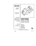
1
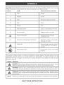
i
T
Double Insulated
Model Nos.
315.175101
315.175111
7/16
Save this manual
future reference
A
CAUTION:
for
. Safety
. Features
Read and
follow all Safety Rules and
Operating Instructions before
first use of this product.
Customer
• Operation
• Maintenance
• Parts List
Help Line: 1-800-932-3188
Sears, Roebuck and Co., 3333 Beverly Rd., Hoffman
Visit the Craftsman Web page: www.sears.com/craftsman
Estates,
IL 60179
USA
C
983000-430
6-04
[]
Warranty .............................................................................................................................................................
2
[]
Introduction .........................................................................................................................................................
2
[]
General Safety Rules .....................................................................................................................................
[]
Specific Safety Rules .........................................................................................................................................
4
[]
Symbols ..............................................................................................................................................................
5
[]
Specifications
6
[]
Unpacking ...........................................................................................................................................................
[]
Features .........................................................................................................................................................
[]
Adjustments ..................................................................................................................................................
[]
Operation ....................................................................................................................................................
[]
Maintenance .....................................................................................................................................................
18
[]
Accessories ......................................................................................................................................................
19
[]
Exploded View and Repair Parts List .........................................................................................................
[]
Parts, Ordering, and Service ............................................................................................................................
3-4
.....................................................................................................................................................
FULL ONE YEAR WARRANTY
ONCRAFTSMRN
6
7-8
9-11
12-17
20-21
22
ROUTER
If this t'RAF'[$MRN Router fails to give complete satisfaction within one year from the date of purchase,
RETURN iT TO THE NEAREST SEARS STORE tN THE UNITED STATES, and Sears will repair it, free of
charge.
If this CR,R}:T_MRN Router is used for commercial
from the date of purchase.
or rental purposes, this warranty applies for only 90 days
This warranty gives you specific legal rights, and you may also have other rights which vary from state to state.
Sears, Roebuck and Co., Dept. 817 WA, Hoffman
Estates, tL 60179
Your router has many features for making routing
operations more pleasant and enjoyable. Safety,
performance and dependability have been given top
priority in the design of this router making it easy to
maintain and operate.
,_
Look for this symbol to point
Your safety is involved.
_
out important
safety
CAUTION:
Carefully read through this entire
operator's manual before using your new router.
Pay close attention to the Rules for Safe
Operation, Warnings and Cautions. If you use
your router properly and only for what it is
intended, you will enjoy years of safe, reliable
service.
precautions.
It means
attention!!!
WARNING:
The operation of any router can result in foreign objects being thrown into your
eyes, which can result in severe eye damage. Before beginning power tool operation,
always wear safety goggles or safety glasses with side shields and a full face shield when
needed. We recommend Wide Vision Safety Mask for use over eyeglasses or standard
safety glasses with side shields, available at Sears Retail Stores. Always wear eye
protection which is marked to comply with ANSI Z87.1.
2
WARNING:Readandunderstand
all
instructions,
Failuretofollowallinstructions
listedbelow,mayresultinelectricshock,fire
and/orseriouspersonalinjury,
SAVE THESE
WORK
mNSTRUCTIONS
AREA
[] Keep your work area dean and welt lit. Cluttered
benches and dark areas invite accidents.
[] Do not operate power tooJs in explosive atmospheres, such as in the presence of flammable
liquids, gases, or dust. Power tools may create
sparks which may ignite the dust or fumes.
[] Keep bystanders, children, and visitors away
while operating a power tool. Distractions can
cause you to lose control.
ELECTRICAL
SAFETY
[] Double insuJated tools are equipped with a
poJadzed plug (one blade is wider than the
other). This pJug will fit in a polarized outJet only
one way. if the pJug does not fit fully in the
outlet, reverse the ptug. _f it still does not fit,
contact a qualified electrician to install a polarized outlet. Do not change the pJug in any way.
clothing, and gloves away from moving parts.
Loose clothes, jewelry, or long hair can be caught in
moving parts.
[] Avoid
before
on the
switch
accidentaJ starting. Be sure switch is off
plugging in. Carrying tools with your finger
switch or plugging in tools that have the
on, invites accidents.
[] Remove adjusting keys or wrenches before
turning the tool on. A wrench or a key that is left
attached to a rotating part of the tool may result in
personal injury.
[] Do not overreach. Keep proper footing and
balance at aH times. Proper footing and balance
enables better control of the tool in unexpected
situations. Do not use on a ladder or unstable
support.
[] Use safety equipment. Always wear eye protection. Dust mask, non-skid safety shoes, hard hat,
or hearing protection must be used for appropriate
conditions.
TOOL
USE AND
CARE
[] Use cJamps or other practical way to secure
and support the workpiece to a stable platform.
Holding the work by hand or against your body is
unstable and may lead to loss of control.
Double insulation _'_ eliminates the need for the
three-wire grounded power cord and grounded
power supply system.
[] Do not force tool Use the correct tool for your
application. The correct tool will do the job better
and safer at the rate for which it is designed.
[] Avoid body contact with grounded surfaces, such
as pipes, radiators, ranges, and refrigerators.
There is an increased risk of electric shock if your
body is grounded.
[] Do not use tool if switch does not turn it on or
off. Any tool that cannot be controlled with the
switch is dangerous and must be repaired.
[] Don't expose power tools to rain or wet conditions. Water entering a power tool will increase the
risk of electric shock.
[] Do not abuse the cord. Never use the cord to carry
the tooJs or pull the pJug from an outlet. Keep cord
away from heat, oil, sharp edges, or moving parts.
RepJace damaged cords immediately. Damaged
cords increase the risk of electric shock.
[] When operating a power tool outside, use an outdoor extension cord marked "W-A" or "W'. These
cords are rated for outdoor use and reduce the risk of
electric shock.
PERSONAL
SAFETY
[] Stay aJert, watch what you are doing and use
common sense when operating a power tool
Do not use tooJ while tired or under the influence of drugs, alcohol, or medication. A moment
of inattention while operating power tools may
result in serious personal injury.
[] Dress property. Do not wear loose clothing
jewelry. Contain tong hair. Keep your hair,
or
[] Disconnect the plug from power source before
making any adjustments,
changing accessories, or storing the tool Such preventive safety
measures reduce the risk of starting the tool
accidentally.
[] Store idJe tools out of the reach of children and
other untrained persons. Tools are dangerous in
the hands of untrained users.
[] Maintain tools with care. Keep cutting tools
sharp and dean. Properly maintained tools with
sharp cutting edges are less likely to bind and are
easier to control.
[] Check for misaJignment or binding of moving
parts, breakage of parts, and any other condition that may affect the tooJ's operation, ff
damaged, have the tool serviced before using.
Many accidents are caused by poorly maintained
tools.
[] Use only accessories that are recommended by
the manufacturer for your model Accessories
that may be suitable for one tool, may become
hazardous when used on another tool.
SERVICE
[] TooJservicemustbeperformedonly
by qualified repair personnel Service or maintenance
performed by unqualified personnel could result in
a risk of injury.
[] When servicing a tool, use onJy identical replacement parts. Follow instructions in the
Maintenance section of this manual Use of
unauthorized parts or faiJure to foJlow Maintenance
Instructions may create a risk of electric shock or
injury.
Hold tool by insuJated gripping surfaces when performing an operation where the cutting tool may
contact bidden wiring or its cord. Contact with a "live" wire wiJJmake exposed metaJ parts of the tool "live" and
shock the operator.
ADDmTIONAL
RULES
FOR SAFE
OPERATION
[] Know your power tool Read operator's manuaJ
carefulJy. Learn its appJications and Jimitations,
as well as the specific potential hazards related
to this tool FoJJowing this rule wiJJreduce the risk
of eJectdc shock, fire, or serious injury.
[] AJways wear safety glasses. Everyday eyeglasses have only impact=resistant
lenses; they
are NOT safety glasses. FoJJowing this ruJe wiJJ
reduce the risk of serious personal injury.
[] Make sure your extension cord is in good
condition. When using an extension cord, be
sure to use one heavy enough to carry the
current your product will draw. A wire gage size
(A.W.G.) of at least 16 is recommended for an
extension cord 100 feet or tess in Jength. A cord
exceeding 100 feet is not recommended,
ff in
doubt, use the next heavier gage. The smaller
the gage number, the heavier the cord. An
undersized cord wilJ cause a drop in Jine voJtage
resulting in loss of power and overheating.
[] Protect your lungs. Wear a face or dust mask if
the operation is dusty. FoJJowing this rule wiJl
reduce the risk of serious personal injury.
[] Inspect for and remove aH naris from lumber
before routing. FoJJowing this ruJe wiJl reduce the
risk of serious personal injury.
[] Protect your hearing. Wear hearing protection
during extended periods of operation. FoJJowing
this rule wiJJreduce the risk of serious personaJ
injury.
[] Drugs, aicohoJ, medication. Do not operate tooJ
while under the influence of drugs, aJcohoL or
any medication. FoJJowing this rule wiJJreduce the
risk of electric shock, fire, or serious personaJ injury.
[] Inspect tool cords periodically and, if damaged,
have repaired at your nearest authorized service center. ConstantJy stay aware of cord
location. FoJJowing this ruJe wiJJreduce the risk of
eJectric shock or fire.
[] Save these instructions.
Refer to them frequentJy and use them to instruct others who
may use this tool ff you Joan someone this tool,
loan them these instructions also.
[] Check damaged parts. Before further use of the
tool a guard or other part that is damaged
shouJd be carefully checked to determine that it
will operate propedy and perform its intended
function. Check for aJignment of moving parts,
binding of moving parts, breakage of parts,
mounting, and any other conditions that may
affect its operation. A guard or other part that is
damaged should be property repaired or replaced by an authorized service center. FoJJow°
ing this rule wiJJreduce the risk of shock, fire, or
serious injury.
WARNING:
Some dust created by power
sanding, sawing, grinding, driJJing, and other
construction activities contains chemicals known
to cause cancer, birth defects or other
reproductive harm. Some exampJes of these
chemicals are:
[] Do not abuse cord. Never carry the tooJ by the
cord or yank it to disconnect it from the receptacle. Keep cord away from heat, oil, and sharp
edges. FoJJowing this ruJe wiJJreduce the risk of
electric shock or fire.
Your risk from these exposures varies,
depending on how often you do this type of work.
To reduce your exposure to these chemicals:
work in a weJJventiJated area, and work with
approved safety equipment, such as those dust
masks that are specially designed to fiJter out
microscopic particJes.
, lead from lead=based paints,
• crystaJiine silica from bricks and cement and
other masonry products, and
• arsenic and chromium
treated Jumber.
from chemicaJly=
Important:Someofthefollowingsymbolsmaybeusedonyourtool.Pleasestudythemandlearntheirmeaning.
Properinterpretation
ofthesesymbolswillallowyoutooperatethetoolbetterandsafer.
SYMBOL
NAME
DESIGNATION/EXPLANATION
V
Volts
Voltage
A
Amperes
Current
Hz
Hertz
Frequency
(cyclespersecond)
W
Watt
Power
min
Minutes
Time
%
AlternatingCurrent
Typeor a characteristic
ofcurrent
no
NoLoadSpeed
Rotational
speed,atnoload
ClassII Construction
Designates
double-insulated
construction
tools
Revolutions
or Reciprocation
PerMinute
Revolutions,
strokes,surfacespeed,
orbitsetc.perminute
SafetyAlert
Indicates
danger,warningorcaution.
It meansattention!!!
Yoursafetyis
involved.
WetConditions
Alert
Donotexposetorainor usein damp
locations.
.../min
Thepurposeof safetysymbolsis to attractyourattentionto possibledangers.Thesafetysymbols,andthe
explanations
withthem,deserveyour carefulattentionandunderstanding.
The safetywarningsdo not by
themselves
eliminateanydanger.Theinstructions
or warningstheygivearenotsubstitutes
forproperaccident
prevention
measures.
SYMBOL blEANING
DANGER:Failure
toobeyasafety
warning
willresultinserious
injurytoyourselfortoothers.
follow
thesafetyprecautions
toreduce
theriskoffire,electric
shockandpersonal
injury. Always
A
WARNING:Failure
to obeya safetywarning
in serious
yourself
or toinjury.
others.
Alwaysfollowthesafetyprecautions
to reducecanresult
theriskoffire,
electric injury
shocktoand
personal
A
yourself
AUTION:
or to others.
Failure Always
to obey follow
a safety
the warning
safety precautions
may result toinreduce
property
thedamage
risk of fire,
or electric
personalshock
injuryand
to
personal injury.
NOTE:
Advises you of information or instructions vital to the operation or maintenance of the equipment.
SAVE THESE INSTRUCTIONS
Depth of Cut
CoHet
0 =1=1/2 in.
1/4 in.
Horsepower
Model No. 315.175101
Model No. 315.175111
1-1/2
1-3/4
Ampere
Model No. 315.175101
Model No. 315.175111
8.5 Amps
9.0 Amps
Your router has been shipped completely assembled.
Inspect it carefuJJy to mare sure no breakage or
damage has occurred during shipping. If any parts are
damaged or missing, contact your nearest Sears
Retail Store to obtain replacement parts before
attempting to operate router. A wrench and this
operator's manuaJ are aJso incJuded.
Input
120 Volts, 60 Hz, AC only
No Load Speed
Model No. 315.175101
Model No. 315.175111
Power Cord
Net Weight
Model No. 315.175101
Model No. 315.175111
_
25,000/min
15,000 - 25,000imin
10 ft.
7 ibs. 3 oz.
7 Ibs. 9.5 oz.
WARNING:
If any parts are missing, do not
operate this tool until the missing parts are
repJaced. FaiJure to do so couJd result in possibJe
serious personaJ injury.
DOUBLEmNSULATmON
Doubleinsulationis a conceptin safetyinelectric
powertools,whicheliminates
theneedfortheusual
three-wire
groundedpowercord.All exposed metal
parts are isolated from the internal metal motor
components with protecting insulation, Double
insulated tools do not need to be grounded,
Important: Servicing of a tool with double insulation
requires extreme care and knowledge of the system
and should be performed only by a qualified service
technician, For service, we suggest you return the tool
to your nearest authorized service center for repair,
Always use original factory replacement parts when
servicing,
,_i
WARNING:
The double insulated system is
intended to protect the user from shock resulting
from a break in the tool's internal wiring. Observe
all normal safety precautions to avoid electrical
shock,
ELECTRIC
MOTOR
DEPTH
ADJUSTmNG
RING
The depth adjusting ring allows you to adjust the
depth of cut.
LOCKING
ARM
The locking arm secures the motor housing in the
base.
CHIP SHmELD
A clear plastic chip shield is installed on the front of
your router for protection against flying dust and
chips The shield is designed to fit the opening of the
router base. If necessary to remove chip shield,
squeeze the tabs on each end and pull outward. To
replace, squeeze the tabs at each end, fit into
opening, then release, For your protection, do not
use router without chip shield properly in place.
Peel the horsepower label from chip shield and
discard,
VARIABLE
SPEED
(MODEL NO. 315.175111
See Figure 1.
ONLY)
Your router has a precision built electric motor, It
should be connected to a power supply that is 120
voJts, 60 Hz, AC only (normal household current),
Do not operate this tool on direct current (DC), A
substantial voltage drop will cause a loss of power
and the motor wiii overheat, if your tool does not
operate when plugged into an outlet, double-check
the power supply,
Your router has advanced electronic features,
designed to assist you in getting the maximum use
from your router, By making proper speed selections,
your router can be adjusted to specific routing needs,
This eliminates much of the guess work previously
needed to perform a given job. Both the experienced
and inexperienced router users benefit, obtaining
professional like results with fewer job errors,
SWITCH
The variable speed control allows the router speed to
be adjusted from 15,000 to 25,000 RPM. The
variable speed control selector is conveniently located
on the top of the motor housing,
To turn the router ON, toggle the switch to the I
position. To turn the router OFF, toggle the switch to
the O position.
SPmNDLE LOCK
The spindle lock secures the spindle while you make
adjustments and acts as a retainer to keep the router
body from coming out of the base,
Speed can be set according to the approximate cutter
diameter you will be using and to the hardness of the
material being cut. The best cuts are made when the
cutter is fed through material at the proper rate of
feed,
VARIABLE
SPEED
DiAL
(MODEL
315.175111)
HANDLE
oPOWER
HANDLE
CHIP
SHIELD
WRENCH
DEPTH
ADJUSTING
RING
DEPTH
INDICATOR
RING
LOCKIN(
SPINDLE
LOCK
COLLET
NUT
,_
Fig,1
WARNING:
Do not allow familiarity with your router to make you careless, Remember that a careless fraction
of a second is sufficient to inflict severe injury,
8
_
WARNING:Yourroutershouldneverbe
connectedtopowersupplywhenyouare
assemblingparts,makingadjustments,
installing
or removingcutters,cleaning,or whennotin
use.Disconnecting
routerwillpreventaccidental
startingthatcouldcauseseriouspersonalinjury.
mNSTALLJNG/REMOVmNG
CUTTERS
SeeFigure2,
[] Unplugyourrouter.
_i
WARNING:Failureto unplugyourroutercould
resultin accidental
startingcausingserious
injury.
[] Layrouterdownontabletogaineasyaccessto
colJetnut.
[] PlacewrenchprovidedontocoJJet
nutandturn
couterclockwise
toloosen.
_
[] ToinstalJcutter:InsertshankofcutterintocoJJet.
Theshankof thecuttershouldbeclosetobutnot
touchingbottomofcollet.
[] Toremovecutter:Removecutterfromcoliet.
[] Depressspindlelock.
_
WARNING:Topreventdamageto thespindle
or spindlelock,alwaysallowmotortocometo a
completestopbeforeengagingspindlelock.
CUTTER
COLLET
NUT TOLOOSEN
COLLET
NUT
WRENCH
TOTIGHTEN
COLLET
NUT
DEPRESS
SPINDLE
LOCK
Fig,2
WARNING:If youarechanginga cutter
immediately
afteruse,becarefulnotto touchthe
cutteror colletwithyourhandsor fingers.Always
usethewrenchprovided.
NOTE:Thecoiletis machined
to precision
tolerances
tofit cutterswith1/4in.diameter
shanks.
[] TightenthecolletnutsecurelybyturningcJockwise
withwrenchprovided.
[] ReJease
spindlelock.
,_
WARNING:
Do not use cutters with undersized
shanks. Undersized shanks will not tighten
properly and could be thrown from tooJ causing
injury.
ADJUSTINGDEPTHOF CUT
SeeFigures3,4, 5,and6,
Werecommend
thatcutsbemadeat a
[] Turn the depth indicator ring until the zero lines up
with the indicator point on the base, See Figure 5,
depth not
exceeding 1,/8 in, and that several passes be made to
reach depths of cut greater than 1/8 in,
[] Unplug your router,
_
WARNING:
Failure to unplug your router could
result in accidental starting causing serious
injury,
[] Place router on a flat surface and loosen locking
arm, See Figure 3,
CUTTERAT ZERO
DEPTHOFCUT
LOCKING
ARM
LOOSEN
Fig, 5
[] Position router so that the cutter can extend below
the subbase for desired depth setting, See
Figure 6,
Fig, 3
[] Turn depth adjusting ring until cutter is inside
subbase, See Figure 4,
[] Turn depth adjusting ring until tip of cutter touches
flat surface,
TO LOWER
CUTTER
TO
RAISE
CUTTER
CUTTEREXTENDED
BELOWSUBBASE
DEPTH
ADJUSTING
RING
INDICATOR
POINT
CUTTER
INSIDESUBBASE
Turn the depth adjusting ring to obtain the desired
depth of cut,
NOTE: You can read the distance the cutter moves
on the depth adjusting ring, Each major mark on
the depth adjusting ring indicates 1/32 inch change
in depth setting, Each minor mark indicates ,0004
in, The indicator point is located on the base,
DEPTH
INDICATOR
RING
SUBBASE
Fig, 6
Fig, 4
[] Tighten locking arm securely,
10
ADJUSTING
DEPTH
OF CUT (WITH
ROUTER
SPEED SELECTION CHART
See Figure 7.
CUTTER S_ZE
The indicator point on the base can be used when
using your router mounted to a router table.
[] Set the cutter at zero depth of cut.
[] Rotate depth indicator ring to desired depth of cut
on the scale. Refer to "ADJUSTING DEPTH OF
CUT" earlier in this manual.
[] Tighten locking arm securely.
MATERIAL
1/'4
3/8
1/'2
3/4
SOFT
E-F
D-E
A-B
A
MEDIUM
D-E
C-D
A
A
HARD
C-D
B-C
A
A
C-D
B-C
VERY HARD D-E C-D
FOR ROUTER TABLE USE ONLY
INDICATOR
POINT
DEPTH
INDICATOR RiNG
Fig. 8
DEPTH
ADJUSTMENTRING
Fig. 7
ADJUSTmNG SPEED
See Figure 8.
(MODEL
NO. 315.175111)
Your router has a variable speed control selector
designed to allow operator control of speed and
torque limits. You can make speed selections best
suited to the type of cut, the material being cut, and
the size of bit being used. The variable speed control
selector allows you to adjust router speed from 15,000
to 25,000 RPM. There is a six-step scale (A to F) on
the variable speed control selector. To increase the
speed and torque of your router, turn the variable
speed control selector to a higher setting (F). Turn to
a lower setting to decrease speed and torque.
NOTE: If you do not want to use the variable speed
control selector, turn it to the highest possible setting,
and the feature will not be active.
The speed selection chart shown gives suggested
speed settings based on the diameter of the cutter
and the type of material being routed.
11
HELPFUL
HmNTS
STARTmNG/STOPPmNG
ROUTER
_/
Always clamp workpiece securely before routing.
[] Grasp handles using both hands. See Figure 9a.
,/
A safe operator is one who thinks ahead.
[] To start router: Toggle the switch to the t position.
See Figure 9b.
,/
Always wear eye protection when routing.
[] To stop router: Toggle the switch to the O position.
See Figure 9b.
V" Make setup adjustments carefully. Then double
check. Measure twice and cut once.
7"
Keep cutters clean and properly sharpened.
_/
Don't let familiarity make you careless.
_/
Study all safety rules and do the job safely.
,/
Never place your hands in jeopardy.
,/
Make certain clamps can't loosen while in use.
_/
Test difficult setups on scrap -- Don't waste
lumber.
_/
Plan each operation before you begin.
7"
Provide for smoother operation by cleaning your
HANDLE
POWER
HANDLE
router frequently. Shake router or blow with an air
jet to remove sawdust buildup.
_/
Think safety by thinking
ahead.
Fig. 9a
( o ) TO STOP
(I) TO START
SWITCH
Fig. 9b
12
PLACINGROUTERONWORKPmECE
Placingyourrouteron a workpiece
differs,depending
onthetypeofrouting:edgeroutingor internalrouting,
_
WARNING:Remainalertandwatchwhatyou
aredoing,Do not operaterouterwhenfatigued,
The best rate of feed is one that does not slow down
the router motor more than one-third of its no-load
WARNING:Keepa firmgriponrouterwithboth
handsatalltimes,Failureto dosocouldresultin
lossofcontrolleadingtopossibleseriousinjury,
speed, If the router is fed too fast, it will take large
chips out of the wood and leave gouge marks, if the
router is fed too slow, it will scorch or burn the wood,
Feeding Too Fast
Clean, smooth routing and edge shaping can be done
only when the bit is revolving at a relatively high
speed and is taking very small bites to produce tiny,
cleanly severed chips, If your router is forced to move
forward too fast, the RPM of the bit becomes slower
than normal in relation to its forward movement, As a
WARNING:
Never pull router out of work and
place upside down on work surface before the
cutter stops,
INTERNAL
result, the bit must take bigger bites as it revolves,
"Bigger bites" mean bigger chips, and a rougher
finish, Bigger chips also require more power, which
could result in the router motor becoming overloaded,
ROUTING
[] Tilt router and place on workpiece, letting edge of
subbase contact workpiece first,
Under extreme force-feeding conditions the relative
RPM of the bit can become so slow--and the bites it
NOTE: Be careful not to let router bit contact
workpiece,
has to take so large -- that chips will be partially
knocked off (rather than fully cut off), resulting in
splintering and gouging of the workpiece, See
Figure 10,
[] Turn router on and let motor build to its full speed,
[] Feed cutter into workpiece gradually until subbase
is level with workpiece,
,_1
Your router is an extremely high-speed tool (15,000 25,000 RPM no-load speed), and will make clean,
smooth cuts if allowed to run freely without the
overload of a forced (too fast) feed, Three things that
cause "force feeding" are bit size, depth-of-cut, and
workpiece characteristics, The larger the bit or the
deeper the cut, the more slowly the router should be
advanced, If the wood is very hard, knotty, gummy or
damp, the operation must be slowed still more,
WARNmNG: Keep a firm grip on router with both
hands at all times, Failure to do so could result in
loss of control leading to possible serious injury,
[] Upon completion of cut, turn motor off and let it
come to a complete stop before removing router
from work surface,
_i
The "secret" of professional routing and edge shaping
lies in making a careful set-up for the cut and in
selecting the proper rate of feed,
The proper rate of feed depends on several factors:
the hardness and moisture content of the wood, the
depth of cut, and the cutting diameter of the bit, When
cutting shallow grooves in soft woods such as pine, a
faster rate of feed can be used, When making deep
cuts in hardwoods such as oak, a slower rate of feed
should be used,
[] Uponcompletion
ofcut,turnmotoroff andlet it
cometoa completestopbeforeremovingrouter
fromworksurface,
,_
ROUTER
RATE OF FEED
EDGEROUTING
[] Placerouteron edgeofworkpiece,makingsure
therouterbitdoesnotcontactworkpiece,
[] Turnrouteron andlet motorbuildto itsfullspeed,
[] Beginyourcut,graduallyfeedingcutterinto
workpiece,
_
FEEDING
WARNING:
Never pull router out of work and
place upside down on work surface before the
cutter stops,
You can always detect "force feeding" by the sound of
the motor, Its high-pitched whine will sound lower and
stronger as it loses speed, Also, the strain of holding
the tool will be noticeably increased,
13
FeedingTooSlow
It is alsopossibleto spoila cutby movingtherouter
forwardtooslowly,Whenit is advancedintothework
tooslowly,a revolvingbit doesnotdigintonewwood
fastenoughtotakea bite;instead,it simplyscrapes
awaysawdust-like
particles.Scrapingproducesheat,
whichcanglaze,burn,or marthecutandinextreme
cases,caneven overheat the bit so as to destroy its
DiRECTiON (EXTERNAL)
See Figure 11.
The router motor and bit revolve in a clockwise
direction. This gives the tool a slight tendency to twist
(in your hands) in a counterclockwise direction,
especially when the motor revs up (as at starting).
Because of the extremely high speed of bit rotation
during a "proper feeding" operation, there is very little
kickback to contend with under normal conditions.
However, should the bit strike a knot, hard grain,
foreign object, etc. that would affect the normal
progress of the cutting action, there will be a slight
kickback--sufficient
to spoil the trueness of your cut if
you are not prepared. Such a kickback is always in
the direction opposite to the direction of bit rotation.
hardness.
In addition, it is more difficult to control a router when
the bit is scraping instead of cutting. With practically
no load on the motor the bit will be revolving at close
to top RPM, and will have a much greater than normal
tendency to bounce off the sides of the cut (especially
if the wood has a pronounced grain with hard and soft
areas). As a result, the cut produced may have
rippled, instead of straight sides. See Figure 10.
To guard against such a kickback, plan your setup
and direction of feed so that you will always be
thrusting the tool--to hold it against whatever you are
using to guide the cut--in the same direction that the
leading edge of the bit is moving. In short, the thrust
should be in a direction that keeps the sharp edges of
the bit continuously biting straight into new (uncut)
wood.
"Too-slow feeding" can also cause your router to take
off in a wrong direction from the intended line of cut.
Always grasp and hold your router firmJy with
both hands when routing.
You can detect "too-slow feeding" by the runaway,
high-pitched sound of the motor; or by feeling the
"wiggle" of the bit in the cut.
6
k
5
i-1
3:
J
4
PROPER CU_ING SEQUENCE
TOOFAST
1
1/4 in. to 1 in.
TOOSLOW
2
Fig. 10
14
DIRECTION
(INTERNAL)
Wheneveryouareroutinga groove,yourtravel
shouldbein a directionthatplaceswhateverguide
youareusingattheright-hand
side,Inshort,when
theguideis positionedasshownin thefirstpartof
Figure12,tooltravelshouldbeleftto rightand
counterclockwise
aroundcurves,Whentheguideis
positionedasshowninthesecondpartof Figure12,
tooltravelshouldberighttoleftandclockwisearound
curves,If thereis a choice,thefirstsetupis generally
theeasiest to use, In either case, the sideways thrust
you use is against the guide,
GUIDEOUTSIDE
ROTATION
THRUST
DEPTH
OF CUT
As previously mentioned, the depth of cut is important
because it affects the rate of feed that, in turn, affects
the quality of the cut (and, also, the possibility of
damage to your router motor and bit), A deep cut
requires a slower feed than a shallow one, and a too
deep cut will cause you to slow the feed so much that
the bit is no longer cutting, it is scraping, instead,
Making a deep cut is never advisable, The smaller
bits -- especially those only 1/16 inch (1,6 mm) in
diameter -- are easily broken off when subjected to
too much side thrust, A large enough bit may not be
broken, but if the cut is too deep a rough cut will result
-- and it may be very difficult to guide and control the
bit as desired, For these reasons, we recommend that
you do not exceed 1/8 in, depth of cut in a single
pass, regardless of the bit size or the softness or
condition of the workpiece, See Figure 13,
To make deeper cuts it is therefore necessary to
make as many successive passes as required,
lowering the bit 1/8 in, for each new pass, In order to
save time, do all the cutting necessary at one depth
setting, before lowering the bit for the next pass, This
will also assure a uniform depth when the final pass is
completed, See Figure 14,
ROTATION
FEED
DETERMmNtNG
GUIDE
DEPTH
OFCUT
GUIDEINSIDE
WIDTH
OFCUT
THRUST
Fig, 13
1ST.
FEED
Fig, 12
2ND.
I'M PASS
PASS
mi
2ND.PASS
Fig, 14
15
ROUTING
Yourrouteris a versatiletoolandcanbeusedfor
manydifferentapplications,
Youmayroutgrooves,
carvedesignsusinga template,carvedesignsby
freehand,tapertableandchairlegs,mortisedoor
jambs,orcreatejoints,
ROUTING
GROOVES
SeeFigure15,
Whenroutingacrossthefaceof boards,setrouterat
desireddepthofcut,placetheedgeofrouterbase
againstworkpiece,andturnonthe router,Slowlyfeed
thecutterintotheworkpiecealongdesiredlineof cut,
_
WARNmNG:
If desireddepthofcutis greater
thancanbesafelycutinonepass,makecutsin
twoor morepasses,
Whenroutingstraightcutsacrossstock,clampa
straightedgetotheworkpiecetouseas a guide,
Positionthestraightedge
paralleltothelineofcutand
offsetthedistancebetweenthecuttingedgeofthe
cutterandtheedgeoftherouterbase,Holdtherouter
baseagainstthestraightedge
androutthegroove,
Whenroutinga groovewiderthanthediameterof the
cutter,clampa straightedge
onbothsidesof the
cutlines,Positionbothguidesparalleltothedesired
lineofcutandspacedequaldistancesfromthe
desirededgesof thegroove,Routalongoneguide;
then,reversedirectionandroutalongtheotherguide,
Cleanoutanyremainingwasteinthecenterofthe
groovefreehand,
ROUTING
BYFREEHAND
SeeFigure16,
Whenusedfreehand,yourrouterbecomesa flexible
andversatiletool,Thisflexibilitymakesit possibleto
easilyroutsigns,reliefsculptures,
etc,
Therearetwobasictechniques
forfreehandrouting:
[] Routingletters,grooves,andpatternsintowood,
[] Routingoutthebackground,
leavingthelettersor
patternraisedabovethesurface,
Whenfreehandrouting,wesuggestthefollowing:
[] Drawor layoutthe patternonworkpiece,
[] Choosetheappropriate
cutter,
Fig,15
Routthe patternintwoor morepasses,Makethe
firstpassat25%ofthedesireddepthof cut,This
will providebettercontrolas wellas beinga guide
forthenextpass,
NOTE:Donotroutdeeperthan1,/8in, perpass,
_
WARNING:Donotuselargerouterbitsfor
freehandrouting,Useof largerouterbitswhen
freehandroutingcouldcauselossofcontrolor
createotherhazardous
conditions
thatcould
causepossibleseriouspersonalinjury,When
usinga routertable,largerouterbitsshouldbe
usedforedgingonly,Donotuserouterbitsthat
arelargerindiameterthantheopeninginrouter
baseforanypurpose,
NOTE:A coreboxor V-groovebitis oftenusedfor
routinglettersandengravingobjects,Straightbits
andballmillsareoftenusedto makerelief
carvings,Veiningbitsareusedtocarvesmall,
intricatedetails,
Fig,16
16
ROUTING
WITH GUIDE BUSHINGS
L_Z°uZ2__Jm
When usingtheTemplate Guide BushingsItem No,
9-25082 withyour router,
you must visually
centerthe
bitwiththebushingbeforebeginningyour cut,Your
routersubbase may be adjustedby looseningthe
screws holding the subbase to your router, Be sure to
tighten locking arm before centering bit in bushing,
After centering bit with bushing, tighten screws
securely,
m
_
PILOT
TOP EDGE SHAPING
EDGING WiTH PILOT BiTS
See Figure17,
Arbor-typebitswithpilots
areexcellent
forquick,
easy,edge shaping,They will
followworkpieceedges
thatareeitherstraight
or curved,The pilot
prevents
thebitfrom making toodeep a cut;and holdingthe
pilot
firmlyincontactwiththeworkpieceedge
throughoutpreventsthecutfrom becoming too
shallow,
ROUTER
GUIDE
WORK
Whenever the workpiece thickness together with the
desired depth of cut (as adjusted by router depth
setting) are such that only the top part of the edge is
to be shaped (leaving at least a 1/16 inch thick uncut
portion at bottom), the pilot can ride against the uncut
portion, which will serve to guide it. See Figure 17,
However, if the workpiece is too thin or the bit set too
low so that there will be no uncut edge to ride the pilot
against, an extra board to act as a guide must be
placed under the workpiece, This "guide" board must
have exactly the same contour -- straight or curved
-- as the workpiece edge, If it is positioned so that its
edge is flush with the workpiece edge, the bit will
make a full cut (in as far as the bit radius), On the
other hand, if the guide is positioned as shown in
Figure 17 (out from the workpiece edge), the bit will
make less than a full cut -- which will alter the shape
of the finished edge,
PILOT
WHOLE EDGE SHAPING
Fig, 17
NOTE: Any of the piloted bits can be used without a
pilot for edge shaping with guides, as preceding, The
size (diameter) of the pilot that is used determines the
maximum cut width that can be made with the pilot
against the workpiece edge - the small pilot exposes
all of the bit; the large one reduces this amount by
1/16 inch,
17
,_
ADJUSTING
WARNING:
When servicing, use only identical
Craftsman replacement parts, Use of any other
part may create a hazard or cause product
damage,
GENERAL
Only the parts shown on the parts list, are intended to
be repaired or replaced by the customer, All other
parts represent an important part of the double
insulation system and should be serviced only by a
qualified Sears service technician,
ARM TENSION
NOTE: Do not over tighten the elastic stop nut. The
locking arm should clamp tightly to secure the motor
housing.
If the locking arm becomes worn beyond
adjustment, a repair kit is available. Please
contact your service center to order the
appropriate router locking arm repair kit.
Avoid using solvents when cleaning plastic parts.
Most plastics are susceptible to damage from various
types of commercial solvents and may be damaged
by their use, Use clean cloths to remove dirt, carbon
dust, etc,
_
LOCKING
Over time and with repeated use, the locking arm may
become loose. When this occurs, tighten the elastic
stop nut slightly. The elastic stop nut should be loose
enough so there is some play in the locking arm when
it is in the open position. Make sure the motor housing
does not move up or down when clamped.
LUBRmCATION
All of the bearings in this tool are lubricated with a
sufficient amount of high grade lubricant for the life of
the unit under normal operating conditions, Therefore,
no further lubrication is required,
WARNING:
Do not at any time let brake fluids,
gasoline, petroleum-based products, penetrating
oils, etc, come in contact with plastic parts, They
contain chemicals that can damage, weaken or
destroy plastic,
EXTENSION
It has been found that electric tools are subject to
accelerated wear and possible premature failure when
they are used on fiberglass boats, sports cars,
wallboard, spackling compounds, or plaster, The
chips and gdndings from these materials are highly
abrasive to electric tool parts such as bearings,
brushes, commutators, etc, Consequently, it is not
recommended that this tool be used for extended
work on any fiberglass material, wallboard, spackling
compounds, or plaster, During any use on these
materials it is extremely important that the tool is
cleaned frequently by blowing with an air jet,
CORDS
The use of any extension cord will cause some loss of
power, To keep the loss to a minimum and to prevent
tool overheating, use an extension cord that is heavy
enough to carry the current the tool will draw,
A wire gauge size (A,W,G,) of at least 14 is
recommended for an extension cord 100 feet or less
in length, When working outdoors, use an extension
cord that is suitable for outdoor use, The cord's jacket
will be marked WA,
CAUTION:
Keep extension cords away from the
cutting area and position the cord so that it will
not get caught on lumber, tools, etc,, during
cutting operation,
CUTTERS
Get faster more accurate cutting results by keeping
cutters clean and sharp, Remove all accumulated
pitch and gum from cutters after each use,
WARNmNG:
Check extension cords before each
use, If damaged replace immediately, Never use
tool with a damaged cord since touching the
damaged area could cause electrical shock
resulting in serious injury,
When sharpening cutters, sharpen only the inside of
the cutting edge, Never grind the outside diameter, Be
sure when sharpening the end of a cutter to grind the
clearance angle the same as originally ground,
Extension cords suitable for use with your router are
available at your nearest Sears Retail Store,
COLLET
From time to time, it also becomes necessary to clean
your collet and collet nut. To do so, simply remove
collet nut from collet and clean the dust and chips that
have collected. Then return coilet nut to its original
position,
,_
18
WARNING:
Always wear safety goggles or
safety glasses with side shields during power
tool operation or when blowing dust, If operation
is dusty, also wear a dust mask,
THE FOLLOWING
RECOMMENDED
ACCESSORIES
ARE
CURRENTLY
AVAILABLE
AT SEARS RETAIL STORES.
_-
Dovetail Template
Rout-A-Form
Butt Hinge Template
Template
Multi-Purpose
Template Guide Bushing
COMBF VEINING
NATION BIT
PANEL
Router Guide
CORE
BOX
BIT
Pantograph
Set
STRAIGHT COMBIHNGE
COVE
BEAD
ARBOR
DOVETAILRABBET OGEE,
NATION MORTISING CUTTER
FACE
BIT
ROMANO
QUARTER-WiTH BALL
BIT,
Brat
STRAIGHT
Brat
BITS
45°
ROUND BEARINGS
BEVEL
CHAMFER
BmT
2589
CUTTER
Brat
CUTTER
V-GROOVE
CHAMFER
WITH2
BALL
BEARINGS
(1/2 in. &
5/8 in.)
*25895
M
e
i * FORCARBIDETIPPEDEDGEFORMINGBITS _
M
*2589
25895
FOR CARBIDETIPPEDEDGEFORMINGBITS 1
FORNIGHSPEEDSTEELEDGEFORMINGBITS
WARNING:
ROUTER
The use of attachments or accessories
not listed above might be hazardous.
VACUUM
TABLES
The vacuum attachment allows you to connect a
standard shop vacuum to the router for easy clean up,
With a router table your router is converted into a
high-speed shaper,
GUIDE
_
ATTACHMENT
WARNING:
Only use router tables with proper
guarding for the cutter and with "on board" switch
controlled receptacles (Part No. 9-25188),
Failure to use router tables with appropriate
safety features could result in serious personal
injury,
BUSHINGS
Guide bushings allow for accurate guiding of router
along any workpiece or template edge and for
grooving or shaping of curved contours,
19
CRAFTSMAN
ROUTER
- MODEL
NUMBERS
315,175101
and 315,175111
VARIABLESPEEDDIAL
(_IODELNO. 315.175111ONLY)
SEE NOTE
2
3
4
5
12
/
25
11
12
14
NOTE: The assembly shown represents an important part of the doubte insulated system. To avoid the
possibility of alteration or damage to the system, service should be performed by your nearest
Sears repair center° Contact your nearest Sears retail store for service center information,
k
_
20
,J
CRAFTSMAN
ROUTER
- MODEL
NUMBERS
315.175101
and 315.175111
J
The model
number
in all
number
correspondence
will be foundregarding
on a plateyour
attached
ROUTER
to theormotor
whenhousing.
orderingAlways
repair mention
parts, the model 1
SEE BACK
PAGE FOR PARTS
ORDERING
INSTRUCTIONS
PARTS UST
Key
No,
PaN
No.
Description
1
940301012
940301016
Data Plate (Model No, 315,175101) ............................................................
Data Plate (Model No, 315,175111 ) ............................................................
1
1
2
671245001
E-Ring **STD581018
..................................................................................
1
3
690141001
Shaft Lock Spring ........................................................................................
1
4
671457001
Shaft Lock Pin .............................................................................................
1
5
671243001
Hex Lock Nut (#1/4-20) **STD541425
1
6
631123001
Washer ........................................................................................................
1
7
671260001
Lock Stud ....................................................................................................
1
8
640676001
Lock Lever ...................................................................................................
1
9
671247001
Pin ...............................................................................................................
1
10
200236001
Power Handb Assembly .............................................................................
1
11
660062005
Screw (#10-24 x 9/16 in, Pan Hd,) ..............................................................
2
12
660161001
Screw (#8-10 x 5/8 in, Pan Hd,) ..................................................................
4
13
290061048
Lead ............................................................................................................
1
14
760357001
Switch ..........................................................................................................
1
15
870126002
Wire Nut **STD375004
2
16
660136001
Screw (#10-32 x 1/4 in, Pan Hd,) **STD511102 .........................................
3
17
511983001
Subbase ......................................................................................................
1
18
200234001
Base Assembly ............................................................................................
1
19
511987001
Chip Shield ..................................................................................................
1
20
200235001
Handle Assembly ........................................................................................
1
21
690190001
Collet Nut .....................................................................................................
1
22
512546001
Bezel ...........................................................................................................
1
23
900515001
Switch Felt ...................................................................................................
1
24
671250001
Wrench ........................................................................................................
1
25
000727001
Lock Lever Repair Kit ..................................................................................
1
983000-430
Operator's Manual .......................................................................................
1
Qty,
........................................................
...............................................................................
* Standard Hardware item - May Be Purchased Locally
** Available From Div. 98 - Source 980.00
21
Your Home
For repair-in
your home-of
all major brand appliances,
lawn and garden equipment, or heating and cooling systems,
no matter who made it, no matter who sold it!
..................
For the replacement parts, accessories and
owner's manuals that you need to do-it-yourself.
..................
For Sears professional installation of home appliances
and items like garage door openers and water heaters.
..................
1-8 00-4-MY-H 0 ME® (1-800-469-4663)
oa,,
an t, o, o,oht sod
Oaoada
www.sears.com
..........
www.sears.ca
Our
Home
For repair of carry-in items like vacuums, lawn equipment,
and electronics, call or go on-line for the location of your nearest
Sears Parts & Repair Center.
1-800-488-1222
Call anytime,
day or night (U.S.A. only)
www.sears.com
To purchase a protection agreement (U.S.A.)
or maintenance agreement (Canada) on a product serviced
1-800-827-6655
Pard pedir servicio
(U.S.A.)
1-800-361-6665
de reparacien
Au Canada
a domicilio, y para ordenar piezas.
1-8 8 8-S U- HO G AR sM
by Sears:
(Canada)
pour service en frangais:
1 -800- LE- FO YER Mc
(1-800-533-6937)
(1-888-784-6427)
www.sears.ca
...............
..............
SEARS
® Registered
Trademark
/ TMTrademark
/
SM
Service
Mark of Sears,
Roebuck
® Marca Registrada
/ TM Marca de F_brica / SM Marca de Servicio
de Sears,
MC
Marque
de commerce
/ MD Marque
d6pos6e
de Sears,
Roebuck
and Co.
and Co.
Roebuck
and
Co.
® Sears,
Roebuck
and Co.