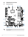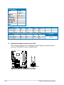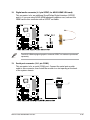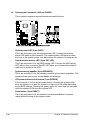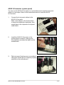
1
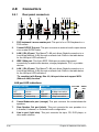
Motherboard
P5Q3 Deluxe/
WiFi-AP@n
E3783
First Edition V1
May 2008
Copyright © 2008 ASUSTeK COMPUTER INC. All Rights Reserved.
No part of this manual, including the products and software described in it, may be reproduced,
transmitted, transcribed, stored in a retrieval system, or translated into any language in any form or by any
means, except documentation kept by the purchaser for backup purposes, without the express written
permission of ASUSTeK COMPUTER INC. (“ASUS”).
Product warranty or service will not be extended if: (1) the product is repaired, modified or altered, unless
such repair, modification of alteration is authorized in writing by ASUS; or (2) the serial number of the
product is defaced or missing.
ASUS PROVIDES THIS MANUAL “AS IS” WITHOUT WARRANTY OF ANY KIND, EITHER EXPRESS
OR IMPLIED, INCLUDING BUT NOT LIMITED TO THE IMPLIED WARRANTIES OR CONDITIONS OF
MERCHANTABILITY OR FITNESS FOR A PARTICULAR PURPOSE. IN NO EVENT SHALL ASUS, ITS
DIRECTORS, OFFICERS, EMPLOYEES OR AGENTS BE LIABLE FOR ANY INDIRECT, SPECIAL,
INCIDENTAL, OR CONSEQUENTIAL DAMAGES (INCLUDING DAMAGES FOR LOSS OF PROFITS,
LOSS OF BUSINESS, LOSS OF USE OR DATA, INTERRUPTION OF BUSINESS AND THE LIKE),
EVEN IF ASUS HAS BEEN ADVISED OF THE POSSIBILITY OF SUCH DAMAGES ARISING FROM ANY
DEFECT OR ERROR IN THIS MANUAL OR PRODUCT.
SPECIFICATIONS AND INFORMATION CONTAINED IN THIS MANUAL ARE FURNISHED FOR
INFORMATIONAL USE ONLY, AND ARE SUBJECT TO CHANGE AT ANY TIME WITHOUT NOTICE,
AND SHOULD NOT BE CONSTRUED AS A COMMITMENT BY ASUS. ASUS ASSUMES NO
RESPONSIBILITY OR LIABILITY FOR ANY ERRORS OR INACCURACIES THAT MAY APPEAR IN THIS
MANUAL, INCLUDING THE PRODUCTS AND SOFTWARE DESCRIBED IN IT.
Products and corporate names appearing in this manual may or may not be registered trademarks or
copyrights of their respective companies, and are used only for identification or explanation and to the
owners’ benefit, without intent to infringe.
ii
Contents
Contents....................................................................................................... iii
Notices........................................................................................................... v
Safety information....................................................................................... vi
About this guide......................................................................................... vii
P5Q3 Deluxe/WiFi-AP@n specifications summary.................................. ix
Chapter 1:
Product introduction
1.1
Welcome!....................................................................................... 1-1
1.3
Special features............................................................................. 1-2
1.2
Package contents.......................................................................... 1-1
1.3.1
Product highlights............................................................ 1-2
1.3.3
ASUS Intelligent Performance
and Overclocking features............................................... 1-8
1.3.2
Chapter 1:
2.1
2.2
Motherboard overview.................................................................. 2-2
2.2.1
Motherboard layout.......................................................... 2-2
2.2.3
Placement direction......................................................... 2-4
2.2.4
Screw holes..................................................................... 2-4
2.3.1
Installing the CPU............................................................ 2-6
2.3.3
Uninstalling the CPU heatsink and fan.......................... 2-10
2.3.4
Installing the CPU heatsink and fan................................. 2-9
Installing the optional fans..............................................2-11
System memory.......................................................................... 2-12
2.4.1
Overview........................................................................ 2-12
2.4.3
Installing a DIMM........................................................... 2-14
2.4.2
2.5
Layout contents................................................................ 2-3
Central Processing Unit (CPU).................................................... 2-5
2.3.2
2.4
Hardware information
Before you proceed...................................................................... 2-1
2.2.2
2.3
ASUS AI Lifestyle unique features .................................. 1-4
2.4.4
Memory configurations................................................... 2-13
Removing a DIMM......................................................... 2-14
Expansion slots........................................................................... 2-15
2.5.1
Installing an expansion card.......................................... 2-15
2.5.3
Interrupt assignments.................................................... 2-16
2.5.2
Configuring an expansion card...................................... 2-15
iii
Contents
2.5.4
PCI slots......................................................................... 2-17
2.5.6
PCI Express 2.0 x16 slots.............................................. 2-17
2.5.5
2.6
2.7
2.8
2.9
2.10
2.5.7
Universal PCI Express x16 slot...................................... 2-17
Jumpers....................................................................................... 2-19
Onboard switches....................................................................... 2-21
Connectors.................................................................................. 2-22
2.8.1
2.8.2
Rear panel connectors................................................... 2-22
Internal connectors........................................................ 2-25
Starting up for the first time....................................................... 2-38
Turning off the computer............................................................ 2-39
2.10.1
2.10.2
iv
PCI Express x1 slots...................................................... 2-17
Using the OS shut down function................................... 2-39
Using the dual function power switch............................. 2-39
Notices
Federal Communications Commission Statement
This device complies with Part 15 of the FCC Rules. Operation is subject to the
following two conditions:
• This device may not cause harmful interference, and
• This device must accept any interference received including interference that
may cause undesired operation.
This equipment has been tested and found to comply with the limits for a
Class B digital device, pursuant to Part 15 of the FCC Rules. These limits are
designed to provide reasonable protection against harmful interference in a
residential installation. This equipment generates, uses and can radiate radio
frequency energy and, if not installed and used in accordance with manufacturer’s
instructions, may cause harmful interference to radio communications. However,
there is no guarantee that interference will not occur in a particular installation. If
this equipment does cause harmful interference to radio or television reception,
which can be determined by turning the equipment off and on, the user is
encouraged to try to correct the interference by one or more of the following
measures:
• Reorient or relocate the receiving antenna.
• Increase the separation between the equipment and receiver.
• Connect the equipment to an outlet on a circuit different from that to which the
receiver is connected.
• Consult the dealer or an experienced radio/TV technician for help.
The use of shielded cables for connection of the monitor to the graphics card is
required to assure compliance with FCC regulations. Changes or modifications
to this unit not expressly approved by the party responsible for compliance
could void the user’s authority to operate this equipment.
Canadian Department of Communications Statement
This digital apparatus does not exceed the Class B limits for radio noise emissions
from digital apparatus set out in the Radio Interference Regulations of the
Canadian Department of Communications.
This class B digital apparatus complies with Canadian ICES-003.
Safety information
Electrical safety
• To prevent electrical shock hazard, disconnect the power cable from the
electrical outlet before relocating the system.
• When adding or removing devices to or from the system, ensure that the
power cables for the devices are unplugged before the signal cables are
connected. If possible, disconnect all power cables from the existing system
before you add a device.
• Before connecting or removing signal cables from the motherboard, ensure
that all power cables are unplugged.
• Seek professional assistance before using an adpater or extension cord.
These devices could interrupt the grounding circuit.
• Make sure that your power supply is set to the correct voltage in your area.
If you are not sure about the voltage of the electrical outlet you are using,
contact your local power company.
• If the power supply is broken, do not try to fix it by yourself. Contact a
qualified service technician or your retailer.
Operation safety
• Before installing the motherboard and adding devices on it, carefully read all
the manuals that came with the package.
• Before using the product, make sure all cables are correctly connected and the
power cables are not damaged. If you detect any damage, contact your dealer
immediately.
• To avoid short circuits, keep paper clips, screws, and staples away from
connectors, slots, sockets and circuitry.
• Avoid dust, humidity, and temperature extremes. Do not place the product in
any area where it may become wet.
• Place the product on a stable surface.
• If you encounter technical problems with the product, contact a qualified
service technician or your retailer.
This symbol of the crossed out wheeled bin indicates that the product (electrical,
electronic equipment and mercury-containing button cell battery) should not
be placed in municipal waste. Check local regulations for disposal of electronic
products.
vi
About this guide
This user guide contains the information you need when installing and configuring
the motherboard.
How this guide is organized
This guide contains the following parts:
•
•
Chapter 1: Product introduction
This chapter describes the features of the motherboard and the new
technology it supports.
Chapter 2: Hardware information
This chapter lists the hardware setup procedures that you have to perform
when installing system components. It includes description of the switches,
jumpers, and connectors on the motherboard.
Where to find more information
Refer to the following sources for additional information and for product and
software updates.
1.
2.
ASUS websites
The ASUS website provides updated information on ASUS hardware and
software products. Refer to the ASUS contact information.
Optional documentation
Your product package may include optional documentation, such as warranty
flyers, that may have been added by your dealer. These documents are not
part of the standard package.
vii
Conventions used in this guide
To make sure that you perform certain tasks properly, take note of the following
symbols used throughout this manual.
DANGER/WARNING: Information to prevent injury to yourself
when trying to complete a task.
CAUTION: Information to prevent damage to the components
when trying to complete a task.
IMPORTANT: Instructions that you MUST follow to complete a
task.
NOTE: Tips and additional information to help you complete a
task.
Typography
Bold text
Indicates a menu or an item to select.
Italics
Used to emphasize a word or a phrase.
<Key> Keys enclosed in the less-than and greater-than sign
means that you must press the enclosed key.
Example: <Enter> means that you must press the
Enter or Return key.
<Key1+Key2+Key3>
If you must press two or more keys simultaneously, the
key names are linked with a plus sign (+).
Example: <Ctrl+Alt+D>
viii
Command
Means that you must type the command exactly
as shown, then supply the required item or value
enclosed in brackets.
Example: At the DOS prompt, type the command line:
afudos /i[filename]
afudos /iP5Q3DLX.ROM
P5Q3 Deluxe/WiFi-AP@n
specifications summary
CPU
LGA775 socket for Intel® Core™2 Quad /
Core™2 Extreme / Core™2 Duo / Pentium® dual-core /
Celeron® dual-core / Celeron® Processors
Compatible with Intel® 05B/05A/06 processors
Intel® next generation 45nm Multi-Core CPU
* Refer to www.asus.com for Intel CPU support list
Chipset
Intel® P45 / ICH10R with Intel® Fast Memory Access
Technology
System Bus
1600 / 1333 / 1066 / 800 MHz
Memory
4 x DIMM, max. 16GB, DDR3 1600/ 1333/ 1066/ 800 MHz, non-ECC, un-buffered memory
Dual channel memory architecture
Supports Intel® Extreme Memory Profile (XMP)
* Refer to www.asus.com or this user manual for the Memory QVL (Qualified Vendors Lists)
Expansion Slots
2 x PCI Express 2.0 x16 slots, support ATI CrossFireX™
Technology at x8 speed (PCIe 2.0 x16_1 blue,
PCIe 2.0 x16_2 black*)
1 x PCI Express x16 slot at max. x4 speed (black)**
2 x PCI Express x1 slots
2 x PCI slots
* PCIe 2.0 x16_2 slot (black, at max. x8 link)
**If any other PCI Express x1 slot is occupied, this slot
will downgrade to max. x1 speed.
Storage
Intel® ICH10R Southbridge:
- 6 x SATA 3.0 Gb/s ports
- Intel® Matrix Storage supporting SATA RAID 0,1,
5, and 10
Marvell 88SE6121 controller:
- 1 x Ultra DMA 133/100/66 for up to 2 PATA devices
- 1 x External SATA 3.0 Gb/s port (SATA On-the-Go)
Silicon Image SIL5723 controller (Drive Xpert
Technology):
- 2 x SATA 3.0 Gb/s ports
- Supports EZ Backup and Super Speed functions
LAN
Dual Gigabit LAN controllers
Marvell® 88E8056/88E8001 Gigabit LAN controller, featuring AI NET2, Teaming, Redundant
Wireless LAN
(WiFi-AP Edition only)
ASUS WiFi-AP@n
- 300 Mbps* IEEE 802.11n (Draft) and backwards compatible with IEEE 802.11g/b
- Software Access Point mode
*300 Mbps is IEEE 802.11n draft specification.
Actual throughput varies depending on the wireless environment and other parameters.
(continued on the next page)
ix
P5Q3 Deluxe/WiFi-AP@n
specifications summary
USB
10 x USB 2.0 ports (4 ports at mid-board, 6 ports at back
panel)
IEEE 1394
LSI® L-FW3227 1394a controller supports 2 x IEEE 1394a ports (one at midboard; one at back panel)
Audio
ADI® AD2000B 8-channel High Definition Audio CODEC
- Supports Jack-Detecting, Multi-streaming, and Front Panel Jack-Retasking technology
- Coaxial / Optical S/PDIF out ports at back I/O
- ASUS Noise Filter
ASUS AI Lifestyle
Unique features
ASUS Power Saving Solution:
- ASUS EPU-Six Engine
- ASUS 16-Phase Power Design
- ASUS AI Nap
AI Lifestyle Features:
- ASUS Express Gate SSD
- ASUS WiFi-AP@n
- ASUS AI Direct Link
ASUS Quiet Thermal Solution:
- ASUS Fanless Design: Heat-pipe solution
- ASUS Fanless Design: Stack Cool 2
- ASUS Fan Xpert
- ASUS Optional Fan for Water-cooling or
Passive-Cooling only
ASUS Crystal Sound:
- AI Audio 2
- ASUS Noise Filtering
ASUS EZ DIY:
- ASUS Drive Xpert
- DieHard BIOS
- ASUS Q-Shield
- ASUS Q-Connector
- ASUS O.C. Profile
- ASUS EZ Flash 2
BIOS Features
16 Mb AMI BIOS, PnP, DMI 2.0, WfM 2.0, SM BIOS
2.4, Multi-language BIOS
Manageability
WOL by PME, WOR by PME, WOR by Ring, Chassis Intrusion, PXE
ASUS Stylish Features
ASUS MyLogo 3
Multi-language BIOS
(continued on the next page)
P5Q3 Deluxe/WiFi-AP@n
specifications summary
ASUS Exclusive
Overclocking Features
ASUS AI Booster utility
Precision Tweaker 2:
- vCore: Adjustable CPU voltage at 0.00625V increment
- vDIMM: 64-step DRAM voltage control
- vChipset (N.B.): 48-step DRAM voltage control
- vCPU PLL: 64-step reference voltage control
- vFSB Termination: 40-step Front Side Bus voltage control
SFS (Stepless Frequency Selection)
- FSB tuning from 200MHz up to 800MHz at 1MHz
increment
- PCI Express frequency tuning from 100MHz up to
180MHz at 1MHz increment
Overclocking Protection:
- ASUS C.P.R.(CPU Parameter Recall)
Back Panel I/O Ports
1 x PS/2 Keyboard / Mouse combo port
1 x S/PDIF Out (Coaxial + Optical)
1 x External SATA
1 x IEEE1394a
2 x RJ45 ports
6 x USB 2.0/1.1
2 x WiFi-AP@n antenna jacks
8-channel Audio I/O
Internal I/O Connectors
2 x USB connectors support additional 4 USB ports
1 x Floppy disk drive connector
1 x COM connector
1 x IDE connector
6 x SATA connectors (red)
2 x Drive Xpert SATA connectors (Orange)
1 x CPU Fan connector
3 x Chassis Fan connectors
1 x Power Fan connector
1 x IEEE1394a connector
Front panel audio connector
1 x S/PDIF Out Header
Chassis Intrusion connector
CD audio in
24-pin ATX Power connector
8-pin ATX 12V Power connectors
System Panel (Q-Connector)
1 x Power on switch
1 x Reset switch
(continued on the next page)
xi
P5Q3 Deluxe/WiFi-AP@n
specifications summary
Support DVD Contents
Drivers
ASUS PC Probe II
ASUS Update
ASUS AI Suite
Image-Editing Suite
Anti-virus software (OEM version)
Form Factor
ATX Form Factor, 12”x 9.6” (30.5cm x 24.4cm)
*Specifications are subject to change without notice.
xii
This chapter describes the motherboard
features and the new technologies
it supports.
Chapter 1:
1
Product
introduction
Chapter summary
1
1.1
Welcome!....................................................................................... 1-1
1.3
Special features............................................................................. 1-2
1.2
Package contents.......................................................................... 1-1
ASUS P5Q3 Deluxe/WiFi-AP@n
1.1
Welcome!
Thank you for buying an ASUS® P5Q3 Deluxe/WiFi-AP@n motherboard!
The motherboard delivers a host of new features and latest technologies, making it
another standout in the long line of ASUS quality motherboards!
Before you start installing the motherboard, and hardware devices on it, check the
items in your package with the list below.
1.2
Package contents
Check your motherboard package for the following items.
Motherboard
ASUS P5Q3 Deluxe/WiFi-AP@n
Cables
1 x Serial ATA power cable for 2 devices
6 x Serial ATA signal cables
1 x Ultra DMA 133/100/66 cable
1 x Floppy disk drive cable
Application DVD
ASUS motherboard support DVD
I/O modules
Accessories
Documentation
1 x Multi-function module (1-port IEEE 1394a and 2-port USB 2.0 module)
ASUS Q-Shield (I/O shield)
1 x ASUS Optional Fans for Water-Cooling or
Passive-Cooling only
1 x ASUS Q-Connector Kit (USB, 1394, system
panel; Retail version only)
2 x WiFi-AP@n omni-directional antennae
User guide
ASUS WiFi-AP@n manual
If any of the above items is damaged or missing, contact your retailer.
ASUS P5Q3 Deluxe/WiFi-AP@n
1-
1.3
Special features
1.3.1
Product highlights
Green ASUS
This motherboard and its packaging comply with the European Union’s Restriction
on the use of Hazardous Substances (RoHS). This is in line with the ASUS vision
of creating environment-friendly and recyclable products/packagings to safeguard
consumers’ health while minimizing the impact on the environment.
Intel® Core™2 Extreme / Core™ 2 Quad /
Core™2 Duo Processor Support
This motherboard supports the latest Intel® Core™ 2 Extreme / Core™ 2 Quad /
Core™ 2 Duo processors in the LGA775 package. It is excellent for multi-tasking,
multi-media and enthusiastic gamers with 1600 / 1333 / 1066 / 800 MHz FSB. The
Intel® Core™ 2 series processor is one of the most powerful CPUs in the world.
This motherboard also supports Intel® CPUs in the new 45nm manufacturing
process.
Intel P45 Chipset
The Intel® P45 Express Chipset is the latest chipset designed to support 16GB of
dual-channel DDR3 1600/ 1333/ 1066/ 800 architecture, 1600/ 1333/ 1066/ 800
FSB (Front Side Bus), PCIe 2.0, and multi-core CPUs. It especially includes Intel®
Fast Memory Access technology that significantly optimizes the use of available
memory bandwidth and reduces the latency of the memory accesses.
DDR3 memory support
The motherboard supports DDR3 memory that features data transfer rates of
1600 /1333 / 1066 / 800 MHz to meet the higher bandwidth requirements of the
latest 3D graphics, multimedia, and Internet applications. The dual-channel DDR3
architecture doubles the bandwidth of your system memory to boost system
performance. Furthermore, this motherboard does not restrict the memory size
across two channels. Users may install different memory size DIMMs into the two
channels and enjoy dual-channel and single-channel functions at the same time.
This new feature optimizes the use of available memory size. See page 2-13 for
details.
1-
Chapter 1: Product Introduction
PCIe 2.0
This motherboard supports the latest PCIe 2.0 device for twice the current speed
and bandwidth. This enhances system performance while still providing backward
compatibility to PCIe 1.0 devices. See page 2-17 for details.
Serial ATA 3 Gb/s technology and SATA-On-The-Go
This motherboard supports the next-generation hard drives based on the Serial ATA
(SATA) 3 Gb/s storage specification, delivering enhanced scalability and doubling
the bus bandwidth for high-speed data retrieval and saves. The external SATA port
located at the back I/O provides smart setup and hot-plug functions. Easily backup
photos, videos and other entertainment contents to external devices. See pages
2-23, 2-27, and 2-28 for details.
IEEE 1394a support
The IEEE 1394a interface provides high speed digital interface for audio/video
appliances such as digital television, digital video camcorders, storage peripherals &
other PC portable devices. See pages 2-22 and 2-29 for details.
S/PDIF digital sound ready
This motherboard provides convenient connectivity to external home theater audio
systems via coaxial and optical S/PDIF-out (SONY-PHILIPS Digital Interface)
jacks.It allows to transfer digital audio without converting to analog format and
keeps the best signal quality. See pages 2-22 and 2-35 for details.
Dual Gigabit LAN solution
The integrated dual Gigabit LAN design allows a PC to serve as a network
gateway for managing traffic between two separate networks. This capability
ensures rapid transfer of data from WAN to LAN without any added arbitration or
latency. See page 2-22 for details.
High Definition Audio
Enjoy high-end sound quality on your PC! The onboard 8-channel HD audio (High
Definition Audio, previously codenamed Azalia) CODEC enables high-quality
192KHz/24-bit audio output that simultaneously sends different audio streams to
different destinations. You can now talk to your partners on the headphone while
playing multi-channel network games. See pages 2-22 and 2-23 for details.
ASUS P5Q3 Deluxe/WiFi-AP@n
1-
1.3.2
ASUS AI Lifestyle unique features
ASUS Express Gate SDD
Taking only 5 seconds to go online from bootup, Express Gate is the one-stop
gateway to instant fun! It's a unique motherboard built-in OS. You can utilize the
most popular Instant Messengers (IM) like MSN, Skype, Google talk, QQ, and
Yahoo! Messenger to keep in touch with friends, or quickly check on the weather
and e-mails just before leaving your house. What's more, the user-friendly picture
manager lets you view your pictures without entering Windows at anytime!
The actual boot depends on the system configurations.
ASUS WiFi-AP@n
With spec 300 Mbps transfer rates, WiFi-AP@n supports the latest WiFi
specifications, 802.11n (draft), for better signal coverage, stronger signals and
faster data transmissions in comparison to previous 802.11b/g standards. With two
antennas, you will not suffer from signal loss like before. You can also enjoy the
choice to set the device in AP-Mode or Client Mode. Refer to the bundled ASUS
WiFi-AP@n manual for more details.
AI Direct Link
AI Direct Link can easily and efficiently transfer large amounts of data via the
network cable - saving up to 70% of the total time taken. With AI Direct Link, it
becomes easy to backup or share large data files like movies or other media
content.
ASUS Power Saving Solution
ASUS Power Saving solution intelligently and automatically provides balanced
computing power and energy consumption.
ASUS EPU-6 Engine
The new ASUS EPU - the world's first power saving engine, has been
upgraded to a new six engine version, which provides total system power
savings by detecting current PC loadings and intelligently moderating power
in real-time. With auto phase switching for components (which includes
the CPU, VGA card, memory, chipset, drives and system fan), the EPU
automatically provides the most appropriate power usage via intelligent
acceleration and overclocking - helping save power and money.
1-
Chapter 1: Product Introduction
ASUS 16-Phase Power Design
The breakthrough technology of 16-phase VRM design is bringing to the
ASUS motherboards. 16-phase power design can reach the power efficiency
up to 96%+, and dispel heat generated by VRM module effectively, and lower
temperature 36°C+ compared to other VRM solution. With all Japanese-made
best quality power components such as low RDS (on) MOSFETs, Ferrite
core chokes with lower hysteresis loss, and high quality conductive polymer
capacitors, ASUS 16-phase VRM design also ensure longer component life,
minimum power loss, and help to reach the superior overclocking score ever
than before.
AI Nap
With AI Nap, the system can continue running at minimum power and noise
when you are temporarily away. To wake the system and return to the OS
environment, simply click the mouse or press a key.
ASUS Quiet Thermal Solution
ASUS Quiet Thermal solution makes system more stable and enhances the
overclocking capability.
Fanless Design - Stack Cool 2
ASUS Stack Cool 2 is a fan-less and zero-noise cooling solution that lowers
the temperature of critical heat generating components. The motherboard
uses a special design on the printed circuit board (PCB) to dissipate heat
these critical components generate.
Fanless Design - Pure Copper Heat-pipe
The Heat Pipe design effectively directs the heat generated by the chipsets to
the heatsink near the back IO ports, where it can be carried away by existing
airflow from CPU fan or bundled optional fan. The purpose of the innovative
heat pipe design on this motherboard is that the groundbreaking fanless
design does not have lifetime problems as a chipset fan does. Furthermore, it
provides options for users to install side-flow fan or passive cooler. The Heat
Pipe design is the most reliable fanless thermal solution to date.
DO NOT uninstall the heat-pipe by yourself. Doing so may bend the tubing and
affect the heat dissipation performance.
For optimal cooling performance, remove the protect film attached on the
ICH10R southbridge before use.
ASUS P5Q3 Deluxe/WiFi-AP@n
1-
Optional Fan (for Water-Cooling or Passive-Cooling only)
The optional fan is specifically designed to provide sufficient airflow over the
CPU power modules and chipset area when water-cooling or passive-cooling
is utilized, ensuring effective heat dissipation for the entire system. See page
2-38 for details.
Fan Xpert
ASUS Fan Xpert intelligently allows users to adjust both the CPU and chassis
fan speed according to different ambient temperature, which is caused
by different climate conditions in different geographic regions and system
loading. Built-in variety of useful profiles offer flexible controls of fan speed to
achieve a quiet and cool environment.
ASUS Crystal Sound
This feature can enhance speech-centric applications like Skype, online game,
video conference and recording.
AI Audio 2
AI Audio 2 creates a virtual center channel that expands the overall sound
field without introducing a picket fencing effect. Preserving the dialogue or
solo performances with downmixing from multichannels will allow you to
experience true-to-life high quality audio.
Noise Filter
This feature detects repetitive and stationary noises (non-voice signals) like
computer fans, air conditioners, and other background noises then eliminates
it in the incoming audio stream while recording.
ASUS EZ DIY
ASUS EZ DIY feature collection provides you easy ways to install computer
components, update the BIOS or back up your favorite settings.
ASUS Drive Xpert
Without drivers or BIOS setups, the ASUS exclusive Drive Xpert is ideal for
anyone who needs to secure data on their hard drives or enhance hard drive
performances without the hassles of complicated configurations. With Drive
Xpert’s user-friendly graphical user interface, users can easily arrange hard
drive backups or enhance their hard drive transfer rates - making sure that
data is looked after every moment, every day.
1-
Chapter 1: Product Introduction
ASUS Q-Shield
The specially designed ASUS Q-Shield provides conductivity to best protect
your motherboard against static electricity damage and shields it against
Electronic Magnetic Interference (EMI). Without the usual "fingers" present,
this new design is convenient and safe to install.
ASUS Q-Connector
ASUS Q-Connector allows you to easily connect or disconnect the chassis
front panel cables to the motherboard. This unique module eliminates the
trouble of connecting the system panel cables one at a time and avoiding
wrong cable connections. See page 2-37 for details.
ASUS O.C. Profile
The motherboard features the ASUS O.C. Profile that allows users to
conveniently store or load multiple BIOS settings. The BIOS settings can be
stored in the CMOS or a separate file, giving users freedom to share and
distribute their favorite settings.
ASUS DieHard BIOS
The AUS DieHard BIOS consists of two BIOS chips, a main BIOS and a
backup BIOS. The ASUS DieHard BIOS can restore corrupted main BIOS
data from the backup BIOS automatically. The technology saves users the
hassle of recovering the BIOS file or buying a replacement BIOS chip.
ASUS EZ Flash 2
EZ Flash 2 is a user-friendly BIOS update utility. Simply press the predefined
hotkey to launch the utility and update the BIOS without entering the OS.
Update your BIOS easily without preparing a bootable diskette or using an
OS-based flash utility.
ASUS MyLogo3™
This feature allows you to convert your favorite photo into a 256-color boot logo for
a more colorful and vivid image on your screen.
ASUS P5Q3 Deluxe/WiFi-AP@n
1-
ASUS Multi-language BIOS
The multi-language BIOS allows you to select the language of your choice from the
available options. The localized BIOS setup menu helps you configure your system
easier and faster.
1.3.3
ASUS Intelligent Performance and Overclocking
features
AI Booster
The ASUS AI Booster allows you to overclock the CPU speed in Windows
environment without the hassle of booting the BIOS.
Precision Tweaker 2
Allows the user to adjust the NB Voltage, FSB termination Voltage, CPU PLL
Voltage and the DRAM Voltage in 0.02v steps to finetune voltages to achieve the
most precise setting for the ultimate customized overclocking configuration.
C.P.R. (CPU Parameter Recall)
The C.P.R. feature of the motherboard BIOS allows automatic re-setting to the
BIOS default settings in case the system hangs due to overclocking. When the
system hangs due to overclocking, C.P.R. eliminates the need to open the system
chassis and clear the RTC data. Simply shut down and reboot the system, and the
BIOS automatically restores the CPU default setting for each parameter.
1-
Chapter 1: Product Introduction
This chapter lists the hardware setup
procedures that you have to perform
when installing system components. It
includes description of the jumpers and
connectors on the motherboard.
Chapter 1:
2
Hardware
information
Chapter summary
2
2.1
Before you proceed...................................................................... 2-1
2.3
Central Processing Unit (CPU).................................................... 2-5
2.2
2.4
2.5
2.6
2.7
2.8
2.9
2.10
Motherboard overview.................................................................. 2-2
System memory.......................................................................... 2-12
Expansion slots........................................................................... 2-15
Jumpers....................................................................................... 2-19
Onboard switches....................................................................... 2-21
Connectors.................................................................................. 2-22
Starting up for the first time....................................................... 2-38
Turning off the computer............................................................ 2-39
ASUS P5Q3 Deluxe/WiFi-AP@n
2.1
Before you proceed
Take note of the following precautions before you install motherboard components
or change any motherboard settings.
•
Unplug the power cord from the wall socket before touching any
component.
•
Use a grounded wrist strap or touch a safely grounded object or
a metal object, such as the power supply case, before handling
components to avoid damaging them due to static electricity.
•
Hold components by the edges to avoid touching the ICs on them.
•
Whenever you uninstall any component, place it on a grounded
antistatic pad or in the bag that came with the component.
•
Before you install or remove any component, ensure
that the ATX power supply is switched off or the power cord is detached
from the power supply. Failure to do so may cause severe damage to the
motherboard, peripherals, and/or components.
ASUS P5Q3 Deluxe/WiFi-AP@n
2-
2.2
Motherboard overview
2.2.1
Motherboard layout
Refer to 2.8 Connectors for more information about rear panel connectors and
internal connectors.
2-
Chapter 2: Hardware information
2.2.2
Layout contents
Connectors/Jumpers/Slots
Page
1.
ATX power connectors (24-pin EATXPWR, 8-pin EATX12V)
2-32
3.
CPU, Chassis, and Power Fan connectors (4-pin CPU_FAN,
3-pin PWR_FAN, 3-pin CHA_FAN1-3)
2-30
2.
4.
5.
6.
7.
8.
9.
10.
11.
12.
13.
14.
15.
16.
17.
18.
19.
20.
LGA775 CPU Socket
2-6
DDR3 DIMM slots
2-12
Chassis intrusion connector (4-1 pin CHASSIS)
2-31
ICH10R Serial ATA connectors [red] (7-pin SATA1-6)
2-27
CPU / Northbridge overvoltage setting (3-pin OV_CPU; 3-pin
OV_NB)
Floppy disk drive connector (34-1 pin FLOPPY)
IDE connector (40-1 pin PRI_IDE)
SIL5723 Serial ATA connectors
(7-pin SATA_E1-2)
2-20
2-25
2-26
2-28
Clear RTC RAM (3-pin CLRTC)
2-19
Onboard switches (Power-on switch, Reset switch)
2-21
System panel connector (20-8 pin PANEL)
USB connectors (10-1 pin USB 78, USB 910)
Serial port connector (10-1 pin COM1)
IEEE 1394a port connector (10-1 pin IE1394_2)
Optical drive audio connector (4-pin CD)
Front panel audio connector (10-1 pin AAFP)
Digital audio connector (4-1 pin SPDIF_OUT, for ASUS HDMI
VGA card)
2-36
2-29
2-35
2-29
2-34
2-31
2-35
Express_Gate SSD
ASUS P5Q3 Deluxe/WiFi-AP@n
2-
2.2.3
Placement direction
When installing the motherboard, make sure that you place it into the chassis in the
correct orientation. The edge with external ports goes to the rear part of the chassis
as indicated in the image below.
2.2.4
Screw holes
Place nine (9) screws into the holes indicated by circles to secure the motherboard
to the chassis.
DO NOT overtighten the screws! Doing so can damage the motherboard.
Place this side towards
the rear of the chassis
2-
Chapter 2: Hardware information
2.3
Central Processing Unit (CPU)
The motherboard comes with a surface mount LGA775 socket designed for the
Intel® Core™2 Quad / Core™2 Extreme / Core™2 Duo / Pentium® dual-core /
Celeron® dual-core / Celeron® Processors.
•
Make sure that all power cables are unplugged before installing the CPU.
•
If installing a dual-core CPU, connect the chassis fan cable to the
CHA_FAN1 connector to ensure system stability.
•
Due to the chipset limitation, we recommend you use FSB 800MHz CPU or
above.
•
Upon purchase of the motherboard, make sure that the PnP cap is on
the socket and the socket contacts are not bent. Contact your retailer
immediately if the PnP cap is missing, or if you see any damage to the PnP
cap/socket contacts/motherboard components. ASUS will shoulder the cost
of repair only if the damage is shipment/transit-related.
•
•
Keep the cap after installing the motherboard. ASUS will process Return
Merchandise Authorization (RMA) requests only if the motherboard comes
with the cap on the LGA775 socket.
The product warranty does not cover damage to the socket contacts
resulting from incorrect CPU installation/removal, or misplacement/loss/
incorrect removal of the PnP cap.
ASUS P5Q3 Deluxe/WiFi-AP@n
2-
2.3.1
Installing the CPU
To install a CPU:
1.
Locate the CPU socket on the motherboard.
Before installing the CPU, make sure that the cam box is facing towards you
and the load lever is on your left.
2.
Press the load lever with your thumb
(A), then move it to the left (B) until it
is released from the retention tab.
To prevent damage to the socket
pins, do not remove the PnP cap
unless you are installing a CPU.
3.
4.
Retention tab
A
B
Load lever
Lift the load lever in the direction of
the arrow to a 135º angle.
PnP cap
Load plate
Lift the load plate with your thumb
and forefinger to a 100º angle (4A),
then push the PnP cap from the
load plate window to remove (4B).
4B
4A
3
2-
Chapter 2: Hardware information
5.
Position the CPU over the socket,
making sure that the gold triangle
is on the bottom‑left corner of the
socket then fit the socket alignment
key into the CPU notch.
CPU notch
Gold
triangle
mark
The CPU fits in only one correct
orientation. DO NOT force the
CPU into the socket to prevent
bending the connectors on the
socket and damaging the CPU!
Alignment key
6.
Apply several drops of thermal paste
to the exposed area of the CPU that
the heatsink will be in contact with,
ensuring that it is spread in an even
thin layer.
Some heatsinks come with preapplied thermal paste. If so, skip
this step.
The Thermal Interface Material is toxic and inedible. If it gets into your eyes
or touches your skin, ensure to wash it off immediately, and seek professional
medical help.
To prevent contaminating the paste, DO NOT spread the paste with your finger
directly.
ASUS P5Q3 Deluxe/WiFi-AP@n
2-
7.
Close the load plate (A), then push
the load lever (B) until it snaps into
the retention tab.
A
B
The motherboard supports Intel® LGA775 processors with the Intel® Enhanced
Memory 64 Technology (EM64T), Enhanced Intel SpeedStep® Technology
(EIST), and Hyper-Threading Technology. Refer to the Appendix for more
information on these CPU features.
2-
Chapter 2: Hardware information
2.3.2
Installing the CPU heatsink and fan
The Intel LGA775 processor requires a specially designed heatsink and fan
assembly to ensure optimum thermal condition and performance.
®
•
When you buy a boxed Intel® processor, the package includes the CPU fan
and heatsink assembly. If you buy a CPU separately, make sure that you
use only Intel®‑certified multi‑directional heatsink and fan.
•
Your Intel® LGA775 heatsink and fan assembly comes in a push-pin design
and requires no tool to install.
•
If you purchased a separate CPU heatsink and fan assembly, make sure
that you have properly applied Thermal Interface Material to the CPU
heatsink or CPU before you install the heatsink and fan assembly.
Make sure that you have installed the motherboard to the chassis before you
install the CPU fan and heatsink assembly.
If you purchased a separate CPU heatsink and fan assembly, ensure that the
Thermal Interface Material is properly applied to the CPU heatsink or CPU
before you install the heatsink and fan assembly.
To install the CPU heatsink and fan:
1.
2.
Place the heatsink on top of the
installed CPU, making sure that the
four fasteners match the holes on
the motherboard.
A
B
B
A
Push down two fasteners at a time
in a diagonal sequence to secure
the heatsink and fan assembly in
place.
A
B
B
A
1
1
Orient the heatsink and fan assembly such that the CPU fan cable is closest to
the CPU fan connector.
ASUS P5Q3 Deluxe/WiFi-AP@n
2-
3.
Connect the CPU fan cable to the connector on the motherboard labeled
CPU_FAN.
DO NOT forget to connect the CPU fan connector! Hardware monitoring errors
can occur if you fail to plug this connector.
2.3.3
Uninstalling the CPU heatsink and fan
To uninstall the CPU heatsink and fan:
A
1. Disconnect the CPU fan cable from
the connector on the motherboard.
2.
3.
4.
2-10
Rotate each fastener
counterclockwise.
Pull up two fasteners at a time in a
diagonal sequence to disengage the
heatsink and fan assembly from the
motherboard.
A
B
B
A
B
B
A
Carefully remove the heatsink and fan assembly from the motherboard.
Chapter 2: Hardware information
2.3.4
Installing the optional fans
Install the optional fan only if you are using a passive cooler or a water cooler.
Installing the optional fan with an active CPU cooler will interfere with the airflow
and destabilize the system.
1. Position the fan above the pipe
and heatsink assembly.
2. Fit the fan to the grooved edge of
the heatsink.
3. Carefully push down the fan until
it snugly fits the heatsink, then
connect the fan cable.
4. The photo shows the fan installed
on the motherboard.
•
Plug the optional fan cable to the CHA_FAN1/2 connector on the
motherboard.
•
Make sure the optional fan is installed correctly to prevent damage to the
fan and motherboard components.
ASUS P5Q3 Deluxe/WiFi-AP@n
2-11
2.4
System memory
2.4.1
Overview
The motherboard comes with four Double Data Rate 3 (DDR3) Dual Inline Memory
Modules (DIMM) sockets.
A DDR3 module has the same physical dimensions as a DDR2 DIMM but is
notched differently to prevent installation on a DDR2 DIMM socket. DDR3 modules
are developed for better performance with less power consumption.
The figure illustrates the location of the DDR3 DIMM sockets:
Channel
Channel A
Channel B
2-12
Sockets
DIMM_A1 and DIMM_A2
DIMM_B1 and DIMM_B2
Chapter 2: Hardware information
2.4.2
Memory configurations
You may install 1GB, 2GB and 4GB unbuffered and non‑ECC DDR3 DIMMs into
the DIMM sockets.
•
You may install varying memory sizes in Channel A and Channel B. The
system maps the total size of the lower-sized channel for the dual-channel
configuration. Any excess memory from the higher-sized channel is then
mapped for single-channel operation.
•
It is recommended to install the memory modules from the yellow slots for
better overclocking capability.
•
Always install DIMMs with the same CAS latency. For optimum
compatibility, it is recommended that you obtain memory modules from the
same vendor.
•
If you install four 1 GB memory modules, the system may only recognize
less than 3GB because the address space is reserved for other critical
functions. This limitation appears on Windows® XP/Vista 32-bit operation
system which does not support Physical Address Extension (PAE).
•
If you install Windows® XP/Vista 32-bit operation system, a total memory of
less than 3GB is recommended.
•
This motherboard does not support memory modules made up of 128 Mb
chips.
•
Due to chipset limitation, this motherboard can only support up to 16 GB
on the operating systems listed below. You may install a maximum of 4 GB
DIMMs on each slot.
64-bit
Windows XP Professional x64 Edition
Windows® Vista x64 Edition
®
•
The default memory operation frequency is dependent on its SPD. Under
the default state, some memory modules for overclocking may operate at a
lower frequency than the vendor-marked value.
•
The memory modules may require a better cooling system to work stably
under full loading (4 DIMMs) or overclocking setting.
ASUS P5Q3 Deluxe/WiFi-AP@n
2-13
2.4.3
Installing a DIMM
Make sure to unplug the power supply before adding or removing DIMMs or other
system components. Failure to do so may cause severe damage to both the
motherboard and the components.
1.
2.
2
Unlock a DIMM socket by
pressing the retaining clips
outward.
DIMM notch
Align a DIMM on the socket
such that the notch on the DIMM
matches the break on the socket.
1
1
Unlocked retaining clip
A DIMM is keyed with a notch so that it fits in only one direction. DO NOT force a
DIMM into a socket to avoid damaging the DIMM.
3.
Firmly insert the DIMM into the
socket until the retaining clips snap
back in place and the DIMM is
properly seated.
3
Locked Retaining Clip
2.4.4
Removing a DIMM
2
Follow these steps to remove a DIMM.
1.
Simultaneously press the
retaining clips outward to unlock
the DIMM.
1
1
DIMM notch
Support the DIMM lightly with your fingers when pressing the retaining clips. The
DIMM might get damaged when it flips out with extra force.
2.
2-14
Remove the DIMM from the socket.
Chapter 2: Hardware information
2.5
Expansion slots
In the future, you may need to install expansion cards. The following sub‑sections
describe the slots and the expansion cards that they support.
Make sure to unplug the power cord before adding or removing expansion
cards. Failure to do so may cause you physical injury and damage motherboard
components.
2.5.1
Installing an expansion card
To install an expansion card:
1.
2.
3.
4.
5.
6.
Before installing the expansion card, read the documentation that came with
it and make the necessary hardware settings for the card.
Remove the system unit cover (if your motherboard is already installed in a
chassis).
Remove the bracket opposite the slot that you intend to use. Keep the screw
for later use.
Align the card connector with the slot and press firmly until the card is
completely seated on the slot.
Secure the card to the chassis with the screw you removed earlier.
Replace the system cover.
2.5.2
Configuring an expansion card
After installing the expansion card, configure it by adjusting the software settings.
1.
2.
3.
Turn on the system and change the necessary BIOS settings, if any. See
Chapter 3 for information on BIOS setup.
Assign an IRQ to the card. Refer to the tables on the next page.
Install the software drivers for the expansion card.
When using PCI cards on shared slots, ensure that the drivers support “Share
IRQ” or that the cards do not need IRQ assignments. Otherwise, conflicts will arise
between the two PCI groups, making the system unstable and the card inoperable.
Refer to the table on the next page for details.
ASUS P5Q3 Deluxe/WiFi-AP@n
2-15
2.5.3
Interrupt assignments
Standard interrupt assignments
IRQ
Priority
Standard function
1
2
Keyboard Controller
0
2
1
–
4
12
6
14
5
7
8
9
10
11
12
13
14
13
15
3
4
5
6
7
8
9
System Timer
Redirect to IRQ#9
Communications Port (COM1)*
IRQ Holder for PCI Steering*
Floppy Disk Controller
Reserved
System CMOS/Real Time Clock
IRQ Holder for PCI Steering*
IRQ Holder for PCI Steering*
IRQ Holder for PCI Steering*
Reserved
Numeric Data Processor
Primary IDE Channel
* These IRQs are usually available for PCI devices.
IRQ assignments for this motherboard
PCIE1_1
PCIE1_2
PCIE16_1
PCIE16_2
PCIE16_3
LAN (8056)
LAN (8001)
Marvell 6121
PCI_1
PCI_2
USB controller 1
USB controller 2
USB controller 3
USB controller 4
USB controller 5
USB controller 6
USB 2.0 controller 1
USB 2.0 controller 2
SATA controller 1
SATA controller 2
Audio Azalia
2-16
A
B
C
D
–
–
shared
–
–
–
–
shared
shared
–
–
–
shared
–
–
–
shared
–
–
–
–
shared
–
–
–
–
shared
–
shared
–
–
–
shared
–
–
–
–
shared
–
–
–
–
–
–
–
–
–
shared
–
–
shared
–
shared
–
–
–
shared
–
–
–
–
–
–
–
–
–
–
–
–
–
shared
–
–
–
shared
–
–
–
–
shared
–
–
–
–
E
–
–
–
–
–
–
–
–
–
–
–
–
–
–
–
–
–
–
–
–
–
F
G
H
–
–
–
–
–
–
–
–
–
–
–
–
–
–
–
–
–
–
–
–
–
–
–
–
–
–
–
–
–
–
–
–
shared
–
–
–
–
–
–
–
–
–
–
–
–
shared
–
–
–
–
shared
–
–
–
–
–
–
–
–
–
–
shared
–
Chapter 2: Hardware information
2.5.4
PCI slots
The PCI slots support cards such as a LAN card, SCSI card, USB card, and other
cards that comply with PCI specifications. Refer to the figure below for the location
of the slot.
2.5.5
PCI Express x1 slots
This motherboard supports PCI Express x1 network cards, SCSI cards and other
cards that comply with the PCI Express specifications. Refer to the figure below for
the location of the slot.
2.5.6
PCI Express 2.0 x16 slots
This motherboard has two PCI Express 2.0 x16 slots that support PCI Express x16
2.0 graphic cards complying with the PCI Express specifications. Refer to the figure
below for the location of the slots.
2.5.7
Universal PCI Express x16 slot
This motherboard also supports one Universal PCI Express x16 slot with a
maximum speed of x4 link. Refer to the figure below for the location of the slot.
PCI Express x1_1 slot
PCI slot 1
PCIe 2.0 x16_1 slot (blue, @x16)
Universal PCIe x16_3 slot (black, at max. x4 link)
PCIe 2.0 x16_2 slot (black, at max. x8 link)
PCI slot 2
PCI Express x1_2 slot
ASUS P5Q3 Deluxe/WiFi-AP@n
2-17
2-18
•
In single VGA card mode, use first the PCIe 2.0 x16_1 slot (blue) for a PCI
Express x16 graphics card to get better performance.
•
In CrossFireX™ mode, use the PCIe 2.0 x16_1 (blue) and PCIe 2.0 x16_2
(black) slots for PCI Express x16 graphics cards to get better performance.
•
Use the two PCIe 2.0 x16 slots and the universal PCIe x16 slot for 3-Way
CrossFireX™ mode.
•
We recommend that you provide sufficient power when running
CrossFireX™ mode. See page 2-32 for details.
•
If one of the PCIe x1 slots is occupied, the universal PCI Express x16 slot
(black) will downgrade to max. x1 speed.
•
Connect a chassis fan to the motherboard connector labeled
CHA_FAN1/2/3 when using multiple graphics cards for better thermal
environment. See page 2-30 for details.
Chapter 2: Hardware information
2.6
1.
Jumpers
Clear RTC RAM (CLRTC)
This jumper allows you to clear the Real Time Clock (RTC) RAM in CMOS.
You can clear the CMOS memory of date, time, and system setup parameters
by erasing the CMOS RTC RAM data. The onboard button cell battery
powers the RAM data in CMOS, which include system setup information such
as system passwords.
To erase the RTC RAM:
1. Turn OFF the computer and unplug the power cord.
2. Remove the onboard battery.
3. Move the jumper cap from pins 1-2 (default) to pins 2-3. Keep the cap on
pins 2-3 for about 5-10 seconds, then move the cap back to pins 1-2.
4. Reinstall the battery.
5. Plug the power cord and turn ON the computer.
6. Hold down the <Del> key during the boot process and enter BIOS setup
to re-enter data.
Except when clearing the RTC RAM, never remove the cap on CLRTC jumper
default position. Removing the cap will cause system boot failure!
•
You do not need to clear the RTC when the system hangs due to
overclocking. For system failure due to overclocking, use the C.P.R. (CPU
Parameter Recall) feature. Shut down and reboot the system so the BIOS
can automatically reset parameter settings to default values.
•
Due to the chipset behavior, AC power off is required to enable C.P.R.
function. You must turn off and on the power supply or unplug and plug the
power cord before rebooting the system.
ASUS P5Q3 Deluxe/WiFi-AP@n
2-19
2.
CPU / Northbridge overvoltage setting (3-pin OV_CPU, 3-pin OV_NB)
These jumpers allow you to enable or disable the advanced CPU and
Northbridge overvoltage settings in BIOS. Read the following information
before you change the jumper settings. Set to pins 1-2 to activate the
advanced CPU / Northbridge overvoltage feature.
Pins 2-3 (Default)
Pins 1-2 (OV Enabled)
2-20
OV_CPU
OV_NB
up to 2.10V
up to 2.21V
up to 1.70V
up to 1.91V
•
Before you change the jumper settings for extra-high overvoltage ability,
use the BIOS items first to adjust the desired CPU and Northbridge
performance. Make sure your system functions well under the highest BIOS
voltage settings before you change the setting of these two jumpers.
•
DO NOT set the OV_CPU jumper to pins 1-2 when you install a new CPU
and have not booted for the first time. Doing so may cause the system to
halt. For system failure due to the wrong setting of the OV_CPU jumper,
shut down the computer and move the cap back to pins 2-3.
•
The system may need a better cooling system (for example, a water-cooling
system) to work stably under high voltage settings.
Chapter 2: Hardware information
2.7
Onboard switches
Onboard switches allow you to fine-tune performance when working on a bare
or open-case system. This is ideal for overclockers and gamers who continually
change settings to enhance system performance.
1.
2.
Power-on switch
Press the power-on switch to wake/power up the system.
Reset switch
Press the reset switch to reboot the system.
ASUS P5Q3 Deluxe/WiFi-AP@n
2-21
2.8
Connectors
2.8.1
Rear panel connectors
1.
2.
3.
4.
5.
PS/2 keyboard / mouse combo port. This port is for a PS/2 keyboard or a
PS/2 mouse.
Coaxial S/PDIF Out port. This port connects an external audio output device
via a coaxial S/PDIF cable.
LAN 2 (RJ-45) port. This Marvell® LAN port allows Gigabit connection to a
Local Area Network (LAN) through a network hub. Refer to the table below
for the LAN port LED indications.
IEEE 1394a port. This 6-pin IEEE 1394a port provides high-speed
connectivity for audio/video devices, storage peripherals, PCs, or portable
devices.
LAN 1 (RJ-45) port. This Marvell® LAN port allows Gigabit connection to a
Local Area Network (LAN) through a network hub. Refer to the table below
for the LAN port LED indications.
*To compliant with Energy Star 4.0, this port does not support WOL
(Wake on LAN) function.
LAN port LED indications
Activity Link LED
Status
Description
OFF
No link
ORANGE
Linked
BLINKING
Data activity
Speed LED
Status
OFF
ORANGE
GREEN
Description
10 Mbps connection
100 Mbps connection
1 Gbps connection
ACT/LINK
LED
SPEED
LED
LAN port
6. Center/Subwoofer port (orange). This port connects the center/subwoofer
speakers.
7.
8.
2-22
Rear Speaker Out port (black). This port connects the rear speakers in a
4-channel, 6-channel, or 8-channel audio configuration..
Line In port (light blue). This port connects the tape, CD, DVD player, or
other audio sources.
Chapter 2: Hardware information
9.
Line Out port (lime). This port connects a headphone or a speaker. In
4-channel, 6-channel, and 8-channel configuration, the function of this port
becomes Front Speaker Out.
10. Wireless LAN ports. These ports are on the onboard wireless LAN module
that allow you to set up a wireless network and exchange information
with other wireless devices without tagling cables and wires. Connect the
moveable omni-directional antennas to these ports.
11. Wireless LAN Activity LED. The wireless module comes with an activity
LED.
12. Microphone port (pink). This port connects a microphone.
13. Side Speaker Out port (gray). This port connects the side speakers in an
8-channel audio configuration.
Refer to the audio configuration table below for the function of the audio ports in
2, 4, 6, or 8-channel configuration.
Audio 2, 4, 6, or 8-channel configuration
Port
Light Blue
Lime
Pink
Orange
Black
Gray
Headset
2-channel
Line In
Line Out
Mic In
–
–
–
4-channel
6-channel
Line In
Front Speaker Out
Mic In
–
Rear Speaker Out
–
Line In
Front Speaker Out
Mic In
Center/Subwoofer
Rear Speaker Out
–
8-channel
Line In
Front Speaker Out
Mic In
Center/Subwoofer
Rear Speaker Out
Side Speaker Out
14. USB 2.0 ports 1 and 2. These 4-pin Universal Serial Bus (USB) ports are
available for connecting USB 2.0 devices.
15. External SATA port. This port connects to an external a Serial ATA hard disk
drive. To configure a RAID0 or RAID1, connect an external Serial ATA hard
disk drive to the External SATA port.
The external SATA port supports
external SATA 3.0 Gb/s devices.
Longer cables support higher
power requirements to deliver
signal up to two meters away,
and enables improved hot-swap
function.
ASUS P5Q3 Deluxe/WiFi-AP@n
2-23
•
DO NOT insert a different connector to the external SATA port.
•
DO NOT unplug the external Serial ATA box when a RAID 0 or RAID 1 is
configured.
•
Before creating a RAID set using Serial ATA hard disks, make sure that you
have connected the Serial ATA signal cable and installed Serial ATA hard
disk drives; otherwise, you cannot enter the JMicron RAID utility and SATA
BIOS setup during POST.
•
If you intend to create a RAID configuration using this connector, set the
J-Micron eSATA/PATA Controller Mode in the BIOS to [RAID].
•
When using hot-plug and NCQ, set the J-Micron eSATA/PATA Controller
Mode in the BIOS to [AHCI].
•
Before creating a RAID set, refer to the manual bundled in the motherboard
support DVD.
16. USB 2.0 ports 3 and 4. These 4-pin Universal Serial Bus (USB) ports are
available for connecting USB 2.0 devices.
17. Optical S/PDIF Out port. This port connects an external audio output device
via an optical S/PDIF cable.
18. USB 2.0 ports 5 and 6. These 4-pin Universal Serial Bus (USB) ports are
available for connecting USB 2.0 devices.
2-24
Chapter 2: Hardware information
2.8.2
1.
Internal connectors
Floppy disk drive connector (34-1 pin FLOPPY)
This connector is for the provided floppy disk drive (FDD) signal cable. Insert
one end of the cable to this connector, then connect the other end to the
signal connector at the back of the floppy disk drive.
Pin 5 on the connector is removed to prevent incorrect cable connection when
using a FDD cable with a covered Pin 5.
ASUS P5Q3 Deluxe/WiFi-AP@n
2-25
2.
IDE connector (40-1 pin PRI_E IDE)
The onboard IDE connector is for the Ultra DMA 133/100/66 signal cable.
There are three connectors on each Ultra DMA 133/100/66 signal cable:
blue, black, and gray. Connect the blue connector to the motherboard’s IDE
connector, then select one of the following modes to configure your device.
Drive jumper setting
Single device
Two devices
Cable-Select or Master
Cable-Select
Master
Slave
Mode of
device(s)
Master
Slave
Master
Slave
Cable connector
Black
Black
Gray
Black or gray
•
Pin 20 on the IDE connector is removed to match the covered hole on the
Ultra DMA cable connector. This prevents incorrect insertion when you
connect the IDE cable.
•
Use the 80-conductor IDE cable for Ultra DMA 133/100/66 IDE devices.
If any device jumper is set as “Cable-Select,” make sure all other device
jumpers have the same setting.
2-26
Chapter 2: Hardware information
3.
ICH10R Serial ATA connectors (7-pin SATA 1-6 [red])
These connectors are for the Serial ATA signal cables for Serial ATA hard disk
drives.
If you installed Serial ATA hard disk drives, you can create a RAID 0, 1, 5,
and 10 configuration with the Intel® Matrix Storage Technology through the
onboard Intel® ICH10R RAID controller.
•
These connectors are set to Standard IDE mode by default. In Standard
IDE mode, you can connect Serial ATA boot/data hard disk drives to these
connectors. If you intend to create a Serial ATA RAID set using these
connectors, set the Configure SATA as item in the BIOS to [RAID].
•
Before creating a RAID set, refer to the manual bundled in the motherboard
support DVD.
•
You must install the Windows® XP Service Pack 1 before using Serial ATA
hard disk drives. The Serial ATA RAID feature (RAID 0, 1, 5, and 10) is
available only if you are using Windows® XP or later version.
•
When using the connectors in Standard IDE mode, connect the primary
(boot) hard disk drive to the SATA1/2/5 connector.
Connect the right-angle side
of SATA signal cable to SATA
device. Or you may connect the
right-angle side of SATA cable to
the onboard SATA port to avoid
mechanical conflict with huge
graphics cards.
right angle side
When using hot-plug and NCQ, set the Configure SATA as in the BIOS to
[AHCI].
ASUS P5Q3 Deluxe/WiFi-AP@n
2-27
4.
SIL5723 Serial ATA connectors [orange] (7-pin SATA_E1-2)
These connectors are for the Serial ATA signal cables for Serial ATA hard
disk drives. If you installed Serial ATA hard disk drives, you can create a EZ
Backup or a Super Speed configuration with the Drive Xpert Technology
through the onboard Silicon Image® SIL5723 controller.
•
The SATA_E1 and SATA_E2 ports are for SATA hard drives only. ATAPI
device is not supported.
•
Make necessary backup before using the Drive Xpert function:
All original data of the SATA_E2 hard drive will be erased for EZ Backup
setup.
All original data of the two hard drives will be erased for Super Speed
setup.
Before using the Drive Xpert technology, make sure that you have connected
the SATA signal cables and installed SATA hard disk drives.
2-28
Chapter 2: Hardware information
5.
USB connectors (10-1 pin USB 78, USB 910)
These connectors are for USB 2.0 ports. Connect the USB module cable
to any of these connectors, then install the module to a slot opening at the
back of the system chassis. These USB connectors comply with USB 2.0
specification that supports up to 480 Mbps connection speed.
Never connect a 1394 cable to the USB connectors. Doing so will damage the
motherboard!
If your chassis suppots front panel USB ports, you can attach a front panel
USB cable to these connectors. Connect the USB cable to ASUS Q-Connector
(USB, blue) first, and then install the Q-Connector (USB) to the USB connector
onboard.
6.
IEEE 1394a port connector (10-1 pin IE1394_2)
This connector is for an IEEE 1394a port. Connect the IEEE 1394a module
cable to this connector, then install the module to a slot opening at the back
of the system chassis.
ASUS P5Q3 Deluxe/WiFi-AP@n
2-29
Never connect a USB cable to the IEEE 1394a connector. Doing so will damage
the motherboard!
You can attach a FireWire/1394 cable to this connector if your chassis suppots
the front panel IEEE1394 port. Connect the 1394 cable to ASUS Q-Connector
(1394, red) first, and then install the Q-Connector (1394) to the 1394 connector
onboard.
7.
CPU, chassis and power fan connectors
(4-pin CPU_FAN, 3-pin CHA_FAN1-3, 3-pin PWR_FAN)
The fan connectors support cooling fans of 350 mA ~ 2000 mA (24 W max.)
or a total of 1 A ~ 7 A (84 W max.) at +12V. Connect the fan cables to the
fan connectors on the motherboard, making sure that the black wire of each
cable matches the ground pin of the connector.
DO NOT forget to connect the fan cables to the fan connectors. Insufficient air
flow inside the system may damage the motherboard components. These are
not jumpers! Do not place jumper caps on the fan connectors!
•
•
2-30
Only the CPU-FAN and CHA-FAN 1-3 connectors support the ASUS
Advanced Q-Fan feature.
If you install two VGA cards, we recommend that you plug the rear
chassis fan cable to the motherboard connector labled CHA_FAN1
or CHA_FAN2 for better themal environment.
Chapter 2: Hardware information
8.
Chassis intrusion connector (4-1 pin CHASSIS)
This connector is for a chassis-mounted intrusion detection sensor or switch.
Connect one end of the chassis intrusion sensor or switch cable to this
connector. The chassis intrusion sensor or switch sends a high-level signal to
this connector when a chassis component is removed or replaced. The signal
is then generated as a chassis intrusion event.
By default , the pin labeled “Chassis Signal” and “Ground” are shorted with
a jumper cap. Remove the jumper caps only when you intend to use the
chassis intrusion detection feature.
9.
Front panel audio connector (10-1 pin AAFP)
This connector is for a chassis-mounted front panel audio I/O module that
supports either HD Audio or legacy AC`97 audio standard. Connect one end
of the front panel audio I/O module cable to this connector.
•
•
We recommend that you connect a high-definition front panel audio
module to this connector to avail of the motherboard’s high-definition audio
capability.
If you want to connect a high-definition front panel audio module to this
connector, make sure that the Front Panel Type item in the BIOS is set to
[HD Audio]. If you want to connect an AC' 97 front panel audio module to
this connector, set the item to [AC97]. Refer to page 4-26 or details.
ASUS P5Q3 Deluxe/WiFi-AP@n
2-31
10. ATX power connectors (24-pin EATXPWR, 2x4-pin EATX12V)
These connectors are for ATX power supply plugs. The power supply plugs
are designed to fit these connectors in only one orientation. Find the proper
orientation and push down firmly until the connectors completely fit.
•
For a fully configured system, we recommend that you use a power supply
unit (PSU) that complies with ATX 12 V Specification 2.0 (or later version)
and provides a minimum power of 600 W.
•
Do not forget to connect the 8-pin EATX +12 V power plug; otherwise, the
system will not boot.
•
Use of a PSU with a higher power output is recommended when
configuring a system with more power-consuming devices. The system
may become unstable or may not boot up if the power is inadequate.
•
•
If you are uncertain about the minimum power supply requirement for your
system, refer to the Recommended Power Supply Wattage Calculator
at http://support.asus.com/PowerSupplyCalculator/PSCalculator.
aspx?SLanguage=en-us for details.
If you want to use two or more high-end PCI Express x16 cards, use a PSU
with 1000 W power or above to ensure the system stability.
PSU suggested list
PSU suggested list
SilverStone ST1000
Seasonic SS-600HT
Thermaltake W0083RE
Thermaltake PUREPower-600AP
Silverstone SST-ST75ZF
•
2-32
EnerMAX EG701AX-VE (E)(24P)
If you want to use 3-Way SLI™ configuration, visit the NVIDIA website
(www.nvidia.com) for the qualified PSU vendor list.
Chapter 2: Hardware information
Power supply requirements
Heavy Loading
CPU
Memory
VGA
SATA-HDD
eSATA-HDD
IDE-CDROM
IDE-HDD
USB
SMF 3.2XE
1 GB*4
8800 Ultra*3
6
1
1
1
4
+12V_8Pin +12V_24pin +5V_24pin
Voltage (V) 12.14
12.21
5.22
Power (W)
167.399
33.460
Current (A) 11.32
137.425
13.71
6.41
+3V_24pin +12V_VGA1 +12V_VGA2 +12V_VGA3
3.456
12.2
12.2
24.123
79.422
80.398
6.98
SATA-HDD eSATA-HDD IDE-CDROM IDE-HDD
Voltage (V) 6
1
1
1
Power (W)
10.45
10
12.68
Current (A) 10.45
62.7
10.45
10
12.68
6.51
USB
6.59
4
12.2
6.6
80.52
Total PSU
Po_max(w)
2.5
708.577
10
Normal Loading
KSF 3.0XE
CPU
1 GB*4
Memory
8800 Ultra*2
VGA
4
SATA-HDD
1
eSATA-HDD
1
IDE-CDROM
0
IDE-HDD
4
USB
+12V_8Pin +12V_24pin +5V_24pin
Voltage (V) 12.14
12.21
5.225
Power (W) 81.824
108.913
32.500
Current (A) 6.74
8.92
6.22
+3V_24pin +12V_VGA1 +12V_VGA2 +12V_VGA3
3.455
12.2
12.2
23.736
79.544
83.204
6.87
SATA-HDD eSATA-HDD IDE-CDROM IDE-HDD
Voltage (V) 4
1
1
0
Power (W) 41.8
10.45
10
0
Current (A) 10.45
10.45
ASUS P5Q3 Deluxe/WiFi-AP@n
10
12.68
6.52
USB
4
2.5
10
6.82
0
Total PSU
Po_max(w)
481.970
2-33
Light Loading
CPU
Memory
VGA
SATA-HDD
eSATA-HDD
IDE-CDROM
IDE-HDD
USB
Conroe
3.0+EM64T
1 GB*2
8800 Ultra*1
2
1
1
0
4
+12V_8Pin +12V_24pin +5V_24pin
Voltage (V) 12.19
12.21
5.22
Power (W) 38.886
67.766
26.309
Current (A) 3.19
5.55
5.04
+3V_24pin +12V_VGA1 +12V_VGA2 +12V_VGA3
3.456
12.16
18.524
79.04
5.36
SATA-HDD eSATA-HDD IDE-CDROM IDE-HDD
Voltage (V) 2
1
1
0
Power (W) 20.9
10.45
10
0
Current (A) 10.45
10.45
10
12.68
6.5
USB
4
2.5
10
0
0
Total PSU
Po_max(w)
281.875
11. Optical drive audio connector (4-pin CD)
This connector allows you to receive stereo audio input from sound sources
such as a CD-ROM, TV tuner, or MPEG card.
(black)
2-34
Chapter 2: Hardware information
12. Digital audio connector (4-1 pin SPDIF, for ASUS HDMI VGA card)
This connector is for an additional Sony/Philips Digital Interface (S/PDIF)
port(s). If you are using ASUS HDMI-equipped graphics card, connect the
HDMI card to this connector with a S/PDIF out cable.
The ASUS HDMI-equipped graphics card and S/PDIF out cable are purchased
separately.
13. Serial port connector (10-1 pin COM1)
This connector is for a serial (COM) port. Connect the serial port module
cable to this connector, then install the module to a slot opening at the back
of the system chassis.
ASUS P5Q3 Deluxe/WiFi-AP@n
2-35
14. System panel connector (20-8 pin PANEL)
2-36
This connector supports several chassis-mounted functions.
•
System power LED (2-pin PLED)
•
Hard disk drive activity LED (2-pin IDE_LED)
•
System warning speaker (4-pin SPEAKER)
•
ATX power button/soft-off button (2-pin PWRSW)
•
Reset button (2-pin RESET)
This 2-pin connector is for the system power LED. Connect the chassis
power LED cable to this connector. The system power LED lights up when
you turn on the system power, and blinks when the system is in sleep mode.
This 2-pin connector is for the HDD Activity LED. Connect the HDD Activity
LED cable to this connector. The IDE LED lights up or flashes when data is
read from or written to the HDD.
This 4-pin connector is for the chassis-mounted system warning speaker. The
speaker allows you to hear system beeps and warnings.
This connector is for the system power button. Pressing the power button
turns the system on or puts the system in sleep or soft-off mode depending
on the BIOS settings. Pressing the power switch for more than four seconds
while the system is ON turns the system OFF.
This 2-pin connector is for the chassis-mounted reset button for system
reboot without turning off the system power.
Chapter 2: Hardware information
ASUS Q-Connector (system panel)
You can use the ASUS Q-Connector to connect/disconnect chassis front panel
cables in a few steps. Refer to the instructions below to install the ASUS
Q-Connector.
1.
Connect the front panel cables to the
ASUS Q-Connector.
Refer to the labels on the Q-Connector
to know the detailed pin definitions, then
match them to the respective front panel
cable labels.
2.
Install the ASUS Q-Connector to the
system panel connector, making sure
the orientation matches the labels on the
motherboard.
3.
The front panel functions are now enabled.
The figure shows the Q-Connector properly
installed on the motherboard.
ASUS P5Q3 Deluxe/WiFi-AP@n
2-37
2.9
1.
After making all the connections, replace the system case cover.
3.
Connect the power cord to the power connector at the back of the system
chassis.
2.
4.
5.
6.
7.
2-38
Starting up for the first time
Be sure that all switches are off.
Connect the power cord to a power outlet that is equipped with a surge
protector.
Turn on the devices in the following order:
a. Monitor
b. External SCSI devices (starting with the last device on the chain)
c. System power
After applying power, the system power LED on the system front panel case
lights up. For systems with ATX power supplies, the system LED lights up
when you press the ATX power button. If your monitor complies with “green”
standards or if it has a “power standby” feature, the monitor LED may light up
or switch between orange and green after the system LED turns on.
The system then runs the power-on self tests or POST. If you do not see
anything within 30 seconds from the time you turned on the power, the
system may have failed a power-on test. Check the jumper settings and
connections or call your retailer for assistance.
At power on, hold down the <Delete> key to enter the BIOS Setup.
Chapter 2: Hardware information
2.10 Turning off the computer
2.10.1
Using the OS shut down function
If you are using Windows® Vista™:
1. Click the Start button then select Shut Down.
2. The power supply should turn off after Windows® shuts down.
If you are using Windows® XP:
1. Click the Start button then select Turn Off Computer.
2. Click the Turn Off button to shut down the computer.
3.
The power supply should turn off after Windows® shuts down.
2.10.2
Using the dual function power switch
While the system is ON, pressing the power switch for less than four seconds puts
the system to sleep mode or to soft-off mode, depending on the BIOS setting.
Pressing the power switch for more than four seconds lets the system enter the
soft-off mode regardless of the BIOS setting.
ASUS P5Q3 Deluxe/WiFi-AP@n
2-39
2-40
Chapter 2: Hardware information