1
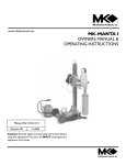
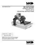
www.mkdiamond.com
Revision 202
MK-MANTA III
OWNER’S MANUAL
PARTS LIST &
OPERATING INSTRUCTIONS
08.2012
Manual Part# 161117
Caution: Read all safety and operating instructions
before using this equipment. This parts list MUST
accompany the equipment at all times.
INTRODUCTION
Congratulations on your purchase of a MK-Manta III Core Drill. We are certain that you will
be pleased with your purchase. MK Diamond takes pride in producing the finest construction
power tools and diamond blades in the industry.
Operated correctly, your MK-Manta III Core Drill should provide you with years of service. In order to help you, we have included this manual. This owners manual contains information necessary to operate and maintain your MK-Manta III Core Drill safely and correctly. Please take the
time to familiarize yourself with the MK-Manta III Core Drill by reading and reviewing this manual
before operating it.
Read and follow all safety, operating and maintenance instructions.
If you should have questions concerning your MK-Manta III Core Drill, please feel free to call our
friendly customer service department at: (800) 421-5830.
Regards,
MK Diamond
NOTE THIS INFORMATION FOR FUTURE USE:
MODEL NUMBER:
SERIAL NUMBER:
PURCHASE PLACE:
PURCHASE DATE:
NOTE: For your (1) one year warranty to be effective, complete the warranty card
(including the Serial Number) and mail it in as soon as possible.
2
TABLE OF CONTENTS
SAFETY
Safety Messages
Damage Prevention Message
General Safety Precautions
Hazard Symbols
California Proposition 65 Message
Safety Label Locations
Product Features
4
4
4-5
5
6
7
8
UNPACKING, CONTENTS and ASSEMBLY
Unpacking
Contents
Assembly
9
9
9
OPERATION
Operation
10-15
MAINTENANCE, ACCESSORIES, & TROUBLESHOOTING
Maintenance
Cleanup
Troubleshooting
Accessories
16
16
17-18
19
EXPLODED VIEW AND PARTS LIST
Exploded View & Parts List
20-29
ORDERING and RETURN INSTRUCTIONS
Ordering Information
Return Material Policy
Packaging Instructions
Authorized Service Centers
30
30
30
30
CONTACT and LIMITED WARRANTY
Contact Limited Warranty
31
31 3
MANTA CORE DRILL III
SAFETY
RULES FOR SAFE OPERATION
DANGER
Failure to follow instructions in this manual may lead to serious injury or even death! This equipment
is to be operated by trained and qualified personnel only! This equipment is for industrial use only.
The following guidelines should always be used when operating the core drill.
SAFETY MESSAGE / ALERT SYMBOLS
A safety message alerts you to potential hazards that could hurt you or others. Each safety message is
preceded by a safety alert symbol (
) and one of three words: DANGER, WARNING, or CAUTION.
DANGER
You WILL be KILLED or SERIOUSLY INJURED if you do not follow directions.
WARNING
You CAN be KILLED or SERIOUSLY INJURED if you do not follow directions.
CAUTION
You CAN be INJURED if you do not follow directions. It may also be used to alert against
unsafe practices.
Each message tells you what the hazard is, what can happen, and what you can do to avoid or
reduce injury. Other important messages are preceded by the word NOTICE.
NOTICE
You can cause PROPERTY DAMAGE to your machine if you don’t follow directions.
The safety labels should be periodically inspected and cleaned by the user to maintain good legibility
at a safe viewing distance. If the label is worn, damaged or illegible, it should be replaced. Contact
MK Diamond or your dealer for replacement.
CAUTION
Always keep alert. Do not allow familiarity (gained from frequent use) to cause a careless mistake. Always
remember that a careless fraction of a second is sufficient to inflict serious injury.
GENERAL SAFETY
• DO NOT operate or service this equipment before reading this entire manual.
Read and understand all warnings, instructions and controls on the machine.
• This equipment should not be operated by persons under 18 years of age.
• NEVER operate this equipment without proper protective clothing, shatterproof glasses, steel-toed boots and other protective devices required by the job.
4
MANTA CORE DRILL III
SAFETY
• NEVER operate this equipment when not feeling well due to fatigue, illness or taking medicine.
• NEVER operate this equipment under the influence of drugs or alcohol.
• Whenever necessary, replace nameplate, operation and safety decals when they become difficult
to read.
• ALWAYS check the machine for loose bolts and parts before starting.
• ALWAYS wear proper respiratory, head, ear and eye protection equipment when operating this machine.
•
Use the right tool. Do not use a tool or attachment to do a job for which it is not recommended.
Do not alter the tool. Maintain all tools with care for the safest and best performance.
• ALWAYS store equipment properly when it is not being used. Equipment should be stored in a clean, dry location out of the reach of children.
• ALWAYS insure that the switch is off before plugging unit into electrical power.
• NEVER leave the drill running unattended. Turn power off.
• DO NOT over reach, maintain control. Keep proper footing and balance at all times. Maintain a firm grip.
•
Should any part of this drill become missing or damaged, or any component fail to perform
properly, shut off the drill and unplug the power source. Replace the missing, damaged, and/ or
failed part before resuming operations.
ELECTRICAL SHOCK
NEVER touch electrical wires or components while the engine is running. They can be
sources of electrical shock which could cause severe injury or burns.
on
ACCIDENTAL STARTS
Before starting the equipment, be sure the ON/OFF switch is in the “OFF” position to prevent accidental starting. Place the ON/OFF switch in the OFF position before performing
any service operation.
ROTATING PARTS
Keep hands, feet, hair, and clothing away from all moving parts to prevent injury. Never
operate the motor with covers, shrouds, or guards removed.
5
MANTA CORE DRILL III
SAFETY
SILICA DUST WARNING
Grinding/cutting/drilling of masonry, concrete, metal and other materials with silica in their composition
may give off dust or mists containing crystalline silica. Silica is a basic component of sand, quartz,
brick clay, granite and numerous other minerals and rocks. Repeated and/or substantial inhalation of
airborne crystalline silica can cause serious or fatal respiratory diseases, including silicosis. In addition, California and some other authorities have listed respirable crystalline silica as a substance
known to cause cancer. When cutting such materials, always follow respiratory precautions.
Use appropriate NIOSH-approved respiratory protection where dust hazard may occur. Paper masks
or surgical masks without a NIOSH approval number are not recommended because they do little to
protect the worker. For more information about respirator programs, including what respirators have
received NIOSH approval as safe and effective, please visit the NIOSH website at:
http://www.cdc.gov/niosh/topics/respirators
Observe OSHA regulations for respirator use (29 C.F.R.§1910.134 and §1503.1).
Visit http://www.osha.gov for more information.
CALIFORNIA PROPOSITION 65 MESSAGE
Some dust created by power sanding, sawing, grinding, drilling, and other construction activities contain chemicals known (to the State of California) to cause cancer, birth defects or other reproductive
harm. Some examples of these chemicals are:
• Lead, from lead-based paints
• Crystalline silica, from bricks and cement and other masonry products
• Arsenic and chromium, from chemically treated lumber
For further information, consult the following sources:
http://www.osha.gov/dsg/topics/silicacrystalline/index.html
http://www.cdc.gov/niosh/docs/96-112/
http://oehha.ca.gov/prop65/law/P65law72003.html
http://www.dir.ca.gov/Title8/sub4.html
Your risk from these exposures varies depending on how often you do this type of work. To reduce
your exposure to these chemicals, work in a well-ventilated area, and work with approved safety
equipment, such as dust masks that are specially designed to filter out microscopic particles.
6
MANTA CORE DRILL III
SAFETY
SAFETY LABEL LOCATIONS
Safety labels contain important safety information. Please read the information contained on each
safety label. These labels are considered a permanent part of your saw. If a label comes off or
becomes hard to read, contact MK Diamond or your dealer for a replacement.
! WARNING
Label A
Grinding/cutting/drilling of masonry, concrete, metal and other materials with silica in
their composition may give off dust or mists containing crystalline silica. Silica is a basic
component of sand, quartz, brick clay, granite and numerous other minerals and rocks.
Repeated and/or substantial inhalation of airborne crystalline silica can cause serious
or fatal respiratory diseases, including silicosis. In addition,California and some other
authorities have listed respirable crystalline silica as a substance known to cause cancer.
FOR INFORMATION ON
SERVICE OR
WARRANTY
PLEASE CALL
1-800-474-5594
Label B
! WARNING
For Your Own Safety Read Instruction Manual
Before Operating Saw.
Wear Eye Protection.
Disconnect Saw Before Servicing, when Changing
Cutting Wheels and Cleaning.
Use Tool Only with Smooth Edge Cutting Wheels
Free of Openings and Grooves.
Replace Damaged Cutting Wheel Before Operating.
Do Not Fill Water Bath Above Water Fill Line.
See Manual for Pump Replacement.
Label C
B&C
A
Decal/Label
A
B
C
Location
Base - Top
Vacuum - Top
Vacuum - Top
Description
Warning Silica
Service or Warranty
Read Manual
7
MANTA CORE DRILL III
FEATURES
MK-Manta III Core Drill
The MK-Manta III Core Drill is a powerful all-purpose drilling rig that is designed to drill holes, up to 12
inches in diameter (14 inches with the 2 inch spacer), in all types of concrete slabs, floors, walls, and
ceilings. The MK-Manta III Core Drill is designed for easy anchoring using masonry anchors. A vacuum
pump is provided to facilitate quick and easy anchoring to smooth floor surfaces.
Motor
The MK-Manta III Core Drill is designed for use with a variety of motors. All motors are powerful two or
three speed units that provide the correct cutting speed over a range of diamond drill sizes.
CARRIAGE, COLUMN AND BASE
The carriage, column and base assembly of the MK-Manta III Core Drill is the strong, sturdy drilling
platform that provides the rigidity needed to quickly drill accurately placed, straight, smooth holes in
all types of concrete. The MK-Manta III’s base is slotted to provide easy anchoring of the drill, in a
variety of drilling situations, with a single masonry anchor. The slot also allows more than one hole
to be drilled from a single anchor location. The base contains four leveling screws to insure accurate
hole alignment even on uneven concrete surfaces. The carriage also has a handle and the base has
6” wheels to provide easy transport. The carriage travel is controlled by a strong rack and pinion gearsystem, that can be locked at any point on the column. The single spoked sliding handle allows that
operator to easily control the drilling pressure and speed. At the top of the column is a strong jackscrew that allows for additional bracing to overhead or opposite surfaces.
VACUUM PUMP
The vacuum pump provides quick and reliable mounting to smooth concrete slab and floor surfaces.
The powerful vacuum pump provides 25 PSI of holding power which equates to over 1800 pounds of
force, holding the MK-Manta III Core Drill securely, for safe, accurate drilling. The pump has a quick
disconnect connector on the hose at the base.
WATER SYSTEM
The water system for the MK-Manta III Core Drill is a simple hose hook-up and shut-off valve that provides water under pressure to the diamond drill bit. The water travels to the center of the bit through
the water swivel and spindle to insure that water is supplied to the cutting end of the bit, even is deep
drilling operations.
General Specifications
Motor 120V
Bit Capacity 1/2” to 14” (16” with motor spacer)
Bit Feed 27"
Motor Spindle 1 - 1/4” - 7
Column 2 -1/2” x 2 - 1/2” adjustable rack and pinion
Weight-combo Base 109 lbs. (including pump)
Weight-Combo Tilt Base 114 lbs (including pump)
Weight-Anchor tilt Base 95 lbs.
Size L x W x H 19” x 24” x 46”
L x W x H (mm) 480 x 610 x 1170
8
MANTA CORE DRILL III
CONTENTS
UNPACKING
Open the accessory pack and check each item with the contents list, making certain that all items are
accounted for and in good condition before discarding any packing material. If there are any missing
or damaged parts, call our toll free number 1-800-421-5830 for instructions before proceeding with
the assembly.
Contents of the carton: It varies depending on model. MK-Manta III Core Drill (including column, carriage, base and motor), Vacuum Pump and Accessory Pack.
Contents of the Accessory Pack: Control box, meter box knob, leveling screw (4), feed handle (1) and
knobs (2), water valve, vacuum base gasket, wrench, MK-Manta III manual, MK Diamond warranty
card, motor manual and motor warranty card.
www.mkdiamond.com
Revision 202
MK-MANTA III
OWNER’S MANUAL
PARTS LIST &
OPERATING INSTRUCTIONS
08.2012
Manual Part# 161117
Caution: Read all safety and operating instructions
before using this equipment. This parts list MUST
accompany the equipment at all times.
Owners
Manual
MK-Manta III
Vacuum Pump
(Combination
Models Only)
Accessory Pack
Control Box
MK DiaMonD Warranty CarD
Name
address
City
state
zip Code
phoNe
Fax
e-mail
produCt model
part NumBer
maChiNe serial#
where did you purChase this saw From? Name
q tile distriButor
q tool supply
date purChased
q home CeNter
q equipmeNt supply house
q Bldg material supply
are you a do-it-yourselFer q
or CoNtraCtor q
IF so, what type? tile q
q reNtal equipmeNt house
masoNry q
other
what Criteria was importaNt iN ChoosiNg this saw? (rate From 1 to 5, 5 BeiNg the most importaNt)
priCe
power
preCisioN
portaBility
availaBility
other
CommeNts or suggestioNs:
mK diamoNd warraNty 1315 Storm Parkway, Torrance, CA 90509 USA | www.mkdiamond.com | 1.800.421.5830 | 1.310.539.5158
If within one (1) Year from the date of purchase, this MK Diamond saw fails due to defect in material or workmanship, MK will repair it, free of charge when the unit is returned to the dealer where it was purchased. This warranty DOES NOT cover normal wear or damage resulting from operator abuse. In no event shall MK Diamond Products,
Inc. be liable for consequential damages arising out of the failure of any product if operated improperly. MK Diamond Products may act as a warranty station for motor/engine repairs based on an individual agreement with the manufacturer. This warranty is in lieu of all other warranties express or implied.
©2010 All Rights reserved. MK Diamond Products, Inc. • P/N 155037 MK Warranty Card (02/10)
Warranty
Card
ASSEMBLY
Feed Handle and Meter Box
WARNING
For your own safety and protection, do not attempt to operate this drill until it is
completely assembled and installed according to these instructions, and until
you understand the machines capabilities and the potential hazards associated
with it.
Step 1: Slide carriage assembly onto column. Assemble handle and hub.
Vacuum Gasket
Turn the vacuum base over. Press the gasket into the groove in the underside of the base. The gasket is cut at the factory to the correct length so that the two ends will butt together once the gasket is
installed.
Step 2: Assemble the two pieces of the water valve, and install the valve into the water swivel on the
motor, just above the spindle (see Milwaukee literature).
9
MANTA CORE DRILL III
operation
Final Assembly
Plug the cord from the motor into the upper outlet on the meter box (the one opposite the motor on-off
switch). The other outlet on the meter box is for use with the vacuum pump.
Drilling operations
Electrical Requirements
The MK-Manta III Core Drill rig has been equipped with a Milwaukee motor. The drill should be used
on an electrical circuit, separate from other loads, and protected by a 30 amp circuit breaker. the MKManta III Core Drill has been provided with a 20 Amp plug (NEMA 15-20) or a 30 Amp (Nema 15-30)
locking plug depending on the model.
Grounding
The MK-Manta III Core Drill is marked “Grounding Required” and has a three wire cord and three
prong grounding plug. The plug must be connected to a properly grounded outlet (see figure below).
If the tool should electrically malfunction or break down, grounding provides a low resistance path to
carry electricity away from the user, reducing the risk of electrical shock.
The grounding prong in the plug is connected through the green wire inside the cord to the grounding
system in the tool. The green wire in the cord must be the only wire connected to the toll’s grounding
systems and must never be attached to an electrically live terminal.
Your tool must be plugged into an appropriate outlet, properly installed and grounded in accordance
with all codes and ordinances.
WARNING
Improperly connecting the grounding wire can result in the risk of electric shock. Check with a qualified electrician if you are in doubt as to
whether the outlet is properly grounded. Do not modify the plug provided with the tool. Never remove the grounding prong from the plug.
Extension Cords
Do not use the tool if the cord or plug is damaged. IF damaged, have it repaired by an authorized
service facility before use. If the plug will not fit the outlet, have a proper outlet installed by a qualified
electrician. The use of a circuit protected by a ground fault interrupter (GFCI) is highly recommended.
Use extension cords of the proper cable size, referring to the following chart.
EXTENSION CORD MINIMUM GAGE FOR LENGTH
TOTAL LENGTH OF CORD IN FEET
Cord Length
25 ft. AWG
50 ft. AWG
75 ft. AWG
Wire Size (AWG)
#10
#8
#6
10
MANTA CORE DRILL III
operation
WARNING
Never use a extension cord smaller than shown in the chart. Be sure your extension cord is properly wired and in good electrical condition. Always replace
a damaged extension cord or have it repaired by a qualified electrician before
using it. Protect your extension cords from sharp objects, excessive heat and
damp or wet areas.
NOTICE:
Using an extension cord with inadequately sized wire causes drop in voltage,
resulting in loss of power and possible tool damage.
securing the rig: recommended methods
A. Use a concrete anchor. Use either a 1/2 or 5/8 concrete anchor to secure the base to the
work surface. Always be sure to level the rig and tighten the lock nuts on the leveling screws before
tightening the anchor. Using a concrete anchor, insert a bolt through the slot located on the base and
tighten the bolt firmly in the anchor.
WARNING
It is essential to always secure the rig to the work surface to help prevent
personal injury and also to protect the rig. An unsecured rig could rotate during
drilling and possibly cause injury. It could also cause the bit to chatter against
the work surface or bind in a hole, which can fracture the diamond. Always test
the anchor for firm attachment before drilling.
B. vacuum base. The MK-Manta III Comb Core Drill Rig is equipped with a vacuum pump. This
pump is designed to provide approximately 1800 pounds of total holding power. In order to provide
the most rigidity to your core rig the unit should be used on a relatively smooth surface such as concrete. If the surface is too porous or rough the vacuum mount may not hold securely.
1. Turn the vacuum pump on and step on the vacuum base until a vacuum is created and the base adheres to the work surface.
2. Level the rig using the leveling bolts. Use a minimum amount of adjustment to the leveling bolts to avoid breaking the vacuum seal.
The vacuum gauge should read approximately 25 pounds per square inch (PSI) of pressure. If the
gauge reads 20 PSI less, check the work surface for conditions which may interfere with adequate
suction such as cracks, dirt or debris on a porous surface.
WARNING
Do not drill if the gauge reads less than 20 PSI. Do not use vacuum base on
cracked, uneven, porous or vertical surfaces.
C. ADDITIONAL SUPPORT. For added rigidity, you may use a telescoping extension assembly in
conjunction with a concrete anchor or vacuum base. To use a telescoping assembly, first level the
rig with the leveling screws. Secure the rig with an anchor or the vacuum base. Place the top flange
of the extension against a ceiling or wall and place the other end on the jack screw of the column.
The assembly is adjustable up to 14 feet. Specifications for the different motors are listed in the table
below.
11
MANTA CORE DRILL III
operation
DRILLING SPEEDS
Bit Capacity 1/2" to 14"
Spindle 1-1/4"-7
Bit Feed 27"
L x W x H (inches) 19" x 24" x 46"
L x W x H (mm) 480 x 610 x 1,170
Motor Milwaukee
4004
Milwaukee
4090
Milwaukee
4094
Milwaukee
4096
Milwaukee
4097-20
Volts / Amps 120V / 20A
120V / 15A
120V / 20A
120V / 20A
120V / 15A
Shear Pin
Shear Pin
Slip Clutch
Slip Clutch
375/750
450/900
450/950
500/1,000
1 HP
1 HP
1 HP
1 HP
Clutch Slip Clutch
Motor RPM 300/600
Horsepower 1 HP
Combination
Base Drill
Stand*
Weight 109 lbs.
109 lbs.
109 lbs.
109 lbs.
109 lbs.
Includes Vacuum
Part# 158639
158641
157449
157448
158640
Combination
Tilt Base Drill
Stand
Weight 114 lbs.
114 lbs.
114 lbs.
114 lbs.
114 lbs.
Part# 158647
158649
158644
158645
158648
Includes Vacuum
Anchor Tilt
Base Drill
Stand
Anchor Base
Drill Stand
Weight
–
95 lbs.
95 lbs.
95 lbs.
95 lbs.
Part#
–
158657
158652
158653
158656
Weight
–
74 lbs.
74 lbs.
74 lbs.
74 lbs.
Part#
–
167324
167325
167326
167327
The MK-Manta III Core Drill, with Milwaukee motor will operate in either a high or low gear speed.
This speed combined with applied pressure provides the cutting action for the core bit. Speed selection and pressure are determined by hardness of material, aggregate size and grade of diamond
core bit. Generally, harder material and larger aggregates require more speed and pressure. Use low
speed for large diameter bits and high speed for small diameter bits. Changing of the speeds is accomplished by using the speed shift lever built into the gear case.
NOTICE:
Change the gears only when the motor is off.
All building materials and work surfaces are composed of aggregates of various size. Aggregates are
materials such as gravel or crushed stone. The size of the grains and the hardness of the material
affects the speed of drilling. Most building materials contain some type of steel reinforcements. All
MK-Manta III bits are designed to cut through these types of reinforcing steel. However, bits should
never be used for drilling solid steel plates. Proper selection of the diamond core bit should be based
on material to be drilled and performance requirements.
12
MANTA CORE DRILL III
operation
DRILLING Pressure and the ammeter
Steady, even pressure assures accurate holes and longer bit life. Always maintain consistent pressure so that the bit is constantly cutting.
15
18
NOTICE:
20
Too much pressure will damage the bit and motor. Too little pressure will glaze over the
diamonds, reducing cutting efficiency and prematurely wearing the bit. The ammeter is
the gauge on the Control Box. It provides pressure feedback information during drilling, allowing the operator to help prevent motor overload and premature bit wear. The
green areas are the operating range, and the red area is the overload range. Generally,
the operator should keep the ammeter needle in the upper area of the operating range
for large diameter bits, and in the lower green area for small diameter bits. If the bit
contacts steel reinforcing rods, the needle on the ammeter may jump slightly showing
a heavier load. If this occurs, do not decrease pressure or you may damage the diamonds. The MK-Manta III Core Drill may be operated with the ammeter needle into the
red area for the short period of time that it takes to cut through a steel rod.
Water supply
An adequate supply of clean water is necessary for drilling. Connect the water supply hose to the
hose fitting on the output of the core drill motor. Take precautions that the water supply will not be
interrupted during the drilling operations.
NOTICE:
If a bit is run dry it can be ruined in a few seconds.
CARRIAGE RIGIDITY
It is essential that the carriage fits snugly on the column to prevent the motor or bit from wobbling during drilling. Through normal use the carriage may loosen from the column and begin to wobble. Before drilling, always make sure the carriage is rigid by trying to wiggle it with your hand. If the carriage
is secure it should not move. If it does move, tighten the adjustment. Tighten only enough to remove
the play. Do not over tighten.
SHEAR PIN AND CLUTCH PROTECTION
The MK-Manta III Core Drill uses either a shear pin or a friction clutch to protect the gear and motor
against overload. The shear pin drives the outer portion of the drive spindle. If the motor should overload the pin will shear. Extra shear pins are supplied or can be ordered from MK Diamond’s Customer
Service. Tighten only enough to remove the play, do not over tighten. Another model features a friction clutch rather than a shear pin to protect the motor and gears. If the motor overloads the clutch will
begin to slip and the bit will stop rotating. The clutch is factory-set and does not require adjustments.
However, under normal use, the clutch may start to slip at low torque. If this happens, refer to the motors Owner’s Manual.
13
MANTA CORE DRILL III
operation
mounting bits
Bits with permanently attached adapters simply screw directly onto the threads of the drill spindle.
Ensure that the end of the bit butts up squarely against the shoulder on the spindle.
• Thread anti-clockwise to attach core bit.
• Thread clockwise to loosen.
WARNING
The MK-Manta III Core Drill, equipped with either the Millwaukee motor, has
a 1 -1/4” - 7 thread. For bits with other threads, use a shaft coupling. After a
bit has been mounted, turn the power on and check that there is a minimum
of run-out or wobble.
WARNING
To reduce the risk of injury, always unplug tool before attaching or removing
accessories. Only use specifically recommended accessories. Others may
be hazardous.
drilling procedure
When drilling through concrete floors, the core will generally drop from the diamond bit. Caution
should be provided for people and property below the drilling area.
1. Ensure that you have read and fully understand the complete operation of the Manta III Core Drill you have purchased prior to commencing drilling operations.
2. Select and install a diamond core bit appropriate for the job.
NOTE:
Grease the bit threads to help prevent the bit from seizing on the spindle due
to surface corrosion.
3. Select either high or low gear speed according to the chart in the Drilling Speeds section of this manual. (Do not shift speed when motor is on.)
4. Connect water hose to water swivel.
5. Secure the rig as described in the Securing the Rig section of this manual.
WARNING
If using the vacuum base, do not continue operations unless the vacuum
gauge reads more than 20 PSI. Normally, the gauge will read 23 inches or
more.
6. Turn the motor switch on the control box on. Turn the water on so that an adequate flow of water is supplied through the water swivel to the bit. Hold the sliding handle and slightly loosen the carriage lock knob. Slowly rotate the handle to lower the bit into the work piece - apply steady even pressure.
NOTE:
To prevent the bit from wandering, always use a light lead to start the hole
and wait for the diamond tip of the bit to penetrate the work surface before
increasing the load.
7. Use consistent pressure so that the bit cuts consistently, Insufficient pressure will cause the diamond core bit to glaze over. Too much pressure will overload the motor and crush the diamonds. Use the ammeter on the control box as a guide for proper pressure.
14
MANTA CORE DRILL III
CAUTION
operation
If the rig shifts during drilling, stop the motor, reposition the rig, and resume
drilling.
8. Monitor the water flow. If the water flow is adequate, the water leaving the cut should be slightly sludgy. When cutting metal rebar, the water should have a gray metal coloring.
Notice:
When drilling into prestressed concrete the bit may cut into the hardened
steel cable under tension. As the bit cuts through each strand, the tension in
the cable is released. The diamond segments on the bit crown can be damaged by the loose wires. The best prevention for bit damage is to use a core
bit designed especially for drilling in prestressed concrete.
9. When the cut is complete, keep the drill motor on and rotate the sliding handle to bring the bit up out of the hole. The bit may become stuck if the motor is turned off before the bit is completely clear of the hole. Once the bit is clear of the hole, tighten the carriage lock knob, turn off the motor and the water supply.
Note:
CAUTION
Normally the core will drop out of the bit, and remain in the hole. However,
in cases where the core sticks in the bit, it is sometimes necessary to push
the core up and down with the water running to allow the core to drop out.
Sometimes very light tapping on the barrel of the bit with a piece of wood will
loosen the core.
Perform the above action only with the motor turned off and the unit unplugged to prevent accidental starting and injury. Exercise extreme caution in
hand placement when removing a stuck core, as the core can be heavy and
inflict injury.
Deep drilling
When drilling holes that are longer than the core bit, follow the steps below.
1. Begin drilling the hole as usual. When you have drilled to the length of the bit, retract the bit from the hole and turn off the motor and water as usual.
2. Break off the core by driving a chisel or slender wedge into the circular kerf. Remove the core using core tongs, bent music wire or anchor bolts.
3. After removing the core, insert the bit carefully into the hole, attach a bit extension to the bit and core drill rig, then continue drilling as usual.
15
MANTA CORE DRILL III
MAINTENANCE
maintenance
Periodic maintenance, including cleaning, lubrication and inspection for wear and damage are routine
servicing procedures. Following the procedures as outlined can prevent serious damage or malfunctioning of the machine, and aid in preserving the useful life of core drill bits.
on
CAUTION Before performing any maintenance to the MK-Manta III Core Drill,
always unplug the unit from the electrical power source. Ensure the
On-Off switch is in the Off position, after servicing, and before plugging
the unit back in.
cleaning
Clean the machine after use, being careful to remove dust and slurry from the motor, vents, carriage
and column. Keep tool handles clean, dry and free of oil and grease. Use only mild soap and a damp
cloth to clean this tool since certain agents and solvents are harmful to plastics and other insulated
parts.
WARNING Never use flammable or combustible solvents around tools.
VACUUM BASE GASKET
Through normal use, the rubber gasket on the underside of the vacuum base can become worn,
requiring replacement. Periodically check the gasket for wear. If replacement is required, clean the
groove in the base before installing a new gasket.
16
MANTA CORE DRILL III
TROUBLESHOOTING
TROUBLESHOOTING
Problem
What to do?
Indication
Cause
1. Check fluid return. Fluid not muddy.
Evidence of steel
cuttings.
2. Check motor
speed range.
3. Check wear
picture of bit face.
Low Penetration
Rate Under
Prevailing
Drilling Parameters.
Bit worn out
Diamond without
exposure. (flush
with bond matrix)
Face of bit
plugged with cuttings
Face of bit covered with steel.
Steel cuttings
stick to bit face.
Wear picture of
polished diamonds.
Deep grooves.
Heavy
Wear at
Steel Tube
Heavy Wear.
17
Drilling in steel
reinforcement.
Speed not correct for the bit
size used.
Insufficient bit
load.
Solution/
Recommendations
Adjust drilling parameters to
recommendations for reinforcement.
See recommended speeds.
Replace with new bit.
Increase bit load.
Rotated with high Reduce RPM, or resharpen bit.
RPM on reinforcement
Loose material at Break core, clean bottom of
bottom of hole.
hole or reduce RPM and drill
with increased bit load.
Not enough fluid Clean bit face by sharpening
pumped. Cutmethods such as drilling dry at
tings burnt to
low RPM in a concrete block
matrix. Diamonds 3/8” deep max. Increase water
flow rate.
prevented from
cutting.
Steel cuttings
Clean bit face by drilling in
stick to bit face.
abrasive concrete block. ReDiamonds preduce RPM.
vented from
cutting.
Bit load too low.
Increase bit load.
Bit speed too
high
Worn or open
guide ways on
cradle. Borehole
is getting undulated.
Protruding steel.
Spindle is offset.
Bit out of true.
Bit is deformed.
Poor cleaning of
abrasive cuttings.
Crown clearance
worn out.
Use lower speed; increase bit
load.
Adjust guidance on carriage.
Adjust guidance on carriage.
Nicks or dirt on mounting faces.
Replace bit.
Improve flushing.
Replace bit.
MANTA CORE DRILL III
TROUBLESHOOTING
Cause
Solution/
Recommendations
If Leaking can be tolerated, continue drilling with increased attention.
Step 1: Apply wrench and rotate bit
in both directions while bit is under
tension. If not successful:
TROUBLESHOOTING
Problem
What to do?
No return of
fluid
Bit Stuck
Check where fluid
is leaking.
1. Try to raise bit, Loose material
if possible.
(cut steel or aggregates) is block2. Stop rotation.
ing between core
and bit or between
borehole and bit.
1. Stop rotation.
2. Raise bit.
Shear Pin Fail
Indication
Step 2: Try to over drill a hole
slightly larger then the stuck bit.
Drill moved during drilling (poor
fastening)
Bit deviates, guide
ways on cradle
have too much
clearance.
No clearance between tube I.D. or
O.D. and crown I.D.
or O.D.
Disconnect bit and remove, break
core. Start over with improved fastening of machine.
Disconnect machine, adjust guidance.
Drill impacted
to stall at lower
speeds.
Use recommended speed for the
bit diameter used. Raise bit when
it begins to load down. Feed bit
slowly when chattering begins.
18
Replace bit.
MANTA CORE DRILL III
accessories
ITEM
NUMBER
1
www.MKDiamond.com
2
www.MKDiamond.com
3
www.MKDiamond.com
4
www.MKDiamond.com
5
304149
304150
6
159620
DESCRIPTION
Core Bits MK-Black- Supreme Grade for
Concrete & Asphalt
Excellent performance in applications associated with moderate to high steel reinforcement.
Available Diameters 1/2” - 16”
Core Bits MK-Orange- Premium Grade for
Concrete & Asphalt
MK-Orange is a premium bit designed for wet
drilling applications that include light to moderate steel reinforcement.
Available Diameters 1” - 16”
Core Bits MK-Yellow- Standard Grade for
Concrete & Asphalt
MK-Yellow is an excellent choice for all types
of general wet drilling.
Available Diameters 1” - 14”
Core Bit Extensions Multiple tube extensions
may be used extending the drilling depth in
increments of 12”.
Available Diameters 1 - 1/4” to 6 /14”
Shaft Extensions easily attach to the core bit
and allow for a deeper drilling capacity.
12” Length
5/8” - 11 Male / 5/8” 11 Female
1 - 1/4” - 7 Male / 1 - 1/4” - 7 Female
Motor Spacer kit for Manta IIII core drill rigs
with Milwaukee motors. Allows rigs to use 16”
bits.
19
ACCESSORIES
MANTA CORE DRILL III
20
EXPLODED VIEW
MANTA CORE DRILL III
21
EXPLODED VIEW
MANTA CORE DRILL III
22
EXPLODED VIEW
MANTA CORE DRILL III
23
EXPLODED VIEW
MANTA CORE DRILL III
24
EXPLODED VIEW
MANTA CORE DRILL III
25
EXPLODED VIEW
MANTA CORE DRILL III
Item
AE
AE1
AE2
AE3
AE4
AE5
AE6
AE7
AE8
AE9
AE10
AE11
AF
AF1
AF2
AF3
AF4
AF5
AF6
AF7
AF8
AF9
AF10
AF11
AF12
AF13
AF14
AF15
AG
AG1
AG2
AG3
AG4
AG5
AG6
AG7
AG8
AG9
AG10
AG11
B
B1
B2
B3
B4
B5
B6
B7
B8
BA
BA1
BA2
Description
Assembly, M3 Base, Combination
Base, M3 Combination
Screw, ½-13 x 3 ½ Hex Hd. Cap, Full Thread
Level, Circular Bubble
Gasket, Neoprene size 1” x ½ x 47.8”
Plate, Air Seal
Gasket, 1/8” Neoprene Rubber
Fitting, ¼ MNPT x 3/8 Barb
Screw, Spade Hd. Thumb ¼-20 x ¾ w/ Shoulder
Label, Manta Serial Tag
Label, Caution, Safety
Label, MK, Adhesive
Assembly, M3 Base, Combination Tilt
Base, M3 Combination Tilt
Screw, ½-13 x 3 ½ Hex Hd. Cap, Full Thread
Level, Circular Bubble
Gasket, Neoprene size 1” x ½ x 47.8”
Plate, Air Seal
Gasket, 1/8” Neoprene Rubber
Fitting, ¼ MNPT x 3/8 Barb
Screw, Spade Hd. Thumb ¼-20 x ¾ w/ Shoulder
Label, Manta Serial Tag
Label, Caution, Safety
Label, MK, Adhesive
Screw, ½-13 x 4-½ Hex Hd. Cap
Washer, ½ SAE Flat
Washer, ½ Split Lock
Nut ½-13 Hex
Assembly, M3 Base, Anchor Tilt
Base, M3 Anchor, Tilt
Screw, ½-13 x 3 ½ Hex Hd. Cap, Full Thread
Nut, ½-13 Hex Hd.
Screw, ½-13 x 4 ½ Hex Hd. Cap
Washer, ½ SAE Flat
Washer, ½ Split Lock
Label, Caution, Safety
Level, Circular Bubble
Label, Manta Serial Tag
Label, MK, Adhesive
Label, For Information on Service
Assembly, M3 Wheel Bracket, Combo
Bracket, Wheel, Combo
Wheel 6” x 1 ½ x ½ axle
Cap, Push ½” Stainless Steel
Collar, ½ I.D. x 1” O.D. x 7/16
Screw, ¼-20 x ¾ Flat Head Socket
Knob, Knurled Head ¼-20 x 2 ½
Pad, Toggle ¼-20
Label, Manta 1-1/4 x 5 1/8
Assembly, M3 Wheel Bracket, Tilt Combo
Bracket, Wheel, M3 Tilt Combo
Wheel 6” x 1 ½ x ½ axle
26
PARTS LIST
Qty
1
1
4
1
3.98’
1
1
1
2
1
1
1
1
1
4
1
3.98’
1
1
1
2
1
1
1
1
2
1
1
1
1
4
2
2
4
2
1
1
1
1
1
1
2
2
2
4
1
1
1
1
2
Part #
n/a
157427
158284
157429
154543
157430
157431
154659
157432
157730
155576
157914
n/a
158393
158284
157429
154543
157430
157431
154659
157432
157730
155576
157914
158397
150924
153524
151282
n/a
157413
158284
151282
158397
150924
153524
155576
157429
157730
157914
155038
n/a
158392
157434
157435
157518
154657
157436
157437
155388
n/a
158321
157434
MANTA CORE DRILL III
Item
Description
BA3
BA4
BA5
BA6
BA7
C
C1
C2
C3
C4
C5
C6
C7
C8
C9
D
D1
D2
D3
D4
D5
D6
D7
D8
D9
D10
D11
D12
D13
D14
D15
D16
D17
E
E1
E2
E3
E4
E5
E6
E7
E8
E9
E10
E11
E12
E13
E14
E15
E17
EB
EB1
Cap, Push ½” Stainless Steel
Collar, ½ I.D. x 1” O.D. x 7/16
Screw, ¼-20 x ¾ Flat Head Socket
Knob, Knurled Head ¼-20 x 2 ½
Pad, Toggle ¼-20
Assembly, Telescoping Support
Tube, Telescoping Support
Rod, Telescoping Support
Clovis Pin ∅1/4 x 1 ¼
Clovis Pin ∅1/4 x 1 5/8
Pin, Cotter 1/16 x 5/8
Knob, Tri Plastic, 5/16-18 x ¾
Bracket, Telescoping Rod Support
Nut, M22 x 1.5
Washer, M22 Flat
Assembly, Carriage 2 ½”
Body, Carriage
Shaft, Gear, Short
Bearing
Plate, Adjustment
Slide, Carriage
Screw, 6-32 x 1/2 Flat Head Phillips Machine
Screw, 6-32 x 3/8 Flat Head Phillips Machine
Nut, 6-32 Nylok Hex
Knob, Davies ¼-20 x ¾
Washer, ¼ SAE Flat
Back, Carriage
Screw, 1/4-20 X 1 Socket Head Cap
Screw, ¼-20 x 5/16 Socket Head Set
Handle, Carriage
Screw, 1/4-20 X ¾ Pan Head Phillips
Label, MK USA
Screw, 1/4-20 X 1 ¼ Socket Head Cap
Assembly, Control Box, Fixed, Dual Switch 120V
Box, Fixed Dual Switch Control
Cover, Fixed Dual Switch Control Box
Screw, ¼-20 x ¾ Socket Head Cap
Washer, ¼ Split Lock
Screw, 10-24 x 5/8 Self Tapping
Ammeter 120V
Switch, 30A Toggle
Receptacle, Flanged 15A / 125V
Cord, Power SOWA 12/3 Yellow
Connector, Cord ½
Receptacle, Flanged Twist-lock 20A / 125V
Transformer, Current 120 V AC
Screw, 6-32 x ½ Pan Head
Plug, Twist-lock, 125V / 20A
Wire Harness (not shown)
Cover, Toggle Switch
Assembly, Control Box, Single Switch 120V
Box, Single Switch Control
27
PARTS LIST
Qty
Part #
2
2
4
1
1
157435
157518
154657
157436
157437
n/a
158340
158341
158452
158453
158451
158456
158342
158455
158454
n/a
155757
158348
137711
157317
157318
154448
157521
157519
151681
151915
157438
151049
154226
157440
157523
154334
159336
158428
158274
158276
152587
152591
153681
154489
154491
154473
154494
151307
157375
154490
153459
154556
154715
154301
158430
158385
1
1
1
1
2
1
1
1
1
1
1
1
2
3
8
8
8
8
1
1
1
4
6
1
2
2
4
1
1
1
2
2
6
1
2
1
3’
1
1
1
2
1
1
2
1
1
MANTA CORE DRILL III
Item
Description
EB2
EB3
EB4
EB5
EB6
EB7
EB8
EB9
EB10
EB11
EB12
EB13
EB14
EB16
F1
F1
F3
F4
F5
F6
F7
F8
G
G1
G2
G3
G4
G5
G6
G7
G8
G9
G10
G11
G12
G13
GB
GB1
GB2
GB3
GB4
GB5
GB6
GB7
GB8
GB9
GB10
GB11
GB12
GB13
GB14
Cover, Single Switch Control Box
Screw, ¼-20 x ¾ Socket Head Cap
Washer, ¼ Split Lock
Screw, 10-24 x 5/8 Self Tapping
Ammeter 120V
Switch, 30A Toggle
Cord, Power SOWA 12/3 Yellow
Connector, Cord ½
Receptacle, Flanged Twist-lock 20A / 125V
Plug, Twist-lock, 125V / 20A
Transformer, Current 120 V AC
Screw, 6-32 x ½ Pan Head
Wire Harness (not shown)
Cover, Toggle Switch
Assembly, Column
Manta, Core Drill Column (w/Gear Rack)
Screw, 10-32 X ½ Socket Hd. Cap
Washer, #10 Split Lock
Screw, M22 x 1.25 Jack
Screw, 1/2-13 X 3 ½ Hex Head Cap
Washer, 1/2 Split Lock
Washer, 1/2 SAE Flat
Assembly, M3 Vacuum Pump 120V
Pump, Vacuum 120V
Screw, 10-32 X ¾ Slotted Truss Head
Hose, 3/8 I.D., Air
Fitting, ¼ FNPT
Gauge, Vacuum
Nipple, ¼ NPT X Close Galvanized
Tee, 1/4 NPT Galvanized
Valve, ¼ NPT X Petcock
Filter, Water
Bracket, Pump Hold Down
Screw, ¼-20 x ½ Phil. Flat Head
Ferrel, Crimp
Fitting, 90° ¼ Street
Assembly, Vacuum Pump w/ Handle 120V
Pump, Vacuum 120v
Filter, Water
Gauge, Vacuum
Nipple, 1/4 MNPT X Close
Fitting, 1/4 FNPT X 1/4 FNPT X 1/4 FNPT Tee
Valve, 1/4” Pettcock
Hose, 3/8 I.D. Air
Coupler Body, 1/4 FNPT
Fitting, 1/4 MNPT X 3/8 BARB
Ferrell, Crimp
Base, Vacuum Pump
Handgrip, 3/4 X 4 9/16 Black
Screw, 10-32 X 1/2 Phillips Pan Head Cap
Foot, Rubber
28
PARTS LIST
Qty
Part #
1
2
2
6
1
1
3’
1
1
1
1
2
1
1
158387
152587
152591
153681
154489
154491
154494
151307
157375
154556
154490
153459
154715
154301
n/a
158425-2
157525
153684
157445
154574
153524
150924
158530
154475
157526
154656
154617
154477
152598
154497
154488
154476
157446
157527
154660
154615
154741
154475
154476
154477
152598
154497
154488
154656
154617
154659
154660
154495
139949
151052
154496
1
4
4
1
2
2
2
1
1
2
12”
1
1
4
2
1
1
1
2
2
1
1
1
1
1
3
2
1
6’
1
2
2
1
1
4
4
MANTA CORE DRILL III
Item
GB15
GB16
H
H1
H2
H3
H4
H5
K
K1
K2
K3
K4
LA
LA1
LB
LB1
LD
LD1
LE
LE1
LF
LF1
LJ
LJ1
M
M1
M2
M3
M4
MA
MA1
MA2
MA3
MA4
MB
MB1
MB2
MB3
MB4
N
N
N2
N3
Description
Screw, 1/4-20 X 3/4 Flat Head Phillips Cap
Nut, 1/4-20 Hex
Assembly, Handle, Slip
Hub, Slip Handle
Spoke, Slip Handle
Knob, Ball ½-20 Female
Screw, 1/4-20 X ¾ Thumb
Screw, ¼-20 X 1/4 Socket Head Set
Assembly, Accessory Pack (not shown)
Carton, Accessory Pack
Owner’s Manual, MK-Manta 3 Series Core Drill
Card, Warranty
MK Sell Sheet
Assembly, Motor, Milwaukee 4094
Motor, Milwaukee 4094, Shear Pin, 20A/120V
Assembly, Motor, Milwaukee 4096
Motor, Milwaukee 4096, Slip Clutch, 20A/120V
Assembly, Motor, Milwaukee 4004
Motor, Milwaukee 4004, Slip Clutch, 20A/120V
Assembly, Motor, Milwaukee 4097-20
Motor, Milwaukee 4097-20, Slip Clutch, 15A/120V
Assembly, Motor, Milwaukee 4090
Motor, Milwaukee 4090, Shear Pin, 15A/120V
Assembly, Motor, Eibenstock EBM 300/3 P
Motor, Eibenstock EBM 300/3/P, Slip Clutch, 20A/120V
Assembly, ¾” Motor Mount Plate, Hybrid, Milwaukee
Motor Mount Plate, Hybrid
Screw, 3/8-16 x 1 ¼, Socket Hd. Cap
Key, 3/8 x 3/8 x 5
Screw, ¼-20 x 1.0, Socket Hd. Cap
Assembly, ¾” Motor Mount Plate, Hybrid, CB748
Motor Mount Plate, Hybrid
Screw, 3/8-16 x 1 ¼, Socket Hd. Cap
Key, 3/8 x 3/8 x 5
Screw, ¼-28 x 1 ½ , Socket Hd. Cap
Assembly, ¾” Motor Mount Plate, Hybrid, Ebinstock
Motor Mount Plate, Hybrid
Screw, 3/8-16 x 1 ¼, Socket Hd. Cap
Key, 3/8 x 3/8 x 5
Screw, M8 x 1.25 x 25mm, Socket Hd. Cap
Assembly, 2”, Spacer Block Milwaukee (optional)
Spacer Block, 2” Milwaukee
Screw, 3/8-16 x 3 ¼, Socket Hd. Cap
Key, 3/8 x 3/8 x 5
29
PARTS LIST
Qty
4
4
1
1
1
2
1
2
1
1
1
1
1
1
1
1
1
1
1
1
1
1
1
1
1
1
1
4
1
4
1
1
4
1
4
1
1
4
1
4
1
1
4
1
Part #
154657
151893
n/a
157321
157322
154486
157432
157528
n/a
157323
161117
155859
155333
n/a
154633
n/a
155540
n/a
159263
n/a
159264
n/a
155976
n/a
158754
n/a
158412
157529
157520
151049
n/a
158412
157529
157520
154684
n/a
158412
157529
157520
157530
n/a
154721
161118
157520
MANTA CORE DRILL III
ORDERING, RETURN, & PACKAGING
ORDERING INFORMATION
You may order MK Diamond products through your local MK Diamond distributor or, you may order
direct from MK Diamond.
When ordering direct from MK Diamond, please have the following information ready before calling:
• The Model Number of the saw
• The Serial Number of the saw
• Where the saw was purchased and when
• The Part Number for the part(s) being ordered
• The Part Description for the part(s) being ordered
NOTE: There is a $25.00 minimum order when ordering direct from MK Diamond. A $5.00 charge will
be added to orders having a net billing value under $50.00. All purchases must be made using VISA,
MasterCard or American Express.
All parts may be ordered by calling toll free to – 800 421-5830 or 310 539-5221 and asking for
Customer Service. For technical questions, call – 800 474-5594.
RETURN MATERIALS POLICY
To expedite the service relative to the return of a product purchased through MK Diamond, please
observe the following:
NOTE: When returning all items, they must have been purchased within the previous twelve (12)
months.
• Have the Model Number of the saw
• Have the Serial Number of the saw
• Have the location of where the saw was purchased
• Have the date when the saw was purchased
• Contact Customer Service for approval to return the item(s)
• Obtain a Returned Goods Number (RGA) authorizing the return
• Follow the packaging instructions in the following section
• Ensure your item(s) are prepaid to the destination
For returned items, call toll free to – 800 421-5830 or 310 539-5221 and ask for Customer Service.
For technical questions, call – 800 474-5594 or 310 257-2845.
PACKAGING INSTRUCTIONS
•
•
•
•
•
Remove the motor and Support Assembly
Dry the drill before shipping
When packing, include the following: Core Drill, Vacuum Pump and Accessory Pack
Package the unit in its original container or one of comparable size (do not ship the unit partially exposed)
Ensure all parts are secured in the packaging to prevent moving
AUTHORIZED SERVICE CENTERS
For quicker repair time, you may contact MK Diamond Customer Service, toll free, at 800 421-5830
or 310 539-5221 for the Authorized Service Center closest too you or visit our web site at
www.mkdiamond.com. For technical questions, call – 800 474-5594.
30
MANTA CORE DRILL III
CONTACT & LIMITED WARRANTY
CONTACT
Please contact MK Diamond Products, Inc. Customer Service Department with any questions you
might have regarding distributors, parts or service.
Telephone: (800) 421-5830
Fax: (310) 539-5158
E-mail: [email protected]
Customer Service Hours: Monday through Friday, 6AM-4PM PST
MK Diamond Products, Inc.
1315 Storm Parkway
Torrance, CA 90501
MK DIAMOND PRODUCTS, INC. LIMITED WARRANTY
MK DIAMOND PRODUCTS, INC. will guarantee every machine they build, to be free from defects in
material and workmanship for (1) one year from date of purchase. The obligation of MK DIAMOND
PRODUCTS, INC. under this warranty is limited to the repair or replacement of any parts which,
under normal use, prove to be defective in material or workmanship. The parts involved or the unit
in question should be returned to MK DIAMOND PRODUCTS, INC. or to a point designated by us,
transportation prepaid.
This warranty does not obligate us to bear the cost of labor or transportation charges in connection
with replacement or repair of defective parts. Likewise, it shall NOT apply to any unit which has been
subjected to misuse, neglect or accident. This warranty does NOT apply to any machine which has
been repaired or altered outside our factory.
This warranty does NOT obligate MK DIAMOND PRODUCTS, INC., with respect to items not of our
manufacture, such as engines, motors, hydraulics, etc., which are subject to their own guarantees and
warranties.
We shall in no event be liable for consequential damages or contingent liabilities arising out of failure
of any equipment or parts to operate properly.
© COPYRIGHT 2012, MK DIAMOND PRODUCTS, INC. ALL RIGHTS RESERVED.
The MK Diamond logo is a registered trademark of MK Diamond Products, Inc. and may not be used,
reproduced, or altered without written permission. All other trademarks are the property of their respective owners and used with permission.
MK Diamond may have patents, patent applications, trade marks, copyrights of other intellectual
property right covering this product in this document.
This manual MUST accompany the equipment at all times. This manual is considered a permanent
part of the equipment and should remain with the unit if resold.
The information and specifications included in this publication were in effect at the time of approval for
printing.
31
MK-MANTA CORE DRILL III
OWNER'S MANUAL & OPERATING INSTRUCTIONS
MK Diamond Products, Inc.
1315 Storm Parkway
Torrance, CA 90501
Toll-Free: (800) 421-5830
Phone: (310) 539-5221
Fax: (310) 539-5158
www.mkdiamond.com