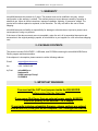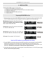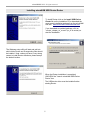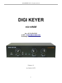
1
microHAM © 2006 All rights reserved DIGI KEYER microHAM fax. +421 2 4594 5100 e-mail : [email protected] homepage : www.microham.com Release 1.0 Joe Subich, W4TV 1 microHAM © 2006 All rights reserved TABLE OF CONTENTS CHAPTER PAGE 1. 2. 3. 4. WARRANTY .................................................................................................................................... 3 PACKACE CONTESTS ................................................................................................................... 3 IMPORTANT WARNINGS ............................................................................................................... 3 INSTALLATION ............................................................................................................................... 4 Preparing for Use........................................................................................................................ 4 Installing microHAM USB Device Router .................................................................................... 5 Installing the USB Driver.............................................................................................................. 6 Configuring the USB Codec ........................................................................................................ 7 Creating and Using Virtual Ports ................................................................................................ 9 5. PANEL DESCRIPTION ................................................................................................................. 10 Rear Panel ............................................................................................................................... 10 Front Panel ............................................................................................................................... 11 6. microHAM DEVICE ROUTER ....................................................................................................... 12 Menu: Router ............................................................................................................................ 12 Menu: Preset ............................................................................................................................ 13 Menu: Device ............................................................................................................................ 14 Menu: Virtual Port ..................................................................................................................... 15 Menu: Help ............................................................................................................................... 16 Device Configuration ................................................................................................................ 16 Ports: Control .......................................................................................................................... 17 Ports: FSK ................................................................................................................................ 17 Ports: 2nd FSK ........................................................................................................................... 18 Ports: CW ................................................................................................................................. 19 Ports: PTT ................................................................................................................................ 19 Ports: 2nd PTT ........................................................................................................................... 20 Ports: Squelch .......................................................................................................................... 20 Keying: Audio ........................................................................................................................... 21 Keying: PTT................................................................................................................................22 Keying: FSK from Keyboard ..................................................................................................... 22 FSK Messages .......................................................................................................................... 23 7. EXTERNAL KEYBOARD .............................................................................................................. 24 8. FUNCTIONN TEST ........................................................................................................................ 25 9. SPECIFICATIONS ......................................................................................................................... 26 Minimum Requirements ........................................................................................................... 26 Hardware Specifications .......................................................................................................... 27 10. FEATURES AND FUNCTIONS ................................................................................................... 28 APPENDIX A - DB15 RADIO CONNECTOR .................................................................................... 29 APPENDIX B – APPLE OS 10 INSTALLATION ............................................................................... 30 2 microHAM © 2006 All rights reserved 1 - WARRANTY microHAM warrants this product for 3 years. The product must not be modified in any way, except configuration or the warranty is voided. The warranty does not cover damage caused by improper or abnormal use, failure to follow instructions, improper installation, lightning, or excessive voltage. The product will be either repaired or replaced, at our discretion. The only cost will be the cost of return shipping. microHAM assumes no liability or responsibility for damage to other devices or injuries to persons as a consequence of using our products. If the terms of the above warranty are not acceptable, return the unit, all its associated documents and accessories in the original package, prepaid, to microHAM or to your supplier for a full refund less shipping cost. 2 - PACKAGE CONTENTS The product includes DIGI KEYER, USB cable, and CD-ROM containing the microHAM USB Device Router program and documentation. If the shipment is incomplete, please contact us at the following address: E-mail: [email protected] fax : +421 2 4594 5100 by Post: microHAM s.r.o. Nadrazna 36 90028 Ivanka pri Dunaji SLOVAKIA 3 - IMPORTANT WARNINGS You must set the CAT level jumpers inside the DIGI KEYER before using it for the first time. If you power Digi Keyer from an external power supply ALWAYS check the polarity of the external 13.8 V supply. If your radio includes uploadable firmware, always perform any upload from an RS-232 (COM) port on the computer - NOT through DIGI KEYER. 3 microHAM © 2006 All rights reserved 4 - INSTALLATION Installing DIGI KEYER consists of several steps: 1) preparing DIGI KEYER to work with your radio 2) installing microHAM USB Device Router (the control and interface software) 3) installing the USB drivers 4) configuring the Windows USB Audio Device 5) configuring Router Preparing DIGI KEYER for Use 1. Remove the top cover from the DIGI KEYER and set the CAT jumpers as shown in the following chart. The CAT interface jumpers must be configured to select the proper level for each radio type. RS-232 levels: Elecraft K2, JRC JST-245, Kenwood TS-480, 570, 870, 2000, Ten-Tec Argonaut, Jupiter, Omni V, Orion, Pegasus, Yaesu FT-847, 920, 1000MP, Mark V, Mark V Field, 2000, 9000 RS232 IF-232 levels: Kenwood TS-140, 440, 450, 680, 690, 711, 790, 811, 850, 940, 950 IF232 FIF-232 levels: Yaesu FT-100, 736, 747, 757GXII, 767, 817, 840, 857, 890, 897, 900, 980, 990, 1000, 1000D FIF232 CI-V levels: All Icom radios, Ten-Tec Omni VI CI-V Note: the CAT interface is not configured at the factory. 2. Plug the DB15M on the radio cable set into the DB15 connector on the rear panel of the DIGI KEYER and plug ALL connectors from the cable set to the appropriate jacks at the rear panel of your transceiver. Each connector on the radio interface cable is marked same as the matching jack on your transceiver. DO NOT turn on the radio or external power supply at this time. 3. If the radio cable ends with leads for external power, connect these leads to a 12-16V DC power supply. Be sure to observe the proper polarity. 4 microHAM © 2006 All rights reserved Installing microHAM USB Device Router To install Router click on the Install USB Device Router link on the installation CD or download the most recent installation package from the microHAM web site: www.microHAM.com/downloads.html. If you download an updated package, click on "urouter_release_xx_xx.exe" (xx_xx is version) to start the installation. The Windows setup utility will start and ask into which folder Router and its supporting files should be installed. Note: unless you have a very strong reason to install Router elsewhere, please accept the default location. When the Router installation is completed, UNCHECK the "Launch microHAM USB Device Router" box. The USB device driver must be installed before starting Router. 5 microHAM © 2006 All rights reserved Installing the USB DRIVER Connect the USB cable to the DIGI KEYER USB jack, plug the other end of the USB cable into an open USB port in your computer. The automatic Wizard will appear, insert the installation CD into the CDROM drive and select "No, not this time" when asked to connect to Windows Update. Then click "Next." Now, click Install from specific location and use the path to the Router installation directory. The default path is: C:\Program Files\microHAM\drivers\d2xx Wait until the driver is copied. During installation on Windows XP a driver certification dialog will appear. Ignore this message and click "Continue Anyway". If the USB driver is successfully installed, you should see a "microHAM USB Device" driver in Universal Serial Bus controllers section of Windows Device Manager without any exclamation mark. 6 microHAM © 2006 All rights reserved Configuring the USB Audio CODEC Windows will automatically install the USB Audio Device driver to support the USB Audio CODEC in DIGI KEYER. Windows automatically selects any newly installed Audio Device as the default device for Sound Playback and Sound recording. This is undesirable as Windows Sounds would be played through DIGI KEYER and onto the air! Open "Sounds and Audio Devices" in Control Panel and reset the Default device for Sound Playback and Sound Recording to your computer's primary sound device. 7 microHAM © 2006 All rights reserved Configuring the microHAM USB Device Router The MicroHAM USB Device Router (Router) program provides a Windows compatible configuration tool for microHAM USB Devices (DIGI KEYER as well as microKEYER, CW Keyer and USB Interfaces) and software interface to other Windows applications (loggers, digital mode software, etc.). The software interface is provided as Virtual Serial Ports. To configure and use DIGI KEYER with Windows based application programs it is necessary to have installed the USB driver, started the Router, and applied power to DIGI KEYER by turning on the attached radio or external power supply. Router is then configured to match the requirements of the application (logger or digital mode) software. DIGI KEYER Status When the USB driver is installed correctly and DIGI KEYER is powered from a radio or external 12V DC supply Router will show a device tab with a GREEN check beside the device name (DIGI KEYERI). When Router shows a YELLOW “X” insted of a green , it means the USB driver is correctly installed but DIGI KEYER is not receiving power from the radio or external supply. When Router shows a RED “X” insted of a green , it means the device is disconnected and Router does not see the USB part of DIGI KEYER. This happens when the USB cable is unplugged or the USB driver is not correctly installed. Initial Setup Router must be used to configure DIGI KEYER to function properly. The device configuration tab (in the red rectangle) is used to setup each part of the DIGI KEYER – virtual ports for communicating with the application (Ports), audio levels, PTT and keyboard FSK (keying), and stored FSK messages (FSK Messages). 8 microHAM © 2006 All rights reserved Creating and Using Virtual Serial Ports microHAM Router provides a set of virtual serial ports which allow Windows applications (loggers and digital software) to work with DIGI KEYER just as they would work with "real" (hardware) serial ports. In order to use these virtual Ports, you must first define the virtual ports and then assign each function (radio control, PTT, CW, FSK, etc.) to a virtual port. You may create and assign the ports manually, load the default template, or load an application specific template if one is availble for your particular program. To load the default template, select Device | Load Template and select "dk_default.tpl" from the available templates. The default template will create virtual ports at COM4, COM5, COM6, COM7 and assign radio control (CAT) to COM4, PTT for RTS on COM4, CW to DTR on COM5, and FSK to COM6. The default is compatible with many logging programs and digital mode packages. If you alredy have ports defined at COM4, COM5, COM6 or COM7 or want to define other virtual ports, you may do so by selecting Virtual Port | Create and selecting the ports you need for your particular set of applications. DO NOT define a port that is already in use (for example, COM1 or COM2 which are hardware ports on many motherboards) or a virtual port that is used by another USB device. Once you have defined your initial confirguration, you may want to save it both as the "Power Up settings" (Device | Store as Power up Settings) and as a Preset (Preset | Save As) in case you ever need to reset DIGI KEYER. 9 microHAM © 2006 All rights reserved 5 PANEL DESCRIPTION All connectors for connecting the computer, radio and accessories are located on the rear panel. Rear Panel (1) – PA PTT: PTT output for Power Amplifier Ground during transmit TIP - Signal SHELL - Ground (2) - LNA PTT: Control output for Low Noise Amplifier Ground during transmit TIP - Signal SHELL - Ground If the jumper is in SS position, open collector switching transistor is connected to the PAPTT or LNAPTT output jack. The transistor can switch up to 48V/1.5A. This position is appropriate for modern Power Amplifiers with electronic keying and LNA bypass relays . Check manual of your PA and LNA to be sure the power requirements do not exceed the transistor rating. If the requirements exceed 48V/1.5A set the appropriate jumper to the RE position. This position connects the relay contact to the output jack. Maximum rating for the relay is:125VAC/2A or 60VDC/2A. TIP: If you are not sure about keying voltage of your amp on LNA, use the RE position. (3) - RADIO: DB15F connector for radio interconnection – a detailed description is in Appendix A (4) - REM: MiniDIN6 for PS/2 keyboard or numeric keypad. (5) - USB: USB B connector for computer connection. Connect a standard USB A-B cable. 10 microHAM © 2006 All rights reserved Front Panel (1) – POWER YELLOW color indicates when unit is powered (2) – TX Adjusts transmit audio level (drive) (3) – CW/FSK RED color indicates when CW is active, GREEN indicates when FSK is active (4) – SQL GREEN color indicates when squelch is active (5) – PTT RED color indicates when PTT is active (6) – RX #2 Adjusts receive audio level from the second (sub-, aux-, etc.) receive channel. (7) – RX #1 Adjusts receive audio level from the main receive channel. 11 microHAM © 2006 All rights reserved 6. microHAM USB DEVICE ROUTER General Router settings can be invoked by clicking on Router main menu. ROUTER MENU Restore Router Settings: used to restore settings from a urs file created by the backup command. Restoring a backup will delete all current Router settings including presets, use it carefully! A urs file can be used only on the system which generated the file (the file contains the unit serial number) and a computer with same port assignments. Backup Router Settings: used to create backup urs file. This file contains Router settings for all Devices defined in Router including Presets. Options | General - Load Router on Start-up: when checked, Router will start automatically each time the computer is started or rebooted. Options | General - Start Router Minimized: when checked, Router will started minimized Options | Digital Band Map: Customizable band boundaries for the digital modes used for automatically selecting VOICE/DIGITAL settings. The Digital Bandmap has no effect on the DIGI KEYER. Minimize: Clicking this will minimize Router to the system tray at the bottom right corner of the Windows Taskbar (the "System Notification Area"). . TIP: When Router is minimized you can restore it by double-clicking on the Router tray icon. Exit: Clicking on this item will terminate Router. Note: when Router is terminated, application software will be unable to communicate with DIGI KEYER and the radio. 12 microHAM © 2006 All rights reserved PRESET MENU The requirements of each application (logging, control and digital mode programs) are different and each program handles radio control, CW / FSK/PTT keying, and the sound card its own way. In some instances what will work for one application may not work properly with another. To get maximum performance from DIGI KEYER, you may wish to customise the settings for each application. For easy switching among applications, Router supports up to 12 user definable Presets. Different DIGI KEYER configurations can be stored in these presets and recalled almost instantly simply by clicking on the preset button. Each preset contains the settings for all devices connected to, and controlled by Router. For example, if Router controls a DIGI KEYER, a microKEYER, a CW Keyer and a USB Interface, each preset remembers the settings for all four devices including the assignment of COM ports and the contents of all sub-tabs except contents of the FSK/CW Messages tab. There are three ways to apply a preset once it is created: 1. Click on Preset and select the desired preset from the pull-down menu. 2. Click on a preset button. To have buttons visible in Router, Preset | Show Buttons must be checked. When the settings from a preset are applied a green light located in the preset button is lit. This green light lit ONLY when all settings in Router are same as were stored in preset. If some parameter is changed, light is turned off, indicating that the current settings are not same as stored in the preset. 3. By right clicking on the system tray icon when the Router is minimized. All presets and the current router configuration are stored to the registry when Router is closed and recalled when Router is loaded. Save as - Saves the current Router settings to a preset for future use. Rename - Allows renaming of an existing preset. Delete - Delete chosen preset. Show buttons - When checked, Router shows the preset buttons. 13 microHAM © 2006 All rights reserved DEVICE MENU Router can control several devices. This allows configuring the settings for all connected devices at one time by using the Presets described in 6.2 Each device has its own tab (page) in the main Router notebook. The content of a device tab depends on device type. Adding a device is automatic the first time Router detects a supported device (USB driver). Once detected, a device remains in Router even though device is disconnected. Each device is identified by product identification number and a unique serial string. Rename – Creates a custom device name. This is useful if two or more devices are connected to the Router. For example CW KEYER, micro Keyer and USB Interface II can be renamed to more identifiable names as shown here.. Delete - Removes a device from the Router. Only disconnected devices with a RED “X” on device tab can be removed. To disconnect a device from Router, unplug the USB cable from the computer or device. Load Template – will automaticaly configuring Router from a template (*.tpl file). When clicked, Router will open a standard File Load dialog window and the desired template can be chosen. Router loads templates from the template directory – the default location is: C:\Program Files\microHAM\template. When Router loads a template, it looks for an html file with the same name as the template in the same directory. If such file is found, it is displayed. If Router fails to find an html file, it will look for a txt file with the same file name as template in same directory. If such file, is found it is displayed. Save Template - will save the current Router settings to template file. When clicked, Router will open a standard File Save dialog window. Router saves all templates to the template directory – the default location is: C:\Program Files\microHAM\template. A documentation file in plain text (txt) or hypertext (html) format can be created manually and attached to the template. The documentation file must have the same name as the template and must be located in the same directory. Templates are a powerful tool for quickly configuring Router to work with a particular application or for other purposes. Template files are interchangeable between different computers and transceivers and are well suited to clone setups when using the same application in multi-computer stations or for sharing custom setups between users. 14 microHAM © 2006 All rights reserved VIRTUAL PORT MENU It is necessary to create several virtual serial ports (COM ports) in order for a Windows application (logging, control or digital mode program) to access microHAM devices. By using templates, the neccessary virtual ports are created automatically. However, virtual ports can also be created manually. Create - Creates virtual COM ports. It is possible to select more ports at once by holding Ctrl key on keyboard and clicking on COM port numbers. Creating of virtual port may take a long time (several tens of seconds) on Windows 98/ME, be patient. Delete - Deletes any single virtual port. Delete All - Deletes all previously created virtual ports. Do not delete a virtual port unless all applications using that port have been closed. TIP: In order to avoid conflicts, do not use the number of COM ports that are already defined in Windows (hardware COM port or virtual COM port from another USB -> serial adapter). Successfully created Virtual Serial Ports can be reviewed in Device Manager, under the ELTIMA folder. Note: in Win98SE the ports are in the PORTS folder with two entries, the Virtual Serial Port and a "Null" copy.) Properly working ports should not display an exclamation mark (!). 15 microHAM © 2006 All rights reserved HELP MENU microHAM Home Page - Link to www.microHAM.com microHAM Downloads page - Link for downloading the current software and firmware updates Show Tooltips - When checked, small, single line help is displayed below the mouse cursor About - Shows the version number DEVICE CONFIGURATION TABS There are three (3) tabs for configuring DIGI KEYER. Each tab controls a part of DIGI KEYER's functions. Any change to the first two (2) tabs are applied immediately to DIGI KEYER. Changes in Messages are NOT applied automatically. To store them use buttons Store or Store All. Ports - used to assign virtual ports to the DIGI KEYER for use by applications. Keying - used to configure timing of the PTT signal, opertion of the FSK keyboard and the audio porcessor. Messages – used to configure stored FSK messages. Ports Tab Once the virtual ports have been created they must be associated with a specific device channel (e.g., Control, CW, PTT, etc.). These assignments should correspond to settings of the application software and must be configured first in Router then in the application (e.g., logging program, MMTTY, STREAM, etc.). Proper configuration of the COM ports assigments in this tab is most important for intergration with loggers. Read the following information carefully. DIGI KEYER has seven functions with indication of the state and settings applied by the host application – – – – – – – Radio Control (uses RxD and TxD) FSK (uses TxD and optionally RTS/DTR for PTT) 2nd FSK (uses TxD and optionally RTS/DTR for PTT) CW (uses DTR or RTS) PTT (uses DTR or RTS) 2nd PTT (uses DTR or RTS) Squelch (uses CTS, DCD, DSR or RING) General note: Do not assign virtual ports to the channels which are not used by the application. It is unnecessary and only consumes resources. 16 microHAM © 2006 All rights reserved CONTROL PORT The control channel is used by the host application to control transceiver frequency, mode, T/R switching and many other parameters. The application communicates with the radio using a serial protocol. Most modern radios implement some form of serial control but almost every radio implementation is different. The amount of radio control depends on the particular application and radio. TIP: The COM port number assigned in Router MUST match the port number assigned in the host application. First configure the virtual COM ports in Router then configure the application. When a COM port is assigned in the Router but not in the application (or no application is running) Router will show the channel as closed. When an application opens the COM port assigned for control (usually at start-up), Router shows the channel as open and displays baud rate, data bits, parity and number of stop bits used by the applicaiton. For example, 4800 8N2 means: 4800 baud, 8 bits data length, parity = none, and two stop bits. TIP: If the application permits, always configure the Radio Control port to use two stop bits. Communication is a little bit slower (9%) but more reliable. Some radios require two stop bits. Data flowing thru the Control channel are indicated by two arrows. A green arrow indicates data flow from the host application to the radio and a red arrow indicates data flow from the radio to the application. The virtual COM port assigned for Control can be shared with CW and/or PTT but sharing must be specifically supported by the application. Many applications do not know how to share the radio port with other functions, use the control lines (RTS, CTS, DTR, DTS) for handshaking, or apply a fixed level. FSK PORT The FSK channel is used by the application program to send FSK keying signal. FSK is used primarily for RTTY. It is very important to understand the difference between FSK and AFSK. FSK is a digital (On/Off) signal from the computer serial port (or external modem). This signal is used in the transceiver to generate a frequency shift. FSK must be supported by the transceiver (this mode is commonly labeled RTTY or FSK). AFSK is a analog signal generated by the computer sound card (or external modem) used in the transceiver modulation circuits for operating digital modes as RTTY, PSK31, AMTOR etc. Computer sound card generated AFSK or PSK does not require special transceiver support and can be used in the LSB, USB or FM mode of the transceiver. Some radios have dedicated modes for AFSK (generally labeled PKT or DATA) with special features. It is very important to properly adjust the audio drive level of an AFSK system so as to not overdrive the first transmit audio amplifier stage in the transceiver and produce a wide, distorted signal, full of intermodulation products. It is important to appreciate that distortion generated at this point due to overdrive CANNOT be reduced or eliminated by the reduction of the microphone gain control – it is the signal level that must be adjusted to be about the same as would be expected from a microphone. 17 microHAM © 2006 All rights reserved The microphone gain control then becomes a form of transmit power control. An initial indication of proper audio drive level can be seen on the ALC meter of the radio. Provided that there is NO audio processing in circuit and that the microphone gain control is in its normal operating position, then, if the ALC does not show or just starts to indicate during transmission, the signal is likely to be clean. It is also important is to turn off the microphone compressor, ANY transmit audio equalizer, AND transmit DSP when AFSK is used. DO NOT use any form of digital modulation (sometimes called "Transmit DSP") with AFSK or PSK. Some transceivers bypass these circuits automatically when signal is routed to the rear audio jack instead of the microphone jack, but some do not (for example, the TS-850). Edited by Geoff Anderson, G3NPA Whenever possible, if your transceiver supports FSK, use FSK for RTTY. It's a only sure way to get a clean RTTY signal no matter the gain setting and compressor (processor) setting on your radio. When a COM port is assigned to the FSK channel in Router but not in the application program (or no application is running), Router shows the channel as closed. When an application opens the COM port (usually at start-up), Router shows channel as open and displays the baud rate, data bits, parity and number of stop bits in use. For example, 45 5N1.5 means: 45 Baud, 5 data bits, parity = none, 1.5 stop bits. The virtual port used for FSK can optionally support PTT (required in basic MMTTY settings). Do not share the FSK port with any other function. TIP: If you see a baud rate other than 45 baud, the application is not configured correctly for normal RTTY operation. FSK data flowing thru the channel are indicated by green arrow. To test operation of FSK from the computer to the radio click on Test button with no port assigned or the port closed. More details about function checks are described in chapter 12.2 2nd FSK PORT The second FSK channel is identical to the primary FSK channel. The second FSK port is only usefull for radios with two receivers such as the FT-1000D, FT-1000MP, Mark V, Orion or IC-7800. Audio output from the second receiver is automatically connected to the right channel of the USB sound processor. The second instance of the RTTY program (for example MMTTY) should specify "right channel" for its audio source and should be configured to use the 2nd FSK port for its FSK output. 18 microHAM © 2006 All rights reserved CW Port By their very nature, USB ports are not well suited to transfer the real time events required for CW keying on virtual serial port control signals (DTR). In addition to the latency in USB, there are also latencies caused by computer CPU load, internal Windows message processing (inter-process communication) and data flow from another peripherals using the USB ports. This can result in transmitted characters being garbled. To minimize these unwanted operating system effects Router uses a specially developed oversampling and prediction algorythm to assure the smoothest possible transfer of control signal events over USB. Thanks to this principle, CW keying in the Router is in most cases usable up to 50 WPM if the application generates keying signals accurately and does not consume 100% of CPU time at the highest priority class. Router allows assigning a virtual serial port for the CW channel DTR or RTS output control line. TIP: More applications use DTR for CW than RTS. When a COM port is assigned in the Router but not in the application (or the application is not running), Router shows the channel as closed. When an application opens the COM port (usually at start-up), Router shows the channel as open. Activity and state of the CW channel is indicated by red arrow. If port is opened, it does not mean that it is properly configured for CW keying. The Red arrow will light in time with the transmitted CW characters when port is properly configured in the application. To test operation of CW from the computer to the radio click on Test button with no port assigned or the port closed. More details about function checks are described in chapter 12.2 PTT Port The PTT channel is used for T/R switching of the transceiver, Power Amplifier and Low Noise Preamplifier (LNA). An internal T/R sequencer assures 100% protection against transmitting through the LNA or hot switching of the PA when the PTT channel is used for T/R switching. More information about T/R switching, DIGI KEYER PTT outputs and the sequencer is provided in chapter 15.3 Router allows assigning a virtual serial port to the PTT channel and supports PTT via DTR or RTS. TIP: More applications use RTS for PTT than DTR. When a COM port is assigned in the Router but not in the application (or the application is not running), Router shows the channel as closed. When an application opens the COM port (usually at start-up), Router shows the channel as open. Activity and the state of PTT channel is indicated by arrow. If port is opened, it does not mean that is properly configured for PTT keying. The arrow will light during the entire transmission when port is properly configured. Operation of the PTT outputs is described in chapter 15.3 19 microHAM © 2006 All rights reserved TIP: Always use serial PTT instead of the radio command PTT or VOX. It is the only sure way to assure proper sequencing of an LNA and Power Amplifier. To test basic operation of the PTT from the computer to the radio, click on the Test button with no port addigned orthe port closed. More details about function check are described in chapter 12.2 2nd PTT Port The second PTT channel is identical to the primary PTT channel. Squelch Port Even though most current applications do not support readback of squelch and do not have the ability to perform specific functions based on its status, we have decided to include this feature in Router. Perhaps someday applications will be able to detect the squelch and use this information for configurable automated functions like audio recording. Router allows assigning a virtual serial port to squelch as CTS, DSR, DCD or RING.. When a COM port is assigned to the squelch channel in Router but not in the application (or no application is running), Router shows the channel as closed. When an application opens the COM port (usually at start-up), Router shows channel as open. When squelch is active, this state is indicated by a red arrow. 20 microHAM © 2006 All rights reserved KEYING TAB The Keying tab includes controls for the USB Audio processor, PTT and FSK Keyboard. USB Audio The sound card configuration depends on the capability of your application software. Some software can directly drive the sound mixer controls. Transmit Level: sets the level of the audio output from the digital to analog converter. Preset the slider to about 50 to 80% of full scale and adjust the drive to your transceiver with the TX pot on the front panel of DIGI KEYER. RX sub & RX main: these "stacked LED" displays that show the audio level into the analog to digital controller. Adjust the RX #2 and RX #1 pots on the front panel of DIGI KEYER so that the strongest signals only occasionally show RED. Sample Rate: sets the sample rate used to display the RX level displays. Because of the nature of the Windows sound system, it is best to set the sample rate to a multiple of the sample rate (or "clock rate") of your applications. For example, since MMTTY defaults to a 11025 clock, 44100 Hz sample rate is the best setting for MMTTY. Similarly since PSKcore used by many logging programs defaults to 48000 Hz sampling, a 48000 Hz sample rate in router will work best with PSKcore based programs. Generate Test Signal: causes DIGI KEYER to output a 1500 Hz audio tone for setting the transmit output level. Some tips from Geoff Anderson, G3NPA: TIP: If you have achieved the correct settings for the transmit levels, you will see that changing from the PSK tuning tone to typing text, will make the transmitter power swing from 50% (no typing) to 100% (typing or tuning-tone) as observed on an RMS or average reading meter. This change in power is correct. If you do NOT see this 50% change (or greater), then you are probably overdriving the radio. Please note that some radios have inbuilt power meters which give a PEAK reading and therefore the change in level discussed above will not be observed. TIP: Although it is a common belief to the contrary, it is in fact quite alright to let the transmitter ALC line operate on PSK31. The ALC line will control the drive level without clipping in the same way that it does on voice operation. TIP: Don't fall into the trap of thinking that because the transmit signal on the waterfall looks good that your actual signal is OK. All the waterfall is showing during transmit is the local audio and NOT the resultant transmitted signal. 21 microHAM © 2006 All rights reserved PTT – T/R KEYING DIGI KEYER has three (3) PTT outputs: PTT, PA PTT and LNA PTT. PTT is brought out to the DB15 Radio Port. PA PTT and LNA PTT are available on RCA connectors at the DIGI KEYER rear panel. PTT is normally wired to the radio Accessory jack and is used to switch the radio into transmit. PA PTT is present at the DIGI KEYER rear panel RCA jack and is designed for switching a power amplifier. PA PTT is enabled by checking the PA PTT box. PA PTT will close before transceiver PTT by the amount of selected PTT Delay and will open at the same time as the transceiver PTT. LNA PTT is present at the DIGI KEYER rear panel RCA jack and is designed for switching (bypassing) a low noise preamplifier (LNA) during transmit. LNA PTT is enabled by checking the LNA PTT box. LNA PTT will close before the transceiver PTT by the amount of selected PTT Delay and will open after the transceiver by the same amount. FSK from Keyboard If an external PS/2 keyboard is attached to the MK, Router supports additional settings for FSK. Diddle LETTERS will generate the "LETTERS" character if nothing is being typed UOS automatically generates the "Unshift on Space" function when checked Type ahead enables a type ahead buffer for the keyboard. QWERTZ layout configures DIGI KEYER for the alternate keyboard layout Invert FSK: Unlike AFSK, an FSK signal cannot be inverted by most application programs because the UART used in a real serial port lacks that capability. Because DIGI KEYER is a software defined interface, it can invert the FSK signal. When the Invert FSK box is checked, MK changes the “at rest” state of the front panel FSK light. FSK green led will light continuosly and go off when FSK signal is present. If your radio requires inverted FSK keying, your first choice should be to use the radio’s menu, not DIGI KEYER (check your operating manual for specific information). Invert FSK should be checked only for radios which do not provide this support. 22 microHAM © 2006 All rights reserved FSK MESSAGES TAB On this tab you can define nine messages of up to 50 characters each which are stored in DIGI KEYER's non-volitile memory. Each memory may have a programmable repeat delay and/or call another memory. Commands which may be included in a memory are: Set PTT: Clear PTT: CR & LF: close PTT. release PTT. Insert Carriage Return/Line Feed Jump to: Delay: used for looping a message or calling another message sets the delay in seconds before looping or calling another message Store: Store All: saves one message to DIGI KEYER memory saves all messages to DIGI KEYER memory Load from File: loads all messages from file Save to File: saves all messages to file Messages can also be saved and replayed also using an external keyboard attached to the Remote jack. 23 microHAM © 2006 All rights reserved 7 - EXTERNAL KEYBOARD DIGI KEYER allows generating FSK signals from a PS2 keyboard attached to the Remote jack. TIP: The keyboard must be PS/2. A USB keyboard with PS/2 adapter will not function properly. Number Pad Key Standard Key Function Start/Stop recording of message (record mode is indicated by NUM LED, if present) NUM LOCK NUM 0 ESC NUM 1 – NUM 9 F1 – F9 Playback: Stop transmitting (clear message/buffer) Recording: abort recording without saving the message Playback: Play message Recording: Select message slot to record Loop last message – default is one second. Following NUM DEL with a number on the numeric pad will set the delay NUM DEL Enter Transmit CR/LF F10 Toggle PTT CAPS LOCK Enter FSK mode (CAPS LED is on when in FSK mode) Space Transmit a space. If “type ahead” is selected, the character is pushed into the type ahead buffer and transmitted in sequence 0-9, A-Z !“$&='(),-./:;? Transmit the character. If “type ahead” is selected, the character is pushed into the type ahead buffer and transmitted in sequence 24 microHAM © 2006 All rights reserved 8 - FUNCTION CHECK Basic operation can be checked with the Test buttons, located on Ports tab. FSK - test button sends ten (10) RY characters at 45.45 5/N/1.5 to the MK FSK output. The green arrow on the Ports tab and the green FSK LED on the DIGI KEYER front panel should blink together . If the PTT box is checked, the characters will be transmitted. 2nd FSK - test button sends ten (10) RY characters at 45.45 5/N/1.5 to the MK FSK output. The green arrow on the Ports tab and the green FSK LED on the DIGI KEYER front panel should blink together . If the PTT box is checked, the characters will be transmitted. CW - test button keys the DIGI KEYER CW output. The red arrow on the Ports tab and the red CW LED on the DIGI KEYER front panel should light continuously. When the radio is in the CW mode and is manually keyed (or break-in is enabled) a continuous CW carrier will be transmitted. PTT - test button keys the DIGI KEYER PTT outputs. The PTT line that is keyed depends on the Serial port PTT settings on the Keying tab. If the PA PTT box is checked then the PA PTT signal for Power Amplifier will be generated on the DIGI KEYER rear panel RCA jack. If the LNA PTT box is checked then the LNA PTT signal for LNA bypass will be generated on the DIGI KEYER rear panel RCA jack. 2nd PTT - test button keys the DIGI KEYER PTT outputs. The PTT line that is keyed depends on the Serial port PTT settings on the Keying tab. If the PA PTT box is checked then the PA PTT signal for Power Amplifier will be generated on the DIGI KEYER rear panel RCA jack. If the LNA PTT box is checked then the LNA PTT signal for LNA bypass will be generated on the DIGI KEYER rear panel RCA jack. 25 microHAM © 2006 All rights reserved 9 - SPECIFICATIONS DIGI KEYER is a multi-mode interface between computer and transceiver. It has been optimized for amateur digital modes and includes a high performance USB sound processor. DIGI KEYER is connected to the computer using a single A-B USB cable which is included. The transceiver and DIGI KEYER are connected by single radio cable terminated on one side by a DB15M and on the other side by the appropriate plugs for the specific transceiver model. The cable carries power for DIGI KEYER, audio, CAT control and keying. The appropriate cable for the target radio is specified when DIGI KEYER is purchased. If a Windows PC running the "microHAM USB Device Router" program is connected, DIGI KEYER works as a computer interface. It transfers all digital and analog signals generated by the computer logging program or digital mode package between the computer and transceiver. Software compatibility is provided by using virtual serial ports. Router monitors these virtual ports and transfers any data or commands by USB to the micro controller in DIGI KEYER. DIGI KEYER processes this data and sends it to the physical ports of transceiver as CAT, CW, and PTT functions. The USB sound processor in DIGI KEYER independently provides analog to digital conversion of audio from the transceiver and transfers it via USB to the computer where the Windows sound system processes that data as a “sound card.” The USB sound processor also receives digital audio from any applications running on computer and converts that data into audio signals to modulate the transceiver. microHAM Device Router is not required in order to enable the USB sound functions. The USB sound processor is supported directly by Windows, Apple OS 10, and LINUX and may be used by any application compatible with those operating systems. Minimum Requirements Minimum: 800MHz PC compatible computer with Win98SE, 48MB RAM, CD-ROM, USB 1.1 port, and transceiver Recommended: 1.6GHz PC compatible computer with Windows XP Home or higher, 256MB RAM, sound card, CD-ROM, USB 2.0 port, transceiver with computer port, logger or control software DIGI KEYER is also compatible with Apple Macintosh G3-350 or better running OS 10.0 or later. It is directly supported by MacLoggerDX (www.dogparksoftware.com/MacLoggerDX.html) by Don Agro, VE3VRW. 26 microHAM © 2006 All rights reserved Hardware Specifications USB: USB 2.0 Full speed , USB 1.1 compatible Power consumption: USB – less than 100mA; Transceiver – less than 200mA at 13.8V (max. 16V) Radio Port: RxD, TxD – max. 57,600 Baud Levels: Jumpers selectable TTL, inverted TTL, open collector bus, RS232 CW: open collector, max 30V/400mA FSK: open collector, max 30V/400mA PTT: open collector, max 30V/400mA Audio Out: 600 Ohm, 3V p-p max. 3dB bandwidth: 0.2 - 6KHz typical Second harmonic: -84 dB typical Third harmonic: -72 dB typical D/A Sampling rates: 32000, 44100, 48000 Hz. Audio In: 50K Ohm, max 4Vpp 3dB bandwidth: 0.2 - 6KHz typical Absolute noise floor: -82 dBm @600 Ohms typical Dynamic Range: 82 dB typical A/D sampling rates: 8000, 11025, 16000, 22050, 32000, 44100, 48000 Hz. Dimensions: W 175mm (6 7/8") x H 44mm (1 3/4") x D 101mm (4") Weight: 1100g (2.4 lbs.) 27 microHAM © 2006 All rights reserved 10 - FEATURES AND FUNCTIONS No Serial or Parallel port necessary, just one USB port Complete "Computer <-> Radio" galvanic isolation • bidirectional transformer isolation of audio signals • optical isolation of ALL digital signals -> Radio Control, CW, PTT, FSK Internal USB sound capability • Wide range audio level: works with transceiver levels from 100 mV to 1.5 V • Extremely low noise floor: as low as 0.7 mV effective • High dynamic range: 84 dB typical, 82 dB minimum Compatible with all MS Windows based logging or control software • the special microHAM "USB Device Router" program creates virtual COM ports for full operation with standard Windows applications. • customizable presets allow instantly changing DIGI KEYER parameters to match the program currently in use Integrated computer control port for all radios CI-V, FIF-232, IF-232, RS-232 • fully supports Icom, Kenwood, Ten-Tec, Yaesu and other radios • no separate level converter required Squelch input for additional software control Strong RFI immunity • integrated chokes and filters for best RFI immunity • advanced shielding and circuit design for RFI product suppression Connections: • Computer – USB • Radio - DB15 Front panel LEDs for easy visual feedback of CW, PTT, SQL, POWER and radio control data Front panel adjustable Transmit and Receive audio levels USB sound support built-in to the Operating System • does not require special drivers or limit your choice of applications. • Supported under Windows, Apple OS 10 and LINUX Metal/Aluminum case, powder coated and silk screened Free, no time limit, on-line firmware/software upgrades 28 microHAM © 2006 All rights reserved APPENDIX A – DB15 RADIO CONNECTOR Pin # Label Description 1 Power +13.5V 12 - 16V DC input 9 CAT IN Control port input 2 CAT OUT Control port output 10 SQL1 Level squelch input 3 SQL2 Impedance squelch input 11 PTT PTT output "open collector" 4 CW CW output "open collector" 12 AUX reserved 5 FSK FSK output "open collector" 13 AUDIO OUT S Radio AUDIO input signal 6 AUDIO OUT GND Radio AUDIO input ground 14 AUDIO IN MAIN S Radio AUDIO output signal main receiver 7 AUDIO IN MAIN G Radio AUDIO output ground 15 AUDIO IN SUB S Radio AUDIO output signal sub receiver 8 AUDIO IN SUB G Radio AUDIO output ground SHELL GND Radio and power GND 29 microHAM © 2006 All rights reserved APPENDIX B – APPLE OS 10 INSTALLATION 1) To Install DIGI KEYER in Apple's OS 10 prepare the DIGI KEYER as for your radio as shown on Page 4. 2) Copy the FTDI USB Driver disk image (.dmg) to your desktop by clicking on the “Install microHAM Port Driver for Macintosh OS 10.0 – 10.39” or “Install microHAM Port Driver for Macintosh OS 10.4+” link from the supplied CD or download the most recent driver package from the microHAM web site: www.microHAM.com/downloads.html 3) Open the disk image by clicking on it. 4) Run FTDIUSBSerialDriver.pkg by clicking on it and follow the prompts. 5) Plug in the USB cable 6) Turn on the radio or external power supply. 30