1
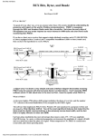
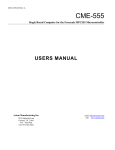
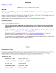
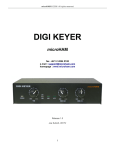
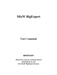
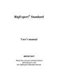
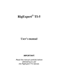
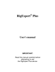
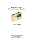
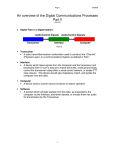
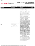
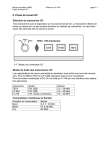
PSK31
A Handbook for PSK31 Users,
complete with dozens of transceiver
to PC sound card interface diagrams.
© 2000 By
Buck Rogers K4ABT
IT’S A “RAVE:”
To speak of it any other way, or in any manner other than; It’s a rave, would be understating its presence and impact
on the world of hobby communications. PSK31 is sweeping through the SWL and Amateur Radio ranks like a
brushfire. Not since the early days of FM repeaters has any mode inspired so much interest in HAM radio and short
wave radio monitoring than PSK31.
If you have a short-wave receiver that supports single-sideband reception, and a PC (486/100 MHz or above)
equipped with a Creative Labs™ compatible SoundBlaster (SB16 or later) sound card, then you have the ingredients
to receive PSK31.
SB16 Sound Card "LINE IN"
3.5 MM Stereo
SLEEVE
BucK4ABT
"A"
SLEEVE
3.5 MM Mono
Shielded Audio Cable, or Mono to Stereo cable.
BucK4ABT
RING N/C
TIP
To External Speaker
(3.5 mm)
TIP
RING NOT USED.
"B"
SB16 Sound Card "LINE IN"
3.5 MM Stereo
SLEEVE
SHIELD
RING N/C
BucK4ABT
1k ohm
SLEEVE
8 ohm
3.5 MM Mono
SHIELD
N/C
N/C
TIP
To External Speaker
FERRITE BEAD
RING NOT USED.
BucK4ABT
BUXFMR1K8
TIP
1000 ohm to 8 ohm
isolation transformer.
Figure 1
At figure one, I’ve drawn a very simple and basic interface diagram that makes receiving PSK31 easy for anyone
with the two basic items I’ve listed above. You’ll need the FREE software which I’ll talk about later in the text, but
first, I need to explain what PSK31 is.
What is PSK31?
As the name implies, PSK (phase shift keying) modulates the phase of a carrier, and the number ''31'' references the
actual bandwidth (31 Hz) occupied by the PSK31 signal.
The software that implements PSK31 with a Windows PC and soundcard is a program written and developed by Peter
Martinez G3PLX. Two of the most significant features that make this the ideal mode for digital communications is
the extremely narrow band width, and the fact that it is highly immune to noise and QRM.
Up front, phase modulation has more advantages than (morse code), CW. CW uses amplitude (On/Off) keying. In a
noisy or distorted propagation environment, the amplitude of a signal will shift and vary much more than the phase of
a signal. When compared to CW, PSK31 is a much more resourceful, and robust operating mode.
The baud rate used by PSK31 is 31.25 baud. This is fast enough to handle most operators manual typing capabilities,
a speed of about 50 words per minute. It is intended as a means of keyboard to keyboard communication between
two or more operators (oh happy day, we’re talking to each other again), using a very small amount of frequency
spectrum.
By comparing the small bandwidth of PSK31 and measuring its gain against a CW filter of 500 Hz; 10 * log (500/31)
dB = 12 dB, quickly reveals that a CW transmitter must put out 15 to 18 times more power than a PSK31 transmitter,
just to achieve the same signal to noise ratio at the receiving station. This is the reason the PSK31 operating mode
has gained so much popularity in such a very short period.
The end result is that a PSK31 station can operate with reduced power and smaller antenna installations. As an
example; My 20 meter, 14.073 MHz, antenna, is located in the attic of my garage (about 14 feet above ground), and
my DX70H runs around 35 watts output.
Now comes the real tease, just for the DX hounds among us. In the last three months, I’ve work over 75 countries,
and each morning I spot a new one that I have not yet worked. It gets better! For some reason… I think it’s because
PSK31 is so much fun…, I’m finding more DX stations on PSK31 than I’ve ever encountered on SSB and other
modes combined. At any given moment, day or night, it appears that 20 meters is always open.
Twenty meters is not the only band that has PSK31 activity, but it is a good place to start when you first begin
operating PSK31.
AND, IT’S ALMOST FREE:
When the prospective PSK31 user discovers PSK31 for the first time, a look of both extreme pleasure, and amazed
disbelief appears on their face. WOW, we’ve just discovered a mode that is so much fun, yet, it’s almost FREE!
After a few days of operating PSK31, the internet becomes obscured in the mist of all the fun we’re having “doing”
PSK31.
Nope, we don’t have to purchase a special terminal controller, no special radio, no heavy outlay of cash, and all you
have to do is obtain a copy of the ''FREE'' PSK31 software from the author of PSK31, Peter Martinez G3PLX.. at;
http://aintel.bi.ehu.es/psk31.html.
Another site that offers a great PSK31 program (also FREE) is:
AirLink Express:
http://www.airlinkexpress.org/download.html
I’ll go into more detail later about the use of DigiPan II and how we interface our computer sound card
and our transceiver. For now, take a moment to preview a screen shot of DigiPan 1.2, at photo “A”.
Photo “A”
Yes, there are a large number of PSK31 programs that support the PC, LINUX, and the MAC. We’ll also cover them
later in this article.
KUDOS ARE DUE THE AUTHORS OF PSK:
Before I get into interfacing our HF transceivers and the sound cards, I would be remiss if I didn’t give credit to the
author(s) of PSK.
Here, in his words is the background and the PSK31 philosophy, of and by Peter Martinez G3PLX.
PSK31 is the result of my belief that the present batch of "data" modes have left a gap in amateur radio operating, the
gap that was previously filled by AMTOR or even traditional RTTY, in which two or more operators chat to each
other on an open channel. Modes such as packet radio, Pactor, and others, are highly complex, are unsuited to multiway conversations, and in particular, the long block lengths introduce an unacceptable delay in the processing of text
such that even normal conversation is unpleasant and quick-break question/answer sessions are impossible.
The move to automated unattended message forwarding has left a gap in the person-to-person communication field,
and PSK31 is an attempt to remedy this situation with a simple but efficient code structure coupled with the narrowest
possible bandwidth, and with only enough error-correction to match typical typing-error rates, and with no timeconsuming synchronization, changeover, and ARQ processes.
The 31 baud BPSK modulation system used in PSK31 was introduced by SP9VRC in his SLOWBPSK program.
Instead of the traditional frequency-shift keying, the information is transmitted by patterns of polarity-reversals
(sometimes called 180-degree phase shifts).
This process can be thought of as equivalent to sending information by swapping-over the two wires to the antenna,
although, of course, the keying is more usually done back in the audio input into the transceiver. A well-designed
PSK system will give better results than the conventional FSK systems that amateurs have been using for years, and is
potentially capable of operation in much narrower bandwidths than FSK. The 31 baud data rate was chosen so that
the system will handle hand-sent typed text easily.
There is a problem with PSK keying which doesn't show up with FSK, and that is the effect of key-clicks.
We can get away with hard FSK keying at moderate baud rates without generating too much splatter, but polarity
reversals are equivalent to simultaneous switching-off of one transmitter and switching-on of another one in antiphase: the result being key-clicks that are TWICE AS BAD as on-off keying, all other things being equal.
So if we use computer logic to key a BPSK modulator such as an exclusive-or gate, at 31 baud, the emission would be
extremely broad. In fact it would be about 3 times the baudrate wide at 10dB down, 5 times at 14dB down, 7 times at
17dB down, and so on (the squarewave Fourier series in fact).
The solution is to filter the output, or to shape the envelope amplitude of each bit which amounts to the same thing.
In PSK31, a cosine shape is used. To see what this does to the waveform and the spectrum, consider transmitting a
sequence of continuous polarity-reversals at 31 baud. With cosine shaping, the envelope ends up looking like fullwave rectified 31Hz AC. This not only looks like a two-tone test signal, it IS a two-tone test signal, and the spectrum
consists of two pure tones at +/-15Hz from the center, and no splatter. Like the two-tone and unlike FSK, however, if
we pass this through a transmitter, we get inter-modulation products if it is not linear, so we DO need to be careful not
to overdrive the audio.
However, even the worst linear will give third-order products of 25dB at +/-47Hz (3 times the baud rate wide) and
fifth-order products of 35dB at +/-78Hz (5 times the baud rate wide), a considerable improvement over the hardkeying case. If we infinitely overdrive the linear, we are back to the same levels as the hard-keyed system.
There is a similar line of reasoning on the receive side. The equivalent to "hard-keying" on the receive side is a BPSK
receiver which opens a gate at the start of a bit, collects and stores all the received signal and noise during the bit, and
then "snaps" the gate shut at the end. This process gives rise to the receive-side equivalent of key-clicks, namely sidelobes on the receiver pass band. So, although this "integrate-and-dump" method is 100% efficient in the task of
sorting out signal from noise, it will only reject signals by 10dB at 3 times the baud rate wide and so on, the same
spurious rejection figures that we got as spurious emission figures for the transmit side.
The PSK31 receiver overcomes this by filtering the receive signal, or by what amounts to the same thing, shaping the
envelope of the received bit. The shape is more complex than the cosine shape used in the transmitter: if we used a
cosine in the receiver we end up with some signal from one received bit "spreading" into the next bit, an inevitable
result of cascading two filters which are each already "spread" by one bit.
The more complex shape in the receiver overcomes this by shaping 4 bits at a time and compensating for this intersymbol interference, but the end result is a pass band that is at least 64dB down at +/-31 Hz and beyond, and doesn't
introduce any inter-symbol interference when receiving a cosine-shaped transmission.
Contact Information:
Peter Martinez G3PLX
High Blakebank Farm
Underbarrow
Kendal
Cumbria LA8 8BN
United Kingdom
My thanks and with credits to Peter for permission to reprint his PSK31 philosophy here.
THE QUICK BROWN “VOX”
For this discussion, we will NOT consider using the VOX (voice operated relay) circuits in our transceiver to control
PSK31 changeover from transmit to receive and vice versa. Especially since most of us have a spare or extra serial
comport(s) that we can use to do the same thing, and without having the transceiver hiccup a transmitted signal every
time the sound card burps. As you will soon see, there is an easier way to handle the push-to-talk (PTT) function in
PSK31.
ATTENUATOR; YES OR NO:
Yes, we should consider the use of some level of attenuation either into the sound card or out of the sound card into
the transceiver. I think the easiest way to approach this is to understand first that modern day transceivers are
designed for inputs into the transceiver for SSB, FM, AFSK, RTTY, and in some cases, SSTV. We should maintain
the levels similar to those we normally use when using a microphone.
Since many transceivers that we will be using are beyond ten (10) years since their purchase, some of us will be using
the microphone port for our PSK31 input. If this is the case, and you plan to drive the microphone with your sound
card (LINE OUT), then the level from the sound card should be comparable to the output level of your microphone.
But I’ve already said that haven’t I? YES, I have, but I want to stress a point. In this case, we will need to employ
padding of about 40 DB. I refer to these attenuators as “pads.” This term comes from a time when we referred to it
as “padding the signal down.” For the new HAM, padding down of a signal can reference either audio or radio
frequencies (AF / RF).
TIP
FROM SOUND CARD "LINE OUT"
1K
100 K
BucK4ABT
SLEEVE
Ring Not Used
SHIELD/GROUND
ATTENUATOR (PADDING) APPROXIMATELY 40 DB.
Figure 2
To keep it simple, I’ve drawn an attenuator “pad” at figure two. Again, it is a device that is simple to build since it
employs only two resistors. Unless your sound card is a slam-dunk’n, speaker popper, you should be able to get by
with quarter watt sized resistors.
While many sound blaster™ compatible sound cards have the capability to be set for high or low level outputs, they
are almost always providing outputs which are much to high for the input level to the microphone port of our
transceiver.
Photo “B”
If you cannot use the sound card “Control Panel” in Windows (or Digipan, see Photo B) to decrease the output level
of your sound card to meet the level requirements of your microphone input, then you are about to construct the
resistive attenuator shown at figure two to reduce the LINE OUT level to your transceiver MIC port. The idea is to
keep your signal at a low enough level to have a clean PSK31 signal on the air.
With PSK31, the first thing I do is set my transceiver for normal single side-band (SSB) operation. I turn off any
speech processing and after I have the microphone level properly set for PSK31, I don’t change this setting again.
All future levels are set into and out of the sound card using the volume and wav controls built into the sound card
“control panel” software. In DigiPan II, these controls are easily accessed from the task bar at the top of the screen.
Simply click on “configure” and use the “Transmit Drive” (Photo B), command to properly drive the transceiver so
that no ALC action is observed. This is how I avoid causing phase distortion or overdriving the inputs of my
transceiver.
Photo “C”
Similarly, you can use the DigiPan II “configure” Icon on the task bar and select “Spectrum Drive” (Photo C) to set
the receive level to the sound card LINE IN.
While we’re discussing sound card I/O levels, in case of feedback (usually "motorboating"), which may be caused by
the common ground of the soundcard input and output, “MUTE” the “line in” ON THE "VOLUME CONTROL"
panel under Windows or in DigiPan configure/transmit/check ‘Mute’. This change will stop the sound in your PC
speakers, but it may also stop the motor-boating of your PSK31 transmit signal.
Let me say it again, in another way, so the message is well understood. The Microphone and Line inputs on the
Volume Control panel, controls the SOUND to the speakers (not the spectral display) and muting these inputs will
render no sound (receive) from the computer speakers, but the transceiver speaker can still be used to audibly monitor
the PSK31 signal if you so desire.
If you are using the external speaker jack for receive audio to the sound card, then a 3.5 MM plug and two-jack
splitter may be required to feed both an external speaker and the sound card. This is because the internal transceiver
speaker will be muted by the closed-circuit (opened) jack.
LET’S GET BUSY:
In figures 3, 4, 5, 6, and 7, I’ve drawn several full blown interface drawings and diagrams for specific makes and
model transceivers. Please notice that in most of the diagrams, I’ve use transformer coupling for both transmit and
receive audio paths/signals. In addition, I’ve used opto-coupling devices to further isolate and prevent any RF from
reaching the transceiver input or the sound card LINE IN or LINE OUT ports.
R
BUXFMR6K6
SOUND CARD
"LINE IN"
TIP
BucK4ABT
BLACK N/C
P
"
SLEEVE
RING NOT USED
"Patch OUT"
"RCA Jack"
SHIELDED
AUDIO CABLE
10K
TIP
BucK4ABT
SOUND CARD
"LINE OUT"
P
25K
SLEEVE
"
RING NOT USED
Patch In
"RCA Jack"
BUXFMR6K6
PIN 4 "RTS"
PIN 7 to 4N25, PIN 2 (Signal Gnd)
BucK4ABT
DB25 FEMALE
Alternate Serial (PTT) DB 25 Comport.
DB9 FEMALE
1
6
RTS
7
PHOTOTRANSISTOR
1500 ohms
1N4148
5
9
BucK4ABT
1
6
2
5
3
4
BucK4ABT
PTT
GND
TX "PTT"
"RCA Jack"
4N25 OPTOCOUPLER
(TIP)
As a starting point, go into the sound card parameters and set "LINE OUT" half open, and set "LINE IN" half open.
Ten-Tec OMNI series "Patch IN, Patch OUT, and PTT" ports to PC Sound Card for PSK31 mode.
Figure 3
If you are taking the constant level output of audio from your transceiver and driving the sound card then you can rest
assured you need to be very critical of levels into the sound card. Read your transceiver manual as it should tell what
the levels are at the various inputs and output jacks.
READY, SET, PSK31:
As an author of many books and magazine columns for the past 40 years, my typing speed is fluent at 60 to 70 words
per minute. My point is that I am hard pressed to keep up with the speed in which PSK31 handles my typing speed to
the target station. It's not uncommon to read most stations at 30 to 50 wpm.
PSK31 offers us plenty of fun and so far, it's been a ''rush'' for me. In my 50 years as a HAM, this mode is the most
seductive of them all.
Download the program and connect only the sound card LINE IN, to your HF transceiver external speaker port and
tune to 14073.00 LSB and watch the waterfall screen for vertical, yellow, scrolling, PSK31 signals. It won't be long
before your back at this page, looking up the transceiver to sound card interface diagram so you can begin full
operation with PSK31.
The following is a list of frequencies (in kHz) where you may find more PSK31 activity are:
1838.150
3580.150
7035.150
10140.150
14070.150
18100.150
21080.150
24920.150
28120.150
Because I am most familiar with the DigiPan 1.2/1.4 PSK31 software, I will use it as a reference during my
explanation for setting up the transceiver and sound card levels.
First we’ll set the soundcard output level to approximately one third to half-scale (click the speaker symbol on the
Windows taskbar). Connect a dummy load to the transceiver antenna output and click on the DigiPan ‘TX’ menu
button.
SOUND CARD
"LINE IN"
P/N=BUXFMR1K8
1k
8 ohm
TIP
TO EXTERNAL
SPEAKER
TIP
BucK4ABT
N/C
BucK4ABT
N/C
P
SLEEVE
RING NOT USED
SLEEVE
SHIELDED
AUDIO CABLE
RING NOT USED
4700 ohms
TIP
25K POT
BucK4ABT
SOUND CARD
"LINE OUT"
N/C
P
1:1
N/C
SLEEVE
P/N= BUXFMR6K6
Pin 4 = "RTS"
Pin 7 = Signal GND
Pin 20
DTR
BucK4ABT
DB25 FEMALE
ALTERNATE SERIAL
PORT (DB25).
PHOTOTRANSISTOR
DTR4
6
2
5
3
4
5
1
9
6
7
1200
BucK4ABT
DB9 FEMALE
1
RTS
ohms
BucK4ABT
1N4148 or 1N914
PTT
GND
PS-2601 or 4N25 Opto-Coupler
ALINCO or KENWOOD HF TRANSCEIVER WITH 8 PIN MICROPHONE PORT.
Figure 4
Next, let’s make sure we have our transceiver set for LSB (lower side-band) operation, and the AGC set for Slow
(recovery). We’re now set to begin our on-the-air (dummy-load) setup.
The easiest way to perform this one-time procedure is to set the transceiver frequency to 14073.000. Set the DigiPan
‘View’ ‘Frequency Display’ selection to ‘LSB’ and the ‘Configure’ “Spectrum Start” (see Photo D) frequency to
“14073.000.” Notice the graduation of the frequency is 14069… to 14073, left to right.
Using your favorite watt meter and dummy load connected to the output of your transceiver, click on the DigiPan
‘TX’ menu button and adjust the Speaker volume slider on the Windows taskbar tray for an output power reading of
about one third to one half the power you would normally see when operating CW. DO NOT operate your
transceiver above half its maximum power level rating!
Once you have the power level set, type a few characters and watch the power meter. As you type, the text you are
sending should cause the meter pointer to have a slight jitter. If you have the LINE OUT/MIC IN level set properly,
you should see the power move slightly upwards. At no time should you see the power level go above 50% or your
transceiver’s rated power output. If it does go higher, simply turn the Transmit Drive level down, using the
“configure/transmit drive/volume control/ in DigiPan 1.2.
Photo “D”
SOFTWARE, SOFTWARE, EVERYWHERE:
There’s plenty of software to help you get on the air with PSK31. You can choose the one you like best and of course
some of your decisions will be based on the particular operating system for your computer.
Be sure you read the PSK31 software user’s manual or the “help” files that relate to the software you plan to use.
In the next few paragraphs, I’ll try to name a few software packages for PSK31 operation. Before I go there, I’d like
to point out that so much of this software is FREE, however, the software writer and author cannot live by bread
alone; He/she must have peanut-butter, and peanut-butter cost money!
Which ever software you finally choose, remember the author of that software package dedicated his or her time to
making your hobby more fun. If you like the software, send the author a small donation as a sign of your appreciation
for their contribution to making your hobby fun and exciting. By sending a small contribution to the software author,
you are also encouraging them to extend additional effort to add more features and updates for your future enjoyment.
DECISIONS, DICISIONS:
The main distribution point for Peter G3PLX's
http://www.kender.es/~edu/download/p31sbw.zip
implementation
reference
software,
is
at:
SOUND CARD
"LINE IN"
Receive Audio
TIP
BucK4ABT
Shielded
Audio Cable
SLEEVE
RING NOT USED
SHIELDED
AUDIO CABLE
RING NOT USED
4700 ohms
Tx Audio
TIP
BucK4ABT
SOUND CARD
"LINE OUT"
600/600 ohms 1:1
1K
SLEEVE
Pin 4 = "RTS"
BUXFMR6K6
Pin 7 = Signal GND
Pin 20
DTR
BucK4ABT
DB25 FEMALE
ALTERNATE SERIAL
PORT (DB25).
PHOTOTRANSISTOR
DTR4
1
6
2
5
5
1
9
6
PTT
ACC2
(Solder Side View)
7
BucK4ABT
DB9 FEMALE
(TIP)
RTS
1200
ohms
1N4148 or 1N914
3
4
BucK4ABT
GND
4N25 OPTOCOUPLER
As a starting point, go into the sound card parameters and set "LINE OUT" half open, and set "LINE IN" half open.
KENWOOD TS-690S, and TS-940 HF transceivers to PC SB16 for PSK31 and SSTV use.
Figure 5
DIGIPAN:
There is a new version this super (FREEWARE) PSK31 program called Digipan 1.4 with many more features added
since version 1.0 and 1.2. DigiPan is written by Howard KH6TY and Nick "MixW32" UT2UZ. It is the first PSK31
program that has a panoramic (waterfall) view of the entire audio spectrum that I use. In DigiPan 1.2, I can instantly
tune a new station with either the click of the mouse or by using the left or right arrow keys. The latter (arrow keys)
drive a new built-in “signal-seeker” feature. Add to this, the many macros that can be called into play with just the
click of your mouse.
DigiPan uses digital signal processing (DSP) to do all these features and then decode the resulting PSK31 sounds into
characters on the receive screen. The display shown at photo A, is how a typical DigiPan spectrum (panoramic
waterfall) window appears.
A bright yellow bar with the diamond-shaped cursor in it is a PSK31 station. To the left and right of the station select
cursor, are other PSK31 stations. Some appear weaker and others will display brighter, which indicates stronger
signals. Although some signals in the display appear weak, they will still print perfect copy. In many cases, I’ve
clicked on almost invisible streaks on the DigiPan 1.2 display and printed perfect text.
The most recent receive signals are displayed at the top of the DigiPan 1.2 waterfall display. To the right of the
cursor, is another PSK31 station that is almost too weak to copy.
To tune and receive any of these stations, it is only necessary to point to the station signal with the mouse and click!
The diamond-shaped cursor will jump immediately to the center of the station signal and the text from the station will
begin to appear on screen in the receive window.
During an idle moment, you can read the IMD of the selected station on the lower feature bar in DigiPan. The IMD
reading of the station displayed in photo “A” is minus 23.5. A good signal and ideal IMD according to DigiPan.
Other sections of the DigiPan screen are devoted to buttons to control the functions of DigiPan, and select keys for the
activation of a large number macros. The “text” button on the task bar enables the operator to choose any number of
text files to send, including the familiar “BRAG.TXT” that all us ole RTTY ops are familiar with.
Just a word to the wise; In order for DigiPan to provide a panoramic display with point-and-click tuning of stations, it
is necessary for our transceiver’s to provide both panoramic reception and transmission. The receive band pass
should be capable of receiving a large number of PSK31 stations at one time. So far, all the transceivers I’ve operated
or interfaced, have this capability. Even my little Radio Shack receiver, connected to the laptop sound card receives
and displays PSK31.
BUXFMR6K6
SOUND CARD
TIP
"LINE IN"
Rx Audio
BucK4ABT
P
Gnd/Shield
SLEEVE
RING NOT USED
SHIELDED
AUDIO CABLE
RING NOT USED
3 .3uF
@35V
4700 ohms
25K
TIP
4k7
BucK4ABT
- +
SLEEVE
GND/Shield
"C"
BUXFMR6K6
PIN 4 "RTS"
TIP
PIN 7 to 4N25, PIN 2 (Signal Gnd)
*
Components "C" and "R" must
be used in this interface. Values
may vary slightly, but "R" & "C"
are absolutely necessary!
IMPORTANT NOTE !
BucK4ABT
DB25 FEMALE
1
6
RTS
7
5
9
BucK4ABT
BucK4ABT
TIP
SLEEVE
6
2
5
PTT
3
4
GND
k
1
1N4148
2
1200 OHMS
DB9 FEMALE
RING
PHOTOTRANSISTOR
Alternate Serial (PTT) DB 25 Comport.
(TIP)
*
2
SOUND CARD
"LINE OUT"
PSK Tx Audio
P
"R"
*
BucK4ABT
1N4148 or 1N914
4N25 OPTOCOUPLER
As a starting point, go into the sound card parameters and set "LINE OUT" half open, and set "LINE IN" half open.
YAESU FT-767 & FT-847 3.5 mm Data I/O to PC Sound Card for PSK31 mode.
Figure 6
MixW32
Now if you’re searching for a Windows 95, 98 or NT program that will put your Sound Card through its paces, go to:
''http://tav.kiev.ua/~nick/mixw/mixw.htm'' and look into MixW32 written by Nick Fedoseev, UT2UZ. MixW32
stands for a Mixture of different modes for HAM Radio. MixW32 doesn't require a TNC to operate and the only
requirement is that you have a computer with a compatible soundcard installed along with a Windows operating
system. It supports PSK31 BPSK and QPSK and a new mode named FSK31.
Nick has another commercial version (Rev 1.37) that also offers Pactor Rx, VHF/HF Packet Rx and (Tx (with
keying interface), CW Tx and Rx.
Nick’s homepage is at; http://tav.kiev.ua/~nick/my_ham_soft.htm.
600 to 600 ohms
1:1
SOUND CARD
"LINE IN" TIP
Receive Audio
P
SLEEVE
RING NOT USED
SHIELDED
AUDIO CABLE
RING NOT USED
TIP
25K
Shield or Gnd
BUXFMR6K6
4K7
(4700 ohms) P
SLEEVE
Transmit Audio
R
"
SOUND CARD
"LINE OUT"
Shield or Gnd
ICOM TRANSCEIVERS 8 pin DIN ACC(1) TO PC Sound Card
D
E
IC-725, IC-726, IC-735, IC-737, IC-746, IC-756, IC-760, IC-761, IC-775, IC-781, IC-820,
IC-970, ..etc.. IC-275, IC-375, IC-575, IC-721, IC-732, IC-723, IC-729, IC-736, IC-780
5
6
9
7 RTS
BucK4ABT
1200
ohms
1K2
4N25 OPTOCOUPLER
PHOTOTRANSISTOR
1
6
"
1N4148 or 1N914
1
GND
5 Push To Talk (PTT)
2
DB9 FEMALE
TO UNUSED SERIAL PORT.
3
4 RADIO SHIELD/GND
BucK4ABT
Figure 7
WinPSK:
There is a new version of WinPSK by Moe AE4JY. It adds two interesting features, the first is a new user interface
that favors the disabled ham who cannot use a mouse, but through the use of the function keys and Macros, it’s a
snap to use. The second one that Moe has produced has a PskCORE DLL that is available in binary along with
instructions. You can go to Moe’s page at: http://www.qsl.net/ae4jy/
I keep a copy of the Moe’s user manual in .pdf format and his technical supplement close by. It is a must, plus a real
pleasure to read. Here you can learn both implementation details and the theory and operation of PSK31.
Zakanaka:
Yes, it is called,”Zakanaka” It now employs a waterfall type display. As I understand, the PSK31 code has been
made available as a standalone program. So far, I’ve not been able to obtain a copy of Zakanaka, written by Bob
Furzer K4CY.
LINUX:
Amateur and PSK31 linux applications can be found at: ftp://metalab.unc.edu/pub/Linux/apps/ham/
Macintosh:
There is a shareware program called Multimode by Chris N3JLY. It enables PSK31 operation for the Macintosh user.
Go to: http://www.blackcatsystems.com/software/multimode.html
And…. Just in case I’ve not provided you with enough PSK31 fodder here in “BUX Bitz, Bytez, and Baudz,” then
have a look at:
http://www.packetradio.com/psk31.htm
Have fun communicating via PSK31.
73 de Buck Rogers K4ABT
Visit:
www.packetradio.com
or
www.amateuradio.org
* Sound Blaster 16 and progressive releases of “Sound Blaster” are trademark(s) of Creative Labs.
My thanks to the following Amateurs for their permissions, contributions, and support for this handbook:
Peter Martinez,
Nick Fedoseev,
Howard “Skip” Teller,
Ernie Mills,
G3PLX
UT2UZ,
KH6TY
WM2U
In the pages that follow, you’ll find many PSK31 interface diagrams. Although most of these diagrams
were tested in on-the-air operation, I accept no responsibility for errors, mistakes or omissions. Double
check all work and consult equipment manuals to verify use and revisions.
ISO-KIT-1
for Alinco and Kenwood transceivers with standard (screw-on) 8 pin mic connector.
ISO-KIT-2
A Universal parts kit for various transceivers with the standard 8 pin screw-on microphone connector.
ISO-KIT-3
for YAESU FT-847 and similar transceivers with 3.5 mm (1/8") stereo data I/O jack.
ISO-KIT-4
for YAESU FT-990 and FT-1000 and similar transceivers with 5 pin DIN data I/O jack.
ISO-KIT-5
ISO-KIT-75767
for ICOM IC-746, IC 756, IC-775 ...etc, and similar transceivers with 8 pin DIN ACC(1) data I/O jack.
for YAESU FT-757, FT-767, Collins KWM-380, and similar transceivers with RCA Data I/O and PTT jacks.
ISO-KIT-TR7A
ISO-KIT-1K990
ISO-KIT-706MDIN
for the Drake TR7 and TR-7A transceivers with standard 4 pin mic connector.
for YAESU and transceivers w/5 pin DIN Pkt/Data Port.
for ICOM IC-706 MKII and similar w/6 pin Mini DIN.
ISO-KIT-11
for ICOM, YAESU, Kenwood, and similar transceivers with 8 pin screw-on ''standard'' microphone port.
ISO-KIT-706RJ45
ISO-KIT-TS-830
for ICOM IC-706 and similar w/8 pin RJ-45 microphone port.
for KENWOOD HF transceivers with 4 pin microphone connectors.
ISO-KIT-K505DSP
for KACHINA 505 DSP, HF, CPU based transceivers with DB25 Data I/O port connectors.
ISO-KIT-AR25008P
ISO-KIT-TT4P
for the RANGER AR-2500 and similar 8 pin Mic I/O.
for the Ten-Tec 4 pin mic and similar I/O.
ISO-KIT-TTOMNI
ISO-KIT-TT25S
for the Ten-Tec OMNI series with RCA ''Patch IN, Patch OUT, and PTT'' jacks.
for the Ten-Tec, DRAKE and other transceivers with 1/4 inch Stereo Mic connector I/O jacks.
ISO-KIT-UHR5P
ISO-KIT-FTMDIN
ISO-KIT-RCA2MO
for the UNIDEN HR-2510 and HR-2600 5 pin mic and similar I/O
for the Yaesu FT-100 6 pin Mini DIN and similar I/O ports.
for the Yaesu FT-1000 D using RCA jacks and similar I/O ports.
ISO-KIT-KW13PD
(kit includes the 13 pin DIN male connector.)
for the Kenwood transceivers with 13 pin DIN ACC2
accessory I/O ports.
ISO-KIT-IC13PD
(kit includes the 13 pin DIN male connector.) for the ICOM transceivers with 13 pin DIN ACC2 accessory I/O
ports.
The ISO-KIT numbers beneath each set of diagrams above reference their catalog numbers on the web pages at:
http://www.packetradio.com/psk31.htm
You may wish to visit this site for updates and new additions to the PSK31 interface diagrams.
THANK YOU FOR SUPPORTING THE WEB PAGES AT:
www.PacketRadio.com and www.PacketRadio.com/PSK31.htm
73 de BucK4ABT
Visit;
http://www.buxcomm.com/catalog
This document is copyright; 2000
By G. E. “Buck” Rogers Sr.
All rights reserved.