1
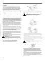
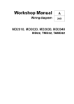
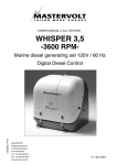
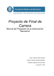
INSTRUCTION BOOK
MD22L, MD22, TDM22
7736943 - Gedownload van www.volvopenta.com 8-2-2009 23:14:15
California
Proposition 65 Warning
Diesel engine exhaust and some of its constituents are known to the
State of California to cause cancer, birth defects, and other reproductive harm.
Owner’s Manual
Marine Diesel Engines
MD22L, MD22, TMD22
7736943 - Gedownload van www.volvopenta.com 8-2-2009 23:14:15
Contents
Safety precautions
Maintenance
Introduction .................................................................... 2
General information ..................................................... 4
Running-in ...................................................................... 4
Warranty ......................................................................... 5
Certificated engines ....................................................... 6
Check daily before starting ........................................... 20
Check every 14 days .................................................... 20
Check every 50 hours of operation .............................. 21
Check every 200 hours, or least once a year ............... 22
Service every other season .......................................... 24
Other service intervals ................................................. 25
Instruments ................................................................... 9
Laying-up
Control ........................................................................ 12
Operation
Before starting .............................................................. 13
Starting ......................................................................... 13
Stopping ....................................................................... 15
In risk of frost ................................................................ 15
General engine information
Inhibiting ....................................................................... 26
Recommissioning, launching ....................................... 29
Painting ........................................................................ 30
Propellers ..................................................................... 31
Troubleshooting
Problem - possible causes ........................................... 32
Emergency procedures ................................................ 33
Technical data
Coolant ......................................................................... 16
Venting the fuel system ................................................ 17
Emergency stop ........................................................... 17
Electrical system .......................................................... 18
Fuses ........................................................................... 19
Battery .......................................................................... 19
Engine .......................................................................... 34
Reverse gear, S-drive .................................................. 35
Electrical system
Wiring diagrams ........................................................... 36
CALIFORNIA
Proposition 65 Warning
Diesel engine exhaust and some of its constituents are known to
the State of California to cause cancer, birth defects, and other
reproductive harm.
1
Safety precautions
Introduction
This Owner’s Manual contains the information you will
need to operate the engine correctly. Check that you
have the correct Owner’s Manual for your engine.
Read the book carefully before operating or servicing the engine. Incorrect operation or servicing of the
engine could result in personal injury or material damage
as well as damaging the engine itself. If you do not
understand or are uncertain on any operation in this
book, contact your dealer who can explain or demonstrate the procedure for you.
Important
7736943 - Gedownload van www.volvopenta.com 8-2-2009 23:14:15
In this manual and on the engine you will find the following special warning symbols.
WARNING! Possible danger of personal injury,
damage to property or mechanical malfunction if
the instructions are not followed.
Read the Owner’s Manual.
Below is a summary of the risks and safety precautions
you should always observe or carry out when operating
or servicing the engine.
Check that the warning or information labels on
the engine are always clearly visible. Replace
labels which have been damaged or painted
over.
Always turn the engine off before starting
service procedures. Avoid burns. Take precautions to avoid hot surfaces and liquids in supply
lines and hoses when the engine has been
turned off immediately prior to starting work on it
and it is still hot.
Reinstall all protective parts removed during
service operations before starting work on the
engine. Make a point of familiarizing yourself
with other risk factors, such as rotating parts
and hot surfaces (exhaust manifold, Turbo unit,
charge pipe, starter heater etc.).
Approaching an engine which is operating is a
safety risk. Loose clothing or long hair can
fasten in rotating parts and cause serious
personal injury.
If the service operation requires that the engine
is operating let your Penta authorized dealer
carry out the work. If working in proximity of an
engine which is operating, careless movements
or a dropped tool can result in personal injury.
2
Immobilize the engine by turning off the power
supply to the engine at the main switch (breakers) so it is impossible to start, and lock the
switch (breakers) in the OFF position before
starting work. Set up a warning notice at the
engine control point or helm.
Engines with Turbo compressors: Never start
the engine without installing the air cleaner
(ACL). The rotating compressor parts in the
Turbo can cause serious personal injury.
Foreign objects entering the intake ducts can
also cause mechanical damage.
Engines with intake air pre-heating: Never use
starting spray in the air intake. Use of such
products could result in an explosion in the air
intake pipe due to the hot-spot pre-heater.
Danger of personal injury.
Do not open the filler cap for the engine coolant
(freshwater cooled engines) when the engine is
hot. Steam or hot engine coolant can be ejected
and any pressure in the system will be lost.
Open the filler cap slowly and release coolant
system pressure (freshwater cooled engines), if
the filler cap or drain cock must be opened, or if
a plug or engine coolant line must be removed
on a hot engine. Steam or hot coolant can be
ejected.
Stop the engine and close the bottom valve
before carrying out operations on the cooling
system.
Only start the engine in a well-ventilated area. If
operating the engine in a closed area ensure
that there is exhaust ventilation leading out of
the work area to remove exhaust gases and
crankcase ventilation emissions.
Anti-corrosion agents are hazardous to health.
Read the instructions on the product packaging!
Anti-freeze agents are hazardous to health.
Read the instructions on the product packaging!
Certain engine conservation oils are inflammable. Some of them are also dangerous if
breathed in. Ensure good ventilation in the work
place. Use a protective mask when spraying.
Hot oil can cause burns. Avoid getting hot oil on
the skin. Ensure that the lubrication system is
not under pressure before carrying out any
work. Never start or operate the engine with the
oil filler cap removed, otherwise oil could be
ejected.
7736943 - Gedownload van www.volvopenta.com 8-2-2009 23:14:15
Never allow an open flame or electric sparks
near the battery area. Never smoke in proximity
to the batteries. The batteries give off hydrogen
gas during charging which when mixed with air
can form an explosive gas. This gas is easily
ignited and highly volatile. Incorrect connection
of the battery can cause sparks sufficient to
cause an explosion with resulting damage. Do
not shift the connections when attempting to
start the engine (spark risk) and do not lean
over any of the batteries. Refer to instructions in
the Owner’s Manual.
Always ensure that the Plus (positive) and
Minus (negative) battery leads are correctly
installed on the corresponding terminal posts on
the battery. Incorrect installation can result in
serious damage to the electrical equipment.
Refer to the wiring diagrams.
Always use protective goggles when charging
and handling the batteries. The battery electrolyte contains extremely corrosive sulfuric acid. If
this should come in contact with the skin,
immediately wash with soap and plenty of
water. If battery acid comes in contact with the
eyes, immediately flush with water and obtain
medical assistance.
Turn the engine off and turn off the power at the
main switches (breakers) before carrying out
work on the electrical system.
Clutch adjustments, where a clutch is fitted,
must be carried out with the engine turned off.
Use the lifting eyes fitted on the engine/reverse
gear when lifting the drive unit. Always check
that the lifting equipment used is in good
condition and has the load capacity to lift the
engine (engine weight including reverse gear
and any extra equipment installed).
perpendicular as possible to the upper side of
the engine.
If extra equipment is installed on the engine
which alters its center of gravity a special lifting
device is required to obtain the correct balance
for safe handling.
Never carry out work on an engine suspended
on a hoist.
The components in the electrical system, the
ignition system (gasoline/petrol engines) and in
the fuel system on Volvo Penta products are
designed and manufactured to minimize risks of
fire and explosion.
Using parts that are not Original Volvo Penta
parts which do not correspond to the demands
above, can result in fire or explosion on board.
Any type of damage which is the result of using
replacement parts that are not original Volvo
Penta replacement parts for the product in
question will not be covered under any warranty
or guarantee provided by AB Volvo Penta.
Fuel filter replacement should be carried out on
a cold engine in order to avoid the risk of fire
caused by fuel spillage on the exhaust manifold.
Always cover the alternator, if it is located under
the fuel filter. The alternator can be damaged by
spilled fuel.
Always use protective gloves when detecting
leaks. Liquids ejected under pressure can
penetrate the body tissues and cause serious
injury. Danger of blood poisoning.
Always use fuels recommended by Volvo Penta.
Refer to the Owner’s Manual. Use of fuels that
are of a lower quality can damage the engine.
On a diesel engine poor quality fuel can cause
the actuating rod to hang and the engine to
overrev with resulting risk of damage to the
engine and personal injury. Poor fuel quality can
also lead to higher maintenance costs.
Observe the following when cleaning with highpressure water jets. Never point the water jet at
seals, rubber hoses or electrical components.
Never use high pressure jets when washing the
engine.
To ensure safe lifting and avoid damage to
components installed on the top of the engine
use an adjustable lifting beam. All chains and
cables must run parallel to each other and as
3
General Information
Welcome aboard
Fuel and lubricants
Thank you for choosing a Volvo Penta marine engine.
Only use lubricants and fuels recommended under
“Technical Data”. Use of other classifications can cause
malfunctions and reduced service life.
Volvo Penta have been building marine engines since
1907. Quality, operating reliability and innovation have
made Volvo Penta a world leader in the marine engine
industry.
As owner of a Volvo Penta marine engine we would also
like to welcome you to a worldwide network of dealers
and service workshops to assist you with advice, service
requirements and spare parts. Please contact your
nearest authorized Volvo Penta dealer for assistance.
Spare parts
WARNING! The components in the electrical
system and in the fuel system on Volvo Penta
products are designed and manufactured to
minimize the risk of fire and explosion.
Using parts that are not Original Volvo Penta
parts and which do not correspond to the
demands above, can result in fire or explosion
on board. Any type of damage which is the
result of using replacement parts that are not
original Volvo Penta replacement parts for the
product in question will not be covered under
any warranty or guarantee provided by
AB Volvo Penta.
We would like to wish you many pleasant voyages.
AB VOLVO PENTA
Technical Information
7736943 - Gedownload van www.volvopenta.com 8-2-2009 23:14:15
Your new boat
Every new boat has it own special characteristics. Even
experienced boat owners are advised to note carefully
how the boat behaves at different speeds, weather
conditions and loads. If your boat and engine combination permit high-speed use, we strongly recommend that
a safety breaker is fitted, regardless of the type of boat. If
your boat is not fitted with a safety breaker contact your
Volvo Penta dealer who can assist you in selecting one.
Running-in
A new marine engine requires a running-in period of 20
operating hours. Run the engine at varying engine
speeds, but not over a maximum of 3/4 throttle opening
for the first two hours. For the next 8 hours run the
engine in the same way, but with max. 2 minute periods
at wide open throttle (WOT). During the final 10 hours
increase wide open throttle periods to 5–10 minutes at a
time. Reduce the throttle opening to idle periodically to
allow the engine temperature to drop. During the running-in period never run the engine for long periods at a
constant engine speed. It is normal for the engine to use
more engine oil during the running-in period. Make a
point of checking the engine oil level more frequently
during the running-in period than during normal operation. Carry out the First Service Inspection after the initial
20-hour running-in period.
Safety
Everyone wants and expects to have a problem-free and
pleasant time when they take their boat out. To help you
do this we have provided a check-list below which can of
course be added to according personal experience. A
major area is naturally the engine, its equipment and that
the boat in general is properly maintained.
Planning your trip
– Get out up-to-date charts for the route planned
– Calculate distance and fuel consumption
– Note down if there are fuel points on your planned
course
– Tell friends or relatives about your trip plans
Boat equipment
– Rescue and emergency items such as life-vests and
signal rockets. Does everyone know where they are?
– Spare parts on board, for example: Kit with water
pump impeller etc.
– Proper tools for the equipment
– Fire extinguisher (checked and charged)
4
Our joint responsibility
Maintenance and care
Volvo Penta continually commits a considerable part of
its development resources towards minimizing the
environmental impact of its products. Examples of areas
where we are always looking for improvements are;
exhaust emissions, sound levels and fuel consumption.
– PDC (Pre Delivery Commissioning) delivery undertaking, for marine engines: PDC enables us to ensure that
Volvo Penta products operate correctly after installation
in a boat, and further that the end-user gets acquainted
with the product, its functions and care (refer to the
Warranty and Service book). Delivery undertaking “PDC“
is carried out at the time of the delivery of the boat to the
end-user. The cost of this work is covered by the Volvo
Penta International Limited Warranty.
Regardless of whether your Volvo Penta engine is
installed in a boat used for pleasure or in commercial
operation, incorrect operation or improper maintenance
of the engine will result in disturbance or damage to the
environment.
7736943 - Gedownload van www.volvopenta.com 8-2-2009 23:14:15
In this Owner’s Manual there are a number of service
procedures, which, if not followed will lead to a deterioration of engine characteristics with regard to how it effects
the environment, its service life and cost of operation.
Always follow the recommended service intervals and
make a habit of checking that the engine is operating
normally every time you use it. One example is excessively smoky exhaust. Contact an authorized Volvo
Penta workshop if you cannot correct the fault yourself.
Bear in mind that most of the chemicals used around
boats are harmful to the environment if used incorrectly.
Volvo Penta recommends the use of bio-degradable
degreasing agents for all cleaning. Always dispose of
engine and transmission oil waste, old paint, degreasing
agents and cleaning residue etc. at proper disposal
areas so they do not harm the environment.
Adapt speed and distance during your boat trips so that
swell and noise generated by the boat do not disturb or
harm wildlife, moored boats, landing stages etc. Wherever you land or cruise, please show consideration and
always leave the areas you visit as you would like to find
them yourself.
Warranty and guarantee
A Service and Warranty Book with conditions for Volvo
Penta’s International Limited Warranty is supplied with
every engine. Contact your nearest Volvo Penta dealer
or importer for your copy if you have not received one.
Some markets can have other warranty conditions
depending on national legislation and regulations. These
conditions are provided by the Volvo Penta importer or
distributor for the market in question. If you wish to have
a copy of the conditions please contact your local Volvo
Penta representative.
– First Service inspection, for marine engines: A first
Service Inspection must be carried out after operating
the engine for 20–50 hours or within 180 days from the
delivery date, or the end of the first season, whichever
occurs first. Labor and material costs in connection with
the First Service Inspection are not covered by the Volvo
Penta International Limited Guarantee (for checklist see
your Warranty and Service book).
Regular maintenance should be carried out after the First
Service Inspection in accordance with the maintenance
scheme in this book. Any work carried out in addition to
maintenance services should be documented (refer to
the Warranty and Service book)
It is an absolute condition for the Volvo Penta International Limited Warranty to apply that the PDC Delivery
undertaking and First Service Inspection have been
carried out by an authorized Volvo Penta Service dealer.
Volvo Penta Service
Volvo Penta has a comprehensive dealer network that
offers both service and spare parts for Volvo Penta
engines. Volvo Penta dealers are carefully selected and
then trained in order to provide customers with professional assistance on engine service and repairs. These
dealers have the special tools required to carry out the
work and the test equipment that ensures a high service
standard. They are required to keep a stock of Volvo
Penta Original Spare Parts and accessories that cover
most requirements. When ordering service or spare parts
always quote the complete engine and/or drive/reverse
gear model designation and serial number. These are
stated on the engine product plate and on a label on the
engine valve cover.
Warranty Registration Card
The Warranty Registration Form (North American
market) or Warranty Card (other markets) should always
be filled out and sent in by the vendor. Make sure that
this has been done, since refusal of warranty can occur if
no proof of the delivery date can be provided.
5
Certificated engines
Important information for engines certificated for
Lake Constance and Switzerland
All Volvo Penta engines and products are developed to
minimize environmental impact.
7736943 - Gedownload van www.volvopenta.com 8-2-2009 23:14:15
National and regional legislation is not identical in all the
markets where Volvo Penta sells its products. Occasionally legislation requires that we build special engine
variants, or that an engine must be approved in advance,
that is, certificated by the local authorities.
An engine with certification means that we, as the
manufacturer, guarantee that all engines manufactured
are of the same type as the certificated and approved
example. Certification is not only a requirement covering
engines from the factory, but also that engines in use
must meet the environmental demands set for that
engine. In order for Volvo Penta as the manufacturer to
take responsibility for engines in use, certain requirements pertaining to service and spare parts must be met.
We do not wish to discourage owners from carrying out
service work themselves, rather the opposite since an
owner can quickly notice if an engine is not operating
normally. However, a number of service operations
demand access to special expertise, workshop manuals,
special tools and other equipment designed for the
engines. These service operations may only be carried
out by an authorized Volvo Penta Service workshop.
Always contact your Volvo Penta dealer if you are not
sure about anything concerning your engine’s function or
maintenance.
As an owner or operator of a certificated Volvo Penta
engine it is important that you are aware of the following:
IMPORTANT! Use only VOLVO PENTA original
spare parts. The use of spare parts other than
VOLVO PENTA original spare parts will
invalidate AB VOLVO PENTA’s responsibility
for the engine specification being in accordance with the certificated variant. VOLVO
PENTA accepts no responsibility or liability for
any damage or costs arising through the use of
replacement parts other than original VOLVO
PENTA replacement parts for the product in
question.
Identifying Numbers
Immediately after you have taken delivery of your boat,
make a note of the serial number and model designation
of the engine and drive as well as the shield or reverse
gear. Include the serial number and model designation of
the boat and any extra equipment. This information is
necessary when you contact your Volvo Penta or boat
sales representative for service and spare parts. Take a
copy of the information and keep it in a safe place so it is
available should the boat be stolen.
Engine type .....................................................................
Serial No. ........................................................................
Drive type ........................................................................
Serial No. ........................................................................
l
The Service Intervals and maintenance operations
recommended by Volvo Penta must be followed.
l
Only Volvo Penta Original Spare parts intended for
the certificated engine may be used.
Serial No. ........................................................................
l
Service work on the ignition system, ignition settings
and fuel injection system (gasoline/petrol) or injection
pumps, pump settings and injectors (diesel) must
always be carried out by an authorized Volvo Penta
workshop.
Propeller designation ......................................................
l
l
l
The engine may not be altered or modified in any
way, with the exception of accessories and service
kits developed by Volvo Penta for that engine.
No modifications to the exhaust pipes and air supply
ducts for the engine room (ventilation ducts) may be
undertaken as this may effect exhaust emissions.
Any seals on the engine may not be broken other
than by authorized persons.
Reverse gear type ...........................................................
Boat type .........................................................................
Serial No. ........................................................................
Other equipment .............................................................
.........................................................................................
.........................................................................................
.........................................................................................
.........................................................................................
.........................................................................................
© 1995 AB VOLVO PENTA
All rights to changes or modifications reserved.
Printed on environmentally-friendly paper
6
7736943 - Gedownload van www.volvopenta.com 8-2-2009 23:14:15
Introduction
MD 22L, MD 22, TMD 22 / MS2L, MS2A
1.
2.
3.
4.
5.
6.
7.
Fuel liftpump
Oil dipstick
Filler cap for lubricating oil
Fuel filter
Reverse gear serial number
Alternator
Exhaust outlet
8.
9.
10.
11.
12.
13.
Raw water pump
Filler cap
Induction manifold
Pipe for oil bilge pump
Oil filter
Oil dipstick, reverse gear
7
7736943 - Gedownload van www.volvopenta.com 8-2-2009 23:14:15
MD 22L, MD 22, TMD 22 /120S
1.
2.
3.
4.
5.
6.
7.
8.
9.
10.
11.
12.
13.
14.
8
Fuel liftpump
Oil dipstick
Filler cap for lubricating oil
Fuel filter
S-drive serial number
Zinc anode
Alternator
Exhaust outlet
Raw water pump
Filler cap
Induction manifold
Pipe for oil bilge pump
Oil filter
Oildrainage, drive
Instruments
There are two types of instrument panels, “Standard” and
“De luxe”.
1. Rev. counter
Standard
Full throttle: operating range,
The rev. counter shows the engine speed. Multiply the
value by 100 to calculate revolutions per minute.
MD22:
3200–4000r/min.
MD22L: 2700–3000 r/min.
1
2
5
TMD22 : 4100–4500 r/min.
3
2. Hour counter
Shows the engine operating time in hours and tenth of an
hour.
6
3. Alarm (siren)
7
Sounds when lubricating oil pressure is too low
(engine), when coolant temperature is too high or
there is a loss of charge.
7736943 - Gedownload van www.volvopenta.com 8-2-2009 23:14:15
4
Instrument panel (standard)* with key switch
* Note. Rev. counter with built-in hour counter is optional.
8
9
4. Warning display
The display has four “windows”. If the acoustic alarm
comes on, one of windows “A −C” starts to blink (red)
to show the cause of the alarm.
10
A. Coolant too hot. Reduce the speed to idling (in
neutral) until the temperature decreases.
Investigate the cause of the alarm (e.g. restricted water supply to the engine). Stop the engine if
the temperature does not decrease.
4
B. Lubricating oil pressure too low. Stop the engine
immediately and locate the cause of the alarm.
C. Alternator not charging.
D. Pre-heating (indicator lamp comes on when glow
plugs are on).
1
2
5
3
6
7
Instrument panel De luxe
* Note. Rev. counter with built-in hour counter is optional.
NB. This lamp also works as a filament guard for
the glow plugs. This will also be lit when the key
switch is in position I (operating position) if there is
a fault in the system (break).
Lamp Test (before starting):
All the warning lights will be on but will not flash (for a
maximum of 20 seconds) after the key switch has
been put in the “Running” position (I). The warning
light for high coolant temperature (A) will then go off.
Warning display
9
5. Pressure switch – Alarm test /Acknowledge
No alarm: Alarm test (all warning lights on – not
flashing– and the siren sounding).
Alarm: Acknowledgement of alarm.*
*The siren stops sounding, but the warning light continues to
flash until the fault has been rectified. If a new alarm condition
arises, the siren will sound again and the next warning light will
also start to flash, and so on.
− instrument lighting
6. Pressure switch−
7. Key switch
The key switch has five positions, including 0:
7736943 - Gedownload van www.volvopenta.com 8-2-2009 23:14:15
Pos. 0 = Key can be inserted and removed.
S = The mechanical restart block disengages.
The key springs back automatically to 0.
I = Running position. Key springs automatically
back to running position after starting.
II = “Glow” position.
III = Start position (starter motor comes on). Let
the key go as soon as the engine has started.
See also the starting instructions on page 13.
A disc is provided with the keys which gives the key
code. This code must be stated when ordering new
keys. Do not keep the number disc on the boat. Do
not allow unauthorised persons access to the code.
8.Temperature gauge
The temperature gauge should normally show approx.
75-95oC (167-203oF) during normal operation. The
acoustic alarm comes on when the coolant is too hot.
If an alarm is emitted, reduce the speed to idling
(in neutral) until the temperature decreases.
Investigate the cause (e.g. restricted water supply to
the engine). Stop the engine if the temperature
does not decrease.
9.
Oil pressure gauge
The oil pressure gauge should normally show approx.
150-500 kPa (1.5-5 kp/cm2 = 21-71 lbf/in2) during
operation. It is normal for the gauge to show a lower
value when the engine is idling.
The acoustic alarm comes on when the oil pressure is
too low. When the alarm sounds, stop the engine
immediately and locate the cause.
10
10. Voltmeter
The voltmeter shows the voltage in the starter battery
circuit. The voltage should be about 14V during operation. The voltage is about 12V when the engine is off.
Supplementary warning display
The display has four “windows”. If the acoustic alarm
comes on, one of the windows starts to blink (red) to
show the cause of the alarm.
E. Lubricating oil level too low.* Top up with oil to the
correct level before start.
F. Coolant level too low.* Top up with coolant to the
correct level before start.
G. Water in extra fuel pre-filter.** Drain the water in
the filter.
H. Extra alarm for monitoring any optional function.***
Warning function only when engine is stopped and key
switch is in position I
** Warning function both when engine is stopped and running.
Key switch in position I
*** Warning function only when engine is running. Key switch in
position I
7736943 - Gedownload van www.volvopenta.com 8-2-2009 23:14:15
*
Instrument sets
The instrumentation is also supplied separately in sets.
These sets include the following three smaller panels
for starting and stopping and for utilising the alarm
functions.
Control panel for pilot house (main panel)
Control panel for alt. operating position
6
5
6
5
11
12
N.B.: The key switch in the pilot house control panel
must be in position I (operating position) for starting to
be carried out from the alt. operating position. The preheating can only be engaged via the key switch on the
panel in the pilot house.
11. Starter button. The starter motor is engaged when
this button is pressed. Release the button as soon
as the engine has started.
12. Stop button. The stop solenoid is engaged when
this button is pressed.
11
Controls
Controls
The Volvo Penta single-lever control combines the
throttle and gear shift functions in one lever. When
starting, for example, the gear change function can
easily be switched off so only the engine speed is
affected by the lever. When manoeuvring the boat
backwards or forwards, the control mechanism makes
the engine speed drop to idling speed when the gears
are changed.
The control lever has an adjustable friction brake. A
neutral position switch which allows the engine to be
started only when reverse gear is not engaged is
available as an extra.
Manoeuvring takes place as follows:
Lever (1) for reverse gear/S-drive manoeuvres and
engine speed control.
7736943 - Gedownload van www.volvopenta.com 8-2-2009 23:14:15
Position N = neutral position.
From N to F – reverse gear engaged for forward
running.
From N to R – reverse gear engaged for reversing.
T = affects engine speed.
Disengaging the reverse gear from the control:
1
2
12
•
Place the lever (1) in the neutral position “N”. Press
the button (2), push the lever forwards slightly and
release the button. The lever will now only affect the
speed.
The lever automatically reconnects the reversing
function when it is moved back to the neutral position.
The speed can then be adjusted and forward/reverse
manoeuvres executed. Ensure that the reverse
gear/S-drive is not engaged unintentionally.
Operation
Measures to be taken before starting
1.
Open the bottom cock for the cooling water intake.
2.
Open the fuel cocks.
3.
Check that no leakage of water, fuel or oil occurs.
4.
Check the level of coolant. The level should reach
filler pipe.
WARNING: Closed fresh water system is under
pressure. If pressure cap is removed when
engine is at operating temperature, turn cap to
first stop and allow pressure to escape before
completely removing cap.
7736943 - Gedownload van www.volvopenta.com 8-2-2009 23:14:15
5.
Check the engine oil level. This should be within
the area marked on the dipstick. Fill with oil when
necessary through the oil filler.
The oil level must never drop below the lower
mark.
6.
Engage the main switch.
7.
Start the engine room blower (if fitted). Let it run
for at least four minutes before starting the engine.
8.
Check the amount of fuel.
Starting
Warning! Never use starting spray or similar
products to help you start the engine. The glow
plugs may cause an explosion in the inlet manifold. Risk of personal injury.
9.
Disengage the control lever. Place the lever in the
full speed position.
NB. Less throttle can be used when starting to
reduce exhaust emissions.
10. Turn the key switch to position “I” (running position). The warning lights come on in this position
(not flashing – max. 20 sec.). After that the warning light for high coolant temperature goes out.
Press the “Alarm Test” button and check that the alarm
sounds (warning lights on).
13
11. Turn the key switch to position “II” (“glow” position) and hold it there for maximum 7 seconds.
Warm engine do not need pre-heating.
12. Turn the key to position “III” to start. Release the
key immediately once the engine has started* (it
will spring back automatically to the running
position). Reduce the engine speed to idle.
*NB. Do not run the starter motor for more than 20
sec. The key switch has a restart lock. Therefore, the
starting procedure must always begin from the “S”
position when repeated attempts are made to start
the engine.
7736943 - Gedownload van www.volvopenta.com 8-2-2009 23:14:15
WARNING! The starter motor must never be
switched on when the engine is running. The
starter motor and the flywheel ring gear may be
seriously damaged.
13. Warm up the engine at low speed and under low
load. Do not race the engine when it is cold.
14. Monitor the instruments/warning display during
operation. Stop the engine and check the cause
of any abnormal readings or if a warning light comes
on.
The engine must not be run if the oil pressure
is too low or the coolant temperature too high.
NB. For maximum fuel economy, avoid running on full
throttle. The maximum cruising speed is the maximum
speed reached minus approx. 300 r/min.
When under sail, the control lever should be in the
neutral position if the propeller is a fixed propeller. If
the propeller is a folding propeller, the control lever
should be in the reverse position. Start the engine and
run for five minutes every ten hours when on longdistance cruises.
WARNING! Manoeuvring of the reverse gear/Sdrive should be done at idling speed. Manoeuvring at higher engine speed can damage the
reverse gear/S-drive.
NB: Never switch off the power using the
main switch when the engine is running. If
you do, the voltage regulator and alternator may
be seriously damaged.
14
Shutdown procedure
1.
Let the engine run at idling speed for about 1 min
after operation (with reverse gear/S-drive in the
neutral position). This will ensure an equalisation
of temperature in the engine and prevent “afterboiling”.
2.
Stop the engine by turning the key switch to the
“S” position. Hold the key in stop position until
engine is of and release it (the key will automatically spring back into the “0” position). You may
then remove the key.
Safety measures:
7736943 - Gedownload van www.volvopenta.com 8-2-2009 23:14:15
3.
Disconnect the main switch if the boat is not to be
used for some time.
WARNING! Never disconnect the main
switch when the engine is running. If you
do, the voltage regulator and alternator may
be seriously damaged.
4.
Check there are no leaks around the engine and
that everything in the engine room looks normal.
5.
Close the sea cock (cooling water intake) and the
fuel cocks.
In risk of frost
In cold weather, where there is a risk of freezing, it is
important that the coolant in the freshwater system has
sufficient antifreeze and that the sea water system is
drained.
The fresh water system shall, if filled with a liquid
without any frost protection, be drained through the
plug (1) on the right hand side of the engine block and
through the plug (2) at the exhaust pipe. The oil cooler
is drained through the plug (3), (not MD22L). Remove
the heat exchanger filler cap to allow the water to run
out more quickly. If the system is filled with a liquid
with frost protection then it does not need to be
drained.
!CAUTION: Refit the plugs and replace the cover
before you leave the boat.
15
The sea-water system. Close the sea-water cock.
Loosen both the hose connections from the sea-water
pump and seawater filter (optional) at the reverse
gear/S-drive and point them downwards so that the
water runs out.
Remove the plug (1) in the heat exchanger's pipe.
Turn the engine so that all the water is pressed out of
the sea-water pump. Connect the hoses and tighten
the plug in the heat exchanger's pipe before you
leave the boat.
Idle engine.
In order to prevent damage to the engine caused by
corrosion, the engine should be run warm at least
every 14 days as long as the boat is in the water. If
the boat is not to be used for more than 90 days,
long-term inhibiting should be carried out.
7736943 - Gedownload van www.volvopenta.com 8-2-2009 23:14:15
General engine information
Coolant
50/50
The coolant system is to be filled with a corrosionprotective anti-freeze mixture, 50% anti-freeze and
50% fresh water. Alternatively a mixture of fresh
water with about 1 litre corrosion protective additive.
(Volvo Penta accessory.)
If there is a risk of freezing, an anti-freeze mixture
must be filled or the system must be drained after
each use. Regarding draining of fresh water and sea
water system, see “Shoutdown Procedure”.
Fresh water system should be drained and flushed
once per year. (See lay-up procedure.)
Filling the system
1. Loosen the venting plug in the water pipe (1) or
the plug (2) at the heat exhanger and remove the
filler cap.
2. Fill with coolant until the level reaches the filler pipe.
3. Tighten the venting plug and refit the filler cap.
4. Start the engine and let it run until it reaches
normal operating temperature. Stop the engine and
let it cool.
5. Remove the filler cap and top-up with coolant until
the level reaches the filler pipe.
WARNING: Closed fresh water system is
under pressure. If pressure cap is removed
when engine is at operating temperature, turn
cap to first stop and allow pressure to escape
before completely removing cap.
16
Venting the fuel system
Air can enter the system if:
•
The fuel tank is drained during normal operation.
•
The low-pressure fuel pipes are disconnected.
•
A part of the low-pressure fuel system leaks during
engine operation.
In order to eliminate air from the fuel system, proceed
as follows:
Open the venting screw on the fuel filter approx.
3 turns. Watch out for fuel spillage. Use rags or similar
around the venting screw.
7736943 - Gedownload van www.volvopenta.com 8-2-2009 23:14:15
Pump out fuel using the manual primer pump until fuel
free from air bubbles starts to flow out. Close the
venting screw. Note! If the pumping effect seems
poor, turn the engine somewhat so that the drive cam
for the pump changes position.
Loosen the fuel pressure pipe nuts at the injectors
and set the speed control to full speed. Turn the
engine at full starter motor speed until fuel flows from
the fuel pressure pipes. Watch out for fuel spillage.
Use rags or similar around the venting screw. Tighten
the fuel pressure pipe nuts and start the engine.
Emergency stop
A diesel engine is not dependent on a power supply for its
operation. Should a serious electrical fault occur, the engine
can continue to run but the normal stop function of the
ignition switch is inoperative. Emergency stopping of the
engine can always be done by pulling the injection pump
lever (1) backwards.
17
Electrical system
CAUTIONS FOR ALTERNATOR
The engine is equipped with an alternator. If the alternator and the regulator are to function without interference,
it is important that the following instructions are observed.
1. The main battery switch must not be switched
off until the engine has stopped.
Never disconnect battery cables or wiring in the
charging system when the engine is running.
Disconnecting any part of the charging circuit
when engine is running will result in failure of the
voltage regulator and serious damage to the
alternator.
7736943 - Gedownload van www.volvopenta.com 8-2-2009 23:14:15
2. Battery terminals polarity must never be mixed
up, as improper will cause damage or equipment failure. The battery terminals have a plus
and a minus sign respectively. The cable clamps
must be well tightened and then greased.
3. Do not switch the charging circuits while the
engine is running.
Install a Volvo Penta charging distributor (accessory) to the alternator when more than one battery
is connected.
4. In the event the engine has to be started with the
help of a spare battery, proceed as follows:
Let the ordinary battery remain connected. Connect the spare battery to the battery with plus to
plus and minus to minus. When the engine has
started, remove the spare battery but under no
circumstances may the circuit to the ordinary
battery be broken.
5. Do not use a rapid charger when the alternator is
connected to the battery. Never use a rapid
charger as a booster to provide starting voltage.
6. Disconnect both battery cables before doing any
work on the alternator or electrical system.
7. Before carrying out any electrical welding on the
engine or boat components, disconnect the
charging regulator cables at the alternator and
insulate the cable ends.
8. Check the belt tension and the cable connections
regularly.
18
Reset button for the fuses
The engine is equipped with two automatic fuses (1)
that break the electrical circuit when overloaded.
Press in the two reset buttons for the automatic fuses.
Always identify the reason for the overloading.
Ground-fault fuse
The engine also has a 55 A ground-fault fuse (2)
attached to the cable harness. Always carry a spare
fuse onboard.
Battery
7736943 - Gedownload van www.volvopenta.com 8-2-2009 23:14:15
WARNING: To prevent possible explosion,
never expose battery to open flame or electrical
spark. Do not smoke near battery. Batteries
generate hydrogen gas which is flammable and
explosive. Battery fluid contains sulfuric acid.
Do not allow battery to contact eyes, skin or painted
surface. If contact occurs, flush affected area immediately with water. Obtain medical attention if eyes are
affected.
Checking the state of charge
The battery will be maintained in top operating condition only by regular routine inspection and maintenance. When not in use, the battery will discharge
slowly.
Electrolyte level
Electrolyte is checked every 14 days or 25 hours. The
correct level is approximately 5 to 10 mm
3/16"–3/8") above the battery plates. Add distilled
water to bring to proper level, do not overfill. After
adding water, battery should be charged for at least
30 minutes by running the engine at high idle. This will
ensure proper mixing of distilled water and electrolyte.
Routine cleaning
Batteries should be kept clean and dry. Battery
connections must be clean and tight. A light film of
grease applied to the battery connections will help to
minimize corrosion.
19
Maintenance
Check daily before starting
7736943 - Gedownload van www.volvopenta.com 8-2-2009 23:14:15
Check the coolant level.
WARNING! Open the filler cap very carefully if
the engine is hot. Steam or hot liquid may spray
out.
Turn the cap to the first stop and wait a moment
before removing the cap. The level should reach the
filler pipe.
Check the engine oil level. This should be within the area
marked on the dipstick. Fill with oil when necessary
through the oil filler.
NOTE! The oil level must never drop below the lower
mark. Do not exceed the maximum mark. See “Technical Data” for choice of oil.
A solution which is the same as that already in the
cooling system should be used to replenish the
system.
Check every 14 days
2
1
Check the oil level in the reverse gear or S-drive
The oil level is checked by using the dipstick (1). The
level should be between the marks on the dipstick. If
necessary the oil can be topped up through the oil
filler (2). See “Technical Data” for type of oil to be
used.
20
Drain water from the fuel filter. Open the venting
screw (1) approx. 3 turns. Then open the drain screw
(2) and drain the fuel/water into a suitable container.
Tighten the drain screw and vent the fuel system. See
“Venting the fuel system”.
If an extra fuel filter with water separator is fitted,
check the transparent bowl to see if there is any
water in the fuel. If necessary, drain the filter into a
suitable container via the cock in the bottom of the bowl.
Check the level of electrolyte in the battery
(batteries).The level should be 5–10 mm (3/16"–3/8")
above the cell plates in the battery. If necessary, topup with distilled water.
7736943 - Gedownload van www.volvopenta.com 8-2-2009 23:14:15
WARNING! Use protective goggles. The
batteries contain oxyhydrogen gas and extremely corrosive sulphuric acid. A spark or
naked flame in the vicinity of the battery can cause
an explosion.
WARNING! Some maintenance-free batteries
have special inspection instructions which
should be followed.
Check/tension the drive belt. Tension the belt in such
a way that it can be depressed 10 mm (3/8") between
the pulleys. Change the belt if it looks worn or is
cracked. Loosen the alternator mounting bolts 1 and 2
when tensioning or changing the belt.
Check every 50 hours of operation
Check the seawater filter (optional). Close the sea
valve. Open the filter, clean it if necessary.
WARNING! Take care not to let in water.
NB. When to check the seawater filter should be determined
from experience after running the boat for a time. Check the
filter more often should there be a danger that it will get
blocked.
21
Service every 200 hours of operation, or at least once a year
7736943 - Gedownload van www.volvopenta.com 8-2-2009 23:14:15
Change the engine oil. The oil is to be changed in
new or reconditioned engines after the first 20 hours
of operation and then after every 200 hours of operation.
Run the engine until it is hot. Suck up the oil through
the tube for oil drain pump.
Check the oil-level and check also for leakage around
the filter.
Change the oil in the reverse gear.The oil can be
sucked up through the hole for the dipstick (1) by
using an oil suction pump. When refilling the oil (2)
the reverse gear should be filled up to the upper level
marking on the dipstick. Start the engine and run it for
a few minutes at idling, so that the reverse gear’s oil
cooler becomes filled with oil. Stop the engine and
check the oil level. Top up, if necessary.
Fill up with oil to the correct level. See “Technical
Data” for choice of oil.
Change the oil in the S-drive. Remove the dipstick.
Remove the plug under the propeller gear housing
and allow the oil to run out.
Change the oil filter.The oil filter is to be changed the
first time after 20 hours of operation and then after
every 200 hours of operation. Screw off the old filter.
If the oil filter is difficult to unscrew, there is a special
tool which can be used.
CAUTION: Be careful not to spill oil.
Fill the new filter with new oil. The canister contains a
valve to ensure that lubricating oil does not drain from
the filter.
Coat the rubber seal of the new filter with oil. Check
the contact surface on the engine and screw on the
filter by hand until it touches the contact surface.
Turn the filter a further half turn, not more.
Start the engine, run at idling and check immediately
that the oil pressure-gauge shows normal values.
22
Then reinsert the plug and fill up with oil. Make sure
that the oil level is between the maximum and minimum levels indicated on the dipstick. Note: do not
exceed the maximum level. See “Technical Data” for
type and volume of oil to be used.
1
7736943 - Gedownload van www.volvopenta.com 8-2-2009 23:14:15
Change the fuel filter. Unscrew the fuel filter using a
filter remover or other suitable tool. Ensure that the
nipple (1) is firmly seated in the filter head. Screw on
the new filter and tighten by hand. Vent the system,
start the engine and check for any leakage
Clean the feed pump filter. Remove the cover and
remove the filter.
Carefully clean the filter, the filter housing, and the
internal components. Assemble in the reverse order.
Vent the fuel system. See “Venting the fuel system”.
CAUTION. Check for any leakage immediately after
starting.
Change the insert in any extra fuel filter fitted.
Close the fuel cocks at the tank. Be careful not to spill
fuel!
Clean the filter bowl. Fit a new filter insert and tighten
it. Open the fuel cocks and vent the filter.
Check for leakage.
Check the impeller. The impeller can be damaged,
mostly because of lack of water in the pump due to
blocked intake or because of inproper winter storage.
WARNING: Watch out for water entry into
boat. Close the sea-water cock.
Inspect the impeller. If the impeller is damaged, it
must be replaced.
Remove the rubber disc from the front of the impeller
and pull out the impeller. Fit the new impeller so that
the blades are turned as shown in the illustration. Fit
the rubber disc at the front of the impeller and fit the
cover with a new gasket. Open the sea-water cock.
23
7736943 - Gedownload van www.volvopenta.com 8-2-2009 23:14:15
Repace the v-belt. Loosen the alternator mounting
bolts 1 and 2 and slip off the belt. Clean the belt
groove on the pulley before fitting the new belt.
Tension the belt in such a way that it can be depressed 10 mm
(3/8") between the pulleys. After a few hours of
running recheck the belt tension and adjust if necessary. The most accurate belt tension can be objected
if belt is adjusted while warm and flexible after engine
has been run.
Checking the overhead camshaft drive belt. The
toothed drive belt which drives the camshaft should
be checked and adjusted by an authorized workshop.
Service every other season
3. Loosen the oil filler pipe’s fastening bolts and
remove the oil filler pipe. Remove the ventilation
valve (1) from the oil filler pipe.
4. Stick some water-resistant tape over the small
hole (2) in the ventilation valve.
5. Clean the ventilation valve and oil filler pipe with
paraffin and blow dry using low-pressure compressed air. Remove the tape from the venting
valve.
6. Check that the sealing surfaces between the filler
pipe and engine block are clean.
7. Fit the ventilation valve on the oil filler pipe and
install the oil filler pipe to the engine using a new
gasket.
Cleaning the crankcase ventilation
8. Fit the connecting hoses.
WARNING! Remove the battery leads before
carrying out work.
1. Remove the starter motor.
9. Fit the starter motor and connect the electrical
cables.
2. Loosen the connecting hoses.
24
7736943 - Gedownload van www.volvopenta.com 8-2-2009 23:14:15
Checking the valve clearence. Checking and adjusting the valve clearance should be carried out by an
authorized Volvo Penta Dealer. See “Valve Clearance
Value” under “Technical Data”.
Clean the fresh-water cooling system and change the
coolant. See “Inhibiting”
Other service intervals
Checking the fuel injectors. All work on the engine fuel
injectors must be carried out by an authorized dealer.
Check the opening pressure, spray pattern and also
check for leakage every 600 hours of operation.
Replacement of the camshaft drive belt should be
carried out every third year. This action requires
specialist knowledge and special tools, why we
recommend you to consult an authorised Volvo Penta
service workshop.
25
Inhibiting
An authorized dealer should test and inspect the
engine and equipment before inhibiting the engine for
a long period. It is advisible to test the compression to
find out the condition of the engine. If anything is not in
good condition let the shop repair it now while the boat
is not used.
Carried out with the boat in water
7736943 - Gedownload van www.volvopenta.com 8-2-2009 23:14:15
Pump out all oil from the engine and reverse gear.
Use an oil suction pump or electric type pump designed for this job.
Change the fuel filter. Pump fuel and vent the system.
See “Venting the fuel system”. Check the fuel hoses
as well as the complete fuel system for leakages. If
an extra fuel filter is fitted, this filter cartridge must
also be changed.
Change the oil filter.* If the engine is fitted with an
S-drive this should be drained when the boat is laid
up. Fill up the engine and reverse gear to the correct
level with Volvo Penta diesel engine oil*, which also
has corrosion protective properties. Start the engine
and check for leaks. The engine is now ready to run
on this oil next season.
* NOTE! For long-time inhibiting, exceeding normal
of-season laying-up, preservative oil must be used. In
this case the oil filter shall not be replaced until
launching.
Start the engine after venting and allow it to run at
high idle until warm. Stop the engine.
26
To be done when the boat is on land
Inhibiting the fresh-water system
Inhibiting can be carried out according to 2 alternatives.
Alt. I. In case the fresh-water system is already filled
with a mixture of ethylene glycol, which is also corrosion protective the freezing point of the mixture should
be checked.
NOTE: The coolant should be changed at least once
every two years. Use a mixture of 50% Volvo Penta
antifreeze type 90 and 50% clean water.
7736943 - Gedownload van www.volvopenta.com 8-2-2009 23:14:15
Loosen the hose between the sea-water intake and
the reverse gear/S-drive. Connect a hose and put the
other end in a bucket with fresh water. Provide for the
topping-up of fresh water into the bucket. Run the
engine at fast idle a few minutes.
Alt. II. If the system is filled with fresh water
and a corrosion protective mixture, this must be
changed once each season.
WARNING! There is no protection against
freezing and it is therefore recommended that
the system be drained now and refilled when
launching boat.
WARNING! The impeller must not run dry.
Drain the sea-water system.
Inhibiting the seawater system
Mix a 50% mixture of fresh water and corrosionprotective anti-freeze.
In boats fitted with S-drive, the rubber seal between
the drive and the bedding should be checked carefully. The seal should be changed every seven years.
This should be done by an authorized Volvo Penta
dealer.
If the boat has a folding propeller, it should be dis-
mounted and taken indoors while the boat is laid up.
See “Propellers”. The shaft should be greased after
cleaning. Use Volvo Penta grease p/n 828250.
Put the end of the hose into the anti-freeze mixture.
Arrange collection of the outgoing mixture. Start the
engine and let run idle until the mixture is finished.
WARNING: The water pump must not be
allowed to run dry.
27
7736943 - Gedownload van www.volvopenta.com 8-2-2009 23:14:15
There is no need to drain off this combined anticorrosion and anti-freezing mixture. If inhibiting is
done with emulsifying oils, there is no protection
against freezing, and the seawater system must
therefore be drained off. Check that the water runs
out, since dirt can block the cocks. Then close all
cocks. Remove the cover from the seawater pump.
Remove the impeller and rinse it in freschwater. Keep
the impeller in a sealed plastic bag during laying-up if
it is in good condition. (Otherwise fit a new impeller
when launching the boat)
Drain off any water or sediment from fuel tanks. Top
up all fuel tanks to prevent condensation during
storage period.
If the engine has a vacuum valve it must be taken
apart twice a season or whenever leaks occur.
Clean the outside of engine, and reverse gear/Sdrive. Touch-up any bare patches in the paintwork
with Volvo Penta original paint. Spray the components of the electrical system, and all the control
components with anti-moisture spray. All engine
control linkages should be inspected for wear, properly adjusted and protected from corrosion.
Remove the batteries from the boat. Clean them and
store them in a cool, dry place. Check that the batteries are well charged. Trickle charge them according to
the manufacturer’s instructions (a flat battery can
easily be damaged as a result of freezing).
28
Remove the entire valve from the bulkhead where it is
fitted.
Loosen the valve cover and remove the gasket and
diaphragm and clean out any deposits. Deformed
diaphragms must be replaced.
Installation should be done with the valve upside
down. Place the diaphragm in the cover. Ensure that
the entire diapragm is placed in the right location. The
diaphragm must not be trapped by the gasket. Insert
the gasket and screw on the cover.
CAUTION: Tighten torque 2 Nm (1.47 ft.Ibs). If the
cover is tightened too hard the valve will stop working.
Launching
Measures in connection with recommissioning - launching
If Volvo Penta engine oil has been used during lay up
only the level needs to be checked.
7736943 - Gedownload van www.volvopenta.com 8-2-2009 23:14:15
If a inhibiting oil has been used, both the oil and
the filter must be changed. See under “Service
every 200 hours of operation”.
Check the zinc ring* on the S-drive and replace if it is
consumed more than 50%. Otherwise clean the
anode (also a new one) with an emery cloth to remove the oxide layer. NB. This should be done shortly
before launching.
Check the tightening of all hose-clamps. Check that
all drain-cocks are closed and tight. Clean the engine
and reverse gear on the outside. Check the exhausthoses. Install the impeller.
Fill-up the freshwater system to the correct level. Fillup through the filler-hole on top of the heat exchanger
with a 50% mixture of freshwater and rust-proofing
ethylene glycol or additive.
NOTE! Steel brushes or other steel tools must not be
used for cleaning, as these may reduce the galvanic
contact between the anodes and the drive.
* NB: A magnesium anode should be used when running in
freshwater.
Check the turbochargers wast gate valve (TMD22) by
turning the shaft according to the picture.
29
Painting
Check the painting of the S-drive. Touch up damaged areas using Genuine Volvo Penta drive Paint.
Then coat the drive with a Teflon®* agent for aluminium drives. We recommend the Volvo Penta Antifouling Agents (part No. 1141593-2 or 1141594-0).
These products are specially designed for the S-drive
and are at the same time as kind to the environment as
possible.
Paint the bottom of the boat and the propeller using a
suitable anti-fouling paint or with a pure Teflon® agent.
Check that the batteries are fully charged. Smear the
terminals with pole grease. Connect the battery cables.
WARNING! Do not reverse the polarity.
Tighten the cable terminals firmly.
7736943 - Gedownload van www.volvopenta.com 8-2-2009 23:14:15
All anti-fouling paints are poisonous and by definition
more or less harmful to our marine environment. Avoid
such products. Most countries have a legislation which
controls the usage of anti-fouling boat bottom paints.
Always make sure you follow these regulations! In
some countries it is forbidden to use anti-fouling paints
on leisure crafts, e.g. in freshwater.
We recommend simple Teflon® treatment in combination with mechanical cleaning a few times during the
season, especially in the case of smaller boats which
are easy to lift.
This may be impractical for larger boats. Also, if the
boat is in water which promotes fouling, an anti-fouling
paint may need to be used after all. In this case, use a
pure copper-based anti-fouling paint which contains
copper thiocyanate (not copper oxide).
Tin-based paints (TBT paints) must not be used!
Bear in mind the legislation in force for the area in
which the boat is used.
NB. Unsuitable bottom paints may cause great corrosion damage to the S-drive.
WARNING! Do not paint the zinc anode (zink
ring) in front of the propeller. Leave a 10 mm
(0.4 in) margin without anti-fouling paint around
the S-drive.
Launch the boat when the paint has dried.
* NB. Teflon is a registered trademark of Du Pont.
If the boat is equipped with a propeller shaft seal of
rubber, the following procedure should be observed
after launching:
Vent the tubular sleeve and seal by pressing them
together and pressing the seal down against the shaft
until water emerges. Then press about 1 cm3 of water
resistant grease into the seal.
WARNING! The propeller shaft seal must be
replaced after 500 hours or 5 years.
Start the engine. Check and make sure there is no
fuel, water and exhaust gas leakage in the boat.
Check also that all steering and control functions are
in order.
When necessary, contact an authorized Volvo Penta
dealer. Let them service your engine and reverse
gear/S-drive according to the instructions given in the
servicing schedule.
30
Propellers
When fitting a propeller to specific boat-engine combination it is sometimes hard to select the proper sized
propeller for varying load and weather conditions.
Therefore Volvo Penta offers a wide range of propeller sizes and types. In some boats there are advantages to selecting a propeller that limits engine rpm
including lower fuel consumption, lower noise, lower
vibration and better propeller efficiency.
WARNING! Remove the key from the instrument
panel or cut the power using the main switch before
starting work on the propeller.
2. Lubricate the shaft pivot and hub (grease pad
828250-1).
3. Fit the propeller hub to the shaft. Place one
propeller blade in the propeller hub and clamp a
wooden wedge between the propeller blade and
the hull of the boat. Tighten the lock nut (6).
Tightening torque 70 Nm. (7.0 kpm, 53 ft.lbs). Use
24 mm socket.
4. Locate the tab washer (7) on the nut so that the
tabs are easily accessible.
5. Install the locking screw (8). Tightening torque 20
Nm. (2.0 kpm, 15 ft.lbs).
Fitting S-drive propeller
7736943 - Gedownload van www.volvopenta.com 8-2-2009 23:14:15
1. Carefully clean the propeller shaft and propeller hub (1).
9
3
6. Bend the tab which is in the best position up
against the screw head.
7. Apply water resistant grease on the shaft pins (2)
and the propeller blade gears (4).
1
2
8. Install one propeller blade in the propeller hub and
push in the shaft pin so that it is positioned with
the machined groove centered on the locking
screw hole.
4
5
9. Screw in and tighten the locking screw (5) using a
6 mm hexagon key.
Tightening torque 20 Nm. (2.0 kpm, 15ft.lbs).
6
8 7
10. Repeat the procedure for the other propeller blade
and check the blades have the same angle in
relation to the propeller shaft.
Note: The internal socket screw (5) and tab washer
(7) (see illustration) must be replaced every fourth
year. Only Volvo Penta Original locking screws (8)
may be used.
1.
2.
3.
4.
5.
Proppeller hub
Pin
Propeller blade
Propeller blade gear
Locking screw
6.
7.
8.
9.
Locking nut
Tab washer
Locking screw
Zinc anode*
* NB: Check the zinc ring before fitting the propeller.
A magnesium anode should be used when running in
freshwater.
31
Troubleshooting
7736943 - Gedownload van www.volvopenta.com 8-2-2009 23:14:15
Problem
Checks by the user
Checks by the
workshop
The starter motor turns the engine too slowly
1, 2, 4
The engine does not start
5, 6, 7, 8, 9, 10, 12, 14, 15, 13, 32, 33, 34, 36, 37, 41, 42,
17
43
The engine is difficult to start
5, 7, 8, 9, 10, 11, 12, 14,
15, 16, 17, 19
Not enough power
8, 9, 10, 11, 12, 16, 17, 18, 13, 32, 34, 36, 37, 38, 41, 42,
19, 20, 21
43
Misfire
8, 9, 10, 12, 15, 20
13, 32, 34, 35, 36, 37, 38, 39,
40, 42
High fuel consumption
11, 17, 19, 21
13, 32, 34, 35, 36, 37, 38, 39,
41, 42, 43
Black exhaust smoke
11, 17, 19, 21
13, 32, 34, 35, 36, 37, 38, 39,
41, 42, 43
Blue or white exhaust smoke
4, 15, 21
34, 36, 37, 38, 41, 43, 44, 51,
57
The oil pressure is to low
4, 22, 23, 24
45, 46, 47, 49, 50, 58
The engine knocks
9, 15, 17, 20
13, 34, 35, 36, 39, 41, 43, 45,
51, 53, 59
The engine runs erratically
7, 8, 9, 10, 11, 12, 15, 16,
18, 20
13, 32, 35, 37, 39, 40, 43, 51,
59
Vibration
18, 20, 25
13, 32, 37, 38, 39, 40, 43, 51,
53
The oil pressure is too high
4, 23
48
The engine temperature is too high
11, 15, 19, 26, 28, 29, 30,
31
13, 32, 34, 36, 38, 51, 54, 55,
56
Crankcase pressure
27
38, 41, 43, 44, 51
Bad compression
11
35, 36, 38, 39, 41, 42, 43, 52,
59
The engine starts and stops
10, 11, 12
Code list of possible causes
1. Battery capacity low.
2. Bad electrical connections.
3. Fault in starter motor.
4. Wrong grade of lubricating oil.
5. Starter motor turns engine too slowly.
6. Fuel tank empty.
7. Fault in stop control.
8. Restriction in a fuel pipe.
9. Fault in fuel lift pump.
10. Dirty fuel filter element.
11. Restriction in air induction system.
12. Air in fuel system.
13. Fault in atomisers or atomisers of an incorrect
type.
14. Cold start system used incorrectly.
15. Fault in cold start system.
32
3
13, 32, 34, 36, 37, 39, 41, 42,
43
16. Restriction in fuel tank vent.
17. Wrong type or grade of fuel used.
18. Restricted movement of engine speed control.
19. Restriction in exhaust pipe.
20. Engine temperature is too high.
21. Engine temperature is low.
22. Not enough lubricating oil in sump.
23. Defective gauge.
24. Dirty lubricating oil filter element.
25. Fault in engine mounting or flywheel housing.
26. Too much lubricating oil in sump.
27. Restriction in breather system.
28. Restriction in seacock or raw water strainer.
29. Insufficient coolant in circuit.
30. Restriction in heat exchanger or oil coolers.
31. Drive belt for water pump is loose.
32. Fault in fuel injection pump.
7736943 - Gedownload van www.volvopenta.com 8-2-2009 23:14:15
33. Broken drive on fuel injection pump.
34. Timing of fuel injection pump is incorrect.
35. Tappet clearances are incorrect.
36. Valve timing is incorrect.
37. Bad compression.
38. Cylinder head gasket leaks.
39. Valves are not free.
40. Wrong high-pressure pipes.
41. Worn cylinder bores.
42. Leakage between valves and seats.
43. Piston rings are not free or they are worn or
broken.
44. Valve stems and/or guides are worn.
45. Crankshaft bearings are worn or damaged.
46. Lubricating oil pump is worn.
47. Relief valve does not close.
48. Relief valve does not open.
49. Relief valve spring is broken.
50. Fault in suction pipe of lubricating oil pump.
51. Piston is damaged.
52. Piston height is incorrect.
53. Flywheel housing or flywheel is not aligned correctly.
54. Fault in thermostat or thermostat is of an incorrect
type.
55. Restriction in coolant passages.
56. Fault in water pump.
57. Valve stem seal is damaged.
58. Restriction in sump strainer.
59. Valve spring is broken.
If the engine coolant is at boiling point
1. Reduce the engine speed.
2. Check the seacock and strainer to ensure that
there is a good supply of water to the cooling
system.
3. Check the raw water pump operation for impeller
failure, check for coolant leakage.
4. Check for air in the fresch water system, slipping
or broken drive belt for the circulation pump,
blocked heat exchanger, faulty thermostat or faulty
instrument or sender.
Normally, coolant leakage can be stopped temporarily
with adhesive tape, hose and hose clips.
If a bad leakage occurs from a high pressure fuel
pipe
Disconnect the pipe, let the fuel flow into a container
and operate the engine at a reduced speed on the
remainder of the cylinders.
If leakage occurs from a low pressure fuel pipe
Temporarily stop the leak with adhesive tape, hose
and hose clips.
If a bad lubricating oil leakage occurs
1. Stop the engine immediately and try to find the
cause.
Emergency procedures
2. If the main flow can be reduced, put a suitable
container under the leakage point.
If the engine stops
1. Check that the fuel supply control (if fitted) is in the
open position.
3. Fill the engine with new lubricating oil at the same
rate as the less of oil and frequently check the
lubricating oil pressure.
2. Check the amount of fuel in tank. If the engine has
run until the tank is empty, there can be dirt or air
in the fuel pipes. Change the fuel filter, fill the tank,
eliminate air from the system and start the engine
again. If the engine still will not start, disconnect
the electrical stop solenoid of the fuel injection
pump and start the engine. The mechanical stop
lever of the pump can be used to stop the engine.
If there is a reduction in engine speed or a loss of
power
1. Check that the propeller is free of debris, etc.
2. Check that the induction system is not restricted
and that the engine compartment has a good
supply of air.
33
Technical data
Engine designation ..............................................................
Output, see sales literature
Operation .............................................................................
Bore/Stroke mm (inch) .........................................................
Displacement litres...............................................................
Firing order ...........................................................................
Direction of rotation (viewed from front) ...............................
Idling speed ...........................................................................
Compression ratio, MD22 .....................................................
MD22L ...................................................
TMD22 ...................................................
Max. rearward inclination under way ....................................
Max. sideways inclination under way ....................................
Engine weight incl. reverse gear kg (Ibs) .............................
Engine weight incl. S-drive kg (Ibs) ......................................
MD22, MD22L, TMD22
4-stroke direct injection
84.4/89.0 mm (3.33/3.50)
1.994 litres (122 in3)
1-3-4-2
Clockwise
775–825 rpm
18.1:1
17.0:1
17.2:1
20°
30°
224 (492)
238 (524)
7736943 - Gedownload van www.volvopenta.com 8-2-2009 23:14:15
Valves
Valve clearance, adjustment cold engine
Inlet, mm (in) .....................................................................
Exhaust, mm (in) ...............................................................
Valve clearance, check cold engine
Inlet, mm (in) .....................................................................
Exhaust, mm (in) ...............................................................
0.20–0.40 (0.008–0.016)
0.30–0.50 (0.012–0.020)
0.25–0.35 (0.010–0.014)
0.35–0.45 (0.014–0.018)
Lubricating system
Oil capacity, engine ...............................................................
Oil quality MD22, MD22L (API) .............................................
Oil quality, TMD22 (API) .......................................................
6 litres (10.5 UK pints) 6.3 US quarts
CC or CD1)
CD
Recommended SAE viscosity grades
1)
CD-oil is not recommended during the first 20/40 hours of operation.
Oil pressure, hot engine at full speed ...................................
2.5 kp/cm2, 250 kN/m2 (36 Ibf/in2)
Fuel specifications
The fuel must be approved according to national and international standards for commercial fuels, for example:
– EN 590 (With environmental and sub-zero temperature specifications according to national requirements)
– ASTM D 975 No. 1-D and 2-D
– JIS KK 2204
Sulfur content: According to current legislation in the respective country.
34
Cooling system
Fresh water system, capacity ..........................................
8 litres (14.1 UK pints) 8.5 US quarts
Electrical system
System voltage ......................................................................
12 V
Battery capacity (starter battery) ...........................................
70 Ah
Alternator, voltage/max. amperage .......................................
14V/60A
Output approx. ......................................................................
840W
Starter motor, output approx. ................................................
1.8 kW
7736943 - Gedownload van www.volvopenta.com 8-2-2009 23:14:15
Reverse gear
Type designations
MS2L-E
MS2A-E
Gear ratios ......................................................................
Angle (out put shaft) ........................................................
Oil volume .......................................................................
Oil quality ........................................................................
Tightening torque, oil drain plug .....................................
2.3:1
2.4:1 or 3.0:1
0°
7°
0.8 litres (1.4 UK pints) 0.84 US quarts
VP P/N 1141572-6 (API GL5 SAE 75W/90 synthetic)
20 ±5 Nm (14.5 ±4 lbf.ft)
S-drive
Type designations ............................................................
Gear ratios .......................................................................
Oil volume, approx ...........................................................
Volume difference min. -max ...........................................
Oil quality .........................................................................
Tightening torque, oil drain plug ......................................
120S-E
2.2:1
2.8 litres (4.9 Imp pints/3.0 US quarts)
0.07 litre (0.12 Imp pints/0.07 US quarts)
VP P/N 1141572-6 (API GL5 SAE 75W/90 synthetic)
20 ±5 Nm (14.5 ±4 lbf.ft)
35
Wiring Diagrams
7736943 - Gedownload van www.volvopenta.com 8-2-2009 23:14:15
36
“Standard” panel
“De luxe” panel
Instrument panels
1. Instrument lightning
2. Voltmeter
3. Oil pressure gauge
4. Coolant temperature gauge
5. Connector for extra warning display
6. Electronic unit (alarm)
7. Warning light, coolant temperature
8. Warning light, oil pressure
9. Warning light, charging
10. Control light, preheating
11. Switch, instrument lightning
12. Switch, alarm test/acknowledgement
hours
meter
13. T a c h o m e t e r
with
built-in
run
Spring loaded
Spring loaded
Diode kit
14. Key switch
15. Alarm
16. Connector for neutral position
switch (accessory)
17. 16-pole connection
18. 2-pole connection for supplementary panel (accessory)
7736943 - Gedownload van www.volvopenta.com 8-2-2009 23:14:15
A diode kit is connected between the instrument
Block diagram - Connection of diode kit
A. De luxe panel
B. Standard panel
C. Diode kit
D. Y-connection
E. Junction box on engine
1. Diode
2. 16-pole connection (to the instrument panel)
3. 16-pole connection (to the engine)
Cable colors
panel and the engine
(see the block diagram)
37
7736943 - Gedownload van www.volvopenta.com 8-2-2009 23:14:15
code in the wiring diagram
GR =
SB =
BN =
LBN =
R =
VO =
GN =
Gray
Back
Brown
Light brown
Red
Violet
Gree
Cable areas in mm2 are given after the color
Engine wiring diagram
1.
2.
3.
4.
5.
6.
7.
Coolant temperature sender
Coolant temperature check
Oil pressure sender
Preheating
Relay
Ground fuse
Fuses
Wire color
38
GR =
SB =
BN =
LBN =
R =
PU =
Gray
Black
Brown
Light brown
Red
Purple
7736943 - Gedownload van www.volvopenta.com 8-2-2009 23:14:15
7736943 - Gedownload van www.volvopenta.com 8-2-2009 23:14:15
7736943 - Gedownload van www.volvopenta.com 8-2-2009 23:14:15
English 11-1995
7736943-7
AB Volvo Penta
SE-405 08 Göteborg, Sweden
www.volvopenta.com