1
3%26)#%-!.5!,
2//-!)2 #/.$)4)/.%2
3
3
#/.4%.43
63(&,),&$7,21 )81&7,216 6(59,&()81&7,21(;3/$1$7,21 23(5$7,21'(7$,/6 7528%/(6+227,1**8,'( 3(5)250$1&(&859(',$*5$0 (/(&75,&&,5&8,7',$*5$0 6&+(0$7,&',$*5$0$1'3&%·6 3$576/,673&% 6(0,&21'8&725/($','(17,),&$7,21 6(0,&21'8&7253,1)81&7,21 7+(50,67255(6,67$1&(&+$57 (;3/2'('9,(:,1'22581,7 (;3/2'('9,(:287'22581,7 3$576/,67,1'22581,7 3$576/,67287'22581,7 SPECIFICATION
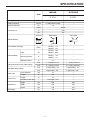
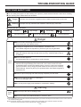
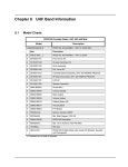
INDOOR
OUTDOOR
S 1731
S 1731
Unit
Cooling Capacity
BTU/h
9,000(4,400-10,600)
–
Heating Capacity
BTU/h
11,000(4,800-12,300)
–
Moisture Removal
L/h
1.6
–
phase
Single
V
230
Hz
50
Power source
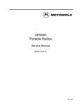
SIDE VIEW
TOP VIEW
m/min
Cooling ; 7.8
Heating ; 8.6
–
Input
W
Cooling ; 760
Heating ; 860
–
Running Current
A
Cooling ; 3.6
Heating ; 4.1
–
Starting Current
A
4.1
–
inch
L ; Half Union 1/4''
L ; 2-way valve 1/4''
inch
G ; Half Union 3/8''
G ; 3-way valve 3/8''
inch
L (liquid side) ; 1/4''
L (liquid side) ; 1/4''
inch
G (gas side) ; 3/8''
G (gas side) ; 3/8''
OUTLET
Airflow Method
INTAKE
Air circulation (at High)
3
Electrical Data
Piping Connection Port (Flare piping)
Pipe Size (Flare piping)
Drain hose
Power Cord
Dimensions
Net Weight
mm
14
–
Length
m
0.6
–
Length
m
1.4
Inner diameter
–
2
Number of core-wire
core-wire/ 1 mm
–
Height
mm
265
530
Width
mm
795
780
Depth
mm
192
277
kg
7.8
30.0
–1–
SPECIFICATION
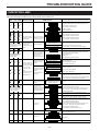
INDOOR
OUTDOOR
S 1731
S 1731
Cross-flow Fan
Propeller Fan
Induction (4-pole)
Induction (6-pole)
18
21
Unit
Type
Air Circulation
Motor Type
Rated Output
W
Plate fin configuration,forced draft
Heat Exchanger
18.1FPI
19.5FPI
–
Capillary Tube
–
850(30.0)
Electronic Control
–
Real time dual ON/OFF
7-hour OFF
–
Mold-proof
–
Refrigerant Control Device
Refrigerant (R410A )
g (oz)
Thermostat
Timer
Air Filter
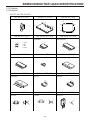
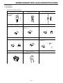
Parts Provided
1
2
3
4
5
6
7
8
Mounting plate
Remote controller
Battery (2 pcs.)
Remote controller holder
Screw cap (2 pcs.)
Drain elbow
Vibration proof rubber (4 pcs.)
Air clean filter×2
Bamboo Charcoal/Photo-catalytic anti-odor filter×1
Bio-photo Catalytic filter×1
9 Gum bushing
Specifications are subject to change without notice.
–2–
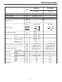
SPECIFICATION
INDOOR
OUTDOOR
S 1735
S 1735
Unit
Cooling Capacity
BTU/h
11,300(4,800-11,900)
–
Heating Capacity
BTU/h
12,500(4,800-14,300)
–
Moisture Removal
L/h
2.0
–
phase
Single
V
230
Hz
50
Power source
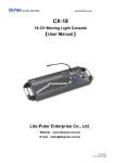
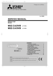
SIDE VIEW
OUTLET
Airflow Method
INTAKE
Air circulation (at High)
Cooling ;
Heating ;
3
m/min
Cooling ; 970
Heating ; 880
–
Running Current
A
Cooling ; 4.6
Heating ; 4.2
–
Starting Current
A
4.6
–
inch
L ; Half Union 1/4''
L ; 2-way valve 1/4''
inch
G ; Half Union 3/8''
G ; 3-way valve 3/8''
inch
L (liquid side) ; 1/4''
L (liquid side) ; 1/4''
inch
G (gas side) ; 3/8''
G (gas side) ; 3/8''
Pipe Size (Flare piping)
Dimensions
Net Weight
–
W
Piping Connection Port (Flare piping)
Power Cord
9.3
9.8
Input
Electrical Data
Drain hose
TOP VIEW
mm
14
–
Length
m
0.6
–
Length
m
1.4
Inner diameter
–
2
Number of core-wire
core-wire/ 1 mm
–
Height
mm
265
530
Width
mm
795
780
Depth
mm
199
277
kg
8.9
30.0
–3–
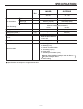
SPECIFICATION
INDOOR
OUTDOOR
S 1735
S 1735
Cross-flow Fan
Propeller Fan
Induction (4-pole)
Induction (6-pole)
22
21
Unit
Type
Air Circulation
Motor Type
Rated Output
W
Plate fin configuration,forced draft
Heat Exchanger
19.5FPI
19.5 FPI
–
Capillary Tube
–
850(30.0)
Electronic Control
–
Real time dual ON/OFF
7-hour OFF
–
Mold-proof
–
Refrigerant Control Device
Refrigerant (R410A )
g (oz)
Thermostat
Timer
Air Filter
Parts Provided
1
2
3
4
5
6
7
8
Mounting plate
Remote controller
Battery (2 pcs.)
Remote controller holder
Screw cap (2 pcs.)
Drain elbow
Vibration proof rubber (4 pcs.)
Air clean filter×2
Bamboo Charcoal/Photo-catalytic anti-odor filter×1
Bio-photo Catalytic filter×1
9 Gum bushing
Specifications are subject to change without notice.
–4–
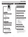
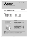
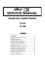
FUNCTIONS
REMOTE-CONTROL TRANSMITTER
INDOOR UNIT
Sensing the room temperature
Room temperature sensor (thermistor)
ON/OFF
Time delay safety control
Operation mode selection
Restarting is inhibited for approximately
3 minutes.
COOL
DRY
HEAT
AUTOMATIC
CIRCULATION
Indoor fan speed control
High, Med, Low
Operation indication lamps (LED)
Air flow selection
POWER
AUTOMATIC
HIGH
MEDIUM
LOW
(GREEN or RED)
Lights up green during operation.
Lights up red when negative ions are
generated.
TIMER (YELLOW)
Timer in operation
OPERATE (GREEN)
Outdoor unit operate
Negative Ion
Room temperature setting
16°C ∼ 30°C
Dry operation mode
Timer operation selection
Automatic fan speed control
CONTINUOUS operation
OFF
ON
Sleep
Room temperature control
Maintains the room temperature in
accordance with the setting temperature.
Timer / time setting
Deice (defrost) control
Operation stops at the set time
(OFF timer)
Operation starts at the set time
(ON timer)
0.5 ∼ 7.0hours(Sleep timer)
Deicing operation automatically starts
when the heating efficiency is declined by
the ice formed in the outdoor unit.
After deicing operation, heating operation
automatically starts with “Hot start
function.”
Air flow direction control
Auto angle selection
Auto swing mode
Manual mode
INDOOR UNIT
–5–
FUNCTIONS
OUTDOOR UNIT
Hot-start control (heating)
The indoor fan stops until the evaporator
piping temperature will be reached.
Anti-freezing control for the
evaporator
Compressor will be stopped when the
evapolator’s piping temperature is below
2℃ for one minute.
Compressor will be restarted when the
evaporator’s piping temperature is above
2℃.
Airflow direction control
Inverter control
When ON/OFF BUTTON is pressed, the
vertical louver will move to the adequate
positions for each operation automatically.
Manual operation.
The louver starts vertical swing with a
push of the LOUVER BUTTON.
Push the LOUVER BUTTON once again
to stop the louver at the desired position
while swinging.
Inverter control reduce the ON/OFF
times of compressor,so can keep the
room temperature changeless during
operation.
Electricity consumption
Inverter control can operate with less
electricity consumption than normal air
conditioner.
Auto recovery function
If there is any power failure during
operation, operation status before power
failure is memorized.
3 ∼ 4 minutes after power recovery, the
unit restarts automatically with previous
operation status memorized.
(3 ∼ 4 minutes is protective time for
compressor.)
3 min. forced operation control
Once the compressor is activated, it
does not stop for 3 minutes.
In case of termination of this operation,
push the ON/OFF button on remote
controller.
Attention
Because of Auto recovery function, if
shutting off the power supply during
operation, the unit may restart
irrespective your intention when turning
on the power supply next time.
If the unit is not to be used for a long
time, shut off the power supply after
terminating all operation with remote
controller.
–6–
SERVICE FUNCTION EXPLANATION
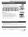
EMERGENCY AND TEST OPERATION
Emergency Operation
•
•
•
•
Use this operation only when the remote controller is out of order or lost.
When the emergency operation switch is pressed, beep starts once, which
means the start of this operation.
In this operation, the system automatically selects the operation modes, cooling
(or heating when available) according to the room temperature, as follows.
Temperature
Operation
mode
Designated
temperature
Timer mode
Air flow
ABOVE 23℃
COOLING
26℃
CONTINUOUS
AUTOMATIC
BELOW 23℃
HEATING
23℃
CONTINUOUS
AUTOMATIC
It is not possible to operate in dry mode.
Beep
Twice beep
Test Operation
Test operation switch is same as emergency one.
• Use this operation only for testing the performance of the machine in
the condition where the room temperature is less than 16°C.
• Continue to press the test operation switch for more than 5 seconds.
After you hear twice beep, release your finger from the switch
: the cooling operation starts with the air flow speed “HI.”
• If the test operation switch is pressed more than 10 seconds, it doesn’t
work.
• After 30 minutes, test operation ends automatically.
HOW TO RELEASE EMERGENCY AND TEST OPERATION
•
•
In case of releasing during those operations, you can either push emergency operation switch once more or
apply operation using remote control.
You will hear a beep sound and emergency/ test operation is released.
If you release the operation by remote control, operation will continue as setting of the remote control
automatically.
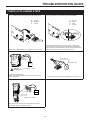
INTERFERENCE PREVENTION OF SIGNALS FROM THE REMOTE CONTROLLER
When two indoor units used in the same room, interference of the signals may happen. To avoid this, alternative
signal model B can be selected by the following. (Ex-factory setting is mode A)
J1
J1
• Remote controller side
: Have “J1” on the PC board short-circuited by soldering.
• Indoor unit side
: Cut “R13” on the PC board.
Soldering
–7–
OPERATION DETAILS
TIMER OPERATION
ON Timer operation
• Press the ON/OFF switch. Right after replacing new batteries, set the present time in advance.
• Set the “ON Time” : Press the “TIME ADJ” button twice.
Adjust the time with the “ ,
” button.
Press the “TIME ADJ” button twice.The setting of “ON Time” is completed and the present time appears on the LCD.
• Set the “ON Timer” : Press the Timer fixing button “ON”.
OFF Timer operation
• Press the ON/OFF switch. Right after replacing new batteries, set the present time in advance.
• Set the “OFF Time” : Press the “TIME ADJ” button 3 times.
Adjust the time with the “ ,
” button.
Press the “TIME ADJ” button once.The setting of “OFF Time” is completed and the present time appears on the LCD.
• Set the “OFF Timer” : Press the Timer fixing button “OFF”.
Sleep Timer operation
• Press the “SLEEP” button during the operation.
• Set the operating period by pressing the “SLEEP” button until the period designated appears on the LCD.
Timer Cancellation
• ON/OFF Timer : Press the Timer fixing button “ON”(On Timer) and/or “OFF”(Off Timer) once again.
• Sleep Timer : Press the “SLEEP” button until the operating period on the LCD disappears.
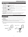
AIRFLOW DIRECTION CONTROL
Vertical adjustment
When ON/OFF switch is pressed, the vertical louver will move to the adequate positions for each operation
automatically.
Swing of air flow
If air flow direction switch is pressed once, the vertical louver will move within the range of figures.
Fixing the flow direction
If air flow direction switch is pressed again, the vertical louver will be fixed and that position is memorized.
From the next operation the louver will be set at previous position automatically.
Notes :
• In Swing Mode, the louver automatically moves up and down within the certain range, as the illustration below.
• There is two different ranges of louver swinging; one is of cooling & dry mode operation and the other is of
heating operation.
Standard Position
Swing of Air Flow
Level
Level
Approx.10 degrees
(Cooling/Dry)
Approx.10
degrees
Approx.65 degrees
(Heating)
Cooling
Dry
Heating
Approx.50
degrees Approx.65
degrees
–8–
OPERATION DETAILS
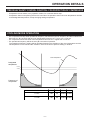
TIME DELAY SAFETY CONTROL FUNCTION - FOR PROTECTION OF COMPRESSOR
•
•
Compressor will not restart, in any operation modes, for 3 minutes after its stop.
Compressor does not stop during the first ★ 1 seconds of its operation even if the room temperature reaches
to the designated temperature, except changing setting temperature.
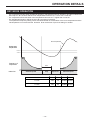
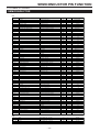
COOLING MODE OPERATION
•
•
•
The compressor will stop when operational frequency reached the minimum frequency and that condition has
been kept for ★ 1 seconds and the room temperature becomes 1.3℃ lower than it was set.
The compressor will re-start when room temperature becomes 0.7℃ higher than it was set.
The operational frequency will be set every ★ 2 seconds of operation.
The operational frequency setting will be calculated based on the deviation of the room temperature and the
set temperature on one end and the deviation factor at the time of previous setting on another.
Room temperature
Designated
temperature
0.7˚C
-1.3˚C
MAX
★3
MAX
★3
Frequency of
compressor
0
MIN★4
MIN★4
Hz
Model
★1
★2
S 1731
120
40
68.0Hz 32.0Hz
S 1735
180
60
72.0Hz 32.0Hz
–9–
★3
★4
OPERATION DETAILS
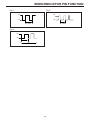
DRY MODE OPERATION
•
•
•
The compressor will stop when operational frequency reached the minimum frequency and that condition has
been kept for ★ 1 seconds and the room temperature becomes 1.3℃ lower than it was set.
The compressor will re-start when room temperature becomes 0.7℃ higher than it was set.
The operational frequency will be set every ★ 2 seconds of operation.
The operational frequency setting will be calculated based on the deviation of the room temperature and the
set temperature on one end and the deviation factor at the time of previous setting on another.
Room temperature
Designated
temperature
0.7˚C
-1.3˚C
MAX
★3
MAX
★3
Frequency of
compressor
3min.
0
Indoor fan
Hz
MIN★4
Selected speed
MIN★4
Stop
Super low
Selected speed
Model
★1
★2
S 1731
120
40
68.0Hz 32.0Hz
S 1735
180
60
72.0Hz 32.0Hz
– 10 –
★3
★4
OPERATION DETAILS
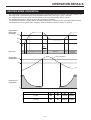
HEATING MODE OPERATION
•
•
•
The compressor will stop when operational frequency reached the minimum frequency and that condition has
been kept for ★ 1 seconds and the room temperature becomes 5.0°C higher than it was set.
The compressor will re-start when room temperature becomes 3.0°C higher than it was set.
The operational frequency will be set every ★ 2 seconds of operation.
The operational frequency setting will be calculated based on the deviation of the room temperature and the
set temperature on one end and the deviation factor at the time of previous setting on another.
Temperature,
indoor heat
exchanger
33˚C
29˚C
15˚C
20sec.
Stop Super Low Designate Fan blow
low
Indoor fan
Low
Super low
Low
Designated
Fan blow
Room temperature
Designated
temperature +5.0
+3.0
MAX
★3
MAX
★3
Frequency of
compressor
0
MIN★4
MIN★4
Hz
Model
★1
★2
★3
★4
S 1731
120
40
74.0Hz
32.0Hz
S 1735
180
60
80.0Hz
32.0Hz
– 11 –
OPERATION DETAILS
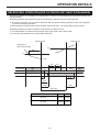
DEFROSTING OPERATION(FOR OUTDOOR UNIT HEAT EXCHANGER)
•
•
•
Defrosting operation is controlled by the temperature of outdoor heat exchanger sensed by the thermistor and
the timer switch.
Defrosting operation starts when the both of the following conditions are met at the same time.
a) 34 minutes’ of continuous run of the compressor after the start of heating operation or after the completion
of previous defrosting operation.
b) the temperature of the outdoor heat exchanger stays lower than -1°C continuously for two minutes.
Defrosting operating is called off if either of the following conditions is met.
a) The temperature of outdoor heat exchanger rises to 8°C while 4-way-valve is ON.
b) 12 minutes has passed since compressor turned OFF.
Defrosting starts
Defrosting stop
Temperature of
outdoor heat exchanger
8˚C
2min.
-1˚C
Compressor
ON
Outdoor fan
ON
OFF
2min.
1min.
48.0Hz
★1
★2
OFF
ON
ON
4way valve
ON
10
sec.
50sec.
50sec.
53sec.
53sec.
Max 12min.
★1
Model
★2
S 1731
58.0Hz 74.0Hz
S 1735
58.0Hz 80.0Hz
– 12 –
OPERATION DETAILS
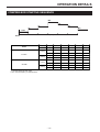
COMPRESSOR STARTING SEQUENCE
Max
F4
F3
F5
F2
Min
10Hz
T1
T2
T3
T(Max)
T4
T5
Start
Model
Frequency
F2
F3
Max
F4
F5
Min
Time
T2
T3
T(Max)
T4
T5
-
48Hz
58Hz
68Hz
-
54Hz
32Hz
1.5min.
1min.
30min.
-
limitless
-
48Hz
58Hz
74Hz
-
64.7Hz
32Hz
1.5min.
1min.
40min.
-
limitless
-
48Hz
58Hz
72Hz
-
66.7Hz
32Hz
1.5min.
1min.
30min.
-
limitless
-
48Hz
58Hz
80Hz
-
69.3Hz
32Hz
1.5min.
1min.
40min.
-
limitless
-
Cooling
S 1731
Heating
Cooling
S 1735
Heating
T1: Forced rotating to reach 10Hz
F2,F3: Forced frequency for lubricant back
– 13 –
TROUBLESHOOTING GUIDE
FOR YOUR SAFETY USE
IN: indoor unit
OUT: outdoor unit
● For the safety and proper use and handling of the product, please read and follow the instructions carefully.
● The meaning of the marks below are as follows.
Danger
Improper use will cause the significant risk of death or serious injury of the user.
Warning
Improper use may cause the risk of death or serious injury of the user.
● Please refer the marks below.
Caution
Strict enforcement
High Voltage
Off the Plug
Connect the earthing cable
Prohibited
High Temperatare
Danger
● Be sure to take off the plug when servicing.
It may cause the risk of electric shock.
● If leakage of refrigerant occur in the installation, ventilate a room.
If the leaked refrigerant is exposed fire, poisonous gas may be generated.
● Boosting capacitor make the control box assembly (OUT unit) high voltage.
Make the capacitor discharge enough when servicing. Otherwise will be struck
by electricity.
● Never remodel appliance.
Use designated parts or accessories to avoid accidents.
Check
Point
● In case of gas leakage, not only refill the required amount of the refrigerant gas but
also find out the gas leakage point and mend it. If the service work has to be
suspended before mending the leakage points, be sure to collect the refrigerant
gas in the outdoor unit by using pump then fasten the service ports to avoid any
further leakage. Poisonous gas may be generated when the leaked refrigerant is
exposed to fire.
● Clean the pins of the plug and insert the plug completely into the outlet.
● Be sure to change the cable if it is damaged.
Do not use damaged cable.
● Do not use power supply cord extended or connected in halfway.
Warning
Check
Point
● Be sure to put the units to earthing works.
● Be sure to check the insulated resistance, more than 1M Ω .
※ The combinations of three LED indicators (ON/Flashing/OFF) provide the self-diagnosis information as most of them shown in
the trouble shooting guide.
[Note1] Discharge electricity of the capacitor by making short circuit firstly. Then check the capacitor by tester.
Be sure to set up the tester for the measurement of bigger resistance.
– 14 –
TROUBLESHOOTING GUIDE
INDICATION LAMP
Micro computer self-diagnose the points of the troubles and inform it by the combination of the status (On, Flush, or
Off) of three lamp indicators on the front panel of the indoor unit.
INDICATION LAMP
POWER
(green)
TIMER
(yellow)
OPERATION
(green)
ALARM
INDICATION TIME
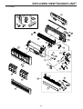
APPEARANCE, PORTION, PARTS
SEEMED WRONG
POWER SUPPLY
REMOTE CONTROL
OFF
OFF
OFF
-
-
check the plug inserted into the outlet and the power supply
emergency operation (display of remote controller is faint or not)
IN FUSE(3.15A)
check the electric continuity by tester
IN TERMINAL BLOCK
check the electric continuity by tester
PCB (RECEIVER & DISPLAY)
IN, OUT do not work at all
METHOD OF CHECK
(press the ON/OFF button of remote controller in case of reset)
IN PCB (MAIN)
emergency operation
other than described above
FLASHING
OFF
OFF
SENSOR, TEMP. ROOM
check the resistance by tester [see table 1]
FLASHING
ON
ON
SENSOR, TEMP. HEAT EXCHANGER
check the resistance by tester [see table 2]
ON
ON
FLASHING
SENSOR, TEMP. DEFROST
check the resistance by tester [see table 2]
ON
FLASHING
OFF
SENSOR, TEMP. OUTDOOR
check the resistance by tester [see table 2]
FLASHING
ON
OFF
SENSOR, TEMP. DISCHARGE
check the resistance by tester [see table 3]
OFF
OFF
FLASHING
IN, OUT don’t work at all,
and after 20 sec., operation
lamp is flashing (2 min. in
case of power on)
FLASHING
OFF
OFF
FLASHING
alarm indication appears
immediately when press
operation switch
normal lamp indication
turn alarm when
FLASHING
error of transmission
something is wrong with
CT disconnection
OFF
-
OFF
sensor discharge operate
because temperature of
discharge tube beyond
100°C, or sensor
discharge is bad quality
protective action against
excessive AC current
detection
power lamp lighting when
or
FLASHING
26 min.
later after that in case of
OFF
ON
check the electric continuity by tester.[see fig. 2]
(if it is no continuity, OUT controller assy should be replaced.)
CUTTING OFF CT
reoccurrence, alarm
indication appears
VALVE, SERVICE IS CLOSED
PIPE
protective action against
excessive DC current
detection
or
abnormal revolution of
compressor
FLASHING
FLASHING
FLASHING
FLASHING
FLASHING
in case of heating operation,
after a few minutes operation,
all lamps are flashing and
IN, OUT stop running
-
-
rise of temperature
(above 100°C) of power
module
in case of heating
operation, a rise of
temperature (above 62°C)
of IN heat exchanger or
less quantity of IN blow
-
ON
-
FLASHING
check the resistance by tester [see table 3]
check the place of installation (blockage of air inlet & outlet of IN, OUT)
check the excessive gas
MOMENTARY STOP OF POWER
(IN CASE OF LIGHTNING)
MOMENTARY STOP OF POWER
(IN CASE OF LIGHTNING)
DROP OF POWER VOLTAGE
OUT PCB (MAIN)
SHORT CYCLE
(INSUFFICIENT AIR CIRCULATION)
UNREASONABLE OPERATION
UNDER OVERLOAD
FILTER IS CHOKED
SENSOR, TEMP. HEAT EXCHANGER
IN PCB (MAIN)
FAN MOTOR (IN)
-
-
-
accident of controller
not cool down
not warm up
-
-
-
-
-
-
water leakage
nasty smell
-
-
-
louver doesn' t work
check the place of installation (blockage of air inlet & outlet of IN, OUT)
check the excessive gas
check the movement by reoperation
check the power voltage (230V)
If the same alarm lamp will remain lit during operation even after
disconnecting the connector of the lead cable to the compressor,
it implies the defect of the OUT controller assy.
If the same alarm lamp will remain lit during operation even after replacing
the OUT controller assy, it implies the defect of the compressor.
check the place of installation (blockage of air inlet & outlet of
IN, OUT)
check by eyes and clean it
check the resistance by tester [see table 2]
check the voltage between blue and yellow in connector [see fig.3]
if it is not AC 110V ∼ 230V, IN PCB (main) should be replaced
other than described above
15 sec. later after main power on, if alarm indication appears,
IN PCB (main) should be replaced
GAS LEAKAGE
check the point of leakage measure the pressure of compressor
during fixed operation (emergency and test operation)
SENSOR, TEMP. ROOM
check the resistance by tester [see table 1]
SENSOR, TEMP. HEAT EXCHANGER
check the resistance by tester [see table 2]
FAN MOTOR
(IN)
DRAINAGE
check the voltage between blue and yellow in connector [see fig.3]
if it is AC 110V ∼ 230V, IN fan motor should be replaced
check the resistance by tester [see fig.4]
check the blockage of air inlet & outlet of IN, OUT
check the drain hose by eyes (it might be folded or choked)
MIS-INSTALLATION
check the IN whether lean or not
FILTER IS CHOKED
check by eyes and clean it
NO USE FOR A LONG TIME
NASTY SMELL
(CIGARETTE, FURNITURE, ETC.)
-
check the power voltage (230V)
60 sec. later after start running through remote controller, if alarm
indication appears, OUT controller assy should be replaced
4-WAY VALVE
-
check the movement by reoperation
OUT PCB (MAIN)
SHORT CYCLE
(INSUFFICIENT AIR CIRCULATION)
-
check the valve by eyes
UNREASONABLE OPERATION
UNDER OVERLOAD
IN PCB (MAIN)
FLASHING
check the point of leakage (discharge temperature rise in case of
small leakage), measure the pressure of compressor during fixed
operation (emergency and test operation)
check by eyes
COMPRESSOR LOCKING
ON
change the OUT PCB (main)
SENSOR, TEMP. DISCHARGE
UNREASONABLE OPERATION
UNDER OVERLOAD
IN, OUT, and start
running again after 6 ∼
ON
CURRENT FUSE . (12A) FUSING
(ON THE OUT PCB (FILTER))
DROP OF POWER VOLTAGE
something is wrong with
FLASHING
check the wiring connection and rare contact
GAS LEAKAGE
once stop running with
FLASHING
MIS-WIRING
(OUT-IN CONNECTING CABLE)
OR RARE CONTACT
IN, OUT
FLASHING
30 ∼ 40 min. later after
compressor start, the yellow
lamp is flashing and IN,
OUT stop running
FLASHING
short or open of sensor,
temperature or incomplete
insertion of connector
LOUVER MOTOR
※In this table IN means indoor unit and OUT means outdoor unit.
– 15 –
use deodorizer
check the resistance by tester [see fig.5]
TROUBLESHOOTING GUIDE
CHECK A FOLLOWING STEPS
〔fig. 1〕Voltage of OUT fan motor on the OUT PCB( main)
〔fig. 2〕Continuity of current fuse on the OUT PCB(filter)
B : BLACK
BR : BROWN
W : WHITE
B
GR
R
W
W
R
B
GR
18
: BLACK
: GRAY
: RED
: WHITE
AC230V
10
W BR
B
AC230V
Measure the voltage between white and black in the connector.
〔fig. 3〕Voltage of IN fan motor on the IN PCB (main)
While the operation switch is turned on, the function of control board
is considered normal as long as the voltage difference shows AC230V
when the voltage is measured between the white and the black terminals,
and between the black and the grey terminals respectively.
〔fig.4〕Resistance of 4-way valve coil
blue
red
yellow
4-way valve coil
IN fan motor
connector
tester
1.5kΩ
Normal:1.5k1
voltage
attention
electric shock
Normal:110V ∼ 230V
《Check the IN PCB(main)》
Measure the voltage between the connector pins in the back
of IN PCB(main).
※ Take off the connector and check the Resistance of 4-way valve coil.
〔fig. 5〕Resistance of IN louver motor
(5)
(1)
tester
common terminal
resistance
terminal block
Normal:360 ∼ 3901
Take off the connector and check the resistance between
the common terminal and each terminal.
– 16 –
TROUBLESHOOTING GUIDE
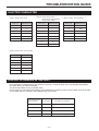
ELECTRIC CHARACTER
〔table 2〕Sensor, temp. defrost
Sensor, temp. heat exchanger
Sensor, temp. outdoor
〔table 1〕Sensor, temp. room
〔table 3〕Sensor, temp. discharge
Temp. (°C)
Resistance (k1)
Temp. (°C)
Resistance (k1)
Temp. (°C)
Resistance (k1)
10
48
0
31
10
1,130
15
37
5
24
20
660
20
29
10
19
35
320
25
23
15
15
40
250
30
18
20
12
50
160
35
15
25
10
80
50
30
8
35
7
〔table 4〕Sensor, temp. power module
Temp. (℃)
Resistance (k Ω )
10
210
30
79
50
33
70
15
90
8
110
4
DISPLAY OF ERRORS IN THE PAST
•
Push emergency operation switch and hold for more than 10 seconds while unit is not operated and release
the switch when you hear three beeps.
You will see the latest error by indication lamp.
Further pushing of the switch will make the error indication by reversing cycle up to four latest errors in the past.
At any stage, the error indication will disappear after 30 seconds.
Hold switch for more
than 10 seconds
Three beeps
Another push
Two beeps
The second latest error indication
Another push
Three beeps
The third latest error indication
Another push
Four beeps
The fourth error indication
Another push
One beep
Indication lamp goes off
– 17 –
The latest error indication
TROUBLESHOOTING GUIDE
WIRING DIAGRAM
S 1731 Indoor
S 1735 Indoor
BL
R
MOTOR(FAN)
BL
R
TRANSFORMER
BL R
Y
B
IONIZER
W
BR
PCB
(RECEIVER
&DISPLAY)
P
FUSE
(T3.15A)
S
B
MANUAL SWITCH
BL
SENSOR
(TEMP.,ROOM)
BL
BR
B
POWER
SOURCE
SENSOR
(TEMP.,HEAT
EXCHANGER)
B
PCB(MAIN)
R
W
MOTOR
(LOUVER)
BL
G/Y
EARTH
TERMINAL
TERMINAL
3 2 1 BLOCK
↓ OUTDOOR UNIT
S 1731 Outdoor
S 1735 Outdoor
COMPRESSOR
T
R
S
R
W
MOTOR
(FAN)
SENSOR
(TEMP.,
DISCHARGE)
SENSOR
(TEMP.,
DEFROST)
SENSOR
(TEMP.,
OUTDOOR)
4WAY V.
B
21
22
B
W
R
R
S
T
18
17
HEATER
20
MAIN P.C.B
FILTER P.C.B
W
12
B
1
10
R
13
4
GR
3
VOLTAGE
W
2
BL
Y/G
TAN : INDOOR UNIT
TAG : OUTDOOR UNIT
Y
REACTOR
– 18 –
1
2
3
INDOOR
UNIT
R
B
OR
TERMINAL
BLOCK
BL
B
BL
BR
G
GR
OR
P
R
W
Y
: BLACK
: BLUE
: BROWN
: GREEN
: GRAY
: ORANGE
: PINK
: RED
: WHITE
: YELLOW
PERFORMANCE CURVE DIAGRAM
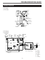
REMARKS FOR GAS PRESSURE CHECK AND CHARGING
Gas pressure is to be measured at TEST OPERATION for cooling or EMERGENCY OPERATION for
heating. (It is operated for 30 minutes at fixed frequency.)
If you find substantial diffrence in performance compared with PERFORMANCE CURVE as shown next,
recharge the refrigerant.
(In order to avoid excessive charging, purge all the remaining refrigerant first and then evacuate the unit
completely with vacuum pump and finally apply rated volume charging of refrigerant.)
Charging of refrigerant should be done by cooling operation, because the pressure at service valve will
be too high at heating cycle, then the heating performance characteristics must be checked by restarting
of heating operation.
Liquid side
6.35mm
Gas side
9.52mm
Piping size
Max. tube length
15m
Max. height difference
10m
– 19 –
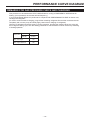
PERFORMANCE CURVE DIAGRAM
S 1731
COOLING
(A)
5.0
4.5
4.0
CURRENT
3.5
3.0
2.5
2.0
(°C)
30
25
TEMPERATURE
BLOW OUT
20
15
10
5
0
(MPa)
1.5
1.3
SERVICE PORT
PRESSURE
1.1
0.9
0.7
0.5
20
25
30
35
(°C)
HUMIDITY60%
AIR TEMPERATURE INDOOR-OUTDOOR
HEATING
(A)
AIR-TEMPERATURE
INDOOR 20°C
5.0
4.5
CURRENT
4.0
3.5
3.0
(°C)
50
45
TEMPERATURE
BLOW OUT
40
35
(MPa)
3.5
SERVICE PORT
PRESSURE
3.0
2.5
2.0
5
10
15
20
(°C)
HUMIDITY50%
AIR TEMPERATURE-OUTDOOR
– 20 –
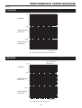
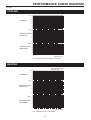
PERFORMANCE CURVE DIAGRAM
S 1735
COOLING
(A)
5.0
4.5
4.0
CURRENT
3.5
3.0
2.5
2.0
(°C)
30
25
TEMPERATURE
BLOW OUT
20
15
10
5
0
(MPa)
1.2
1.1
SERVICE PORT
PRESSURE
1.0
0.9
0.8
0.7
20
25
30
35
(°C)
HUMIDITY60%
AIR TEMPERATURE INDOOR-OUTDOOR
HEATING
(A)
AIR-TEMPERATURE
INDOOR 20°C
5.5
5.0
CURRENT
4.5
4.0
3.5
(°C)
TEMPERATURE
BLOW OUT
50
45
40
35
(MPa)
3.5
SERVICE PORT
PRESSURE
3.0
2.5
2.0
5
10
15
20
(°C)
HUMIDITY50%
AIR TEMPERATURE-OUTDOOR
– 21 –
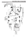
ELECTRIC CIRCUIT DIAGRAM
S 1731 Indoor, S 1735 Indoor
INDOOR
FAN MOTOR
IONIZER
YELLOW
RED
BLUE
1
3
CN7
C1
C3
L1
C2
ZE1
BLACK
WHITE
BROWN
1 3 5 CN4
RL2A
CF1
RL1A
PC2B
1 2 3
CN9
THERMISTOR
(EVA)
THERMISTOR
(ROOM)
1
2
3
CN8
4
5
6
7
1
2
3
4
5
6
7
CN1
LOUVER MOTOR
RECEIVER UNIT
OPERATE LED
TIMER LED
ELECT LED
IONIZER LED
PCB(RECEIVER & DISPLAY)
PCB(MAIN CONTROLLER)
IC1
1
2
CN12 3
4
5
MANUAL SW
1 2 3 4
CN11
RL1B RL2B
PC3B
CN6
S
BLUE
1 3
P
RED
BLUE
PC1A PC2A
CN1 1 3
RED
TRANSFORMER
WIRELESS
REMOTE
CONTROL
– 22 –
250V T3.15A
PC1B
PC3A
R2
R3
(INDOOR UNIT)
C11
RL1TAB1
RL1TAB2
BLACK
CN2
WHITE
1
D1
2
RED
R21
AC CORD
TERMINAL
BLOCK
1
2
3
BLACK
WHITE
RED
GREEN/
YELLOW
TERMINAL
BLOCK
1
2
3
(TO OUTDOOR UNIT)
D2
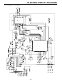
ELECTRIC CIRCUIT DIAGRAM
S 1731 Outdoor , S 1735 Outdoor
– 23 –
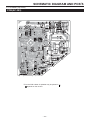
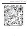
SCHEMATIC DIAGRAM AND PCB’S
S 1731 Indoor (Top View)
PCB(AC-383)
※
※
※ On the PCB a letter of alphabet may be printed in
depends on the version.
– 24 –
.
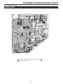
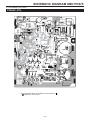
SCHEMATIC DIAGRAM AND PCB’S
S 1735 Indoor (Top View)
PCB(AC-382)
※
※
※ On the PCB a letter of alphabet may be printed in
depends on the version.
– 25 –
.
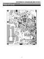
SCHEMATIC DIAGRAM AND PCB’S
S 1731 Outdoor (Top View)
PCB(AC-377)
※
※ On the PCB a letter of alphabet may be printed in
depends on the version.
– 26 –
.
SCHEMATIC DIAGRAM AND PCB’S
S 1735 Outdoor (Top View)
PCB(AC-379)
※
※ On the PCB a letter of alphabet may be printed in
depends on the version.
– 27 –
.
SCHEMATIC DIAGRAM AND PCB’S
S 1731 Outdoor, S 1735 Outdoor
FILTER PCB(AC-378)
※
※ On the PCB a letter of alphabet may be printed in
depends on the version.
– 28 –
.
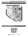
SCHEMATIC DIAGRAM AND PCB’S
S 1731 Indoor, S 1735 Indoor (Bottom View)
PCB(AC-383, AC-382)
S 1731 Indoor, S 1735 Indoor
PCB RECEIVER & DISPLAY(AC-359)
※
※ On the PCB a letter of alphabet may be printed in
depends on the version.
– 29 –
.
SCHEMATIC DIAGRAM AND PCB’S
S 1731 Outdoor, S 1735 Outdoor (Bottom View)
PCB(AC-377, AC-379)
– 30 –
SCHEMATIC DIAGRAM AND PCB’S
S 1731 Outdoor, S 1735 Outdoor (Bottom View)
FILTER PCB(AC-378)
– 31 –
SCHEMATIC DIAGRAM AND PCB’S
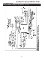
S 1731 Indoor, S 1735 Indoor
SCHEMATIC DIAGRAM(AC-383, AC-382, AC-359)
– 32 –
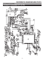
SCHEMATIC DIAGRAM AND PCB’S
S 1731 Outdoor, S 1735 Outdoor
SCHEMATIC DIAGRAM(AC-377, AC-379)
– 33 –
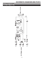
SCHEMATIC DIAGRAM AND PCB’S
S 1731 Outdoor, S 1735 Outdoor
FILTER PCB(AC-378)
– 34 –
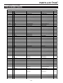
PARTS LIST (PCB)
S 1731 Indoor, S 1735 Indoor
PCB ASSEMBLY(MAIN)
AC-382,383
ALTERNATIVE
REF. No.
PB1
PB1
IC1
PART NAME
PCB
PCB
Micro Proccer
Q'TY
1
1
1
Bridge Diode
Innductor
Ceramic Resonator
Buzzer
Varistor
Connector
Connector
Connector
Connector
Connector
Connector
Connector
Connector
Connector
Current Fuse
Fuse Crip
Tact Switch
Relay
Relay
Film Capacitor
Film Capacitor
Film Capacitor
Electrolytic Capacitor
Electrolytic Capacitor
Ceramic Capacitor
Ceramic Capacitor
PART NUMBER
CE-374 C0 for A C-382
CE-374D0 for A C-383
M38039FFFP
M38037M8H-201KP
S-93L C56ADFJ-TB- S
BR93LC56RF-WE2
M63823 GP-200D
XC61 CN4202NR
TLP371
S201DH1Y
PC357N9
DT C143XKAT146
DTA114EKAT146
AN78L05-TA
NJM78L05A-T3
S1ZB60-4072
SN8D-500
CS TLA10M0T55-A0
PKM13EPY-4000-A0
TNR10V471K-T8
5271-03A
5289-2A
1-1123724-3
B3B-XH-TV4
1-1123724-2
B7B-PH-K- S
0-177538-3
S4B-XH- A
S5B-PH-K- S
2183.15M
TP00351-51
SKHHL Q179 A
G4A-1A-E D C12V
G5NB-1A4- SP D C12V
DS441125TL-B
ECQU2A224M GA
630MMW103KEFTL-B
25MV1000H C+T0
TC04R SM10VB100M F
MCH185 C102KK
MCH185 CN103KK
IC2
EEPR OM
IC3
IC4
PC1
PC2
PC3
DQ11,12,13,14
DQ15,16
RG1
Transistor Array
Low Voltage Detector
Photo Coupler
Solid State Relay
Photo Coupler
Transistor
Transistor
Voltage Regulator
DB1
L1
CX1
BZ1
ZE1
CN1
CN2
CN4
CN6
CN7
CN8
CN9
CN11
CN12
CF1
FC1,2
SW1
RL1
RL2
C1
C2
C3,4
C5
C6
C12,14,15,24,31
C11,18,21,22,23
C13 ,16 ,17 ,19 ,20 ,25
, 26,27,28,29,30
D1,2,3
Ceramic Capacitor
GRM188F11E104ZA0 1
11
Diode
Carbon Film Resistor
( Flame retardant
Carbon Film Resistor
(Flame retardant
Carbon Film Resistor
Carbon Film Resistor
Carbon Film Resistor
Carbon Film Resistor
Carbon Film Resistor
Car b on Fil m Res istor
DSK10E-BT
3
CFPS1/2CT26A101J
1
CFPS1/2CT26A103J
2
RD25 ST26J332
RD25 ST26J471
RD25 ST26J271
RD25 ST26J331
SR25TR102J
SR25TR103J
1
5
2
1
7
1
OR
OR
!
!
!
OR
!
!
!
!
!
!
!
!
!
!
!
!
!
R1
!
R2,3
R4
R5
R6,8
R7
R9,10,11,12,13,15,1
R14
– 35 –
1
1
1
1
1
1
4
2
1
1
1
1
1
1
1
1
1
1
1
1
1
1
1
1
2
1
1
1
1
1
2
1
1
5
5
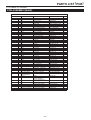
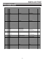
PARTS LIST (PCB)
S 1731 Indoor, S 1735 Indoor
PCB ASSEMBLY(MAIN)
AC-382,383
ALTERNATIVE
REF. No.
R21 ,30 ,4 0,5 1,5 2
R22
R23
R24,28,29,34,36,37,
38 ,41 ,54
R25
R26 ,4 2,4 9
R27
R31
R32
R33
R35
R39 ,4 6
R4 3,44
R45,47,4 8
R5 0
R5 3
J31 ,32 ,33 ,34 ,35 ,36 ,
J1 ,2,3,4,5,6,7,8,9,
10,11,12,13,14,15,
16,17,18,19,20,21,
22,23,24,25
PART NAME
Flat Chip Resistor
Flat Chip Resistor
Flat Chip Resistor
PART NUMBER
RP C0 5T 102 J
RP C0 5T 10 5J
M CR18 EZHJ47 2
Flat Chip Resistor
RPC05T103J
9
Flat Chip Resistor
Flat Chip Resistor
Flat Chip Resistor
Flat Chip Resistor
Flat Chip Resistor
Flat Chip Resistor
Flat Chip Resistor
Flat Chip Resistor
Flat Chip Resistor
Flat Chip Resistor
Flat Chip Resistor
Flat Chip Resistor
Flat Chi p Resistor
M CR18 EZHJ 222
RP C0 5T 332 J
RP C0 5T 682 J
M CR18 EZHJ 153
RP C0 5T47 1J
RP C0 5T 223 J
M CR18 EZHJ 101
RP C0 5T47 2J
M CR18 EZHJ 331
RP C0 5T 10 4J
M CR18 EZHF 3301
M CR03 EZHF 2002
MCR18EZZHJ000
1
3
1
1
1
1
1
2
2
3
1
1
8
Jumpere Wire
Q'TY
5
1
1
25
– 36 –
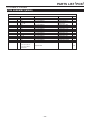
PARTS LIST (PCB)
S 1731 Indoor, S 1735 Indoor
PCB ASSEMBLY(RECEIVER&DISPLAY)
AC-359
ALTERNATIVE
ZP1
REF. No.
PART NAME
PART NUMBER
PB1
LD1
LD2
LD3
PD1
LS1
PCB
LED
LED
LED
Remote Receiver Unit
Lead Wire
LED Holder
CE-38100
SPR-39MVWF
SLR-342YY3F(L,M,N)
SLR-342MG3F(N,P)
SBX1810-52P
40002140
40002330
– 37 –
Q'TY
1
1
1
1
1
1
1
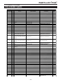
PARTS LIST (PCB)
S 1731 Outdoor, S 1735 Outdoor
PCB ASSEMBLY(MAIN)
AC-377, AC-379
ALTERNATIVE
OR
OR
Ref. No.
PARTS NAME
PARTS No.
Q'TY
PCB
CE-38700 for AC-377
1
PCB
CE-38710 for AC-379
1
C1
Film Cap.
ECQE2A103D69
1
C10,11
Electrolytic Cap.
25ME47AX+T
2
C105,106,107,108
Ceramic Cap.
GRM188B11H331KA01D
4
C12,16
Electrolytic Cap.
TC04RKY35VB220MH15F50E0
2
C13
Electrolytic Cap.
ESMG500ETC470MF11D
1
C14
Electrolytic Cap.
25ME100HC+T
1
C15,25
Electrolytic Cap.
ELXZ350ETD471MJ20S
2
C17
Electrolytic Cap.
ESMG100ETC101ME11D
1
C18
Electrolytic Cap.
10YK220MTA
1
C19,20,21
Electrolytic Cap.
TC04RKY25VB100MF11F50E0
3
C2
Electrolytic Cap.
UVR2E220MHD1TO
1
C22,23,24
Ceramic Cap.
UP050F104Z-A-BZ
3
C3
Film Cap.
UP45B125U2692A
1
C3
Film Cap.
DS441125TL-B
1
C31,32,66,67,68,70,71,73,77,82,
Ceramic Cap.
83,84,85,86,87,89,97,98,99
GRM188B11H102KA01D
19
C33,35,36,38,39,40,41,42,54,55,
57,60,65,72,76,88,92,93,94,95, Ceramic Cap.
100,102
GRM188F11E104ZA01D
22
C33,35,36,38,39,40,41,42,54,55,
57,60,65,72,76,88,92,93,94,95, Ceramic Cap.
100,102
MCH182CN104KK
22
C34,37,91
Ceramic Cap.
GRM188F11H473ZA01D
3
C4,5
Electrolytic Cap.
LLQ2G561KEUAZ0
2
C47,48,49,58,59,61,62,63,64,69,
Ceramic Cap.
75,96,101
MCH185CN103KK
13
C6,7
Film Cap.
ECQ-E6104KFA
2
C8
Film Cap.
630MMW103KEFTL-B
1
C9
Ceramic Cap.
DE2E3KH102MN3A
1
C90
Ceramic Cap.
GRM188B11H472KA01D
1
CF1
Current Fuse
250VLCR15AF916
1
CF2
Current Fuse
250VSCR3AF307
1
CN10
Connector
B04P-VL-VN-1.8
1
CN17
Connector
B02P-XL-HDB(LF)(SN)
1
CN18
Connector
1376383-1
1
CN19
Connector
1376382-1
1
CN20
Connector
BH3B-XH-2(LF)(SN)
1
CN21
Connector
BH2B-XH-2(LF)(SN)
1
CN22
Connector
BH3B-XH-2-Y(LF)(SN)
1
CN25
Connector
B6B-XH-A-Y(LF)(SN)
1
CT1
Current Transformer
CTN-EE1908CF
1
CX1
Ceramic Resonator
CSTLF14M7X53-A0
1
D1,2,3,4
Diode
1JU41(TPA3,Q)
4
D31,32,33,34
Diode
S1J-E3/11T
4
D35,36,37,38
Diode
D1FL20U-5063
4
D39,40,41,44
Diode
1SS355TE-17
4
D42
Diode
DAP202KT146
1
D43
Diode
DAN202KT146
1
– 38 –
PARTS LIST (PCB)
S 1731 Outdoor, S 1735 Outdoor
PCB ASSEMBLY(MAIN)
AC-377, AC-379
OR
OR
D45,46
Diode
RB751V-40TE-17
2
DB1
Bridge Diode
D15XB60-7009F13
1
DB2
Bridge Diode
D15XB60-7001
1
DQ33,34,35
Transistor(BRT Type)
DTC143XUAT106
3
DQ36,38
Transistor(BRT Type)
DTA114EUAT106
2
HS1
Heat Sink
OSH-1625-WFL
1
IC1
Switching Power IC
MIP0222SY
1
IC10
Logic IC
TC7W00F(TE12L,F)
1
IC11
Comparator IC
uPC339G2-E1-A
1
IC12
Shunt Regulator
uPC1093T-E1-AZ
1
IC12
Shunt Regulator
TA76431F(TE12L,F)
1
IC2
Power Module
FSBS15CH60
1
IC3
Micro Processor
TMP88CS43FG-6FC7
1
IC4
Low Voltage Detector
XC61CN4202NR
1
IC5
EEPROM
S-93C76ADFJ-TB-G
1
IC6
Transistor Array
M63823GP-DB0J
1
IC9
Logic IC
HD74HC367FP-EL-E
1
IC9
Logic IC
TC74VHC367F(EL,F)
1
J31
Jumpere Wire
MCR18EZHJ000
1
J32,33
Jumpere Wire
RPC05T0R0
2
L1,2
Inductor
LHLC06TB100K
2
L3
Inductor
LAL03TA220K
1
LS12
Lead Wire
40009110
1
LS13
Lead Wire
40009120
1
LS14
Lead Wire
40009130
1
LS15
Lead Wire
40009140
1
LS16
Lead Wire
40010640
1
PC1
Optocouplers
TLP371(F)
1
PC2
Optocouplers
TLP251(F)
1
PC31
Optocouplers
PS2705-1-V-F3-A
1
PC32,33
Optocouplers
PS2701-1-V-F3-A(L)
2
Q1
IGBT
GT30J121(Q)
1
R1,2,3
Flame Retardant Carbon Film Res.
CFPS1/2CT26A100J
3
R11
Chip Res.
RVC63474JTE
1
Chip Res.
RPC05T472J
14
R12,14
Chip Res.
RPC1ST393J
2
R13,21
Chip Res.
RPC05T105J
2
R130,131,132
Chip Res.
RPC18T330J
3
R139
Chip Res.
RPC18T102J
1
R141
Chip Res.
RPC05T822F
1
R15,16,17,18
Chip Res.
RPC1ST223J
4
Chip Res.
RK73H2BTTD1803D
Chip Res.
MCR50JZHJ104
Chip Res.
RPC05T102J
40
R23
Chip Res.
RPC1ST222J
1
R24,25,26,27
Chip Res.
MCR50JZHJ184
4
R28,48
Chip Res.
RK73B2ATTD471J
2
R19,20
– 39 –
14
2
PARTS LIST (PCB)
S 1731 Outdoor, S 1735 Outdoor
PCB ASSEMBLY(MAIN)
AC-377, AC-379
OR
OR
R29,33,36,39
Chip Res.
MCR10EZHJ103
4
R30,40,41,46,47,73,99,169
Chip Res.
RPC05T223J
8
R31,32
Chip Res.
RPC1ST473J
2
R34
Chip Res.
RK73B2ATTD100J
1
R35
Chip Res.
RK73B2ATTD680J
1
R37
Chip Res.
MCR50JZHJ471
1
R4
Cement Res.
BPR58CF20LJ
1
R42,89,90,95,96,100,102
Chip Res.
RPC05T103J
7
R43
Chip Res.
RPC05T184J
1
R44,74,75,147,149,151,152
Chip Res.
RPC05T103F
7
R45
Chip Res.
RPC05T222F
1
R49
Chip Res.
MCR10EZHF5600
1
R5,6
Flame Retardant Carbon Film Res.
CFPS1/2CT26A5R6J
2
R50
Chip Res.
RPC05T152J
1
R51,52,79
Chip Res.
RPC05T562J
3
R57
Chip Res.
RPC18T152J
1
R60,61,63,65,81,83,85,87
Chip Res.
MCR03EZPFX5601
8
R67,129
Chip Res.
RPC05T473F
2
R68,70
Chip Res.
MCR03EZPFX2002
2
R91,92,93,134,135
Chip Res.
RPC05T101J
5
R98
Chip Res.
RPC05T471J
1
RG1
Voltage Regulator
NJM78M15FA
1
RG1
Voltage Regulator
TA78M15S(Q)
1
RG1
Voltage Regulator
uPC78M15AHF-AZ
1
RG2
Voltage Regulator
TA78L005AP(TPE6,F)
1
RL1,2,3
Relay
G5NB-1A4-SP DC12V
3
OR
RL1,2,3
Relay
ALD112-J
3
OR
RL1,2,3
Relay
FTR-F3AA012E-KS
3
RL4
Relay
G4A-1A-E DC12V
1
T1
Switching Transformer
TAEM30M
1
TH1
PTC
ZPM0RCH330A250
1
TH31
Thermistor
NCP18WF104J03RB
1
VR1
Cermet Trimmer
FT-63ETV100ɉ(101)
1
ZD31,32
Zener Diode
U1ZB30(TE12R,Q)
2
ZE1
Varistor
TND10V-621KTFBAAA0
1
ZE2
Varistor
TND10SE471KTFBAAA0
1
Housing
XHP-6
1
TAB Cap
STC-250
1
Screw
M3x12
1
Adhesive
SC901
2
1
Silicone
YG6111
Coating Material
TF-1141T
10
Coating Material
LSS-520
10
– 40 –
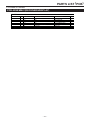
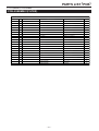
PARTS LIST (PCB)
S 1731 Outdoor, S 1735 Outdoor
PCB ASSEMBLY(FILTER)
AC-378
ALTERNATIVE
Ref. No.
PARTS NAME
PARTS No.
Q'TY
PCB
CE-38800
1
C1,3
Film Cap.
ECQU2A105MLA
2
C4,5,6,7,11
Ceramic Cap.
DE2E3KH472MN3A
5
1
CF1
Current Fuse
CES15-12A F021
D1,6
Diode
S1J-E3/11T
2
J11
Jumpere Wire
MCR18EZHJ000
1
1
L1
Line Filter
ADR25K-15010T
L2
Line Filter
ADR-25-10-030T-01
1
LS1
Lead Wire
40009060
1
LS2
Lead Wire
40009070
1
LS3
Lead Wire
40009080
1
LS4
Lead Wire
40009090
1
1
LS5
Lead Wire
40009100
R1
Flame Retardant Carbon Film Res.
CFPS1/2CT26A222J
1
R11,12,13,14
Chip Res.
MCR50JZHJ224
4
R17
Chip Res.
RPC1ST222J
1
SA1
Surge Absorber
EM2500X6SB2
1
ZE1,2,3
Varistor
TND10SE471KTFBAAA0
3
Cable Tie
T30R-HR(L152)
1
Coating Material
TF-1141T
5
Coating Material
LSS-520
5
– 41 –
SEMICONDUCTOR LEAD IDENTIFICATION
S 1731 Indoor
S 1735 Indoor
AC-359, AC-382, AC-383
IC1
IC3
M38037M8H-201KP
48
M63823GP
64
1
32
16
9
8
5
17
1
8
1
4
16
IC4
RG1
XC61CN4202NR
1
2
3
4
3
P2
1
S-93LC56ADFJ
33
49
4
IC2
2
S201DH1Y
TA78L05
NJM78L05
67
OUT
IN
NC
VSS
23
O
G
15
I
DQ11∼16
PC3
PC357N9
4
PC2
1
DSK10E
S5688G
2
2
3
1
3
1
2
1 GNC
2 IN
3 OUT
DB1
ZE1
PD1
TNR10V471K
S1ZB60
+
∼
−
∼
SBX1810-52P
LD1
PC1
LD2,3
SLR342MG3F
SLR342YY3F
9
D1∼3
DTA114EKA
DTC143XKA
3
11
13
TLP371
SPR-39MVWF
45
13
6
RED
32
GREEN
1
2
1 2 3
– 42 –
SEMICONDUCTOR LEAD IDENTIFICATION
S 1731 Outdoor
S 1735 Outdoor
AC-377, AC-378, AC-379
IC1:AC-377,379
IC2:AC-377,379
MIP0222SY
IC3:AC-377,379
FSBS15CH60
TMP88CS43
1
64
8
41
65
21
9
40
19 20
10
S
C
27
IC5,10:AC-377,379
XC61CN4202NR
S-93C76ADFJ
TC7W00F
1
2
3
4
3
P2
1
25
1
IC4:AC-377,379
4
80
D
2
OUT
IN
NC
VSS
24
IC6,9:AC-377,379
M63823
HD74HC367
8
4
1
1
9
5
8
16
IC11:AC-377,379
uPC339
IC12:AC-377,379
DB1:AC-377,379
uPC1093T-E1
D15XB60-F13
7
1
8
I
G
+
O
∼
∼
14
PC1:AC-377,379
DB2:AC-377,379
D15XB60
TLP251
45
∼
PC2:AC-377,379
TLP371
+
32
∼
−
56
6
43
1
2
78
1
−
PC31:AC-377,379
PS2705
1
2
PC32,33:AC-377,379
G30J121
PS2701
4
3
1
4
2
3
1
2
Q1:AC-377,379
4
3
1
4
2
3
C
G
E
G
– 43 –
CE
SEMICONDUCTOR LEAD IDENTIFICATION
S 1731 Outdoor
S 1735 Outdoor
AC-377, AC-378, AC-379
RG1:AC-377,379
NJM7815
uPC78M15
TA78M15
RG2:AC-377,379
D1∼4:AC-377,379
1JU41
TA78L005AP
①I
②O
③G
O
③
①②
D31∼38 :AC-377,379
:AC-378
D1,6
D1FL20U
S1J
G
I
D42:AC-377,379
D39∼41,44∼46:AC-377,379
DAP202K
1SS355
RB751V
②
②
①
③
D43:AC-377,379
ZD31,32:AC-377,379
U1ZB30
DAN202K
DTC143X
DTA114E
③
②
①
③
①
①
③
③
T1:AC-377,379
TAEM30M
ZE1,2 :AC-377,379
ZE1∼3 :AC-378
TND10SE471K
TND10V621K
7
6
③
DQ33∼36,38:AC-377,379
②
②
①
10
1
– 44 –
②
①
①G
②O
③I
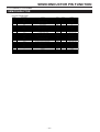
SEMICONDUCTOR PIN FUNCTION
S 1731 Indoor, S 1735 Indoor
SEMICONDUCTOR
IC1
Pin No.
1
2
3
4
5
6
7
8
9
10
11
12
13
14
15
16
17
18
19
20
21
22
23
24
25
26
27
28
29
30
31
32
33
34
35
36
37
38
39
40
41
42
43
44
45
46
47
48
49
50
51
52
53
54
55
56
57
58
59
60
61
62
63
64
Signal Name
Function
Sensor(Room Temp.)
Sensor(Heat Exchanger Temp.)
NC
A/D Input
A/D Input
NC
Munual Sw. Input
Motor(fan)
Buzzer
Pulse Input (Fan Motor Pulse)
NC
NC
NC
NC
NC
NC
NC
NC
MIN.Hz UP
Remote Controller Input
NC
Reset
NC
Zero Cross
Resonator In
Resonator Out
VSS
NC
NC
Ionizer Lamp
Power Lamp
Timer Mode Lamp
Operating Mode Lamp
NC
Power Relay
Motor(Louver D)
Motor(Louver C)
Motor(Louver B)
Motor(Louver A)
NC
NC
NC
NC
NC
NC
NC
Ionizer
A/D Inpuut
EXTERNAL CONTROL
AUTO RECOVERY OFF
NC
NC
EEPROM(SO)
Communication Output
Communication Input
NC
EEPROM(SI)
EEPROM(SK)
EEPROM(CS)
VCC
Vref
AVSS
NC
REMOTE CONTROLLER A/B
LOUVER CONTROL
NC
NC
Pulse= Communication Output
Communication Input
NC
EEPROM Serial Data Input
EEPROM Serial Data Clock
EEPROM Chip Select
5V POWER
A/D Reference Voltage
0V(GND)
NC
H= Btype L= Atype(Normal)
H= Off L= On(Normal)
NC
NC
Input
GND
Output
VCC
5V(or Pulse)= On¸0V= Off
0V(GND)
0V(or Pulse)= On¸12V= Off
12V
Munual Sw. Input
H= Motor(fan) On
4KHz Pulse= On
Pulse Input (Fan Motor Pulse)
NC
NC
NC
NC
NC
NC
NC
NC
H= MIN.Hz UP L= Normal
Remote Controller Signal
NC
L= Reset
NC
Zero Cross
Clock In
Clock Out
0V(GND)
NC
NC
L= Ionizer Lamp On
L= Power Lamp On
L= Timer Mode Lamp On
L= Operating Mode Lamp On
NC
L= Power Relay On
Pulse= On L= Off
Pulse= On L= Off
Pulse= On L= Off
Pulse= On L= Off
NC
NC
NC
NC
NC
NC
NC
H= Ionizer On
Change the Function
H= On L= Off(Normal)
H= Off L= On(Normal)
NC
NC
EEPROM Serial Data Output
In/Out
In
In
In
In
Out
Out
In
In
In
Out
In
In
In
In
In
In
In
In
In
In
In
In
Out
In
In
Out
Out
Out
Out
In
Out
Out
Out
Out
Out
Out
Out
Out
Out
Out
Out
Out
Out
In
In
In
In
In
Out
Out
In
In
In
Out
Out
In
Active
Voltage
L
H
H
H
H
L
L
L
L
L
H
H
H
H
H
H
H
H
-
See 53 Page
See 55 Page
0V
5Vor0V
See Fig 1
5V 4KHz Pulse(Duty50%)
See Fig 3
0V
0V
5V
0V
0V
5Vor0V
0V
5Vor0V
5V
See Fig. 2
10MHz
10MHz
0V
5V
5V
5Vor0V
5Vor0V
5Vor0V
5Vor0V
5V
5Vor0V
5Vor0V
5Vor0V
5Vor0V
5Vor0V
5Vor0V
3.4V
0.2V
0V
5V
0V
5Vor0V
5Vor0V
5Vor0V
5Vor0V
5Vor0V
5Vor0V
5V
5V
0V
0V
0.2V
In
-
-
0.2V
5V
5V
In
Out
-
L
H
-
5Vor0V
0V
12Vor0V
12V
IC3
1∼ 7
8
9∼ 15
16
– 45 –
SEMICONDUCTOR PIN FUNCTION
Fig.1
Fig.2
5V
5V
0V
0V
t= 10ms
t= 10ms
Fig.3
5V
0V
t=
20
s
R.P.M.(FAN MOTOR)
– 46 –
SEMICONDUCTOR PIN FUNCTION
S 1731 Outdoor, S 1735 Outdoor
SEMICONDUCTOR
IC2 PIN FUNCTION
Pin No.
1
2
3
4
5
6
7
8
9
10
11
12
13
14
15
16
17
18
19
20
21
22
23
24
25
26
27
Signal Name
VCCL
COML
INUL
INVL
INWL
VFO
CFOD
CSC
INUH
VCCUH
VBU
VSU
INVH
VCCVH
VBV
VSV
INWH
VCCWH
VBW
VSW
NU
NV
NW
U
V
W
P
Function
15V Power Supply
Common Supply GND
INVERTER U- Input
INVERTER V- Input
INVERTER W- Input
Alarm Output
Set Alarm Palse Width
DC Current Detection Input
INVERTER U+ Input
U+ IC Power Supply
U+ IGBT Driving Power Supply
U+ IGBT Driving GND
INVERTER V+ Input
V+ IC Power Supply
V+ IGBT Driving Power Supply
V+ IGBT Driving GND
INVERTER W+ Input
W+ IC Power Supply
W+ IGBT Driving Power Supply
W+ IGBT Driving GND
Nega. DC-Link U
Nega. DC-Link V
Nega. DC-Link W
Output U
Output V
Output W
Posi. DC-Link Input
– 47 –
In/Out
POWER
GND
In
In
In
Out
Out
In
In
POWER
POWER
GND
In
POWER
POWER
GND
In
POWER
POWER
GND
GND
GND
GND
Out
Out
Out
POWER
Active
H
H
H
L
H
H
-
Voltage
15V
0V
4Vor0V
4Vor0V
4Vor0V
5V
0V
0 - 0.5V
4Vor0V
15V
VBU-VSU= 15V
VBU-VSU= 15V
4Vor0V
15V
VBV-VSV= 15V
VBV-VSV= 15V
4Vor0V
15V
VBW-VSW= 15V
VBW-VSW= 15V
0V
0V
0V
0-360V
0-360V
0-360V
150-360V
SEMICONDUCTOR PIN FUNCTION
IC3 PIN FUNCTION
Pin No.
1
2
3
4N
5
6N
7N
Signal Name
VSS
Xin
Xout
C
VDD
C
C
8
RESET(IC4)
9N
10
11
12
13
14
15
16
17
18
19
20
21
22
23
24
25
26
27
28
29
30
31
32
33
34
35
36
37
38
39
40
41
42
43
44
45
46
47
48
49
50
51
52
53
54
55
56
57
58
59
60
61
62
63
64
65
66
67
68
69
70
71
72
73
74
75
76
77
78
79
80
C
IC9 14Pin
IC9 12Pin
IC9 10Pin
IC9 6Pin
IC9 4Pin
IC9 2Pin
DQ38
NC
IC11 14Pin
IC11 1Pin
IC11 13Pin
TEST CK
TEST SI
TEST SO
NC
IC10 5Pin
A/D Input
A/D Input
A/D Input
A/D Input
A/D Input
A/D Input
A/D Input
TEST Output
A/D Input
A/D Input
A/D Input
A/D Input
A/D Input
A/D Input
A/D Input
A/D Input
VAREF
AVDD
VASS
DQ34
NC
NC
IC6 7Pin
IC6 6Pin
IC6 5Pin
NC
NC
NC
NC
NC
NC
NC
NC
NC
NC
PC32
DQ33
NC
NC
NC
PC31
PC31
NC
DQ35
NC
NC
DQ36
NC
NC
NC
NC
IC5 1Pin
IC5 2Pin
IC5 3Pin
IC5 4Pin
Function
GND
Resonator In
Resonator Out
NC
IC3 Power Supply
NC
NC
IC3 RESET Input
Up to 4.2V= H
Less than 4.2V= L
NC
INVERTER¸-W¸Output
INVERTER¸-V¸Output
INVERTER¸-U¸Output
INVERTER¸+W¸Output
INVERTER¸+V¸Output
INVERTER¸+U¸Output
DC Over Current
NC
COMP. Position W
COMP. Position V
COMP. Position U
TEST CK
TEST SI
TEST SO
NC
DC Current Alarm Reset
DC Power Monitor
TEMP.,Module Sensor
NC
NC
NC
NC
TEMP.,Outdoor Sensor
TEST Output
TEMP.,Defrost Sensor
TEMP.,Discharge Sensor
NC
NC
NC
NC
NC
AC Current Sensor
A/D Refference Voltage
A/D Power Supply
A/D GND
Heater Output
NC
NC
4way Valve Output
Fan Motor Output
Power Relay Output
NC
NC
NC
NC
NC
NC
NC
NC
NC
NC
Communication Input
Communication Output
NC
NC
NC
Zero Cross
Zero Cross
NC
PFC IGBT Output
NC
NC
PFC On
NC
NC
NC
NC
EEPROM Chip Serect
EEPROM Clock
EEPROM Data Output
EEPROM Data Input
– 48 –
In/Out
GND
In
Out
In
POWER
In
In
In
In
Out
Out
Out
Out
Out
Out
In
In
In
In
In
Out
In
Out
In
Out
In
In
In
In
In
In
In
Out
In
In
In
In
In
In
In
In
POWER
POWER
GND
Out
Out
Out
Out
Out
Out
Out
Out
Out
Out
Out
Out
Out
Out
Out
Out
In
Out
Out
Out
Out
In
In
Out
Out
Out
Out
Out
Out
Out
Out
Out
Out
Out
Out
In
Active
-
Voltage
0V
14.7MHz
14.7MHz
0V
5V
0V
5V
L
H:5V
L:0V
H
H
H
H
H
H
L
L
L
L
H
H
H
L
H
H
H
H
H
H
L
L
H
L
H
-
5Vor0V
5Vor0V
5Vor0V
5Vor0V
5Vor0V
5Vor0V
5V
5V
5Vor0V
5Vor0V
5Vor0V
5Vor0V
5Vor0V
5Vor0V
5V
5Vor0V
0 - 5V
0 - 5V
0V
0V
0V
0V
0 - 5V
5Vor0V
0 - 5V
0 - 5V
0V
0V
0V
0V
2.5V
0 - 5V
5V
5V
0V
5Vor0V
5Vor0V
5Vor0V
5Vor0V
5Vor0V
5Vor0V
5Vor0V
5Vor0V
5Vor0V
5Vor0V
5Vor0V
-
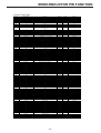
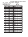
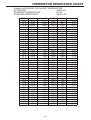
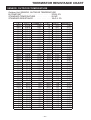
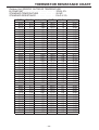
THERMISTOR RESISTANCE CHART
SENSOR, ROOM TEMPERATURE
Indoor Unit SENSOR, ROOM TEMPERATURE
B CONSTANT • • • • • • • • • • • • • • • • • • • • • • • • 4150±3%
STANDARD TEMPERATURE • • • • • • • • • • • • 25.0°C
STANDARD RESISTANCE • • • • • • • • • • • • • • 23kΩ±3%
T(°C)
-30.0
-29.5
-29.0
-28.5
-28.0
-27.5
-27.0
-26.5
-26.0
-25.5
-25.0
-24.5
-24.0
-23.5
-23.0
-22.5
-22.0
-21.5
-21.0
-20.5
-20.0
-19.5
-19.0
-18.5
-18.0
-17.5
-17.0
-16.5
-16.0
-15.5
-15.0
-14.5
-14.0
-13.5
-13.0
-12.5
-12.0
-11.5
-11.0
-10.5
-10.0
R(kΩ)
537.8
519.3
501.5
484.3
467.8
452.0
436.7
422.0
407.9
394.3
381.1
368.5
356.4
344.7
333.4
322.5
312.1
302.0
292.2
282.9
273.8
265.1
256.7
248.6
240.8
233.2
225.9
218.9
212.1
205.6
199.3
193.2
187.3
181.6
176.1
170.8
165.6
160.7
155.9
151.2
146.8
Voltage(V)
0.18
0.19
0.19
0.20
0.20
0.21
0.22
0.23
0.23
0.24
0.25
0.26
0.27
0.27
0.28
0.29
0.30
0.31
0.32
0.33
0.34
0.35
0.36
0.37
0.38
0.39
0.41
0.42
0.43
0.44
0.46
0.47
0.48
0.50
0.51
0.52
0.54
0.55
0.57
0.58
0.60
T(°C)
-10.0
-9.5
-9.0
-8.5
-8.0
-7.5
-7.0
-6.5
-6.0
-5.5
-5.0
-4.5
-4.0
-3.5
-3.0
-2.5
-2.0
-1.5
-1.0
-0.5
0.0
0.5
1.0
1.5
2.0
2.5
3.0
3.5
4.0
4.5
5.0
5.5
6.0
6.5
7.0
7.5
8.0
8.5
9.0
9.5
10.0
– 49 –
R(kΩ)
146.8
142.4
138.2
134.2
130.3
126.5
122.8
119.3
115.9
112.5
109.3
106.2
103.2
100.3
97.5
94.8
92.1
89.5
87.1
84.7
82.3
80.1
77.9
75.8
73.7
71.7
69.8
67.9
66.1
64.3
62.6
61.0
59.4
57.8
56.3
54.8
53.4
52.0
50.7
49.4
48.1
Voltage(V)
0.60
0.62
0.63
0.65
0.67
0.68
0.70
0.72
0.74
0.75
0.77
0.79
0.81
0.83
0.85
0.87
0.89
0.91
0.93
0.96
0.98
1.00
1.02
1.04
1.07
1.09
1.11
1.14
1.16
1.19
1.21
1.23
1.26
1.29
1.31
1.34
1.36
1.39
1.41
1.44
1.47
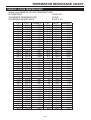
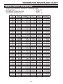
THERMISTOR RESISTANCE CHART
Indoor Unit SENSOR, ROOM TEMPERATURE
B CONSTANT • • • • • • • • • • • • • • • • • • • • • • • • 4150±3%
STANDARD TEMPERATURE • • • • • • • • • • • • • 25.0°C
STANDARD RESISTANCE • • • • • • • • • • • • • • • 23kΩ±3%
T(°C)
10.0
10.5
11.0
11.5
12.0
12.5
13.0
13.5
14.0
14.5
15.0
15.5
16.0
16.5
17.0
17.5
18.0
18.5
19.0
19.5
20.0
20.5
21.0
21.5
22.0
22.5
23.0
23.5
24.0
24.5
25.0
25.5
26.0
26.5
27.0
27.5
28.0
28.5
29.0
29.5
30.0
R(kΩ)
48.1
46.9
45.7
44.5
43.4
42.3
41.3
40.2
39.2
38.2
37.3
36.4
35.5
34.6
33.8
33.0
32.2
31.4
30.6
29.9
29.2
28.5
27.8
27.1
26.5
25.9
25.3
24.7
24.1
23.5
23.0
22.5
22.0
21.5
21.0
20.5
20.0
19.6
19.1
18.7
18.3
Voltage(V)
1.47
1.50
1.52
1.55
1.58
1.60
1.63
1.66
1.69
1.72
1.75
1.77
1.80
1.83
1.86
1.89
1.92
1.95
1.98
2.00
2.03
2.06
2.09
2.12
2.15
2.18
2.21
2.24
2.27
2.30
2.33
2.35
2.38
2.41
2.44
2.47
2.50
2.53
2.56
2.58
2.61
T(°C)
30.0
30.5
31.0
31.5
32.0
32.5
33.0
33.5
34.0
34.5
35.0
35.5
36.0
36.5
37.0
37.5
38.0
38.5
39.0
39.5
40.0
40.5
41.0
41.5
42.0
42.5
43.0
43.5
44.0
44.5
45.0
45.5
46.0
46.5
47.0
47.5
48.0
48.5
49.0
49.5
50.0
– 50 –
R(kΩ)
18.3
17.9
17.5
17.1
16.7
16.3
16.0
15.6
15.3
15.0
14.6
14.3
14.0
13.7
13.4
13.1
12.9
12.6
12.3
12.1
11.8
11.6
11.3
11.1
10.8
10.6
10.4
10.2
10.0
9.8
9.6
9.4
9.2
9.0
8.8
8.7
8.5
8.3
8.1
8.0
7.8
Voltage(V)
2.61
2.64
2.67
2.70
2.72
2.75
2.78
2.81
2.83
2.86
2.89
2.91
2.94
2.97
2.99
3.02
3.04
3.07
3.09
3.12
3.14
3.17
3.19
3.22
3.24
3.27
3.29
3.31
3.34
3.36
3.38
3.40
3.43
3.45
3.47
3.49
3.51
3.53
3.55
3.57
3.59
THERMISTOR RESISTANCE CHART
SENSOR, HEAT EXCHANGER TEMPERATURE
Indoor Unit SENSOR, HEAT EXCHANGER TEMPERATURE
B CONSTANT • • • • • • • • • • • • • • • • • • • • • • • • 3700±3%
STANDARD TEMPERATURE • • • • • • • • • • • • • 25.0°C
STANDARD RESISTANCE • • • • • • • • • • • • • • • 10kΩ±3%
T(°C)
-40.0
-39.0
-38.0
-37.0
-36.0
-35.0
-34.0
-33.0
-32.0
-31.0
-30.0
-29.0
-28.0
-27.0
-26.0
-25.0
-24.0
-23.0
-22.0
-21.0
-20.0
-19.0
-18.0
-17.0
-16.0
-15.0
-14.0
-13.0
-12.0
-11.0
-10.0
-9.0
-8.0
-7.0
-6.0
-5.0
-4.0
-3.0
-2.0
-1.0
0.0
R(kΩ)
319.4
298.4
279.0
261.0
244.3
228.8
214.4
201.0
188.5
176.9
166.1
156.1
146.7
138.0
129.8
122.2
115.1
108.5
102.3
96.4
91.0
85.9
81.1
76.7
72.5
68.5
64.9
61.4
58.1
55.1
52.2
49.5
46.9
44.5
42.3
40.1
38.1
36.2
34.5
32.8
31.2
Voltage(V)
0.05
0.05
0.06
0.06
0.07
0.07
0.08
0.08
0.09
0.09
0.10
0.10
0.11
0.12
0.12
0.13
0.14
0.15
0.16
0.17
0.17
0.18
0.20
0.21
0.22
0.23
0.24
0.26
0.27
0.28
0.30
0.31
0.33
0.34
0.36
0.38
0.40
0.42
0.44
0.46
0.48
T(°C)
0.0
1.0
2.0
3.0
4.0
5.0
6.0
7.0
8.0
9.0
10.0
11.0
12.0
13.0
14.0
15.0
16.0
17.0
18.0
19.0
20.0
21.0
22.0
23.0
24.0
25.0
26.0
27.0
28.0
29.0
30.0
31.0
32.0
33.0
34.0
35.0
36.0
37.0
38.0
39.0
40.0
– 51 –
R(kΩ)
31.2
29.7
28.2
26.9
25.6
24.4
23.3
22.2
21.2
20.2
19.3
18.4
17.6
16.8
16.1
15.4
14.7
14.1
13.5
12.9
12.4
11.8
11.3
10.9
10.4
10.0
9.6
9.2
8.8
8.5
8.1
7.8
7.5
7.2
6.9
6.7
6.4
6.2
6.0
5.7
5.5
Voltage(V)
0.48
0.50
0.52
0.55
0.57
0.60
0.62
0.65
0.67
0.70
0.73
0.76
0.79
0.82
0.85
0.88
0.92
0.95
0.98
1.02
1.05
1.09
1.13
1.16
1.20
1.24
1.28
1.32
1.36
1.40
1.44
1.48
1.52
1.57
1.61
1.65
1.70
1.74
1.78
1.83
1.87
THERMISTOR RESISTANCE CHART
Indoor Unit SENSOR, HEAT EXCHANGER TEMPERATURE
B CONSTANT • • • • • • • • • • • • • • • • • • • • • • • • 3700±3%
STANDARD TEMPERATURE • • • • • • • • • • • • • 25.0°C
STANDARD RESISTANCE • • • • • • • • • • • • • • • 10kΩ±3%
T(°C)
40.0
41.0
42.0
43.0
44.0
45.0
46.0
47.0
48.0
49.0
50.0
51.0
52.0
53.0
54.0
55.0
56.0
57.0
58.0
59.0
60.0
61.0
62.0
63.0
64.0
65.0
66.0
67.0
68.0
69.0
70.0
71.0
72.0
73.0
74.0
75.0
76.0
77.0
78.0
79.0
80.0
R(kΩ)
5.5
5.3
5.1
4.9
4.8
4.6
4.4
4.3
4.1
4.0
3.8
3.7
3.6
3.4
3.3
3.2
3.1
3.0
2.9
2.8
2.7
2.6
2.5
2.5
2.4
2.3
2.2
2.2
2.1
2.0
2.0
1.9
1.8
1.8
1.7
1.7
1.6
1.6
1.5
1.5
1.4
Voltage(V)
1.87
1.92
1.96
2.00
2.05
2.09
2.14
2.18
2.23
2.27
2.32
2.36
2.40
2.45
2.49
2.53
2.58
2.62
2.66
2.70
2.74
2.79
2.83
2.87
2.91
2.95
2.99
3.02
3.06
3.10
3.14
3.17
3.21
3.24
3.28
3.31
3.35
3.38
3.41
3.45
3.48
T(°C)
80.0
81.0
82.0
83.0
84.0
85.0
86.0
87.0
88.0
89.0
90.0
91.0
92.0
93.0
94.0
95.0
96.0
97.0
98.0
99.0
100.0
101.0
102.0
103.0
104.0
105.0
106.0
107.0
108.0
109.0
110.0
111.0
112.0
113.0
114.0
115.0
116.0
117.0
118.0
119.0
120.0
– 52 –
R(kΩ)
1.4
1.4
1.4
1.3
1.3
1.2
1.2
1.2
1.1
1.1
1.1
1.1
1.0
1.0
1.0
0.9
0.9
0.9
0.9
0.8
0.8
0.8
0.8
0.8
0.7
0.7
0.7
0.7
0.7
0.7
0.6
0.6
0.6
0.6
0.6
0.6
0.5
0.5
0.5
0.5
0.5
Voltage(V)
3.48
3.51
3.54
3.57
3.60
3.63
3.66
3.68
3.71
3.74
3.76
3.79
3.82
3.84
3.87
3.89
3.91
3.94
3.96
3.98
4.00
4.02
4.04
4.06
4.08
4.10
4.12
4.14
4.16
4.18
4.19
4.21
4.23
4.24
4.26
4.27
4.29
4.30
4.32
4.33
4.35
THERMISTOR RESISTANCE CHART
SENSOR, DEFROST TEMPERATURE
Outdoor Unit SENSOR, DEFROST TEMPERATURE
B CONSTANT • • • • • • • • • • • • • • • • • • • • • • • • 3700±3%
STANDARD TEMPERATURE • • • • • • • • • • • • • 25.0°C
STANDARD RESISTANCE • • • • • • • • • • • • • • • 10kΩ±3%
T(°C)
-40.0
-39.0
-38.0
-37.0
-36.0
-35.0
-34.0
-33.0
-32.0
-31.0
-30.0
-29.0
-28.0
-27.0
-26.0
-25.0
-24.0
-23.0
-22.0
-21.0
-20.0
-19.0
-18.0
-17.0
-16.0
-15.0
-14.0
-13.0
-12.0
-11.0
-10.0
-9.0
-8.0
-7.0
-6.0
-5.0
-4.0
-3.0
-2.0
-1.0
0.0
R(kΩ)
319.4
298.4
279.0
261.0
244.3
228.8
214.4
201.0
188.5
176.9
166.1
156.1
146.7
138.0
129.8
122.2
115.1
108.5
102.3
96.4
91.0
85.9
81.1
76.7
72.5
68.5
64.9
61.4
58.1
55.1
52.2
49.5
46.9
44.5
42.3
40.1
38.1
36.2
34.5
32.8
31.2
Voltage(V)
0.29
0.31
0.33
0.36
0.38
0.40
0.43
0.45
0.48
0.51
0.54
0.57
0.60
0.63
0.67
0.70
0.74
0.78
0.82
0.86
0.90
0.94
0.99
1.03
1.08
1.13
1.18
1.23
1.28
1.33
1.39
1.44
1.49
1.55
1.61
1.66
1.72
1.78
1.84
1.90
1.95
T(°C)
0.0
1.0
2.0
3.0
4.0
5.0
6.0
7.0
8.0
9.0
10.0
11.0
12.0
13.0
14.0
15.0
16.0
17.0
18.0
19.0
20.0
21.0
22.0
23.0
24.0
25.0
26.0
27.0
28.0
29.0
30.0
31.0
32.0
33.0
34.0
35.0
36.0
37.0
38.0
39.0
40.0
– 53 –
R(kΩ)
31.2
29.7
28.2
26.9
25.6
24.4
23.3
22.2
21.2
20.2
19.3
18.4
17.6
16.8
16.1
15.4
14.7
14.1
13.5
12.9
12.4
11.8
11.3
10.9
10.4
10.0
9.6
9.2
8.8
8.5
8.1
7.8
7.5
7.2
6.9
6.7
6.4
6.2
6.0
5.7
5.5
Voltage(V)
1.95
2.01
2.07
2.13
2.19
2.25
2.31
2.37
2.43
2.49
2.54
2.60
2.66
2.71
2.77
2.83
2.88
2.93
2.99
3.04
3.09
3.14
3.19
3.24
3.29
3.33
3.38
3.42
3.47
3.51
3.55
3.59
3.63
3.67
3.71
3.75
3.78
3.82
3.85
3.89
3.92
THERMISTOR RESISTANCE CHART
Outdoor Unit SENSOR, DEFROST TEMPERATURE
B CONSTANT • • • • • • • • • • • • • • • • • • • • • • • • 3700±3%
STANDARD TEMPERATURE • • • • • • • • • • • • • 25.0°C
STANDARD RESISTANCE • • • • • • • • • • • • • • • 10kΩ±3%
T(°C)
40.0
41.0
42.0
43.0
44.0
45.0
46.0
47.0
48.0
49.0
50.0
51.0
52.0
53.0
54.0
55.0
56.0
57.0
58.0
59.0
60.0
61.0
62.0
63.0
64.0
65.0
66.0
67.0
68.0
69.0
70.0
71.0
72.0
73.0
74.0
75.0
76.0
77.0
78.0
79.0
80.0
R(kΩ)
5.5
5.3
5.1
4.9
4.8
4.6
4.4
4.3
4.1
4.0
3.8
3.7
3.6
3.4
3.3
3.2
3.1
3.0
2.9
2.8
2.7
2.6
2.5
2.5
2.4
2.3
2.2
2.2
2.1
2.0
2.0
1.9
1.8
1.8
1.7
1.7
1.6
1.6
1.5
1.5
1.4
Voltage(V)
3.92
3.95
3.98
4.01
4.04
4.07
4.10
4.12
4.15
4.17
4.20
4.22
4.24
4.27
4.29
4.31
4.33
4.35
4.37
4.39
4.40
4.42
4.44
4.45
4.47
4.48
4.50
4.51
4.53
4.54
4.55
4.57
4.58
4.59
4.60
4.61
4.62
4.63
4.64
4.65
4.66
T(°C)
80.0
81.0
82.0
83.0
84.0
85.0
86.0
87.0
88.0
89.0
90.0
91.0
92.0
93.0
94.0
95.0
96.0
97.0
98.0
99.0
100.0
101.0
102.0
103.0
104.0
105.0
106.0
107.0
108.0
109.0
110.0
111.0
112.0
113.0
114.0
115.0
116.0
117.0
118.0
119.0
120.0
– 54 –
R(kΩ)
1.4
1.4
1.4
1.3
1.3
1.2
1.2
1.2
1.1
1.1
1.1
1.1
1.0
1.0
1.0
0.9
0.9
0.9
0.9
0.8
0.8
0.8
0.8
0.8
0.7
0.7
0.7
0.7
0.7
0.7
0.6
0.6
0.6
0.6
0.6
0.6
0.5
0.5
0.5
0.5
0.5
Voltage(V)
4.66
4.67
4.68
4.69
4.70
4.71
4.71
4.72
4.73
4.74
4.74
4.75
4.76
4.76
4.77
4.77
4.78
4.79
4.79
4.80
4.80
4.81
4.81
4.82
4.82
4.83
4.83
4.83
4.84
4.84
4.85
4.85
4.85
4.86
4.86
4.86
4.87
4.87
4.87
4.88
4.88
THERMISTOR RESISTANCE CHART
SENSOR, DISCHARGE TEMPERATURE
Outdoor Unit SENSOR, DISCHARGE TEMPERATURE
B CONSTANT • • • • • • • • • • • • • • • • • • • • • • • • 4250±3%
STANDARD TEMPERATURE • • • • • • • • • • • • • 80.0°C
STANDARD RESISTANCE • • • • • • • • • • • • • • • 50kΩ±3%
T(°C)
-40.0
-39.0
-38.0
-37.0
-36.0
-35.0
-34.0
-33.0
-32.0
-31.0
-30.0
-29.0
-28.0
-27.0
-26.0
-25.0
-24.0
-23.0
-22.0
-21.0
-20.0
-19.0
-18.0
-17.0
-16.0
-15.0
-14.0
-13.0
-12.0
-11.0
-10.0
-9.0
-8.0
-7.0
-6.0
-5.0
-4.0
-3.0
-2.0
-1.0
0.0
R(kΩ) Voltage(V)
33007.9
0.01
30420.9
0.01
28056.1
0.01
25892.9
0.01
23912.6
0.01
22098.6
0.01
20435.7
0.01
18910.2
0.01
17509.9
0.01
16223.6
0.01
15041.2
0.02
13953.6
0.02
12952.7
0.02
12030.8
0.02
11181.2
0.02
10397.7
0.02
9674.8
0.02
9007.3
0.03
8390.7
0.03
7820.6
0.03
7293.4
0.03
6805.4
0.03
6353.6
0.04
5934.9
0.04
5546.7
0.04
5186.7
0.04
4852.5
0.05
4542.2
0.05
4253.9
0.05
3985.9
0.06
3736.6
0.06
3504.7
0.07
3288.7
0.07
3087.5
0.07
2900.0
0.08
2725.1
0.08
2562.0
0.09
2409.7
0.10
2267.5
0.10
2134.7
0.11
2010.5
0.11
T(°C)
0.0
1.0
2.0
3.0
4.0
5.0
6.0
7.0
8.0
9.0
10.0
11.0
12.0
13.0
14.0
15.0
16.0
17.0
18.0
19.0
20.0
21.0
22.0
23.0
24.0
25.0
26.0
27.0
28.0
29.0
30.0
31.0
32.0
33.0
34.0
35.0
36.0
37.0
38.0
39.0
40.0
– 55 –
R(kΩ)
2010.5
1894.4
1785.8
1684.1
1588.9
1499.6
1416.0
1337.6
1264.1
1195.0
1130.2
1069.3
1012.1
958.4
907.8
860.2
815.4
773.3
733.5
696.1
660.8
627.6
596.2
566.6
538.6
512.2
487.2
463.6
441.4
420.3
400.3
381.4
363.6
346.6
330.6
315.4
301.0
287.3
274.4
262.1
250.4
Voltage(V)
0.11
0.12
0.13
0.14
0.14
0.15
0.16
0.17
0.18
0.19
0.20
0.21
0.22
0.23
0.25
0.26
0.27
0.29
0.30
0.32
0.33
0.35
0.37
0.38
0.40
0.42
0.44
0.46
0.48
0.50
0.53
0.55
0.57
0.60
0.62
0.65
0.68
0.70
0.73
0.76
0.79
THERMISTOR RESISTANCE CHART
Outdoor Unit SENSOR, DISCHARGE TEMPERATURE
B CONSTANT • • • • • • • • • • • • • • • • • • • • • • • • 4250±3%
STANDARD TEMPERATURE • • • • • • • • • • • • • 80.0°C
STANDARD RESISTANCE • • • • • • • • • • • • • • • 50kΩ±3%
T(°C)
40.0
41.0
42.0
43.0
44.0
45.0
46.0
47.0
48.0
49.0
50.0
51.0
52.0
53.0
54.0
55.0
56.0
57.0
58.0
59.0
60.0
61.0
62.0
63.0
64.0
65.0
66.0
67.0
68.0
69.0
70.0
71.0
72.0
73.0
74.0
75.0
76.0
77.0
78.0
79.0
80.0
R(kΩ)
250.4
239.3
228.8
218.8
209.3
200.2
191.6
183.5
175.7
168.3
161.2
154.5
148.1
142.0
136.2
130.7
125.4
120.4
115.6
111.0
106.6
102.4
98.4
94.6
91.0
87.5
84.2
81.0
77.9
75.0
72.2
69.5
67.0
64.5
62.2
59.9
57.8
55.7
53.7
51.8
50.0
Voltage(V)
0.79
0.82
0.85
0.88
0.92
0.95
0.98
1.02
1.06
1.09
1.13
1.17
1.20
1.24
1.28
1.32
1.36
1.40
1.45
1.49
1.53
1.57
1.62
1.66
1.70
1.75
1.79
1.84
1.88
1.93
1.97
2.02
2.06
2.11
2.15
2.20
2.24
2.29
2.33
2.38
2.42
– 56 –
T(°C)
80.0
81.0
82.0
83.0
84.0
85.0
86.0
87.0
88.0
89.0
90.0
91.0
92.0
93.0
94.0
95.0
96.0
97.0
98.0
99.0
100.0
101.0
102.0
103.0
104.0
105.0
106.0
107.0
108.0
109.0
110.0
111.0
112.0
113.0
114.0
115.0
116.0
117.0
118.0
119.0
120.0
R(kΩ)
50.0
48.3
46.6
45.0
43.4
41.9
40.5
39.1
37.8
36.5
35.3
34.2
33.0
32.0
30.9
29.9
28.9
28.0
27.1
26.3
25.4
24.6
23.9
23.1
22.4
21.7
21.1
20.4
19.8
19.2
18.6
18.1
17.5
17.0
16.5
16.0
15.6
15.1
14.7
14.3
13.9
Voltage(V)
2.42
2.47
2.51
2.56
2.60
2.64
2.69
2.73
2.77
2.81
2.85
2.90
2.94
2.98
3.02
3.06
3.09
3.13
3.17
3.21
3.24
3.28
3.32
3.35
3.39
3.42
3.45
3.49
3.52
3.55
3.58
3.61
3.64
3.67
3.70
3.73
3.76
3.78
3.81
3.84
3.86
THERMISTOR RESISTANCE CHART
SENSOR, OUTDOOR TEMPERATURE
Outdoor Unit SENSOR, OUTDOOR TEMPERATURE
B CONSTANT • • • • • • • • • • • • • • • • • • • • • • • • 3700±3%
STANDARD TEMPERATURE • • • • • • • • • • • • • 25.0°C
STANDARD RESISTANCE • • • • • • • • • • • • • • • 10kΩ±3%
T(°C)
-40.0
-39.0
-38.0
-37.0
-36.0
-35.0
-34.0
-33.0
-32.0
-31.0
-30.0
-29.0
-28.0
-27.0
-26.0
-25.0
-24.0
-23.0
-22.0
-21.0
-20.0
-19.0
-18.0
-17.0
-16.0
-15.0
-14.0
-13.0
-12.0
-11.0
-10.0
-9.0
-8.0
-7.0
-6.0
-5.0
-4.0
-3.0
-2.0
-1.0
0.0
R(kΩ)
319.4
298.4
279.0
261.0
244.3
228.8
214.4
201.0
188.5
176.9
166.1
156.1
146.7
138.0
129.8
122.2
115.1
108.5
102.3
96.4
91.0
85.9
81.1
76.7
72.5
68.5
64.9
61.4
58.1
55.1
52.2
49.5
46.9
44.5
42.3
40.1
38.1
36.2
34.5
32.8
31.2
Voltage(V)
0.29
0.31
0.33
0.36
0.38
0.40
0.43
0.45
0.48
0.51
0.54
0.57
0.60
0.63
0.67
0.70
0.74
0.78
0.82
0.86
0.90
0.94
0.99
1.03
1.08
1.13
1.18
1.23
1.28
1.33
1.39
1.44
1.49
1.55
1.61
1.66
1.72
1.78
1.84
1.90
1.95
T(°C)
0.0
1.0
2.0
3.0
4.0
5.0
6.0
7.0
8.0
9.0
10.0
11.0
12.0
13.0
14.0
15.0
16.0
17.0
18.0
19.0
20.0
21.0
22.0
23.0
24.0
25.0
26.0
27.0
28.0
29.0
30.0
31.0
32.0
33.0
34.0
35.0
36.0
37.0
38.0
39.0
40.0
– 57 –
R(kΩ)
31.2
29.7
28.2
26.9
25.6
24.4
23.3
22.2
21.2
20.2
19.3
18.4
17.6
16.8
16.1
15.4
14.7
14.1
13.5
12.9
12.4
11.8
11.3
10.9
10.4
10.0
9.6
9.2
8.8
8.5
8.1
7.8
7.5
7.2
6.9
6.7
6.4
6.2
6.0
5.7
5.5
Voltage(V)
1.95
2.01
2.07
2.13
2.19
2.25
2.31
2.37
2.43
2.49
2.54
2.60
2.66
2.71
2.77
2.83
2.88
2.93
2.99
3.04
3.09
3.14
3.19
3.24
3.29
3.33
3.38
3.42
3.47
3.51
3.55
3.59
3.63
3.67
3.71
3.75
3.78
3.82
3.85
3.89
3.92
THERMISTOR RESISTANCE CHART
Outdoor Unit SENSOR, OUTDOOR TEMPERATURE
B CONSTANT • • • • • • • • • • • • • • • • • • • • • • • • 3700±3%
STANDARD TEMPERATURE • • • • • • • • • • • • • 25.0°C
STANDARD RESISTANCE • • • • • • • • • • • • • • • 10kΩ±3%
T(°C)
40.0
41.0
42.0
43.0
44.0
45.0
46.0
47.0
48.0
49.0
50.0
51.0
52.0
53.0
54.0
55.0
56.0
57.0
58.0
59.0
60.0
61.0
62.0
63.0
64.0
65.0
66.0
67.0
68.0
69.0
70.0
71.0
72.0
73.0
74.0
75.0
76.0
77.0
78.0
79.0
80.0
R(kΩ)
5.5
5.3
5.1
4.9
4.8
4.6
4.4
4.3
4.1
4.0
3.8
3.7
3.6
3.4
3.3
3.2
3.1
3.0
2.9
2.8
2.7
2.6
2.5
2.5
2.4
2.3
2.2
2.2
2.1
2.0
2.0
1.9
1.8
1.8
1.7
1.7
1.6
1.6
1.5
1.5
1.4
Voltage(V)
3.92
3.95
3.98
4.01
4.04
4.07
4.10
4.12
4.15
4.17
4.20
4.22
4.24
4.27
4.29
4.31
4.33
4.35
4.37
4.39
4.40
4.42
4.44
4.45
4.47
4.48
4.50
4.51
4.53
4.54
4.55
4.57
4.58
4.59
4.60
4.61
4.62
4.63
4.64
4.65
4.66
T(°C)
80.0
81.0
82.0
83.0
84.0
85.0
86.0
87.0
88.0
89.0
90.0
91.0
92.0
93.0
94.0
95.0
96.0
97.0
98.0
99.0
100.0
101.0
102.0
103.0
104.0
105.0
106.0
107.0
108.0
109.0
110.0
111.0
112.0
113.0
114.0
115.0
116.0
117.0
118.0
119.0
120.0
– 58 –
R(kΩ)
1.4
1.4
1.4
1.3
1.3
1.2
1.2
1.2
1.1
1.1
1.1
1.1
1.0
1.0
1.0
0.9
0.9
0.9
0.9
0.8
0.8
0.8
0.8
0.8
0.7
0.7
0.7
0.7
0.7
0.7
0.6
0.6
0.6
0.6
0.6
0.6
0.5
0.5
0.5
0.5
0.5
Voltage(V)
4.66
4.67
4.68
4.69
4.70
4.71
4.71
4.72
4.73
4.74
4.74
4.75
4.76
4.76
4.77
4.77
4.78
4.79
4.79
4.80
4.80
4.81
4.81
4.82
4.82
4.83
4.83
4.83
4.84
4.84
4.85
4.85
4.85
4.86
4.86
4.86
4.87
4.87
4.87
4.88
4.88
EXPLODED VIEW (INDOOR UNIT)
S 1731 Indoor
accessories
26
25
11
27
22
30
28
15
29
20
23
14
30
24
9
13
1
4
6
5
21
2
12
3
10
7
8
19
16
31
18
17
– 59 –
EXPLODED VIEW (INDOOR UNIT)
S 1735 Indoor
21
25
24
26
30
28
27
22
14
13
10
23
8
12
19
6
4
5
1
2
3
11
26
7
20
18
15
20
29
17
9
– 60 –
16
EXPLODED VIEW (OUTDOOR UNIT)
S 1731 Outdoor
S 1735 Outdoor
11
6
1
9
14
22
10
13
18
23
25
29
5
19
12
3
15
28
2
26
8
20
21
24
30
7
4
17
accessories
16
27
– 61 –
31
PARTS LIST (INDOOR UNIT)
NO.
S 1731 Indoor
1
CONTROLLER ASSY.
20446670
2
PCB (MAIN)
30066610
3
PCB (RECEIVER & DISPLAY)
30055510
30013610
4
SENSOR
(TEMP,ROOM & HEAT EXCHAGER)
5
30055070
30054290
30021680
6
TRANSFORMER
51955370
30055520
7
TERMINAL BLOCK
51620840
8
CORD,POWER SUPPLY
30021550
9
FRONT PANEL
20088190
10
INLET GRILLE
20431521
11
REAR CASE ASSY.
20050160
12
WIRING LID
20044490
53501600
13
MOTOR,FAN
30063700
53501710
50810080
14
TANGENTIAL FAN
50810090
15
BEARING ASSY.
20048330
16
DRAIN PAN ASSY.
20412632
30061390
51621030
17
MOTOR,LOUVER
51621010
30027370
51621040
18
LOUVER (UP-DOWN)
20044430
19
DRAIN HOSE
51620000
20
EVAPORATOR ASSY.
20435501
21
AIR FILTER
20096300
22
MOUNTING PLATE ASSY.
20173950
23
PIPING SUPPORT
20044410
24
MOTOR SUPPORT
20044420
25
REMOTE CONTROLLER
20431870
26
REMOTE CONTROLLER HOLDER
20139550
27
SCREW CAP
20048420
28
BATTERY
30057750
29
DRAIN ELBOW
20148080
30
AIR CLEAN FILTER
30063040
31
IONIZER
30055490
– 62 –
PARTS LIST (INDOOR UNIT)
NO.
PARTS NAME
S 1735 Indoor
1
CONTROLLER ASSY.
20446680
2
PCB (MAIN)
30066620
3
PCB (RECEIVER & DISPLAY)
30055510
30013610
4
SENSOR
(TEMP,ROOM & HEAT EXCHAGER)
5
30055070
30054290
6
TERMINAL BLOCK
51620840
7
CORD,POWER SUPPLY
30021550
8
FRONT PANEL ASSY.
20088200
9
INLET GRILLE
20431521
10
REAR CASE ASSY.
20048710
11
WIRING LID
20044490
12
MOTOR,FAN
53501610
30063710
50810090
13
TANGENTIAL FAN
50810060
50810080
14
BEARING ASSY.
20048330
15
DRAIN PAN ASSY.
20412632
30061390
51621030
16
MOTOR,LOUVER
51621010
30027370
51621040
17
LOUVER (UP-DOWN)
20044450
18
DRAIN HOSE
51620000
19
EVAPORATOR ASSY.
20422600
20
AIR FILTER
20205120
21
MOUNTING PLATE ASSY.
20173950
22
PIPING SUPPORT
20044410
23
MOTOR SUPPORT
20045050
24
REMOTE CONTROLLER ASSY.
20431870
25
REMOTE CONTROLLER HOLDER
20139550
26
SCREW CAP
20048420
27
BATTERY
30057750
28
DRAIN ELBOW
20148080
29
IONIZER
30055490
30
AIR CLEAN FILTER
30063040
– 63 –
PARTS LIST (OUTDOOR UNIT)
NO.
PARTS NAME
S 1731 Outdoor
S 1735 Outdoor
1
TOP PANEL ASSY.
20444970
←
2
FRONT PANEL
20413612
←
3
COMPRESSOR
30061680
←
4
BOTTOM PANEL ASSY.
20445011
←
5
RIGHT SIDE PANEL ASSY.
20415191
←
6
LEFT SIDE PANEL ASSY.
20415201
←
7
VIBRATION PROOF RUBBER (comp.)
30061700
←
8
VALVE COVER
20130230
←
9
BAFFLE PANEL ASSY.
20447540
←
←
10
REACTOR
30055560
11
CONDENSER ASSY.
20415340
←
12
PROPELLER FAN
30056370
←
13
MOTOR
30066600
←
14
BRACKET, MOTOR
20415272
←
15
OUTLET GRILLE
20414980
←
16
CONTROLLER ASSY.
20446490
20446500
17
TERMINAL BLOCK
51620820
←
18
COIL,4-WAY VALVE
51202320
←
19
4-WAY VALVE ASSY.
20437580
←
20
VALVE,SERVICE (1/4)
51535620
←
21
VALVE,SERVICE (3/8)
30056350
←
51100960
22
SENSOR (TEMP.DEFROST)
←
23
30054280
←
51100870
←
30054310
←
SENSOR (TEMP.DISCHARGE)
24
SOUND PROOF MATERIAL1
20437720
←
25
SOUND PROOF MATERIAL2
20437730
←
26
SOUND PROOF MATERIAL3
20439090
←
27
VIBRATION PROOF RUBBER (UNIT)
20046680
←
28
FIXTURE,CORD
20038190
←
29
SENSOR (TEMP.OUTDOOR)
30067680
←
30
DEFROST HEATER
30066390
←
31
GUM BUSHING
20148090
←
– 64 –
RA-42-[1]
ISSUED
DEC.2005
Printed in Japan