1
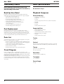
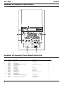
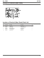
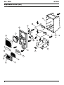
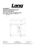
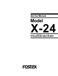
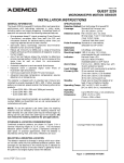
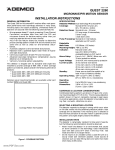
Mar. 2008
MT-90U
SERVICE NOTES
Issued by RJA
Table of Contents
Cautionary Notes ..............................................................2
Main Specifications ...........................................................2
Location of Controls (Front Panel) .................................4
Location of Controls (Front Panel) Parts List................4
Location of Controls (Rear Panel)...................................5
Location of Controls (Rear Panel) Parts List .................5
Exploded View (All) .........................................................6
Exploded View (All) Parts List........................................7
Exploded View (1).............................................................8
Exploded View (1) Parts List ...........................................9
Exploded View (2)...........................................................10
Exploded View (2) Parts List .........................................10
Important Notes on Assembly ......................................11
Block Diagram/Wiring Diagram..................................14
Parts List ...........................................................................16
Verifying the Version Number......................................18
Performing a Factory Reset............................................18
Updating the System ......................................................18
Test Mode .........................................................................18
Circuit Board (Main Board) ...........................................22
Circuit Diagram (Main Board: 1/4) ..............................24
Circuit Diagram (Main Board: 2/4) ..............................26
Circuit Diagram (Main Board: 3/4) ..............................27
Circuit Diagram (Main Board: 4/4) ..............................28
Circuit Board (Panel Board)...........................................30
Circuit Diagram (Panel Board)......................................32
Circuit Board (Jack, Volume, IR, USB, Power SW
Board)................................................................................34
Circuit Diagram (Jack Board: 1/3)................................36
Circuit Diagram (Jack Board: 2/3)................................38
Circuit Diagram (Jack Board: 3/3)................................40
Circuit Diagram (Volume Board)..................................42
Circuit Diagram (IR Board)............................................44
Circuit Diagram (USB Board) ........................................44
Circuit Diagram (Power SW Board) .............................45
Copyright © 2008 Roland Corporation
All rights reserved. No part of this publication may be reproduced in any form without the written permission
of Roland Cororation.
17058572E0
Printed in Japan (0285) (CC-KWS)
Mar. 2008
MT-90U
Cautionary Notes
Main Specifications
Before beginning the procedure, please read
through this document. The matters described may
differ according to the model.
MT-90U: Music Player
Back Up User Data!
Playback Composer
Executing a Factory Reset returns the following settings to their factory
defaults. These cannot be backed up. Note them down on paper as required.
External Memory
•
Tuning settings (Owner’s Manual p. 17)
•
USB Memory (sold separately)
•
Metronome tone (Owner’s Manual p. 47)
•
Floppy Disk
•
Count sound settings (Owner’s Manual p. 48)
•
Lyrics-display language setting (Owner’s Manual p. 49)
•
Track Assign settings (Owner’s Manual p. 50)
•
Setting the Type and Timing of CD to be Played Back
(Owner’s Manual p.51)
•
USB memory settings (Owner’s Manual p. 52)
* Read only
•
USB driver settings (Owner’s Manual p. 52)
* Commercial USB CD drive required
Part Replacement
When replacing components near the power-supply circuit or a heatgenerating circuit (such as a circuit provided with a heat sink or including a
cement resistor), carry out the procedure according to the instructions with
respect to the part number, direction, and attachment position (mounting so as
to leave an air gap between the component and the circuit board, etc.).
* Read only
* USB 3.5 in. floppy disk drive (FD-01 series) required (sold separately)
•
CD-ROM
•
Audio CD
Supported Data
•
Standard MIDI Files (format 0/1)
•
Roland Original Format
•
Audio files (WAV; 44.1 kHz, 16 bit linear format)
•
MP3 files (44.1 kHz, 32 to 320 kbps)
•
Audio CD
* Commercial USB CD drive required
Parts List
A component whose part code is ******** cannot be supplied as a service part
because one of the following reasons applies.
•
Because it is supplied as an assembled part (under a different part code).
•
Because a number of circuit boards are grouped together and supplied as
a single circuit board (under a different part code).
•
Because supply is prohibited due to copyright restrictions.
•
Because reissuance is restricted.
•
Because the part is made to order (at current market price).
Circuit Diagram
In the circuit diagram, “NIU” is an abbreviation for “Not in Use,” and
“UnPop” is an abbreviation for “Unpopulated.” They both mean non-mounted
components. The circuit board and circuit board diagram show silk-screened
indications, but no components are mounted.
In the Main Board Circuit Diagram (p. 24), red parts on the PDF and gray parts
on paper media service notes mean non-mounted components. The circuit
board and circuit diagram show silk-screened indications, but no components
are mounted.
Tracks
16 tracks
Control
Reset, Stop, Play, Bwd, Fwd, Repeat, Marker, Song, Tempo, [+], [-], Track
Selection, Count In, Metronome (MIDI only), Center Cancel (audio only)
Tempo
Quarter note = 10 to 500 (MIDI only)
75 to 125% (audio only)
Resolution
120 ticks per quarter note (MIDI only)
Transpose
-6 to +5 (semitones)
Demo Songs
14 songs
2
Mar. 2008
Sound Generator
MT-90U
Rated Power Output
5W
Max. Polyphony
128 voices (MIDI only)
Speakers
10 cm x 1
Tones
348 tones (including 8 drum sets, 1 effects set)
Internal Sounds
Conforms to GM2 system/GS format/XGlite supported
Master Tuning
415.3 Hz to 466.2 Hz (0.1 Hz units)
Connectors
External memory connector:
USB type A
USB connector:
USB type B
Output jack (R/L):
RCA pin type
Microphone jack (Mono):
Standard type
Headphones jack:
Stereo, mini type
MIDI In connector
Start/Stop jack
Power Supply
Effects
Reverb (MIDI only)
Chorus (MIDI only)
Sound Control: Sharp, Clear, Power
DC9V
Current Draw
2000 mA
Sequencer
Metronome
Time Signatures:
2/2, 0/4, 2/4, 3/4, 4/4, 5/4, 6/4, 7/4, 3/8, 6/8, 9/8, 12/8
Volume:
11 levels
Pattern:
11 patterns
Other Functions
Dimensions
165 (W) x 186 (D) x 270 (H) mm
6-1/2 (W) x 7-3/8 (D) x 10-11/16 (H) inches
Weight
2.5 Kg / 5 lbs 9 oz
Accessories
AC Adaptor (#04236101)
•
Infrared Transmission
•
Mic Echo
for 220 V CN (#5100000564)
•
Song List
for 230 V E (#5100000115)
•
Floppy Disk Backup
for 230 V EU (#01903356)
Power Code
for 120 V (#02562456)
for 240 V A (#03785590)
Remote Control (#04898434)
Others
Display
Beat Indicator
122 x 32 dot, Graphic LCD (with backlight)
Lithium Battery (CR2025) (#********)
Owner’s Manual English (#04787745)
Options
USB Memory (M-UF1GB)
Floppy Disk Drive (FD-01 series)
Roland Microphone (DR-10/20)
Language
Pedal Switch (DP-2)
Japanese (song title, lyrics), English
Lyric Display
Yes (LCD display)
* In the interest of product improvement, the specifications and/or appearance of
this unit are subject to change without prior notice.
Controls
•
Volume
•
Mic volume
•
Mic echo
•
Speaker switch
3
Mar. 2008
MT-90U
Location of Controls (Front Panel)
fig.FrontPanel.eps
1
2
3
9
5
6
7
8
10
4
11
12
Location of Controls (Front Panel) Parts List
No.
1
2
3
4
5
6
7
8
9
10
11
12
4
Part Code
04787512
04780545
04892901
04787623
05017756
04787612
04787567
04787590
04780456
04787589
02015623
02341689
04787490
05017823
04787645
04787556
04673667
03342178
04560101
Part Name
DISPLAY COVER
LCD
RADIAL LED (2COLOR RED/GREEN)
R-KNOB MF
14MM ROTARY VOLUME (STEREO)
RUBBER SWITCH
LED LENS 4P
LED LENS 5P
LED (RED)
LED LENS 1P
LED (GREEN)
3.5MM JACK
BUTTON
POWER SWITCH
FRONT PANEL
IRDA COVER
INFRARED TRANSCEIVER MODULE
IC
USB CONNECTOR A TYPE FEMALE
Description
221-3065-0784
L-3749ESGC
F14KH-1 B10K L15 FCX7
L-314ED
SLR-342MG3F
HTJ-035-28
PWL-2P1TL-6SASTC-001
TFDU4101-TT3
GP1UM261RK0F
UAR27-4K5J00
Q’ty
1
1
1
1
1
1
1
1
4
1
6
1
1
1
1
1
1
1
1
Mar. 2008
MT-90U
Location of Controls (Rear Panel)
fig.RearPanel.eps
1
6
10
2
3
4
5
7
8
9
Location of Controls (Rear Panel) Parts List
No.
1
2, 8
3, 4
5
6
7
9
10
Part Code
02341634
00569278
04890223
04890689
05014890
03909767
01459945
40454856
Part Name
DC JACK HTJ-020-05A
6.5MM JACK
9MM VOLUME
SLIDE SWITCH
PIN JACK 2L2P WR NI
DIN CONNECTOR
USB CONNECTOR
SCREW M4X10
Description
(610-00100-04-00)
LGR4609-7100F
VX09211NPP20U1B20K
SKA-22D01N-G6-NA
HSP-242V1P-01
HDC-052A-11
YKF45-0002
BINDING NI
Q’ty
1
2
2
1
1
1
1
1
5
Mar. 2008
MT-90U
Exploded View (All)
fig.bunkaizu-all.eps
w1
Vie
View3
1
16
8
2
View4
w6
Vie
3
w2
Vie
w7
Vie
View5
7
6
9
w8
Vie
13
w9
Vie
19
12
17
11
18
6
20
15
5
10
4
14
Mar. 2008
MT-90U
Exploded View (All) Parts List
No.
1
2
3
4
5
6
7
8
9
10
11
12
13
14
15
16
17
18
19
20
Part Code
04787601
04787534
02342712
04780545
04787634
04787556
04898312
04898334
04898367
05122112
04787612
04898378
04787501
04898301
04785823
04898290
04787623
04787490
04787512
01235378
Part Name
REAR CASE
FRONT CASE
SPEAKER FULL-RANGE
LCD
SP GRILLE + NET
IRDA COVER
IR BOARD ASSY
VOLUME BOARD ASSY
SW BOARD ASSY
FRONT PANEL WITH LED LENS
RUBBER SWITCH
PANEL BOARD ASSY
CHASSIS
USB BOARD ASSY
MAIN BOARD ASSY
JACK BOARD ASSY
R-KNOB MF
BUTTON
DISPLAY COVER
FOOT
Description
221-3065-0784
Q’ty
1
1
1
1
1
1
1
1
1
1
1
1
1
1
1
1
1
1
1
4
7
Mar. 2008
MT-90U
Exploded View (1)
fig.bunkaizu-1.eps
View1
View2
b
f
e
c
View3
a
View4
f
View5
f
View6
f
a
8
Mar. 2008
MT-90U
Exploded View (1) Parts List
View 1, 2
No.
a
b
c
e
f
Part Code
40011312
40012490
40011334
40454856
03904456
Part Name
SCREW 3X8
SCREW 4X10
SCREW 3X12
SCREW M4X10
SCREW 3X6
Description
BINDING TAPTITE P BZC
BINDING TAPTITE P BZC
BINDING TAPTITE-P FE BZC
BINDING NI
B-TITE BIND BZC
Q’ty
5
4
1
1
4
Part Name
SCREW 3X6
Description
B-TITE BIND BZC
Q’ty
8
Part Name
SCREW 3X8
SCREW 3X6
Description
BINDING TAPTITE P BZC
B-TITE BIND BZC
Q’ty
6
2
View 3, 4
No.
f
Part Code
03904456
View 5, 6
No.
a
f
Part Code
40011312
03904456
9
Mar. 2008
MT-90U
Exploded View (2)
fig.bunkaizu-2.eps
View7
View8
b
a
a
d
a
View9
a
Exploded View (2) Parts List
View 7, 8, 9
No.
a
b
d
10
Part Code
40011312
40012490
40012867
Part Name
SCREW 3X8
SCREW 4X10
SCREW M3X8
Description
BINDING TAPTITE P BZC
BINDING TAPTITE P BZC
PAN MACHINE W/SW+PW ZC
Q’ty
19
4
2
Mar. 2008
MT-90U
Important Notes on Assembly
To prevent damage to the wiring, cover edges using acetate tape.
fig.kumitate-1.eps
To prevent screeching (unpleasant noise caused by vibration), apply acetate
tape having a width of 10 mm to the front case.
fig.kumitate-3-e.eps
10mm
Apply 1 strip.
10mm
10mm
Apply 2 overlapping strips.
Apply 2 overlapping strips.
fig.kumitate-2.eps
10mm
10mm
10mm
Apply 1 strip.
25mm
25mm
fig.kumitate-4-e.eps
Acetate tape
OK
Not OK
Front case
11
Mar. 2008
MT-90U
To prevent dust entry, apply cushion tape to the LCD unit. Do not peel off the
backing paper.
Secure the LCD wiring in place on the back of the front case using acetate tape.
fig.kumitate-8.eps
fig.kumitate-5-e.eps
Do not peel off
the backing paper.
fig.kumitate-9-e.eps
To prevent light leakage by the LCD backlight from the speaker grille, apply
acetate tape having a width of 12 mm.
fig.kumitate-6.eps
Not OK
Secure the IrDA cover in place using double-sided adhesive tape having a
width of 5 mm.
fig.kumitate-10.eps
fig.kumitate-7-e.eps
fig.kumitate-11.eps
Not OK
12
Mar. 2008
MT-90U
As a measure to prevent electromagnetic interference (EMI), attach Wiring J-2
to the Volume Board. Be careful to attach at the correct angle.
Twist the 9-pin wiring connecting the Jack Board and Volume Board 3 turns.
fig.kumitate-15-e.eps
fig.kumitate-12.eps
Twist 3 turns.
Also secure the 9-pin wiring and 3-pin wiring using a sub-tie.
fig.kumitate-16.eps
fig.kumitate-13-e.eps
Attachment angle
not OK
3-pin
9-pin
Apply cushion tape for protecting the wiring to the Jack Board. Take care not
to cover the screw hole.
fig.kumitate-14.eps
To keep the volume control from coming loose, apply double-sided adhesive
tape having a width of 5 mm to the volume shaft.
fig.kumitate-17.eps
20mm
fig.kumitate-18-e.eps
Double-sided
adhesive tape
Volume control
13
Mar. 2008
MT-90U
Block Diagram/Wiring Diagram
fig.block.eps@L
W1
W2
W3
W4
14
Mar. 2008
MT-90U
fig.block.eps@R
W5
W6
W7
W8
W9
W10
W11
No.
W1
W2
W3
W4
W5
W6
W7
W8
W9
W10
W11
Part Code
04894167
05012456
04894145
05012067
04894156
04894134
04894201
05011167
04894178
04894189
04894190
Part Name
WIRING
WIRING J-2
WIRING
WIRING J-1
WIRING USB
WIRING
WIRING FFC
WIRING SHIELD
WIRING SP
WIRING FFC
WIRING FFC
Description
SW 2P L=120 UL1061 AWG22 VHR
3P L=50 UL1061 AWG26 PHR-PHR
5P L=130 UL20276 PHR-PHR
6P L=90 UL1061 AWG26 PHR-PHR
20624FWRP1.00K1(0.05 x 0.7)20
3P L=100 UL2791 AWG28 PHR-PHR
2P L=100 UL1061 AWG20 XHP
20624FWRP1.00K1(0.05 x 0.7)16
20624FWRP1.25K1(0.05 x 0.8)18
Q’ty
1
1
1
1
1
1
1
1
1
1
1
15
Mar. 2008
MT-90U
Parts List
fig.-part1-e.eps
SAFETY PRECAUTIONS:
The parts marked
have
safety-related characteristics. Use
only listed parts for replacement.
Due to one or more of the following reasons,
parts with parts code ******** cannot be supplied as service parts.
• Part supplied only as a component in a complete assembly
• Copyright does not permit the part to be supplied
• Part is sold commercially
NOTE: The parts marked # are new. (initial parts)
CASING
#
#
#
#
#
#
#
#
04787501
04787512
04787534
04787556
04787601
04787634
04787645
05122112
The description "Q'TY" means a necessary number of the parts per one product.
CHASSIS
DISPLAY COVER
FRONT CASE
IRDA COVER
REAR CASE
SP GRILLE + NET
FRONT PANEL
FRONT PANEL WITH LED
LENS
1
1
1
1
1
1
1
1
KNOB, BUTTON
#
04787490
#
04787623
BUTTON
R-KNOB MF
1
1
SWITCH
#
#
#
RUBBER SWITCH
SLIDE SWITCH
POWER SWITCH
04787612
04890689
05017823
JACK, EXT TERMINAL
00569278
01459945
02341634
02341689
03909767
#
05014890
04560101
SKA-22D01N-G6-NA
PWL-2P1TL-6SASTC-001
SW2 on Jack Board
SW401 on Power SW Board
1
1
1
6.5MM JACK
USB CONNECTOR
DC JACK HTJ-020-05A
3.5MM JACK
DIN CONNECTOR
PIN JACK 2L2P WR NI
USB CONNECTOR A TYPE FEMALE
LGR4609-7100F
YKF45-0002
(610-00100-04-00)
HTJ-035-28
HDC-052A-11
HSP-242V1P-01
UAR27-4K5J00
JK2 on Jack Board, JK4 on Main Board
JK2 on Main Board
JK1 on Jack Board
JK301 on Volume Board
JK3 on Main Board
JK3 on Jack Board
JK201 on USB Board
2
1
1
1
1
1
1
LCD
221-3065-0784
DISPLAY UNIT
04780545
1
SPEAKER, BUZZER
02342712
SPEAKER FULL-RANGE
1
PWB ASSY
#
#
#
#
#
#
#
04785823
04898290
04898301
04898312
04898334
04898367
04898378
MAIN BOARD ASSY
JACK BOARD ASSY
USB BOARD ASSY
IR BOARD ASSY
VOLUME BOARD ASSY
SW BOARD ASSY
PANEL BOARD ASSY
1
1
1
1
1
1
1
03342178
04673667
IC
INFRARED TRANSCEIVER
MODULE
GP1UM261RK0F
TFDU4101-TT3
CN102 on IR Board
IC101 on IR Board
1
1
02015623
LED (GREEN)
SLR-342MG3F
6
04780456
04787567
04787589
04787590
04892901
LED (RED)
LED LENS 4P
LED LENS 1P
LED LENS 5P
RADIAL LED (2COLOR RED/
GREEN)
L-314ED
LED5, LED6, LED7, LED8, LED9, LED10 on
Panel Board
LED, LED2, LED3, LED4 on Panel Board
L-3749ESGC
LED301 on Volume Board
IC
#
DIODE
#
#
#
#
16
4
1
1
1
1
Mar. 2008
POTENTIOMETER
#
04890223
#
05017756
MT-90U
9MM VOLUME
14MM ROTARY VOLUME
(STEREO)
VX09211NPP20U1B20K
F14KH-1 B10K L15 FCX7
WIRING, CABLE
#
04894134
WIRING
#
04894145
WIRING
#
#
04894156
04894167
WIRING USB
WIRING
#
#
#
#
#
04894178
04894189
04894190
04894201
05011167
WIRING SP
WIRING FFC
WIRING FFC
WIRING FFC
WIRING SHIELD
6P L=90 UL1061 AWG26 PHRPHR
3P L=50 UL1061 AWG26 PHRPHR
5P L=130 UL20276 PHR-PHR
SW 2P L=120 UL1061 AWG22
VHR
2P L=100 UL1061 AWG20 XHP
20624FWRP1.00K1(0.05 x 0.7)16
20624FWRP1.25K1(0.05 x 0.8)18
20624FWRP1.00K1(0.05 x 0.7)20
3P L=100 UL2791 AWG28 PHRPHR
#
#
05012067
05012456
WIRING J-1
WIRING J-2
03904456
40011312
40011334
40012490
40012867
SCREW 3X6
SCREW 3X8
SCREW 3X12
SCREW 4X10
SCREW M3X8
40012878
SCREW M3X10
40454856
SCREW M4X10
B-TITE BIND BZC
BINDING TAPTITE P BZC
BINDING TAPTITE-P FE BZC
BINDING TAPTITE P BZC
PAN MACHINE W/SW+PW
ZC
PAN MACHINE W/SW+PW
ZC
BINDING NI
FOOT
LABEL
ADHES NAMEPLATE CCC
VR1, VR2 on Jack Board
VR301 on Volume Board
2
1
1
1
1
1
1
1
1
1
1
1
1
SCREWS
MISCELLANEOUS
01235378
#
5100000542
ACCESSORIES (Standard)
#
04898434
04236101
01903334
02562456
5100000564
01903356
5100000115
#
#
#
03785590
04787734
04787745
04787801
40232334
REMOTE CONTROL UNIT
AC ADAPTOR WITHOUT AC
CORD
AC CORD SET PSE
AC CORD SET
AC CORD (CCC) 220V CN
AC CORD SET
AC CORD SET 230VE 1.0M FOR
PS
AC CORD SET
NIHONGO PANEL SHEET
OWNER’S MANUAL
OWNER’S MANUAL
WARRANTY CARD
14
30
1
8
2
1
1
for China
1
1
PSB-1U(S) UNIVERSAL
100V 1.0M FOR PSB-1U
120V 1.0M (NON POLAR)
230V 1.0M FOR PSB
SC-078-NA05 240VA
ENGLISH
JAPANESE
MOCHIKOMI JAPAN ONLY
4
1
for 100V
for 117V
for 220VCN
for 230VEU
for 230VE
1
1
1
1
1
for 240VA
for Japan Only
1
1
1
1
1
17
Mar. 2008
MT-90U
Verifying the Version
Number
Test Mode
Items Required
1.
Hold down the [1] button and the [
] button and switch on the power.
The version number appears on the screen.
2.
After carrying out verification, switch off the power.
Performing a Factory Reset
Executing a Factory Reset returns the following settings to their factory
defaults. These cannot be backed up. Note them down on paper as required.
•
Tuning settings (Owner’s Manual p. 17)
•
Metronome tone (Owner’s Manual p. 47)
•
Count sound settings (Owner’s Manual p. 48)
•
Lyrics-display language setting (Owner’s Manual p. 49)
•
Track Assign settings (Owner’s Manual p. 51)
•
USB memory settings (Owner’s Manual p. 52)
•
USB driver settings (Owner’s Manual p. 52)
•
MT-90U
•
AC Adapter: PSB-1U and power cord (included)
•
Remote Controller for the MT-90U (included)
•
Headphones
•
MIDI Keyboard
•
Microphone
•
Monitor Speaker (with amp)
•
Noise Meter
•
Pedal Switch
•
USB Memory Device (128 MB or larger, containing an MP3 file)
Entering the Test Mode
Hold down the [R] and [
] buttons and switch on the power.
Quitting the Test Mode
Switch off the power.
1.
Hold down [
] and press [4].
The Function screen appears.
2.
Press [
] or [
Selecting Test Items
] to display a screen like the one shown below.
fig.factory-reset-ok.eps
1.
Hold down the [
] button and press the [
] button.
The Test menu appears.
To cancel the factory reset, press [
3.
2.
Use [
3.
Press [
] and [
] to choose the test item you want to execute.
].
].
Test Items
Press [+].
The screen shown below appears and the [
] light flashes.
fig.factory-reset-sure.eps
1. Version (p. 19)
2. Device Test (p. 19)
3. USB Test (p. 19)
4. IrDA Test (p. 19)
To cancel the Factory Reset, press [
4.
Pressing [
5.
Turn the power off, then back on.
].
] executes the Factory Reset.
5. Switch Test (p. 19)
6. Red LED Test (p. 19)
7. Green LED Test (p. 19)
8. LCD Test (p. 19)
Updating the System
9. Volume Test (p. 20)
10. MIDI Test (p. 20)
11. Noise Test (p. 20)
1.
Unarchive the update file, then copy all files and folders to the root folder
on a USB memory device.
2.
Load the USB memory device in the MT-90U.
3.
Hold down the [
] and [
] buttons and switch on the power.
The update starts automatically.
* Never switch off the power while the update is in progress.
12. Mic Test (p. 20)
13. Phase Test (p. 20)
14. Echo Test (p. 20)
15. Factory Reset (p. 20)
Test Items Outside the Test Mode
When the message Complete appears, the update has finished.
Speaker Test (p. 21)
4.
Switch off the power and detach the USB memory device.
Headphones Test (p. 21)
5.
Execute a Factory Reset.
External Speaker Test (p. 21)
18
Mar. 2008
MT-90U
5. Switch Test
1. Version
Verify the version of the system.
1.
Hold down the [R] and [
This tests switch operation.
] buttons and switch on the power.
1.
Press the [
], [
], [-], and [+] buttons on the front panel in
sequence, one at a time, and verify that each button name is displayed on
the LCD screen.
2.
Connect the pedal switch to the Start/Stop jack on the rear panel.
3.
Depress the pedal and verify that the message Pedal is displayed on the
LCD screen.
The Test mode is enabled.
2.
Verify that [SYS] has been selected and press the [
] button.
fig.test-Version.eps
fig.test-Switch-1.eps
3.
Verify that the unit is at the latest version.
4.
Press the [
] button to advance to the next item.
2. Device Test
4.
Aim the remote-control unit at the infrared port on the front panel.
5.
Press the [REPEAT] button on the remote control and verify that the
message RemoteRepeat is displayed on the LCD screen.
This automatically checks the operation of the Wave ROM.
fig.test-Device-1.eps
fig.test-Switch-2.eps
fig.test-Device-2.eps
When verification for all switches has finished, execution automatically
advances to the next item.
6. Red LED Test
When OK is displayed, press the [
item.
] button to advance to the next
This tests illumination of the red LEDs.
1.
Press the [
at a time.
This performs a USB connection check.
2.
Verify that the corresponding LED for each lights up.
1.
3.
Press the [
4.
Verify that the Beat LED (to the left of the LCD screen) lights up.
3. USB Test
2.
Using a USB cable, connect the USB connector on the front panel to the
USB connector on the rear panel.
], [
], [
], and [
] buttons in sequence, one
] button.
When verification for all red LEDs has finished, execution automatically
advances to the next item.
Verify that the message displayed on the LCD screen changes from
Disconnected to Connected.
fig.test-USB-1.eps
7. Green LED Test
This tests illumination of the green LEDs.
fig.test-USB-2.eps
If no problem is found, execution automatically advances to the next
item.
4. IrDA Test
1.
Press the [R], [1], [2], [3], [4], and [
2.
Verify that the corresponding LED for each lights up.
3.
Press the [
4.
Verify that the Beat LED (to the left of the LCD screen) lights up.
] buttons in sequence, one at a time.
] button.
When verification for all green LEDs has finished, execution
automatically advances to the next item.
8. LCD Test
This performs testing of infrared communication.
* Outside Japan, this test is not required. Press the [
next item.
] button to advance to the
This tests the display of the LCD screen.
fig.test-LCD.eps
fig.test-IrDA.eps
1.
Verify that pressing the [
and that pressing the [
] button makes the entire screen go dark
] button makes the entire screen light up.
2.
Press the buttons just described in alternation and verify that no dot
drop-out is present.
3.
Press the [
] button to advance to the next item.
19
Mar. 2008
MT-90U
9. Volume Test
12. Mic Test
This tests the volume controls.
fig.test-Mic.eps
fig.test-Volume-1.eps
1.
1.
Turn the Mic Echo control on the rear panel and verify that the value of
Echo displayed on the LCD screen changes from 0 to 127.
fig.test-Volume-2.eps
2.
Turn the Mic Volume control and verify that the value of Mic displayed
on the LCD screen changes from 0 to 127.
fig.test-Volume-3.eps
Connect the microphone to Mic In and make settings like those shown
below.
Volume:
Max
Mic Volume:
Max
2.
Input vocals via the microphone and verify that sound is heard from the
speaker.
3.
Press the [
] button to advance to the next item.
13. Phase Test
This test is required only at the time of shipment from the factory. Press the
[
3.
Turn the Volume control on the front panel and verify that the value of
Master displayed on the LCD screen changes from 0 to 127.
fig.test-Volume-4.eps
When verification for all volume controls has finished, execution
automatically advances to the next item.
14. Echo Test
fig.test-Echo.eps
1.
10. MIDI Test
fig.test-MIDI.eps
1.
Connect the MIDI keyboard to MIDI IN on the rear panel, play the
keyboard, and verify that the MT-90U produces sound.
2.
Press the [
] button to advance to the next item.
] button to advance to the next item.
Connect the microphone to Mic In and make settings like those shown
below.
Volume:
Middle position
Mic Volume:
Middle position
2.
Input vocals via the microphone and verify that no echo is applied.
3.
Increase the Echo level to Max.
4.
Input vocals via the microphone and verify that echo is applied.
5.
Press the [
] button to advance to the next item.
15. Factory Reset
fig.test-FctRst-1.eps
11. Noise Test
fig.test-Noise.eps
1.
Press the [
] button to select OK, then press [
].
A factory Reset is executed.
fig.test-FctRst-2.eps
1.
Connect the noise meter to the Output jack on the rear panel.
2.
Make settings like those shown below, then measure the noise level on
both the left and right.
Volume:
Mic Volume:
Min
Mic Echo:
Min
Noise meter:
DIN AUDIO
The noise levels are acceptable if at -80 dBm or lower on both the left and
right.
3.
Press the [
After a short interval, the message Completed appears, then the message
End is displayed.
Max
fig.test-FctRst-3.eps
fig.test-FctRst-4.eps
] button to advance to the next item.
2.
20
Switch off the power.
Mar. 2008
MT-90U
Speaker Test
1.
Adjust Volume to maximum and switch on the power.
2.
Verify that the built-in speaker does not produce a large amount of noise
when the power is switched on.
3.
Press [
] to play the built-in demo song, and verify that the music
playback from the built-in speaker is free of distortion.
4.
Operate the Volume control and verify that the volume level changes
smoothly.
5.
Shake the unit from front to back and from side to side, and verify that
music can be played back without interruption or sound drop-out.
Headphones Test
1.
While continuing to play back the demo song, connect the headphones.
2.
Verify that the built-in speaker stops producing sound.
3.
Verify that the music is played back through the headphones without
distortion.
4.
Operate the Volume control and verify that the volume level changes
smoothly.
5.
Switch off the power, wait 5 seconds, then switch the power on again.
6.
Verify that the headphones do not produce a large amount of noise when
the power is switched on.
External Speaker Test
1.
Connect the external speaker to the Output jack.
2.
Play back the demo song and verify that sound is heard from both the
built-in speaker and the external speaker.
3.
Set the Speaker switch on the rear panel to Off.
4.
Verify that the built-in speaker stops producing sound.
5.
Verify that the music is played back through the external speaker without
distortion.
6.
Operate the Volume control and verify that the volume level changes
smoothly.
7.
Switch off the power, wait 5 seconds, then switch the power on again.
8.
Verify that the external speaker does not produce a large amount of noise
when the power is switched on.
9.
Disconnect the external speaker and set the Speaker switch to On.
10. Connect the USB memory device containing the MP3 file to the USB
connector on the front panel.
11. While playing back the MP3 file, shake the unit from front to back and
from side to side, and verify that no interruption or drop-out of the sound
occurs.
21
Mar. 2008
Circuit Board (Main Board)
fig.b-main-1.eps
22
MT-90U
Mar. 2008
MT-90U
fig.b-main-2.eps
23
Mar. 2008
Circuit Diagram (Main Board: 1/4)
fig.d-main-1.eps@L
24
MT-90U
Mar. 2008
MT-90U
fig.d-main-1.eps@R
* No components are mounted on gray parts (or red parts on PDF).
25
Mar. 2008
Circuit Diagram (Main Board: 2/4)
fig.d-main-2.eps
* No components are mounted on gray parts (or red parts on PDF).
26
MT-90U
Mar. 2008
MT-90U
Circuit Diagram (Main Board: 3/4)
fig.d-main-3.eps
* No components are mounted on gray parts (or red parts on PDF).
27
Mar. 2008
MT-90U
Circuit Diagram (Main Board: 4/4)
fig.d-main-4.eps
* No components are mounted on gray parts (or red parts on PDF).
28
Mar. 2008
MT-90U
29
Mar. 2008
Circuit Board (Panel Board)
fig.b-panel-1.eps
30
MT-90U
Mar. 2008
MT-90U
fig.b-panel-2.eps
31
Mar. 2008
Circuit Diagram (Panel Board)
fig.d-panel.eps@L
32
MT-90U
Mar. 2008
MT-90U
fig.d-panel.eps@R
33
Mar. 2008
Circuit Board (Jack, Volume, IR, USB, Power SW Board)
fig.b-jack-1.eps
34
MT-90U
Mar. 2008
MT-90U
fig.b-jack-2.eps
35
Mar. 2008
Circuit Diagram (Jack Board: 1/3)
fig.d-jack-1.eps@L
36
MT-90U
Mar. 2008
MT-90U
fig.d-jack-1.eps@R
37
Mar. 2008
Circuit Diagram (Jack Board: 2/3)
fig.d-jack-2.eps@L
38
MT-90U
Mar. 2008
MT-90U
fig.d-jack-2.eps@R
39
Mar. 2008
Circuit Diagram (Jack Board: 3/3)
fig.d-jack-3.eps@L
40
MT-90U
Mar. 2008
MT-90U
fig.d-jack-3.eps@R
41
Mar. 2008
Circuit Diagram (Volume Board)
fig.d-volume.eps@L
42
MT-90U
Mar. 2008
MT-90U
fig.d-volume.eps@R
43
Mar. 2008
Circuit Diagram (IR Board)
fig.d-ir.eps
Circuit Diagram (USB Board)
fig.d-usb.eps
44
MT-90U
Mar. 2008
MT-90U
Circuit Diagram (Power SW Board)
fig.d-pw-sw.eps
45
Mar. 2008
46
MT-90U
Mar. 2008
MT-90U
47
Mar. 2008
MT-90U
MEMO