1
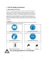
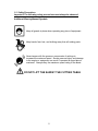
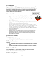
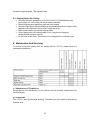
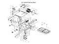
OWNERS
MANUAL
7” Table Top Tile Saw
MODEL:CTC701
FORM <<CTC701 rev 2/2010
WARRANTY
Norton warrants all products manufactured by it against defects in
workmanship or materials for a period of one (1) year from the date of
shipment to the customer.
The responsibility of Norton under this warranty is limited to
replacement or repair of defective parts at Norton's Stephenville,
Texas factory, or at a point designated by it, of such part as shall
appear to us upon inspection at such point, to have been defective in
material or workmanship, with expense for transportation borne by
the customer.
In no event shall Norton be liable for consequential or incidental
damages arising out of the failure of any product to operate properly.
Integral units such as gasoline engines, electric motors, batteries,
tires, transmissions, etc., are excluded from this warranty and are
subject to the prime manufacturer's warranty.
This warranty is in lieu of all other warranties, expressed or implied,
and all such other warranties are hereby disclaimed.
Important: Before placing equipment in operation, record the following
information.
MODEL:_________ SERIAL NO.___________
PURCHASE FROM: _____________________
ADDRESS: ____________________________
CITY_______ STATE ______ ZIP ________
TELEPHONE NO. ______________________
Before using this equipment, make sure that person using it
read and understand the instructions in this owner’s manual.
2
Table Of Contents
CONTENTS
I. CTC701 Safety Instructions
PAGE
4-9
1. Basic Safety Instructions
1.1 Symbols
1.2 Safety Precautions
1.3 Dust and Silica Warning
1.4 Safety instructions for working with the machine
10-12
2. Machine Description
2.2 Use of Machine
2.3 Layout
2.3 Technical Specifications
2.4 Items Includes With The CTC701
10
10-11
12
12
12-14
3. Assembly
3.1
3.2
3.3
3.4
3.5
3.6
4
4
5
6
7-9
13
13
13
13
13-14
Tool Assembly
Blade Installation
Guide-A-Cut Assembly
Electrical Connections
Starting The Machine
Water Cooling System
14
4. Transport And Storing
14
14
4.1 Securing For Transport
4.2 Long Period Of Inactivity
14-15
5. Operating the CTC701
5.1. Positioning The CTC701
5.1.2 Space Required For Operation And Maintenance
5.2 Cutting Methods
5.3 General Advice For Cutting
14
14
14-15
15
15-16
6 Maintenance And Servicing
15
15
16
6.1 Maintenance Of The Machine
6.2 Lubrication
6.3 Cleaning The CTC701
16
7. Trouble Shooting
16
16
7.1 Trouble Shooting Procedures
7.2 Trouble-Shooting Guide
17-19
8. Parts List Section
18-19
8.1 CTC701 Service Parts
Read Owners Manual Before Use
Safety Alert Symbol: Information Following This Symbol Is Very
Important.
Use Only Norton Diamond Blades
3
I. CTC701 Safety Instructions
1. Basic Safety Instructions
The CTC701 is exclusively designed for the cutting of ceramic tiles, porcelain tiles,
natural stone flooring materials, artificial stone flooring materials, and terracotta
materials up to 2-1/4” (57mm). Uses other than the manufacturer's instructions will
violate the machine’s warranty. The Saint-Gobain Abrasives, Inc. shall not be held
responsible for any resulting damage. Any risk shall be borne entirely by the user.
Observing the operating instructions and compliance with inspection and servicing
requirements shall also be considered as included under use in accordance with the
regulations.
1.1 Symbols
Important warnings and pieces of advice are indicated on the machine using symbols.
The following symbols are used on the machine:
You Are Responsible For Your Safety!!!
4
1.2 Safety Precautions
Important! The following safety precautions must always be observed.
Additional Warning/Hazard Symbols
Keep all guards in place when operating any piece of equipment
Keep hands, feet, hair, and clothing away from all rotating parts
Never tamper with the governor components of settings to
increase the maximum speed. Severe personal injury and damage
to the engine or equipment can result if operated at speed above
maximum. Always obey the maximum speed rating of the blade.
DO NOT LIFT THE SAW BY THE CUTTING TABLE
5
1.3 Dust and Silica Warning
Grinding/cutting/drilling of masonry, concrete, metal and other materials can
generate dust, mists and fumes containing chemicals known to cause serious or
fatal injury or illness, such as respiratory disease, cancer, birth defects or other
reproductive harm. If you are unfamiliar with the risks associated with the
particular process and/or material being cut or the composition of the tool being
used, review the material safety data sheet and/or consult your employer, the
material manufacturer/supplier, governmental agencies such as OSHA and
NIOSH and other sources on hazardous materials and make certain to comply
with all product warnings and instructions for the safe and effective use of the
material being cut. California and some other authorities, for instance, have
published lists of substances known to cause cancer, reproductive toxicity, or
other harmful effects.
Control dust, mist and fumes at the source where possible. In this regard use
good work practices and follow the recommendations of the
manufacturer/supplier, OSHA/NIOSH, and occupational and trade associations.
Water should be used for dust suppression when wet cutting is feasible. When
the hazards from inhalation of dust, mists and fumes cannot be eliminated
through engineering controls such as vacuum and/or water mist, the operator
and any bystanders should always wear a respirator approved by NIOSH/MSHA
for the material being cut.
Use Approved:
Eye Protection
Hearing
Protection
Respiratory
Protection
6
Head Protection
1.4 Safety instructions for working with the machine
Before Commencing Work:
• Know your CTC701 Tile Cutting machine! Read the Operator’s manual carefully.
Learn the operation, application and limitations, as well as the specific potential
hazards peculiar to this equipment and its usage.
• Before commencing work, make yourself familiar with the working environment at
the place of use. The working environment includes: obstacles in the area of
work and maneuver, the firmness of the floor, necessary protection at the site
relating to public thoroughfares and the availability of help in the event of
accidents.
• Keep the work area clean avoiding cluttered work areas.
• Consider the work area environment!
¾ Do not expose power tools to rain.
¾ Wear rubber boots to further insulate yourself from the machine.
¾ Mop up all excessive water around the work area before and after cutting.
¾ Keep the work area well lit.
• Keep visitors away. Do not let visitors contact tool or extension cord. All visitors
should be kept at a safe distance from the work area.
• Do not force the material into the blade.
• Place the machine on an even, firm and stable base!
• Check for correct mounting of the blade regularly.
• Immediately remove damaged or badly worn blades, as any damaged or badly
worn blade is a danger to the operator.
• The material to be cut must be held securely in place on the table to allow no
unexpected movement during cutting operation.
• Always cut with the blade guard in position.
• Only use Norton diamond blades with continuous rim with the machine! The use
of other tools can damage the machine and will void the warranty!
• Read the blades’ specifications carefully to choose the correct tool for your
application.
• Dress properly for the work being performed.
¾ Do not wear loose clothing or jewelry which can get caught in moving or
rotating parts.
¾ Rubber gloves and non-skid footwear is recommended when working
outside.
¾ Wear protective covering to contain long hair.
• Don’t overreach! Keep proper footing and balance at all times. The slippery
surface created during the drilling operation results in unstable footing.
• Use safety goggles or safety glasses that meet ANSI Z87.1-2003 safety
standards.
Electrical Safety Precautions:
• Always turn off the machine and disconnect it from the main source of electricity
before any work on the machine is done.
• Make sure that all electrical connections are secure and properly insolated to
eliminate contact of live wires with spray water or dampness.
• When the machine is used with water, it is IMPERATIVE that you properly
ground. Let a qualified electrician check in case of doubt.
7
•
•
•
•
•
•
•
•
•
•
Use only three-wire grounded extension cords suitable for use outdoors and of
sufficient gage to accommodate power requirements.
Ground the machine! The tile saw must be grounded while in use to protect the
operator from electric shock. The motor is equipped with a three prong
grounding type plug to fit the proper type receptacle. The green [or green &
yellow] conductor in the cord is grounding wire.
NEVER connect the ground green [or green & yellow] wire to a live terminal.
Replace frayed or damaged power and extension cords.
Don’t abuse the cord. Never carry the tool by the cord or yank the cord to
disconnect the plug from the receptacle.
ALWAYS disconnect the power before servicing or changing accessories or
Diamond Blades
ALWAYS make sure power switch is in “off” position before connecting the
machine to power.
ALWAYS check, to make sure wrenches are removed from the motor spindle
before connecting power or starting the tile saw.
In case of emergency, you can stop the machine by pushing on the front cover of
the switch.
In the event of the machine breaking down or stopping for no apparent reason,
switch off the main electricity supply, even in case of power supply failure. Only a
qualified electrician is allowed to investigate the trouble and remedy the fault.
8
1. Before mounting any blade on the saw, the blade should be inspected for
any damage which might have occurred during shipment, handling or
previous use.
2. The blade collars and arbors should be cleaned and examined for
damage before mounting the blade.
3. The blade must be properly fitted over the arbor with the relief side of the
collars facing the blade.
4. The blade shaft nut must be tightened securely against the outside blade
shaft collar.
5. The blade must be operated within the specified maximum operating
speed listed on the blade.
6. Fill the water pan with water.
7. The blade guard must be in place with the nose guard down and locked
when the saw is running.
8. The operator should wear safety glasses and any other appropriate
safety equipment.
9. When starting the saw, the operator should stand away and to the side of
the blade.
10. If for any reason the saw should stall in the cut, remove the material
from the blade. Check the outside blade shaft collar and nut for
tightness. Inspect the blade for damage before restarting the saw. Use
caution when resuming a cut. Be certain that the blade is in alignment
with the previous cut.
11. Do not force the blade into the cut by pushing the material into the
blade too fast.
You Are Responsible For Your Safety!!!
9
2. Machine Description
Any modification, which could lead to a change in the original characteristics of the
machine, may be done only by Saint-Gobain Abrasives who shall confirm that the
machine is still in conformity with the safety regulations.
The CTC701 Tile saw is designed for durability and high performance for onsite wet and
dry cutting operations of a wide range of tiles. As with all other Norton Clipper products,
the operator will immediately appreciate the attention given to detail and quality of
materials used in construction. The machine and its component parts are assembled to
high standards assuring long life and minimum maintenance.
2.2 Use of Machine
The machine is designed for wet and dry cutting of a large range of tiles. It is not
designed for cutting wood or metals.
2.3 Layout
6
2
5
4
1
3
Frame (1)
The frame is made of a strong plastic to ensure perfect rigidity. It supports the motor, the
cutting table and the switch.
Cutting Table (2)
Zink coated steel top for an excellent resistance to corrosion with engraved
measurements for precise guide-a-cut alignment (5).
10
Electrical Motor and Switch (3)
Motor with 1.07 HP (800W). The motor is designed to operate on 115-120 volts, 60 Hz,
single phase electrical circuits. Use a circuit with a 15 Amp circuit breaker for best
performance. The ON-OFF switch also serves as emergency stop.
Tilting Table (4)
The cutting table tilts to 45 ° for making miter cuts. To tilt the cutting table loosen the two
screws on the side and pivoting the table. The CTC701 has a built in gauge for precise
angle adjustments.
Guide-a-cut (5)
The guide-a-cut can be adjusted to the desired cutting width. It is locked using two
screws. The guide-a-cut is also adjustable for miter cuts.
Blade Guard (6)
The pivoting blade guard is designed to accept a 7” (177mm) diameter blade and offers
maximum operator protection and increased visibility of the work piece. The guard is
attached to the frame.
11
2.3 Technical Specifications
Technical Specifications
Product Number (UPC)
Blade Guard Capacity - in (mm)
Maximum Depth of Cut - in (mm)
Arbor Size - in (mm)
Blade Flange Diameter - in (mm)
Blade Shaft RPM
Maximum Material Size - in (mm)1
Rip Cut Size - in (mm) 1
Diagonal Size - in (mm) 1
Cut Depth - in (mm)
Cutting Table
Built In 45° Miter Cut
Cutting Table
Water Pump
Power Source
Motor/Engine Type
Maximum Horsepower
Voltage
Cycle*/Current/Phase
Full Load Amps
CTC701
70184630029
7" (177)
2-1/4" (57)
5/8"
3 (78)
2,990
-NA-NA-NA1-9/16" (40)
Steel
YES
Zinc Plated Steel
Blade Rotates In Water Pan
Electric
T.E.F.C.
1.07 HP
115 volt
60 Hz/AC/1
7 Amps
Saw Dimensions
Saw Length - in (mm)
Saw Width - in (mm)
Saw Height - in (mm)
Weight Crated - lbs (kg)
Weight – uncrated - lbs (kg)
Weight Of Machine With Water Pan Full
18.11" (460mm)
14.17" (360mm)
11-7/16" (290)
40 lbs (18 kg)
35 lbs (15.9 kg)
41 lbs (19 kg)
72 dB (A) (ISO EN 11201)
80 dB (A) (ISO EN 3744)
Sound pressure2
Sound power2
* = Data Provided by Motor/Engine Manufacturer, 1 = Open Table Top Design Allows Unlimited Material Sizes, 2) The sound measures
have been made following pr EN 12638, Annex A;
2.4 Items Includes With The CTC701
9
9
9
9
9
Carrying Case
Guide-A-Cut
Small Phillips Head Screw Driver
Blade Shaft Wrenches: 19mm Wrench and Spanner Wrench
Norton Continuous Rim Diamond Blade for Cutting Tile
3. Assembly
The machine is delivered fully equipped. It is ready for operation after assembling the
diamond blade, the blade guard and the guide-a-cut, and connection to the appropriate
power supply.
12
3.1 Tool Assembly
Only use NORTON CLIPPER continuous rim blades with a maximum diameter of 7”
(177mm) can be used with the CTC701. All tools used must be selected with regard to
their maximum permitted cutting speed for the machine’s maximum permitted rotation
speed. Before mounting a new blade into the machine, switch off the machine and
isolate it from the main source of electricity.
Plate Blade Cover
3.2 Installing The Blade
•
•
•
•
•
•
•
•
•
Loosen the two screws on the side of the plate blade cover with the
Phillips head screw driver and remove the plate blade cover.
Loosen the hexagonal nut which holds the removable outer flange on
the blade shaft with the 19mm wrench and use the spanner wrench to
lock the flange.
Remove the outer flange.
Loosen the two screws holding the blade guard support and remove it from the
machine.
Clean the flanges and blade shaft and inspect for wear.
Mount the blade on the flange ensuring that the direction of rotation is correct
(check with the arrow on the blade guard for blade shaft rotational direction and
match the blade rotational direction to the machine). Installing the blade
incorrectly can cause poor cutting performance and reduce the life of the blade.
Replace outer blade flange.
Tighten hexagonal nut.
Retighten the two screws holding the front cover, and reassemble the blade
guard support on the table. The blade bore must correspond exactly to the
diameter of the blade shaft. Cracked or damaged bore is dangerous for the
operator and for the machine.
3.3 Guide-A-Cut Assembly
To assemble the guide a cut:
• Put the guide a cut on the table.
• Use the handle on the side of the guide-a-cut to pinch it on the table
3.4 Electrical Connections
Check that,
• The voltage/phase supply corresponds to the information indicated on the motor
plate.
• Available power supply must have ground connection in conformity with safety
regulations.
3.5 Starting The Machine
Press the green button to start the machine. Press on the red button to stop the
machine. The red button is also the emergency switch.
3.6 Water Cooling System
13
•
•
•
•
Fill the water pan with clean water up to 3/16” (5mm) from the upper edge of the
water tray.
Ensure that water is delivered adequately to both sides of the blade, as
insufficient water supply may result in premature failure of the diamond blade and
is not covered by any warranty.
Always make sure that there is enough water in the pan and refill if necessary.
In case of frost, empty the water cooling system from its water.
4. Transport And Storing
4.1 Securing For Transport
Before transporting the machine, always remove the blade and empty the water pan.
4.2 Long Period Of Inactivity
If the machine is not going to be used for a long period, please take the following
measures:
•
•
Completely clean the machine
Empty the water pan. The storage site must be clean, dry and at a constant
temperature.
5. Operating the CTC701
5.1. Positioning The CTC701
•
•
•
•
•
•
Remove anything from the area, which might hinder the working procedure!
Make sure the site is sufficiently well lit!
Observe all proper conditions for connecting to power supplies!
Place electric cables in so that the cable will not damage by the device and that
the cable will not contact water!
Make sure you have a continual adequate view of the working area so you can
intervene in the working process at any time!
Keep other staff out of the area, so you can work securely.
5.1.2 Space Required For Operation And Maintenance
Leave 6-1/2 feet (2 m) around the machine for usage and maintenance of the CTC701.
5.2 Cutting Methods
To use the machine correctly, you must face it with the two hands on the tile to be cut,
pushing the tile against the blade. Always keep your hands away from the moving blade.
To set the guide-a-cut at the desired cutting width, release it, and use the two scales on
14
the table to align the guide. Then tighten it back.
5.3 General Advice For Cutting
•
•
•
•
•
•
Only tiles with max. dimensions of 15-3/4”x15-3/4”x1/4” (400x400x6mm) and
max. weight of 6-1/2 lbs (3kg) can be cut with the machine.
Before beginning work make sure tools are firmly seated!
Select the right Norton Diamond Blade as recommended by Norton Clipper which
depends on the material to be cut, and if cutting wet or dry.
Make sure the water tray contains enough water.
Set the guide-a-cut to the desired width of cut, using the two engraved
measurements to align it correctly.
Do not force on the motor. This machine is not designed for a continuous use.
6. Maintenance And Servicing
To ensure a long-term quality from the cutting with the CTC701, please follow the
maintenance plan below:
6.1 Maintenance Of The Machine
Always perform the maintenance of the machine with the machine isolated from the
electrical supply.
6.2 Lubrication
The CTC701 uses life-lubricated bearings. Therefore, you don’t need to lubricate the
machine at all.
15
6.3 Cleaning of the machine
Your machine will last longer if you clean it thoroughly after each day of work, especially
water pan, motor and blade flange. To clean disconnect the machine from the power
source and wipe down the CTC701 with a damp cloth.
7. Trouble Shooting
7.1 Trouble Shooting Procedures
Should any fault occur during the use of the machine, turn it off, and isolate it from the
electrical supply. Any works dealing with the electrical system or supply of the machine
can only be carried out by a qualified electrician.
7.2 Trouble-Shooting Guide
Trouble
Motor Is Not Running
No Water On The Blade
Cuts Are Not Straight
Blade Is Not Cutting The
Material
Material Is Chipping
Possible Source
No Electricity
Resolution
Check The Electrical Supply
(Circuit Breaker For Example)
Extension Cable Is Too Small
Of Gauge Or Too Long
Change Extension Cable
Do Not Exceed A 50’ 10AWG
Defective Extension Cable
Change Extension Cable
Defective Switch
CAUTION : Can Only Be
Solved By Qualified Electrician
Defective Motor
Change Motor Or Contact
Motor Manufacturer
Not Enough Water In The Pan
Guide-A-Cut Is Not Properly
Adjusted
Incorrect Blade Specification
For Material Being Cut
Refill The Water Pan
Check And Realign The GuideA-Cut
Replace Blade With The
Correct Norton Diamond Blade
Specification.
Slow Feed Speed Of Tile
Replace Blade With One Of
The Correct Specification
Too Fast Of Cut Speed
Incorrect Blade Specification
16
8. Parts List Section
Ordering Information
1. List model number and serial number of machine.
2. List part number and serial number of part not the item number.
3. Wherever alternate parts are shown due to product improvement, inspect the
part you have and provide additional description as necessary.
4. Specify mode of shipping desired, such as, parcel post, truck, U.P.S., best way,
etc.
Clear instructions will avoid problems and faulty deliveries. If not sure, please send us
the defective part. In the case of a warranty claim, the part may be needed to be
returned for evaluation.
Warranty can be claimed and technical support obtained from your local distributor
where machines, spare parts and Norton Diamond Blades can be purchased as well:
For the nearest Clipper distributor call 1-800-554-8003
Common Replacement Parts
Description
Part Number
Tile Saw Blade
See Distributor or Call Norton Clipper For Assistance In
Selecting The Correct Norton Blade For Your Application
COLLAR BLADE TIGHT
COLLAR BLADE LOOSE
NUT M12 FLANGE (BLADE SHAFT NUT)
WRENCH SPANNER CTC701
WRENCH 19MM OPEN END
SCREW DRIVER PHILLIPS
CARRYING CASE CTC701
-NA-
243056
243058
243059
243078
243079
243080
243081
NOTE: All Parts Are Sold As Individual (each) Unless Noted Otherwise
Use Only Norton Diamond Blades.
Contact your local Norton Clipper
Distributor or Norton Clipper at 1-800-554-8003 for the best blade for the application.
17
8.1 CTC701 Service Parts
18
8.1 CTC701 Service Parts
POS
1
2
3
4
5
6
7
8
9
10
11
12
13
14
15
16
17
18
19
20
21
22
23
24
25
26
27
28
29
30
31
32
33
34
35
36
37
38
39
40
41
42
43
44
45
46
47
48
Part#
243000
243001
243002
243003
243004
243005
243006
243007
235136
300279
243008
243009
243010
243011
243012
243013
243014
243015
243016
243017
243018
243019
243020
243021
243022
243023
243024
243025
243026
243027
243028
243029
243030
243031
243032
243033
243034
243035
243036
243037
243038
243039
243040
243041
243042
243043
243044
243045
UPC#
70184600850
70184600756
00310361101
00310361102
00310301207
00310361104
70184641853
Description
SCR 2.9 X 13 PHILLIPS HEAD
GASKET FOR POWER CABLE
COVER FOR CAPACITOR BOX
CABLE CLAMP
GASKET CAPACITOR BOX
SCR 4 X 9
SECURING STRAP FOR CAPACITOR
SCR 3.5 X 12
NUT M6 DIN985 LOCK
WASHER LOCK M6 DIN127B
BRACKET FRONT SUPPORTING
SCR M4 X 8 0.7 DIN933
KNOB
AXLE SHAFT
SCR M6 X 16 1.0 DIN933
SPRING
SECURING STRAP
CABLE INNER
FOOT RUBBER
SWITCH POWER PUSH BUTTON CTC701
GASKET SWITCH CTC701
BRACKET SWITCH CTC701
CABLE GUIDE
POWER CABLE CTC701
SECURING STRAP POWER CABLE CTC701
SCR M4 X 13
PLATE HANDLE SUPPORT CTC701
BRACKET HANDLE CTC701
HANDLE CTC701
BRACKET SWITCH SECURING CTC701
GASKET SWITCH BOX CTC701
COVER SWITCH BOX CTC701
NUT FIXING
PIN M5 X 32 ROLL
SECURING PLATE GUIDE-A-CUT CTC701
PIN M4 X 18 ROLL
LEVER GUIDE-A-CUT CTC701
HINGE GUIDE-A-CUT CTC701
SHAFT GUIDE-A-CUT CTC701
SPRING GUIDE-A-CUT CTC701
SLIDE GUIDE-A-CUT CTC701
ARM GUIDE-A-CUT CTC701
SCR M4 X 6 0.7 DIN933
SLIDING SUPPORT GUIDE-A-CUT CTC701
ANGLE GUIDE GUIDE-A-CUT CTC701
KNOB FOR GUIDE-A-CUT CTC701
SCR M2.5 X 6
WASHER M3 FLAT
19
QTY REQ
6
1
1
3
1
5
1
6
3
5
1
7
2
2
2
2
2
1
4
1
1
1
1
1
6
7
1
1
1
1
1
1
1
1
1
1
1
1
6
1
1
1
2
1
1
1
1
1
Type(*)
S
W
S
S
W
S
W
S
S
S
S
S
S
S
S
W
S
W
W
W
W
S
W
W
S
S
S
S
S
S
W
S
S
S
S
S
S
S
S
W
S
S
S
W
W
S
S
S
POS
49
50
51
52
53
54
Part#
243046
243047
243048
243049
243050
243051
55
56
57
58
59
60
243052
243053
243054
243055
243056
-NA-
61
62
63
64
65
66
67
68
69
70
71
72
73
74
75
76
77
78
79
80
81
82
83
84
85
86
87
88
89
90
243057
243058
243059
243060
243061
243062
243063
243064
235104
243065
243066
243067
243068
235103A
243069
243070
235065
502088
243071
243072
243073
243074
224237
27539
243075
243076
243077
243078
243079
243080
UPC#
00310340199
00310340200
Call for
assistance
00310361134
70184600873
00310340216
70184600881
70184641855
70184641854
70184600790
70184631179
70184665412
70184600585
00310361166
Description
SLIDE W/SLOTS GUIDE-A-CUT CTC701
NUT M4 DIN985 LOCK
CUTTING TABLE CTC701
BLADE GUARD LEFT SIDE CTC701
SCR M6 x 25 1.0 CARRIAGE
BRACKET BLADE GUARD SUPPORT
CTC701
SUPPORT BLADE GUARD CTC701
BLADE GUARD RIGHT SIDE CTC701
SCR 2.6 X 10
MOT 1.07 HP (800W) 115v/60/1 CTC701
COLLAR BLADE TIGHT
BLADE
COLLAR BLADE LOOSE
NUT M12 FLANGE
GASKET POWER CABLE INPUT
RUBBER STOP
PLATE MOTOR COVER CTC701
BRACKET BACK SUPPORT CTC701
WASHER M4 LOCK
GROUND STRAP CTC701
WASHER M4 DIN125 FLAT
WASHER M4 FLAT
WASHER M4 LOCK
NUT M4 DIN985 LOCK
PLATE BLADE COVER CTC701
SCR M5 X 12 0.8 DIN933
DRAIN PLUG CTC701
WATER PAN CTC701
WASHER M5 DIN125 FLAT
WASHER M5 LOCK DIN127B
SCR M5 X 18 0.8 DIN7985 PHILLIPS HEAD
TERMINAL BLOCK CTC701
CAPACITOR CTC701
SCALE CUTTING TABLE CTC701
SCR M6 X 20 1.0 DIN933
WASHER M6 DIN 125 FLAT
GASKET POWER CABLE OUTPUT CTC701
RUBBER WASHER
WRENCH SPANNER CTC701
WRENCH 19MM OPEN END
SCREW DRIVER PHILLIPS
CARRYING CASE CTC701
QTY REQ
1
1
1
1
1
1
1
1
4
1
1
1
1
1
2
3
1
1
1
1
1
1
1
2
1
2
1
1
4
1
4
1
1
2
1
1
1
1
1
1
1
(*): S = Spare part, W = Wear part
Wear parts are worn out through normal use of the machine. The wear period depends a lot on
the intensity of use of the machine. Wear parts must be serviced, used and eventually changed
following the indications of the manufacturer. Any wear due to normal use of the machine will not
be considered as a case of warranty. Genuine Norton Clipper replacement parts should always
be used. All items are sold as each unless otherwise noted.
20
Type(*)
S
S
S
S
S
S
S
S
S
S
S
W
S
S
S
W
S
S
S
W
S
S
S
S
S
S
W
S
S
S
S
W
W
S
S
S
W
S
S
S
S
S
NOTES:
21
Saint-Gobain Abrasives
2770 West Washington
Stephenville, TX 76401
Phone: 800-554-8003
Fax: 800-443-1092
22