1
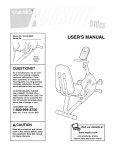
USER'S MANUAL
Model No. 831.283500
Serial No.
Write the serial number in the
space above for future reference.
_r'_'_ Serial Number
Decal
F- xIE_
EQUIPMENT
R
C
I S
IE_
HELPLINE!
1-800-736-6879
SEARS, ROEBUCK AND CO.,
HOFFMAN ESTATES, IL 60179
www.weslo,com
new products, prizes,
fitness tips, and much more!
TABLE OF CONTENTS
IMPORTANT PRECAUTIONS .............................................................
BEFORE YOU BEGIN ...................................................................
ASSEMBLY ...........................................................................
HOW TO USE THE ELLIPTICAL CROSSTRAINER .............................................
MAINTENANCE AND TROUBLESHOOTING .................................................
CONDITIONING GUIDELINES ............................................................
PART LIST ...........................................................................
EXPLODED DRAWING .................................................................
HOW TO ORDER REPLACEMENT PARTS ...........................................
LIMITED WARRANTY ...........................................................
2
3
4
5
9
11
13
14
15
Back Cover
Back Cover
BEFORE YOU BEGIN
Congratulations for selecting the new WESLO ®
MOMENTUM 750 elliptical crosstrainer. The MOMENTUM 750 elliptical crosstrainer is an incrediblysmooth
exerciser that moves your feet in a natural elliptical
path, minimizing the impact on your knees and
ankles, And the unique MOMENTUM 750 features
adjustable resistance and a simple-to-use console to
help you get the most from your exercise.
HELPLINE at 1-800-736-6879, Monday through
Saturday, 7 a.m. until 7 p.m. Central Time (excluding
holidays). To help us assist you, please note the product model number and serial number before calling.
The model number is 831.283500, The serial number
is found on a decal attached to the elliptical
crosstrainer (see the front cover of this manual for the
location of the decal).
For your benefit, read this manual carefully before
using the elliptical crosstrainer, If you have questions after reading the manual, please call our toll-free
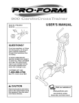
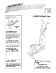
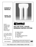
Before reading further, please familiarize yourself with
the parts that are labeled in the drawing below.
Handlebar
Water Bottle Holder*
Console
Resistance Knob
FRONT
BACK
Pedal Arm
Pedal Disk
Pedal
*No water bottle is included
4
ASSEMBLY
Assembly requires two persons. Place all parts of the elliptical crosstrainer in a cleared area and remove the
packing materials. Do not dispose of the packing materials until assembly is completed. In addition to the
included allen wrenches, assembly requires a phillips screwdriver _,
an adjustable
wrench _,
and a rubber mallet (
(_.
As you assemble the elliptical crosstrainer, use the drawings below to identify the small parts used in assembly.
The number in parenthesis below each drawing refers to the key number of the part, from the PART LIST on
page 14. The second number refers to the quantity used in assembly. Note: Some small parts may have been
pre-assembled for shipping. If a part is not in the parts bag, check to see if it has been pre-assembled.
M6 Nylon
Locknut (27)-4
M 10
Washer (35)-2
M8 Nylon
Locknut (38)-4
M4 x 16ram
Screw {42)-4
M6
Washer (25)-4
M10 Nylon
Locknut (33)-6
M6 x 54ram Flat Head
Bolt (36)-4
M8 x 38mm Button Bolt (50)-4
M10 x 25mm
Patch Screw (22)-2
Pedal Arm Bolt Set (40)-2
M10 x 66mm Button Bolt (48)-2
1. Identify the Front Stabilizer (10), which is narrower than
the Rear Stabilizer (not shown). While another person
lifts the front of the Frame (1), attach the Front
Stabilizer to the Frame with two M10 x 75mm Carriage
Bolts (34) and two M10 Nylon Locknuts (33).
M10 Split
Washer (59)-2
M10 x 75mm Carriage Bolt (34)-4
1
34
10
33
2. WhileanotherpersonliftsthebackoftheFrame(1),
attachtheRearStabilizer
(28)totheFramewithtwo
MIOx75mmCarriage
Bolts(34)andtwoMIONylon
Locknuts
(33).
33 _
lj-"S
3. TheConsole(23)requires
three"AA"batteries
(not
included);
alkalinebatteries
arerecommended.
Insert
threebatteries
intothebatterycompartment.
Make
3
_-Batteries
sure that the batteries are oriented as shown by
the diagram inside the battery compartment.
/'
4. While another person holds the Console (23) near the
Upright (2), connect the console wire to the Upper
Wire (44). Insert the console wire and the Upper Wire
into the Upright.
4
Console Wire _3,
Attach the Console (23) to the Upright (2) with four M4
x 16ram Screws (42). Be careful to avoid pinching
the console wire or the Upper Wire (44).
44 _ ,-_,_
i
/
Turn the Resistance Knob (63) counterclockwise
the lowest setting before continuing to the next
step.
•
/e
p
,
I "t
to
42"--"
5. While another person holds the Upright (2) near the
Frame (1), connect the Upper Wire (44) to the Reed
Switch Wire (53).
/_
5
/
_
2
_
59
33__-_
,_._=.//
--'_
"_r-_
_'
- _
/_ _,,
Next, connect the Resistance Cable (63) to the Lower
Cable (55) in the following way:
• Refer to drawing A. Pull up on the metal bracket on
the Lower Cable (55), and insert the tip of the
Resistance Cable (63) into the wire clip inside of the
metal bracket.
Makesurethat
the wires and
48 cables do not
get pinched
end damaged
during this
• Refer to drawing B. Firmly pull the Resistance Cable
(63) and slide it into the metal bracket on the Lower
Cable (55) as shown.
• Refer to drawing C. Using pliers, squeeze together
the prongs on the upper end of the metal bracket.
Push the excess cable and wire down into the Frame
(1). Slide the Upright (2) onto the Frame. Be careful
not to pinch the wires or cables. Secure the Upright
to the Frame with two M10 x 66mm Button Bolts (48),
two M10 Split Washers (59), and two M10 Nylon
Locknuts (33). Do not tighten the Button Bolts yet.
A
Metal
_,
Bracket _
!B
!!
i.i
!C
I
55_
t'-
6. identify the Left Handlebar (6), which is marked with a
sticker. Insert the Left Handlebar into one of the
Handlebar Arms (5); make sure that the Handlebar
Arm is turned so the hexagonal holes are on the
indicated side, Attach the Left Handlebar to the
Handlebar Arm with two M8 x 38mm ButtonBolts (50)
and two M8 Nylon Locknuts(38). Make sure that the
Nylon Locknuts are inside of the hexagonal holes.
Do not fully tighten the Button Bolts yet.
6
Apply a small amount of the included grease to the left
axle on the Upright (2).
49
Make sure that there are two Small Handlebar
Bushings (49) in the Left Handlebar (6). Slide a
Handlebar Spacer (47) and the Left Handlebar onto the
left axle on the Upright (2) as shown. Make sure that the
Handlebar Spacer is turned so the curved side is facing the Upright. Tap an Axle Cap (14) onto the axle.
47
Repeat this step to assemble the Right Handlebar (8)
and the other Handlebar Arm (5).
7. Identify the Left Pedal Arm (11). Attach a Pedal (13) to
the Left Pedal Arm with two M6 x 54mm Flat Head
Bolts (36), two M6 Washers (25), and two M6 Nylon
Locknuts (27) as shown.
36
13
Attach the other Pedal to the Right Pedal Arm (not
shown) in the same way.
11
8. Apply a small amount of grease to the axle on the left
Disc Crossbar (16). Slide the Left Pedal Arm (11) onto
the axle. Slide an M10 Washer (35) onto an M10 x
25mm Patch Screw (22), and tighten the Patch Screw
into the axle.
Next, hold the lower end of the left Handlebar Arm (5)
inside of the bracket on the Left Pedal Arm (11). Apply
grease to a Pedal Arm Bolt Set (40). Attach the Left
Pedal Arm to the left Handlebar Arm with the Bolt Set.
Do not overtighten the Bolt Set; the Handlebar Arm
must pivot freely.
Attach the Right Pedal Arm (not shown) to the right
side of the elliptical crosstrainer in the same way.
8
Grease
Refer to step 5. Tighten the M10 x 66mm Button Bolts
(48) in the Upright (2).
Refer to step 6. Tighten the M8 x 38mm Button Bolts
(50) in the Handlebar Arms (5).
40 11
22
35
9. Make sure that ell parts of the elliptical crosstrainer are properly tightened, Note: Some hardware may
be left over after assembly is completed. To protect the floor or carpet from damage, place a mat under the
elliptical cresstrainer.
8
HOW TO USE THE ELLIPTICAL
HOW TO EXERCISE ON THE ELLIPTICAL
CROSSTRAINER
To mount the elliptical crosstrainer, hold the handlebars
and step onto the pedal that is in the lowest position.
Then, step onto the other pedal. Push the pedals until
they begin to move with a continuous motion. Note:
The pedal disks can turn in either direction. It is
recommended that you move the pedal disks in
the direction shown by the arrow; however, for
variety, you may turn the pedal disks in the opposite direction.
CROSSTRAINER
To dismount the elliptical crosstrainer, wait until the
pedals come to a complete stop. Note; The elliptical
crosstrainer does not have a free wheel; the pedals will continue to move until the flywheel stops.
When the pedals are stationary, step off the highest
pedal first. Then, step off the lowest pedal.
HOW TO ADJUST THE PEDALING RESISTANCE
As you exercise,
you can adjust the
resistance of the
pedals with the
resistance knob on
the upright. To
increase the resistance, turn the
knob clockwise; to
decrease the resistance, turn the
knob counterclockwise.
2. Select one of the modes:
FEATURES OF THE CONSOLE
The easy-to-use console features five modes that provide instant exercise feedback during your workouts.
The modes are described below.
Scan mode-Mode Indicators
When the power
is turned on, the
scan mode will be
selected automatically. A mode indicator will appear
_CAN
CALORI_S_
below the word
"SCAN" to show
that the scan
mode is selected,
and a second
mode indicator will show which mode is currently
displayed. Note: If you have selected a different
mode, repeatedly press the Mode button to reselect the scan mode.
!s 81
Speed, time, distance, or calorie
mode---To select
one of these
modes for continuous display,
repeatedly press
the Mode button.
The mode indicators will show
which mode is selected. Make sure there is not a
mode indicator below the word "SCAN."
dZ'ME"l
tO'S
Speed--This mode displays your pedaling speed, in
miles per hour or kilometers per hour.
Time--This mode displays the elapsed time. Note: If
you stop pedaling for a few seconds, the time mode
will pause.
Note: The console can display speed and distance in either miles or kilometers. To change
the unit of measurement, press the On/Reset
button for about five seconds. The letters mph or
km/h will appear in the display to show which unitof
measurement is selected. When the batteries are
replaced, it may be necessary to reselect the
desired unit of measurement.
Distance_This mode displays the distance you have
pedaled, in miles or kilometers.
Calorie--This mode displays the approximate number
of calories you have burned.
Scan--This mode displays the speed, time, distance,
and calorie modes, for a few seconds each, in a
repeating cycle.
3. To reset the display at any time, press the
On/Reset button.
HOW TO OPERATE THE CONSOLE
4. To turn off the power, simply wait for a few minutes.
The console has an "auto-off" feature. If the
Make sure there are batteries in the console (see
BATTERY REPLACEMENT on page 11). If there is a
thin sheet of clear plastic on the console, remove it.
pedals are not moved and the console buttons
are not pressed for a few minutes, the power
will turn off automatically to save the batteries.
Follow the steps below to operate the console.
1. To turn on the power, press the On/Reset button or
begin pedaling. The entire display will briefly
appear; the console will then be ready for use.
tn
MAINTENANCE
AND TROUBLESHOOTING
Inspect and tighten all parts of the elliptical crosstrainer
regularly. Replace any worn parts immediately.
To clean the elliptical crosstrainer, use a damp cloth
and a small amount of mild soap. Important: Keep
liquids away from the console, place only a sealed
water bottle in the water bottle holder, and keep
the console out of direct sunlight. During storage,
remove the batteries from the console.
Refer to the drawing below and locate the Reed Switch
(53). Loosen, but do net remove, the indicated M4 x
16ram Screw (42). Slide the Reed Switch slightly
toward or away from the Magnet (58) on the flywheel
Retighten the Screw. Turn the left Pedal Disc (15) for a
moment. Repeat until the console displays correct
feedback. When the Reed Switch is correctly adjusted,
reattach the Left Side Shield (3) and the Left Pedal
Arm (11).
BATTERY REPLACEMENT
If the console display becomes dim, the batteries
should be replaced; most console problems are the
result of low batteries. To replace the batteries, refer
to step 4 on page 6 and remove the console from the
upright. Next, refer to step 3 on page 6 and insert
three batteries into the console, Reattach the console
to the upright, being careful not to pinch the wires.
HOW TO ADJUST THE REED SWITCH
HOW TO ADJUST THE DRIVE BELT
If the console does not display correct feedback, the
reed switch should be adjusted, To adjust the reed
switch, you must remove the Left Pedal Arm (11) and
the Left Side Shield (3).
If the pedals slip while you are pedaling, even when
the resistance is adjusted to the highest setting, the
Drive Belt (19) may need to be adjusted. To adjust the
Drive Belt, you must first remove the left side shield,
Refer to HOW TO ADJUST THE REED SWITCH at
the left and remove the left side shield.
56
3
Next, loosen the
M8 x 22mm Flat
Head Screw
(41) and turn
the Idler
Adjustment Bolt
(62) until the
Drive Belt (19)
is tight. When
the Drive Belt is
tight, tighten the
Flat Head
Screw. Reattach
the left side shield.
11
42
22
Remove the Pedal Arm Bolt Set (40), the M10 x
25ram Patch Screw (22), and the M10 Washer (35)
from the Left Pedal Arm (11). Remove the Left Pedal
Arm. Next, remove the two M4 x 25mm Screws (56)
and the four M4 x 16mm Screws (42) from the Left
Side Shield (3).
11
HOW TO ADJUST THE RESISTANCE STRAP
If the resistance knob is turned to the highest setting
and there is not enough pedaling resistance, the
resistance strap can be adjusted. To adjust the resistance strap, first remove the left side shield (see HOW
TO ADJUST THE REED SWITCH on page 11).
Next, turn the resistance knob to the lowest setting.
Open the Strap Clamp (26) and pull the end of the
Resistance Strap (18) downward slightly. Close the
Strap Clamp and turn the Flywheel (17) to make sure
that there is not too much resistance.
When the resistance strap is properly adjusted, reattach the left side shield and the left pedal arm.
CONDITIONING GUIDELINES
The following guidelines will help you to plan your
exercise program. Remember that proper nutrition
and adequate rest are essential for successful results.
Aerobic Exercise
If your goal is to strengthen your cardiovascular system, your exercise must be "aerobic." Aerobic exercise is activity that requires large amounts of oxygen
for prolonged periods of time. This increases the
demand on the heart to pump blood to the muscles,
and on the lungs to oxygenate the blood. For aerobic
exercise, adjust the intensity of your exercise until
your heart rate is near the highest number in your
training zone.
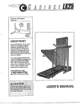
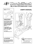
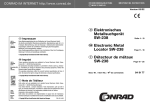
HOW TO MEASURE YOUR HEART RATE
EXERCISE INTENSITY
Whether your goal is to burn fat or to strengthen your
cardiovascular system, the key to achieving the
desired results is to exercise with the proper intensity.
The proper intensity level can be found by using your
heart rate as a guide. The chart below shows recommended heart rates for fat burning, maximum fat
burning, and cardiovascular (aerobic) exercise.
Exercise for at least
four minutes. Then,
stop exemising and
place two fingers on
your wrist as shown.
Take a six-second
heartbeat count, and
multiply the result by
10 to find your heart
rate. For example, if your six-second heartbeat count
is 14, your heart rate is 140 beats per minute. (A sixsecond count is used because your heart rate will
drop rapidly when you stop exercising.)
165
155
145
140
130
125
115
145
138
130
125
118
120
103
125
120
115
110
205
95
90
WORKOUT
20
30
40
50
60
70
80
Each workout should include the following three parts:
To find the proper heart rate for you, first find your age
at the bottom line of the chart (ages are rounded off to
the nearest ten years). Next, find the three numbers
above your age. The three numbers are your "training
zone." The lowest number is the recommended heart
rate for fat burning; the middle number is the recommended heart rate for maximum fat burning; the highest number is the recommended heart rate for aerobic
exercise.
Fat Burning
To burn fat effectively, you must exercise at a relatively low intensitylevel for a sustained period of time.
During the first few minutes of exercise, your body
uses easily accessible carbohydrate calories for energy. Only after the first few minutes of exercise does
your body begin to use stored fat calories for energy.
To burn fat, adjust the intensity of your exercise until
your heart rate is between the lower two numbers in
your training zone as you exercise.
GUIDELINES
A warm-up, consisting of 5 to 10 minutes of stretching
and light exercise. A proper warm-up increases your
body temperature, heart rate, and circulation in preparation for exercise.
Training zone exercise, consisting of 20 to 30 minutes of exercising with your heart rate in your training
zone. Note: During the first few weeks of your exercise program, do not keep your heart rate in your
training zone for longer than 20 minutes.
A cool-down, with 5 to 10 minutes of stretching. This
wilt increase the flexibility of your muscles and wilt
help to prevent post-exercise problems.
EXERCISE FREQUENCY
To maintain or improve your condition, plan three workouts each week, with at least one day of rest between
workouts. After a few months of regurar exercise, you
may complete up to five workouts each week, if
desired. The key to success is make exercise a regular and enjoyable part of your everyday life.
PART LIST--Model
Key No. Qty.
1
2
3
4
5
6
7
8
9
10
11
12
13
14
15
16
17
18
19
20
21
22
23
24
25
26
27
28
29
30
31
32
33
1
1
1
1
2
1
1
1
1
1
1
1
2
2
2
2
1
1
1
1
4
2
1
2
4
1
4
1
2
2
2
1
7
No. 831.283500
Description
R0802A
Key No. Qty.
Frame
Upright
Left Side Shield
Right Side Shield
Handlebar Arm
Left Handlebar
Idler Assembly
Right Handlebar
Hook
Front Stabilizer
Left Pedal Arm
Right Pedal Arm
Pedal
Axle Cap
Pedal Disc
Disc Crossbar
Flywheel
Resistance Strap
Drive Belt
Cable Clamp
Endcap
M10 x 25ram Patch Screw
Console
Handgrip
M6 Washer
Strap Clamp
M6 Nylon Locknut
Rear Stabilizer
Flywheel Beadng
Large Snap Ring
Large Bearing
Pedal Axle
M10 Nylon Locknut
34
35
36
37
38
39
40
41
42
44
45
46
47
48
49
50
51
52
53
54
55
56
57
58
59
60
61
62
63
#
#
#
4
2
4
4
5
2
2
1
15
1
1
2
2
2
4
4
8
1
1
1
1
2
1
1
2
4
2
1
1
1
1
1
Description
M10 x 75mm Carriage Bolt
M10 Washer
M6 x 54mm Flat Head Bolt
Pedal Arm Bushing
M8 Nylon Locknut
M10 Washer
Pedal Arm Bolt Set
M8 x 22mm Flat Head Screw
M4 x 16mm Screw
Upper Wire
Resistance Control/Cable
Handlebar Cap
Handlebar Spacer
M10 x 66mm Button Bolt
Small Handlebar Bushing
M8 x 38mm Button Bolt
M6 x 35mm Screw
M4 x 16mm Flat Head Screw
Reed Switch/Wire
Cable Clamp
Lower Cable
M4 x 25ram Screw
M10 Flat Head Bolt
Magnet
M10 Split Washer
Large Handlebar Bushing
5/16" x 25.4mm Hex Bolt
Idler Adjustment Bolt
Resistance Knob/Cable
Allen Wrench
Grease
User's Manual
Note: # indicates a non-illustrated part. Specifications are subject to change without notice.
14
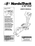
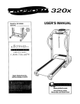
EXPLODED
DRAWING--Model
No. 831.283500
RO802A
42
42
3
46
\
42
4O
49
14
13
.;
22
6O
37
18
6O
17
6O
39
37
51
20
34
21
51
13
15
21
. 11
32
40
3O
7
62
15
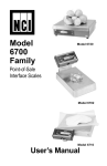
SEARS
The model number and serial number of your WESLO ®
MOMENTUM 750 elliptical crosstrainer are listed on a decal
attached to the frame. See the front cover of this manual to find
the location of the decal.
Model No. 831.283500
QUESTIONS?
If you find that:
• you need help assembling or
operating the WESLO ®MOMENTUM 750 elliptical crosstrainer
All replacement parts are available for immediate purchase or
special order when you visit your nearest SEARS Service
Center. To request service or to order parts by telephone, call
the toll-free numbers listed at the left.
• a part is missing
When requesting help or service, or ordering parts, please be
prepared to provide the following information:
• or you need to schedule repair
service
• The NAME of the product (WESLO ® MOMENTUM 750 elliptical crosstrainer)
call our toll-free HELPLINE
• The MODEL NUMBER of the product (831.283500)
1-800-736-6879
Monday-Saturday, 7 am-7 pm
Central Time (excluding holidays)
• The KEY NUMBER OF THE PART (see page 15)
• The DESCRIPTION OF THE PART (see page 14)
REPLACEMENT
PARTS
If parts become worn and need
to be replaced, call the following
toll-free number
1-800-FON-PART
(1-800-366-7278)
FULL 90 DAY WARRANTY
For 90 days from the date of purchase, if failure occurs due to defect in material or workmanship in this
SEARS ELLIPTICAL EXERCISER, contact the nearest SEARS Service Center throughout the United
States and SEARS will repair or replace the ELLIPTICAL EXERCISER, free of charge.
This warranty does not apply when the ELLIPTICAL EXERCISER is used commercially or for rental purposes.
This warranty gives you specific legal rights, and you may also have other rights which vary from state
to state.
SEARS, ROEBUCK AND CO., DEPT. 817WA, HOFFMAN ESTATES, IL 60179
Part No. 189689 R0802A
Printed in China © 2002 ICON HeaLth & Fitness, Inc.