1
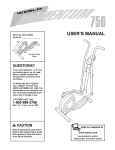
Model No. PFEL45012
Serial No.
USER'S MANUAL
Serial
Number
Decal
QUESTIONS?
If you have questions, or if there
are missing parts, we will guarantee complete satisfaction
through direct assistance from
our factory.
TO AVOID UNNECESSARY
DELAYS, PLEASE CALL DIRECT
TO OUR TOLL-FREE CUSTOMER
HOT LINE. The trained technicians on our customer hot line
will provide immediate assistance, free of charge to you.
CUSTOMER
HOT LINE:
1-800-999-3756
Mon.-Fri.,
6 a.m.-6 p.m. MST
CAUTION
Visit our website at
Read all precautions and instructions in this manual before using
this equipment. Keep this manual for future reference.
www.proform.com
new products, prizes,
fitness tips, and much more!
TABLE OF CONTENTS
IMPORTANT PRECAUTIONS
.............................................................
BEFORE YOU BEGIN ...................................................................
ASSEMBLY ...........................................................................
HOW TO USE THE ELLIPTICAL CROSSTRAINER
.............................................
MAINTENANCE AND TROUBLESHOOTING
.................................................
CONDITIONING GUIDELINES ............................................................
PART LIST ...........................................................................
EXPLODED DRAWING .................................................................
HOW TO ORDER REPLACEMENT PARTS ...........................................
LIMITED WARRANTY
...........................................................
PROFORM is a registered trademark of ICON Health & Fitness, Inc.
2
3
4
5
9
20
21
22
23
Back Cover
Back Cover
IMPORTANT PRECAUTIONS
A= WARNING:
To reduce the risk of serious injury, read the following
important precau-
tions before using the elliptical crosstrainer,
1. Read all instructions in this manual before
using the elliptical crosstrainer,
2. It is the responsibility of the owner to ensure
that all users of the elliptical crosstrainer
are adequately informed of all precautions.
3. Place the elliptical crosstrainer on a level
surface, with a mat beneath it to protect the
floor or carpet. Keep the elliptical crosstrainer indoors, away from moisture and dust.
4.
Inspect and properly tighten all parts regularly. Replace any worn parts immediately.
5. Keep children under 12 and pets away from
the elliptical crosstrainer at all times,
6. The elliptical crosstrainer should not be used
by persons weighing more than 250 pounds.
7. Wear appropriate exercise clothing when
using the elliptical crosstrainer. Always wear
athletic shoes for foot protection,
WARNING:
8. Always hold the handgrip pulse sensor or the
handlebars when mounting, dismounting, or
using the elliptical crosstrainer,
9. The pulse sensor is not a medical device.
Various factors may affect the accuracy of
heart rate readings. The pulse sensor is
intended only as an exercise aid in determining heart rate trends in general,
10. Keep your back straight when using the elliptical crosstrainer; do not arch your back,
11. If you feel pain or dizziness at any time
while exercising, stop immediately and
begin cooling down.
12. When you stop exercising, allow the pedals
to slowly come to a stop.
13. The elliptical crosstrainer is intended for
home use only. Do not use the elliptical
crosstrainer in a commercial, rental, or institutional setting.
Before beginning this or any exercise program, consult your physician.
This is especially important for persons over the age of 35 or persons with pre-existing health problems. Read all instruction s before using. ICON assumes no responsibility for personal injury or
property damage sustained by or through the use of this product.
BEFORE YOU BEGIN
Congratulations for selecting the new PROFORM '_
900 CARDIO CROSSTRAINER. The PROFORM ®900
is an incredibly smooth exerciser that moves your feet
in a natural elliptical path, minimizing the impact on
your knees and ankles. And the unique PROFORM '_
900 features adjustable resistance and a state-of-theart console to help you get the most from your exercise. Welcome to a whole new world of natural, elliptical-motion exercise from PROFORM
questions, please call our Customer Service
Department toll-free at 1-800-999-3756, Monday
through Friday, 6 a.m. until 6 p.m. Mountain Time
(excluding holidays). To help us assist you, please
note the product model number and serial number
before calling. The model number is PFEL45012. The
serial number can be found on a decal attached to the
elliptical crosstrainer (see the front cover of this manual for the location of the decal).
For your benefit, read this manual carefully before
you use the PROFORM _'900. If you have additional
Before reading further, please familiarize yourself with
the parts that are labeled in the drawing below.
Water Bottle Holder*
Bookrack
Console
Handgrip Pulse Sensor
Handlebar
FRONT
Pedal
BACK
Wheel
Pedal Disk
Pedal Spring
LEFT SIDE
*No water bottle
is included
4
ASSEMBLY
Assembly requires two persons. Place all parts of the elliptical crosstrainer in a cleared area and remove the
packing materials. Do not dispose of the packing materials until assembly is completed. In addition to the
included allen wrenches, assembly requires a phillips screwdriver
_
_,
an adjustable
wrench _,
and a rubber mallet _ -_ _i_;--_,_"
As you assemble the elliptical crosstrainer, use the drawings below to identify the small parts used in assembly.
The number in parenthesis below each drawing refers to the key number of the part, from the PART LIST on
page 22. The second number refers to the quantity used in assembly. Note: Some small parts may have been
pre-assembled
for shipping. If a part is not in the parts bag, check to see if it has been pre-assembled.
[
M8 Nylon
Locknut (38)-4
MIO Nylon
Locknut (33)-4
MIO Split
Washer (59)-6
Handlebar
Washer (55)-2
M10
Washer (78)-2
\
J
M4 x 16mm
Screw (52)-2
\\
M6 x 25mm
Screw (7)-1
M8 x 19mm Button
Screw (56)-2
M10 x 27mm
Pedal Bolt (80)-2
Spring Bracket
Washer (35)-2
...........................................................................................................................................................................................
4 i
,/
L!s
M8 x 45mm Button Screw (50)-4
M 10 x 27mm
Patch Screw (40)-2
M 10 x 27mm
Screw (67)-6
M10 Bolt Set (74)-2
M10 x 75mm Carriage Bolt (34)-4
1. Identify the Front Stabilizer (10), which has Wheels (22)
attached to it. While another person lifts the front of the
Frame (1), attach the Front Stabilizer to the Frame
with two MIO x 75mm Carriage Bolts (34) and two
MIO Nylon Locknuts (33). Make sure that the Front
Stabilizer is turned so the Wheels are not touching
the floor,
22
34
22
34
10
33
2. Whileanotherpersonliftsthebackofthe Frame(1),
attachtheRearStabilizer(9)totheFramewithtwo
M10x 75mmCarriageBolts(34)andtwoM1ONylon
Locknuts(33).
3. WhileanotherpersonholdstheUpright(2) inthe positionshown,connectthe Extension
WireHarness(44)
to theWireHarness(79).Carefullypull the upper
Make sure the
Wire Harnesses
j73
(44, 79) do not
get pinched and
damaged during
59 67
this step.
end of the Extension Wire Harness to remove any
slack. While holding the upper end of the
Extension Wire Harness, insert the Upright into the
Frame (1). Do not pinch the Wire Harnesses.
Next, turn the Upright Knob (43) counterclockwise several turns. Pull the Knob, slide the Upright (2) down
until the Knob is aligned with one of the four adjustment holes, and then release the Knob. Do not tighten
the Knob yet.
Adjustment
Holes
Feed the upper end of the Extension Wire Harness (44)
through the Upright Extension (73). Attach the Upright
Extension to the Upright (2) with three M10 x 27mm
Button Screws (67) and three M10 Split Washers (59).
43
4. Connect the wire harness on the Handgrip Pulse
Sensor (29) to the indicated wire harness on the
Console (23). Insert both wire harnesses into the opening in the bottom of the Console. Next, insert the metal
tube on the Handgrip Pulse Sensor into the opening in
the bottom of the Console. Be careful not to pinch
the wire harnesses.
29
23
Tube
Refer to the inset drawing. Align the holes in the bracket on the Console (23) with the holes in the metal tube
on the Handgrip Pulse Sensor (29). Tighten two M4 x
16mm Screws (52) through the bracket into the tube as
shown.
Tube
29
Wire Harnesses
5. The Console (23) requires four "D" batteries (not
included); alkaline batteries are recommended. Press
the tab on the battery cover, and lift off the battery
cover. Insert four batteries into the battery compartment. Make sure that the batteries are oriented as
shown by the diagram inside the battery compartment. Reattach the battery cover.
Batteries,
23
6
6. While another person holds the Console (23) in the
position shown, connect the wire harness on the
Console to the Extension Wire Harness (44). Insert the
excess wire harness into the Upright Extension (73).
ookrack
Attach the Console (23) to the Upright Extension (73)
with three M10 x 27mm Button Screws (67) and three
M10 Split Washers (59). Be careful to avoid pinching the wire harnesses.
"Y_
67--._
Wire Harness
,,_ j44
Snap the bookrack onto the Console (23) in the indicated location.
67_
t__
7. Identify the Left Handlebar (6), which is marked with a
sticker. Insert the Left Handlebar into one of the
Handlebar Legs (5); make sure that the Handlebar
Leg is turned so the hexagonal holes are on the
indicated side. Attach the Left Handlebar to the
Handlebar Leg with two M8 x 45mm Button Bolts (50)
and two M8 Nylon Locknuts (38). Make sure that the
Nylon Locknuts are inside of the hexagonal holes.
Do not fully tighten the Button Bolts yet.
Apply a small amount of the included grease to the left
and right axles on the Upright (2).
Make sure that there are two Small Handlebar
Bushings (49) in the Left Handlebar (6). Carefully slide
an Upright Spacer (48), a Handlebar Spacer (47), the
Left Handlebar, and a Handlebar Cap (46) onto the left
axle on the Upright (2) as shown. Slide a Handlebar
Washer (55) onto an M8 x 19mm Button Screw (56), and
tighten the Button Screw into the axle.
55
\
46
49
38
56
Assemble the Right Handlebar (8) and the other
Handlebar Leg (5) in the same way.
Holes
8. Identify the left Pedal Spring (11), which is marked with
a sticker. Attach the Left Pedal (13) to the left Pedal
Spring with an M10 x 27mm Pedal Bolt (80), an M10
Washer (78), and a Pedal Knob (81) as shown. Note:
The Left Pedal can be attached in any of five positions
(see HOW TO ADJUST THE PEDALS AND THE
UPRIGHT on page 9).
80fl/
i
11
Attach the Right Pedal (not shown) in the same way.
Make sure that both Pedals are in the same position.
81
3
9. Applya smallamountofgreasetotheaxleon theleft
DiscCrossbar(16).Slidea SpringSpacer(63)ontothe
axle;makesurethatthe SpringSpaceris turnedso
the flat side is facingthe elliptical crosstrainer.
Next,slidetheLeftRearSpringBracket(12)onthe left
PedalSpring(11)ontotheaxle.Slidea SpringBracket
Washer(35)ontoanM1Ox 27mmPatchScrew(40),
andtightenthePatchScrewintotheaxle.
Grease-
12
Next,holdthe lowerendof theleftHandlebar
Leg(5)
insideof theFrontSpringBracket(76)ontheleftPedal
Spring(11).Applygreaseto anM10BoltSet(74).
Attachthe Handlebar
LegtotheFrontSpringBracket
withtheBoltSet.Donot overtightenthe Bolt Set;
the HandlebarLegmustpivot freely.
40 35
5
Attachthe rightPedalSpring(notshown)tothe right
sideoftheellipticalcrosstrainer
in thesameway.
TightentheM6x 25mmScrew(7)intothe Upright(2).
Turnthe UprightKnob(43)clockwiseuntilit is tight.
Refertostep7.Tightenthe M8x 45mmButtonBolts
(50)in theHandlebar
Legs(5).
10.Make
sure that all parts of the elliptical crosstrainer are properly tightened. Note: Some hardware may
be left over after assembly is completed. To protect the floor or carpet from damage, place a mat under the
elliptical crosstrainer.
INSTALLING
THE RECEIVER FOR THE OPTIONAL CHEST PULSE SENSOR
If you purchase the optional chest pulse sensor (refer to page 19), follow the steps below to install the receiver
and the short jumper wire included with the chest pulse sensor.
1. Remove the two short screws and the two long screws
from the back of the Console (23). Lift off the front of
the Console.
1
23
Lift
Here
Short
Screws
Long
\, \_
2. Plug the short jumper wire (A) into the indicated jack on
the Console (23). Connect the other end of the short
jumper wire to the wire on the receiver (B). Note: Any
other wires included with the chest pulse sensor can be
discarded.
Next, peel the paper off the adhesive pad on the back
of the receiver (B). Orient the receiver as shown, and
press it onto the Console (23) in the indicated location.
Refer to step 1 above. Reattach the front of the
Console (23) with the short and long screws. Make
sure that no wires are pinched.
@
HOW TO USE THE ELLIPTICAL CROSSTRAINER
HOW TO ADJUST THE PEDALS AND THE UPRIGHT
The motion of the elliptical crosstrainer is determined
by the positions of the pedals and the upright. Follow
the instructions below to adjust the motion of the elliptical crosstrainer.
To adjust the
pedals, first
loosen the pedal
knobs beneath
the pedals. Slide
the pedals forward or backward to one of
the five positions, and then
retighten the
knobs. Make
sure that both
pedals are in the
same position.
To adjust the
upright, first turn
the upright
\ \\\
Upright
\ \ __\ Knob
G>'<
v
/
Pedal
Knob
,::i,,
.N
/
/% _;'_
Flex Bar
HOW TO EXERCISE ON THE ELLIPTICAL
CROSSTRAINER
To mount the
elliptical crosstrainer, hold the
handgrip pulse
sensor and
step onto the
pedal that is in
the lowest
position. Then,
step onto the
other pedal.
Push the pedals until they
begin to move
with a continuous motion.
Note: The
pedal disks
can turn in
_
Handgrip
ulse Sensor
_
Pedals
Pedal
either direction. It is recommended that you move
the pedal disks in the direction shown by the
arrow; however, for variety, you may turn the pedal
disks in the opposite direction.
knob
counterclockwise a few turns to loosen it. Next, pull the
knob, raise or lower the upright to the desired height,
and then release the knob. Move the upright up and
down slightly until the pin on the knob snaps into
one of the four adjustment holes in the upright.
Make sure that the upright is not resting on top of
the pin. Then, turn the knob clockwise until it is tight.
To dismount the elliptical crosstrainer, wait until the
pedals come to a complete stop. Note: The elliptical
crosstrainer does not have a free wheel; the pedals will continue to move until the flywheel stops.
When the pedals are stationary, step off the highest
pedal first. Then, step off the lowest pedal.
HOW TO USE THE HANDLEBARS
HOW TO MOVE THE ELLIPTICAL CROSSTRAINER
The handlebars
are designed to
add upper-body
exercise to your
workouts. As you
exercise, push
and pull the handlebars to work
I
Handlebars
your arms, shoulders, and back.
grip
To exercise only
your lower body,
hold the handgrip
pulse sensor as
you exercise.
Stand behind
the elliptical
crosstrainer,
hold the rear
stabilizer firm-
Wheel
ly, and lift the
elliptical
crosstrainer
until it can be
moved on the
front wheels.
Carefully move the elliptical crosstrainer to the desired
location and then lower it. CAUTION: To decrease
the possibility of injury, bend your legs and keep
your back straight as you lift the rear stabilizer;
make sure to lift with your legs rather than your
back.
A
( smart
PROGRAMS
B
D
_1
1
2
press
ONJ _
3g;gi; ;xo,
_WARNI,
risk of serious
injury,
read and
understand
th, _ user's
manual,
Scan
all
Keep
I
& PACE PROGRAMS
instruction',,
and
warnings
before using t _ls equipment.
Time
RESISTANCE
/
VG: Toreduce
children
away,
HEART RATE CO, ITROL
F
1
SILENT MAGNETIC RESISTANCE
et}ter
age
2
begin
exerc_Mng
f
ON
RESET
©
MODE
G
K
H
.._f
I
I
FEATURES OF THE CONSOLE
"x.
sonal trainer right in your home. Using a stereo audio
cable (available at electronics stores), you can connect
the elliptical crosstrainer to your home stereo, portable
stereo, or computer and play special iFIT.com CD programs (CDs are available separately). IFtT.com CD
programs automatically control the resistance of the
elliptical crosstrainer and prompt you to vary your pace
as a personal trainer coaches you through every step
of your workout. High-energy music provides added
motivation. Each CD features two programs designed
by certified personal trainers.
The advanced console offers a selection of features
designed to make your workouts more enjoyable and
effective. When the manual mode of the console is
selected, the resistance of the elliptical crosstrainer
can be adjusted with a touch of a button. As you exercise, the console will provide continuous exercise
feedback. You can even measure your heart rate using
the built-in handgrip pulse sensor. (For information
about an optional chest pulse sensor, refer to page 19.)
The console also offers six Smart workout programs.
Each program automatically changes the resistance of
the elliptical crosstrainer and prompts you to increase
or decrease your pace as it guides you through an
effective workout.
In addition, you can connect the elliptical crosstrainer
to your VCR and TV and play iFIT.com video programs
(videocassettes are available separately). Video programs offer the same benefits as iFIT.com CD programs, but add the excitement of working out with a
class and an instructor.
In addition, the console features two Heart Rate workout programs that automatically change the resistance
of the elliptical crosstrainer and prompt you to vary
your pace to keep your heart rate near a target heart
rate as you exercise.
With the elliptical crosstrainer connected to your computer, you can also go to our new Web site at
www.iFIT.com and access audio programs and video
programs directly from the internet.
The console also features new iFIT.com interactive
technology. IFIT.com technology is like having a per-
To purchase iFIT.com CDs and videocassettes,
toll-free 1-800-735-0768.
10
call
CONSOLE DESCRIPTION
is currently shown. Note: When the distance is
shown, the word Miles or the letters Kms will
appear; when your speed is shown, the letters MPH
or Km/H will appear.
Refer to the drawing on page 10. Note: If there is a
thin sheet of clear plastic on the face of the console, remove it.
Pace bar graphs--When the manual mode is
selected, only the left bar graph will appear. This
bar graph represents your exercise pace. As you
increase or decrease your pace, additional bars will
appear or disappear on the bar graph. When a
Smart program, a Heart Rate program, or the
iFtT.com mode is selected, both bar graphs will
appear. The left bar graph represents your exercise
pace, and the right bar graph represents a target
pace. During the program, the target pace will
periodically change. As the right bar graph
changes, simply adjust your pace so that the same
number of bars appear on both bar graphs.
Important: The target pace is a goal pace. Your
actual pace may be slower than the target pace,
especially during the first few months of your
exercise program. Make sure to exercise at a
pace that is comfortable for you.
A. Exercise feedback display--This display features
seven modes that give you instant exercise feedback: your current speed, the elapsed time (or the
time remaining in a Smart program or a Heart Rate
program), the distance that you have pedaled, the
resistance level, the approximate number of calories you have burned, the approximate number of
fat calories you have burned (see FAT BURNING
on page 21), and your heart rate (when you use the
handgrip pulse sensor or the optional chest pulse
sensor [refer to page 19 for information about the
chest pulse sensor]). If the scan mode is selected,
the display will change from one mode to the next
every six seconds. Or, you can select a single mode
for continuous display.
Note: The console can show speed and distance
in either miles or kilometers. To change the unit
of measurement, hold down the On/Reset button
for six seconds. The mode indicators (see E
below) will show which unit of measurement is
selected. When the batteries are replaced, it may
be necessary to reselect the desired unit of measurement.
G. On/Reset button--When the console is off, pressing
this button will turn on the display. When the console
is on, pressing this button will reset the display.
This button is also used to select the unit of measurement for speed and distance (see A at the left).
H.
B. Increase and decrease arrows--During Smart programs, Heart Rate programs, and iFIT.com programs, these arrows will prompt you to increase or
decrease your pace to match the target pace.
C. Manual mode/program indicator--When a Smart
program is selected, the upper right corner of the
display will show a 1,2, 3, 4, 5, or 6, depending on
which Smart program is selected. When a Heart
Rate program is selected, the upper right corner of
the display will show a 7 or 8. When the iFIT.com
mode is selected, the upper right corner will show
the letters IF. When the manual mode is selected,
the upper right corner will be blank.
Display Mode button--This button is used to select
the feedback modes. The modes will be selected in
the following order: scan, speed, time, distance,
resistance level, calories, fat calories, and heart
rate (when the handgrip pulse sensor or the optional chest pulse sensor is used).
+ and - buttons--These buttons control the resistance of the elliptical crosstrainer. There are ten
resistance levels; level 10 is the most challenging.
These buttons are also used to enter your age
when a Heart Rate program is selected.
J. Program button--This button is used to select the
manual mode, Smart programs, and Heart Rate
programs.
D. Program profiles--These profiles show how the
resistance of the elliptical crosstrainer and the target pace will change during Smart programs and
Heart Rate programs. For example, profile number
3 shows that during Smart program 3, both the
resistance and the pace will gradually increase during the first half of the program, and then gradually
decrease during the last half.
K. IFIT.com button--This
button is used to select the
iFIT.com mode. The indicator on the button will light
when the iFIT.com mode is selected.
To use the manual mode of the console, refer to
page 12. To use a Smart program, refer to page 13.
To use a Heart Rate program, refer to page 14. To
use iFIT.com CDs or videos, refer to page 18. To
use a program directly from our Web site, refer to
page 19.
E. Feedback mode indicators--These indicators show
which feedback mode (scan, speed, time, distance,
resistance level, calories, fat calories, or heart rate)
11
onds. In addition, when a Smart program or a
Heart Rate program is selected, the display will
show the time remaining in the program instead
of the elapsed time.
HOW TO USE THE MANUAL MODE
B
Turn on the console.
In addition, the left bar graph will appear in the display to show your exercise pace. As you increase
or decrease your pace, additional bars will appear
or disappear on the bar graph.
Note: The console requires four "D" batteries (not
included). If you have not installed batteries, refer
to step 5 on page 6 and install batteries.
To turn on the console, press the On/Reset button
or begin pedaling.
B
If desired, you can select a single feedback mode
for continuous display. Press the Display Mode
button repeatedly until only the MPH (or Km/H),
Time, Miles (or Kms), Resist., Cals., or Fat Cals.
indicator appears in the display. Make sure that
the Scan indicator does not appear.
Select the manual mode.
Each time the
console is
turned on, the
manual mode
will be selected. If a Smart
This corner
should be blank
D
n,nr -!
Note: If you wear the optional chest pulse
sensor (see page 19) and hold the handgrip
pulse sensor at the same time, the console
may not display your heart rate accurately.
oo.o
U'UU
program, a
Heart Rate program, or the iFIT.com mode has been selected,
select the manual mode by pressing the Program
button repeatedly until the upper right corner of
the display is blank.
If there are thin sheets of plastic on the metal
contacts on the
_n
Metal
handgrip pulse
sensor, peel off
the plastic. To
use the handgrip
pulse sensor,
place your
hands on the
metal contacts.
_"_ the
Begin
exercising
and adjust the resistance of
elliptical
crosstrainer.
As you exercise, adjust the resistance of the
elliptical crosstrainer as desired by pressing the +
and - buttons. There are ten resistance levels;
level 10 is the most challenging. Note: After the
buttons are pressed, it will take a few seconds for
the selected setting to be reached.
B
Measure your heart rate if desired.
tacts
Your palms must be on the upper contacts and
your fingers must be touching the lower contacts.
Avoid moving your hands. When your pulse is
detected, the heart-shaped indicator in the display will flash each time your heart beats. After a
moment, two dashes (- -) will appear and then
your heart rate will be shown.
ollow
progress
and
theyour
left bar
graph. with the feedback modes
When the console is turned
on, the scan
mode will be
selected. As
you exercise,
the display will
show your current speed, the elapsed time, the distance that
you have pedaled, the current resistance level,
the approximate number of calories and fat calories you have burned. In addition, your heart rate
will be shown when you use the handgrip pulse
sensor or the optional chest pulse sensor. Note:
Each time the resistance level changes, the console will show the resistance level for six sec-
For the most accurate heart rate reading, continue
to hold the handgrips for about 15 seconds. Note:
When you first hold the handgrips, the display will
show your heart rate continuously for 15 seconds. The display will then show your heart rate
along with the other feedback modes.
r_When
you are finished
will automatically
turn exercising,
off.
the console
If the pedals are not moved and the console buttons are not pressed for a few minutes, the console will automatically
turn off to conserve
the batteries.
12
The pace settings for the program will be
shown by the
right bar graph in
Increase Arrow
_,o.co_.
the display. (The
left bar graph will
show your actual
exercise pace.) As the right bar graph changes
during the program, simply increase or decrease
your pace so that the same number of bars
appear on both bar graphs. If your pace is slower
than the current pace setting, the increase arrow
will appear in the display to prompt you to
increase your pace; if your pace is faster than the
pace setting, the decrease arrow will appear.
Important: The pace settings for the program
are intended only to provide a goal. Your actual pace may be slower than the pace settings,
especially during the first few months of your
exercise program. Make sure to exercise at a
pace that is comfortable for you.
HOW TO USE A SMART PROGRAM
B
I...l&,l
/"il
Turn on the console.
Refer to step 1 on page 12.
B
Select one of the six Smart programs.
Each time the
console is turned
on, the manual
mode will be
selected. To
select a Smart
program, press
the Program button repeatedly until the number 1, 2, 3, 4, 5, or 6
appears in the upper right corner of the display.
The profiles numbered 1 through 6 on the left
side of the console show the resistance and pace
settings for the Smart programs. For example,
profile number 3 shows that when Smart program
3 is selected, both the resistance and the pace
will gradually increase during the first half of the
program, and then decrease during the last half.
lg
J
During the program, the display will show the time
remaining in the program. When no time remains,
the program will be completed. If you continue
exercising after the program is completed, the
display will continue to show your exercise feedback.
Start the program.
To start the program, simply begin exercising.
Each Smart program consists of either twenty or
thirty, one-minute periods. One resistance setting
and one pace setting are programmed for each
period. (The same resistance setting and/or pace
setting may be programmed for consecutive periods.)
D
During the program, the resistance of the elliptical
crosstrainer will automatically change as shown
by the applicable profile on the console. If the current resistance level is too high or too low, you
can change the resistance level by pressing the +
and - buttons. However, when the current period
of the program is completed, the resistance level
will automatically change if a different resistance
setting is programmed for the next period.
r_
ollow your progress with the feedback
modes.
Refer to step 4 on page 12.
_
easure your heart rate if desired.
See step 5 on page 12.
when
you are finished
will automatically
turn exercising,
off.
Refer to step 6 on page 12.
13
the console
'El Hold the handgrip
HOW TO USE A HEART RATE PROGRAM
When using a Heart Rate program, you must use
the handgrip pulse sensor (refer to step 5 on
page 12) or the optional chest pulse sensor (refer
to page 19). If you use the handgrip pulse sensor,
it is not necessary to hold the handgrips continuously during the program. However, you should
hold the handgrips frequently for the program to
operate properly. Each time you hold the handgrips, keep your hands on the metal contacts
for at least 30 seconds. Note: When you are not
holding the handgrips, the letters PLS will appear
in the display instead of your heart rate.
Each Heart Rate program helps you to keep your
heart rate near a certain percentage of your maximum
heart rate during your workout. (Your maximum heart
rate is estimated by subtracting your age from 220.
For example, if you are 25 years old, your maximum
heart rate is 195.) Heart Rate program 7 is designed
to keep your heart rate between 65% and 85% of your
maximum heart rate while you exercise; Heart Rate
program 8 is designed to keep your heart rate
between 65% and 80% of your maximum heart rate.
Follow the steps below to use a Heart Rate program.
O
D
Select one of the two Heart Rate programs.
Each time the
console is
turned on, the
manual mode
will be selected.
To select a
Heart Rate program, press the
Program button repeatedly until the number 7 or 8
appears in the upper right corner of the display.
During the program, the resistance of the elliptical
crosstrainer will automatically change as shown
by the applicable profile on the console. If the current resistance level is too high or too low, you
can adjust the resistance level by pressing the +
and - buttons. However, when the current period
of the program is completed, the resistance level
will automatically change if a different resistance
setting is programmed for the next period.
The profiles numbered 7 and 8 on the right side
of the console show the resistance settings for
the Heart Rate programs. For example, profile
number 7 shows that when Heart Rate program 7
is selected, the resistance level will gradually
increase during the program and then decrease
near the end.
D
Start the program.
To start the program, simply begin exercising.
Each Heart Rate program consists of twenty, oneminute periods. One resistance setting and one
heart rate setting are programmed for each period. (The same resistance setting and/or heart
rate setting may be programmed for consecutive
periods.)
Turn on the console.
Refer to step 1 on page 12.
B
pulse sensor.
As you exercise,
the bar graphs
will help you to
keep your heart
rate near the
heart rate setting
for the current
Enter your age.
.........
period. The left
bar graph will show your actual exercise pace.
The right bar graph will show a target pace. When
you hold the handgrip pulse sensor (or wear the
optional chest pulse sensor), the console will
compare your heart rate to the heart rate setting
for the current period. If necessary, the right bar
graph will then change to prompt you to increase
or decrease your pace to bring your heart rate
closer to the current heart rate setting. When the
When a Heart Rate program is selected, the word
AGE will appear in the display. You must enter
your age to use a Heart Rate program. To enter
your age, first press the + or - button. The current
age setting will then be shown. Next, press the +
or - button repeatedly to enter your age. Once
you have entered your age, your age will be
saved in memory until the batteries are replaced.
14
right bar graph changes, increase or decrease
your pace so that the same number of bars
appear on both bar graphs. If your pace is slower
than the current pace setting, the increase arrow
will appear in the display; if your pace is faster
than the pace setting, the decrease arrow will
appear. Important: The pace settings for the
program are intended only to provide a goal.
Your actual pace may be slower than the pace
settings, especially during the first few
months of your exercise program. Make sure
to exercise at a pace that is comfortable for
you.
HOW TO CONNECT YOUR CD PLAYER, VCR,
OR COMPUTER
To use iFIT.com CDs, the elliptical crosstrainer must
be connected to your portable CD player, portable
stereo, home stereo, or computer with CD player. See
pages 15 to 17 for connecting instructions. To use
iFIT.com videocassettes,
the elliptical crosstrainer
must be connected to your VCR. See page 17 for connecting instructions. To use iFIT.com programs
directly from our Web site, the elliptical crosstrainer
must be connected to your home computer. See page
17 for connecting instructions.
During the program, the display will show the
time remaining in the program. When no time
remains, the program will be completed. If you
continue exercising after the program is completed, the display will continue to show your exercise feedback.
r_
HOW TO CONNECT YOUR PORTABLE CD PLAYER
Note: If your CD player has separate LINE OUT
and PHONES jacks, see instruction A below. If
your CD player has only one jack, see instruction B.
A. Plug one end of a 1/8" to 1/8" stereo audio cable
(available at electronics stores) into the jack
beneath the console. Plug the other end of the
cable into the LINE OUT jack on your CD player.
Plug your headphones into the PHONES jack.
Follow
modes. your progress with the feedback
Refer to step 4 on page 12.
B
hen you are finished exercising,
will automatically turn off.
the console
Refer to step 6 on page 12.
-
.........
B. Plug one end of a 1/8" to 1/8" stereo audio cable
(available at electronics stores) into the jack
beneath the console. Plug the other end of the
cable into a 1/8" Y-adapter (available at electronics
stores). Plug the Y-adapter into the PHONES jack
on your CD player. Plug your headphones into the
other side of the Y-adapter.
Audio
Cable
a-='_
..............
,=_
1/8"
Y-adapter
_
Headphones _
15
-:::_::_
HOW TO CONNECT YOUR PORTABLE STEREO
HOW TO CONNECT YOUR HOME STEREO
Note: If your stereo has an RCA-type AUDIO OUT
jack, see instruction A below. If your stereo has a
1/8" LINE OUT jack, see instruction
B. If your
stereo has only a PHONES jack, see instruction
C.
Note: If your stereo has an unused LINE OUT jack,
see instruction A below. If the LINE OUT jack is
being used, see instruction B.
A. Plug one end of a 1/8" to RCA stereo audio cable
(available at electronics stores) into the jack
beneath the console. Plug the other end of the
cable into the LINE OUT jack on your stereo.
A. Plug one end of a 1/8" to RCA stereo audio cable
(available at electronics stores) into the jack
beneath the console. Plug the other end of the
cable into the AUDIO OUT jack on your stereo.
--_
,
i
A
_o_
,
,,_L,;,__C_,
i
i
i
_ ......
i .....
F
Cable
i
: LINE
OUT_
Audio
Cable
1=_
B. Refer to the drawing above. Plug one end of a 1/8"
to 1/8" stereo audio cable (available at electronics
stores) into the jack beneath the console. Plug the
other end of the cable into the LINE OUT jack on
your stereo.
a.
C. Plug one end of a 1/8" to 1/8" stereo audio cable
(available at electronics stores) into the jack
beneath the console. Plug the other end of the
cable into a 1/8" Y-adapter (available at electronics
stores). Plug the Y-adapter into the PHONES jack
on your stereo. Plug your headphones into the
other side of the Y-adapter.
F--,
Plug one end of a 1/8" to RCA stereo audio cable
(available at electronics stores) into the jack beneath
the console. Plug the other end of the cable into an
RCA Y-adapter (available at electronics stores).
Next, remove the wire that is currently plugged into
the LINE OUT jack on your stereo and plug the wire
into the unused side of the Y-adapter. Plug the Yadapter into the LINE OUT jack on your stereo.
C
;® ....
Cable
'..__
Ytt.._
........
::
Audio
Cable
Audio
!
:............t...'
RCA
Y-adapter
1/8"_
Y-adapter
_
Wire removed from _[_,=_
LINE OUT jack
Headphones
16
HOW TO CONNECT YOUR COMPUTER
HOW TO CONNECT YOUR VCR
Note: If your computer has a 1/8" LINE OUT jack,
see instruction A. If your computer has only a
PHONES jack, see instruction B.
Note: If your VCR has an unused AUDIO OUT jack,
see instruction A below. If the AUDIO OUT jack is
being used, see instruction B. If you have a TV
with a built-in VCR, see instruction B. If your VCR
is connected to your home stereo, see HOW TO
CONNECT YOUR HOME STEREO on page 16.
A. Plug one end of a 1/8" to 1/8" stereo audio cable
(available at electronics stores) into the jack
beneath the console. Plug the other end of the
cable into the LINE OUT jack on your computer.
A. Plug one end of a 1/8" to RCA stereo audio cable
(available at electronics stores) into the jack
beneath the console. Plug the other end of the
cable into the AUDIO OUT jack on your VCR.
A
[_')I
i
U_E@r
..........
A
....
i
B. Plug one end of a 1/8" to 1/8" stereo audio cable
(available at electronics stores) into the jack
beneath the console. Plug the other end of the
cable into a 1/8" Y-adapter (available at electronics
stores). Plug the Y-adapter into the PHONES jack
on your computer. Plug your headphones or speakers into the other side of the Y-adapter.
L__
B. Plug one end of a 1/8" to RCA stereo audio cable
(available at electronics stores) into the jack
beneath the console. Plug the other end of the
cable into an RCA Y-adapter (available at electronics stores). Next, remove the wire that is currently
plugged into the AUDIO OUT jack on your VCR
and plug the wire into the unused side of the Yadapter. Plug the Y-adapter into the AUDIO OUT
jack on your VCR.
++2!!!!!:
Audio
Cable
,+i
[i iJ
1/8"
Y-adapter
Headphones/Speakers-_,,+c:z:>_
Y-adapter
Audio Cable
- -==_Wire r_f:_r_-_
AUDIO OUT jack
17
___j_
_
HOW TO USE IFIT.COM CD AND VIDEO
PROGRAMS
B
A moment after the play button is pressed, your
personal trainer will begin guiding you through
your workout. Simply follow your personal trainer's
instructions.
To use iFIT.com CDs or videocassettes, the elliptical
crosstrainer must be connected to your portable CD
player, portable stereo, home stereo, computer with
CD player, or VCR. See HOW TO CONNECT YOUR
CD PLAYER, VCR, OR COMPUTER on page 15.
Note: To purchase iFIT.com CDs and videocassettes, call toll-free 1-800-735-0768.
The program will function in almost the same way
as a Smart program (refer to step 3 on page 13).
However, an electronic "chirping" sound will alert
you when the resistance and/or the pace setting is
about to change.
Follow the steps below to use an iFIT.com CD or
video program.
_lTurn
Note: If the resistance of the elliptical
crosstrainer and/or the pace setting does not
change when a "chirp" is heard:
on the console.
Refer to step 1 on page 12.
B
• Make sure that the indicator on the iFIT.com
button is lit.
Select the iFIT.com mode.
• Adjust the volume of your CD player or VCR.
If the volume is too high or too low, the console may not detect the program signals.
Each time the
console is
turned on, the
manual mode
will be selected.
To select the
_,_OECOACH
iFIT.com mode,
press the
iFIT.com button. The indicator on the button will
light and the letters IF will appear in the upper
right corner of the display.
• Make sure that the audio cable is properly
connected and that it is fully plugged in.
,°,o
n
,nnu, ,,
u:LI
B
ress the play button on your CD player or
VCR.
B
ollow your progress with the feedback
modes.
Refer to step 4 on page 12.
B
Insert the iFIT.com CD or videocassette.
easure your heart rate if desired.
Refer to step 5 on page 12.
If you are using an iFIT.com CD, insert the CD
into your CD player. If you are using an iFtT.com
videocassette, insert the videocassette into your
VCR.
B
hen
you are finished
will
automatically
turn exercising,
off.
Refer to step 6 on page 12.
18
the console
HOW TO USE PROGRAMS DIRECTLY FROM
OUR WEB SITE
Our Web site at www.iFIT.com allows you to play
iFIT.com audio and video programs directly from the
internet. To use programs from our Web site, the elliptical crosstrainer must be connected to your home
computer. See HOW TO CONNECT YOUR COMPUTER on page 17. tn addition, you must have an internet
connection and an internet service provider. A list of
specific system requirements will be found on our Web
site.
r_
When you start the program, an on-screen countdown will begin.
B
eturn to the elliptical crosstrainer and begin
exercising.
When the on-screen countdown ends, the program will begin. The program will function in
almost the same way as a Smart program (refer to
step 3 on page 13). However, an electronic "chirping" sound will alert you when the resistance
and/or the pace setting is about to change.
Follow the steps below to use a program from our
Web site.
_
_lTurn
Follow the on-line instructions to start the
program.
on the console.
ollow your progress with the feedback modes.
Refer to step 4 on page 12.
Refer to step 1 on page 12.
B
Select the iFIT.com mode.
_1
Measure your heart rate if desired.
Refer to step 5 on page 12.
Each time the
console is
turned on, the
manual mode
will be selected.
/_c_ COACH
To select the
iFIT.com mode,
press the
iFIT.com button. The indicator on the button will
_l'When
you are finished
will automatically
turn exercising,
off.
,c,°ril,rl!
='LI rl!
U #
light and the letters IF will appear in the upper
right corner of the display.
Refer to step 6 on page 12.
THE OPTIONAL
if necessary, and go
totart
ouryour
WebWeb
site browser,
at www.iFIT.com.
_
Follow the desired links on our Web site to
select a program.
CHEST PULSE SENSOR
The optional chest pulse sensor provides hands-free
operation and continuously monitors your heart rate
during your workouts. To purchase the optional
chest pulse sensor, call toll-free 1-800-734-2377.
_lGo connection.
to your computer and start an internet
B
the console
I
Read and follow the on-line instructions for using
a program.
19
MAINTENANCE
AND TROUBLESHOOTING
Inspect and tighten all parts of the elliptical crosstrainer
regularly. Replace any worn parts immediately.
Next, remove the four Screws (51) from the right
Pedal Disc (15), and slide the Pedal Disc off. Remove
all Screws (52, 64) from the Right Side Shield (4) and
the two Screws (77) from beneath the Pedal Disc, and
remove the Right Side Shield (4). Remove all Screws
(52) from the Left Side Shield (3) and remove the Left
Side Shield.
To clean the elliptical crosstrainer, use a damp cloth
and a small amount of mild dish soap. Important:
Keep liquids away from the console and keep the
console out of direct sunlight. During storage,
remove the batteries from the console.
Next, refer to the drawing below and locate the Reed
Switch (53). Loosen, but do not remove, the indicated
M4 x 16mm Self-tapping Screw (52). Slide the Reed
Switch slightly toward or away from the Magnet (58) on
the flywheel. Retighten the Screw. Turn the left Pedal
Disc (15) for a moment. Repeat until the console displays correct feedback. When the Reed Switch is correctly adjusted, reattach the Side Shields (3, 4), the
right Pedal Disc (15), and the Pedal Springs (11).
BATTERY REPLACEMENT
If the console display becomes dim, the batteries
should be replaced. Refer to assembly step 5 on
page 6 for replacement instructions.
HANDGRIP PULSE SENSOR TROUBLE-SHOOTING
• Avoid moving your hands while using the handgrip
pulse sensor; excessive movement may interfere
with heart rate readings. Do not hold the metal contacts too tightly.
• For the most accurate heart rate reading, hold the
metal contacts for about 15 seconds.
• For optimal performance of the handgrip pulse sensor, clean the metal contacts with a soft cloth--do
not use alcohol, abrasives, or chemicals.
52
HOW TO ADJUST THE REED SWITCH
HOW TO ADJUST THE DRIVE BELT
If the console does not display correct feedback, the
reed switch should be adjusted. To do this, you must
remove the Pedal Springs (11), the right Pedal Disc
(15), and the Side Shields (3, 4). Refer to step 9 on
page 8 and remove the Pedal Springs.
If you can feel
the pedals slip
while you are
pedaling, even
when the
resistance is
\
adjusted to
the highest
level, the
Drive Belt (19)
may need to
62
19
be adjusted.
To adjust the
Drive Belt, you must first remove both side shields.
Refer to HOW TO ADJUST THE REED SWITCH at
the left and remove the side shields.
15
Next, loosen the M8 x 22mm Flat Head Screw (68)
and turn the M10 x 70mm Bolt (62) until the Drive Belt
(19) is tight. When the Drive Belt is tight, tighten the
Flat Head Screw. Reattach the side shields.
2O
CONDITIONING
GUIDELINES
During the first few minutes of exercise, your body
uses easily accessible carbohydrate calories for energy. Only after the first few minutes of exercise does
your body begin to use stored fat calories for energy.
If your goal is to burn fat, adjust the intensity of your
exercise until your heart rate is near the lowest number in your training zone as you exercise.
WARNING:
• Before beginning this or any exercise program, consult your physician, This is especially important for persons over the age of
35 or persons with pre-existing health problems,
For maximum fat burning, adjust the intensity of your
exercise until your heart rate is near the middle number in your training zone as you exercise.
• The pulse sensor is not a medical device,
Various factors may affect the accuracy of
heart rate readings, The pulse sensor is
intended only as an exercise aid in determining heart rate trends in general,
Aerobic Exercise
If your goal is to strengthen your cardiovascular system, your exercise must be "aerobic." Aerobic exercise is activity that requires large amounts of oxygen
for prolonged periods of time. This increases the
demand on the heart to pump blood to the muscles,
and on the lungs to oxygenate the blood. For aerobic
exercise, adjust the intensity of your exercise until
your heart rate is near the highest number in your
training zone as you exercise.
The following guidelines will help you to plan your
exercise program. Remember that proper nutrition
and adequate rest are essential for successful results.
EXERCISE INTENSITY
Whether your goal is to burn fat or to strengthen your
cardiovascular system, the key to achieving the
desired results is to exercise with the proper intensity.
The proper intensity level can be found by using your
heart rate as a guide. The chart below shows recommended heart rates for fat burning, maximum fat
burning, and cardiovascular (aerobic) exercise.
165
155 145
14.0 130 125
115
_
103
q,_?
145 138
130
125
118 110
125
120
115
110
105
95
90
20
30
40
50
60
70
80
WORKOUT GUIDELINES
Each workout should include the following three parts:
A warm-up, consisting of 5 to 10 minutes of stretching
and light exercise. A proper warm-up increases your
body temperature, heart rate, and circulation in preparation for exercise.
Training zone exercise, consisting of 20 to 30 minutes of exercising with your heart rate in your training
zone. (During the first few weeks of your exercise
program, do not keep your heart rate in your training
zone for longer than 20 minutes.)
A cool-down, with 5 to 10 minutes of stretching. This
will increase the flexibility of your muscles and will
help to prevent post-exercise problems.
To find the proper heart rate for you, first find your age
on the bottom line of the chart (ages are rounded off
to the nearest ten years). Next, find the three numbers
above your age. The three numbers are your "training
zone." The lower two numbers are recommended
heart rates for fat burning; the highest number is the
recommended heart rate for aerobic exercise.
EXERCISE FREQUENCY
To maintain or improve your condition, complete three
workouts each week, with at least one day of rest
between workouts. After a few months of regular exercise, you may complete up to five workouts each week
if desired. The key to success is to make exercise a
regular and enjoyable part of your everyday life.
Fat Burning
To burn fat effectively, you must exercise at a relatively low intensity level for a sustained period of time.
21
PART LISTmModel
Key No.
Qty.
1
1
2
3
4
5
6
7
No. PFEL45012
Description
Rl102A
Key No.
Qty.
Frame
44
1
1
1
1
2
1
1
Upright
Left Side Shield
Right Side Shield
Handlebar Leg
Left Handlebar
M6 x 25mm Screw
45
46
47
48
49
50
1
2
2
2
4
4
8
9
10
1
1
1
Right Handlebar
Rear Stabilizer
Front Stabilizer
51
52
53
8
12
1
11
12
13
2
1
1
Pedal Spring
Left Rear Spring Bracket
Left Pedal
54
55
56
1
2
2
14
15
16
1
2
2
Right Pedal
Pedal Disc
Disc Crossbar
57
58
59
1
1
6
17
18
19
1
1
1
Flywheel
Side Shield Bracket
Drive Belt
60
61
62
4
2
1
20
21
22
23
2
2
2
1
Rear Endcap
Front Endcap
Wheel
Console
63
64
65
66
2
4
1
16
24
25
26
2
1
2
Handgrip
Idler Bracket
Idler Washer
67
68
69
6
1
1
27
28
2
1
Idler Bearing
Idler Axle
70
71
1
2
29
30
31
32
1
2
2
1
Handgrip Pulse Sensor
Large Snap Ring
Large Bearing
Pedal Axle
72
73
74
75
2
1
2
12
33
34
35
36
37
38
39
40
41
42
43
5
4
2
12
4
5
2
2
2
4
1
M10 Nylon Locknut
M10 x 75mm Carriage Bolt
Spring Bracket Washer
M6 x 33.5mm Bolt
Pedal Arm Bushing
M8 Nylon Locknut
M10 Washer
M 10 x 27mm Patch Screw
M6 x 72mm Bolt
M5 Washer
Upright Knob
76
77
78
79
80
81
82
#
#
#
2
2
5
1
2
2
2
1
1
1
Note: # indicates a non-illustrated
Description
Extension Wire Harness
Resistance Control Motor
Handlebar Cap
Handlebar Spacer
Frame Spacer
Small Handlebar Arm Bushing
M8 x 45mm Button Bolt
M6 x 30mm Screw
M4 x 16mm Self-tapping Screw
Reed Switch/Wire
Cable Clamp
Handlebar Washer
M8 x 19mm Button Screw
M10 Flat Head Bolt
Magnet
M10 Split Washer
Large Handlebar Arm Bushing
5/16" x 25.4mm Hex Bolt
M10 x 70mm Bolt
Spring Spacer
M4 x 25mm Screw
Upright Bushing
M6 Nylon Locknut
M10 x 27mm Button Screw
M8 x 22mm Flat Head Screw
Push Nut
Right Rear Spring Bracket
M5 x 16mm Self-tapping Screw
M5 x 12mm Screw
Upright Extension
M10 Bolt Set
M6 Washer
Front Spring Bracket
M6 x 18mm Bolt
M10 Washer
Wire Harness
M10 x 27mm Pedal Bolt
Pedal Knob
M5 x 14mm Self-tapping Screw
Allen Wrench
Grease
User's Manual
part. Specifications are subject to change without notice.
22
EXPLODED DRAWINGmModel
No. PFEL45012
F_o2,_
23
59
77
4
59
77
29
64
47
49
56 55
52
14
74
6O
71 72
66
2O
t3
66
1
23
HOW TO ORDER REPLACEMENT
PARTS
To order replacement parts, simply call our Customer Service Department toll-free at 1-800-999-3756, Monday
through Friday, 6 a.m. until 6 p.m. Mountain Time (excluding holidays). To help us assist you, please be
prepared to give the following information when calling:
• The MODEL NUMBER of the product (PFEL45012)
• The NAME of the product (PROFORM ®900 CARDIO CROSSTRAtNER)
• The SERIAL NUMBER of the product (see the front cover of this manual)
• The KEY NUMBER and DESCRIPTION
of the part(s) (see page 22 of this manual).
LIMITED WARRANTY
ICON Health & Fitness, Inc. (ICON), warrants this product to be free from defects in workmanship and
material, under normal use and service conditions, for a period of ninety (90) days from the date of purchase. This warranty extends only to the original purchaser. ICON's obligation under this warranty is limited to replacing or repairing, at ICON's option, the product at one of its authorized service centers. All
products for which warranty claim is made must be received by ICON at one of its authorized service centers with all freight and other transportation charges prepaid, accompanied by sufficient proof of purchase.
All returns must be pre-authorized by ICON. This warranty does not extend to any product or damage to
a product caused by or attributable to freight damage, abuse, misuse, improper or abnormal usage or
repairs not provided by an ICON authorized service center, to products used for commercial or rental purposes, or to products used as store display models. No other warranty beyond that specifically set forth
above is authorized by ICON.
ICON is not responsible or liable for indirect, special or consequential damages arising out of or in connection with the use or performance of the product or damages with respect to any economic loss, loss
of property, loss of revenues or profits, loss of enjoyment or use, costs of removal, installation or other
consequential damages of whatsoever nature. Some states do not allow the exclusion or limitation of incidental or consequential damages. Accordingly, the above limitation may not apply to you.
The warranty extended hereunder is in lieu of any and all other warranties and any implied warranties of
merchantability or fitness for a particular purpose is limited in its scope and duration to the terms set forth
herein. Some states do not allow limitations on how long an implied warranty lasts. Accordingly, the above
limitation may not apply to you.
This warranty gives you specific legal rights. You may also have other rights which vary from state to state.
ICON Health & Fitness, Inc. 1500 S. 1000 W., Logan, UT 84321-9813
Part No. 189954 R1102A
Printed in China © 2002 ICON Health & Fitness, Inc.