1
PS536GS
Gas
Domestic, Std. Export & CE
ENGLISH/French/Spanish
P/N 50236
November 18, 2008 Rev.E
Price $30.00
PS536GS Gas Ovens
Models:
Combinations:
•
•
•
•
PS536GS Gas
Single Oven
Double Oven (Two-Stack)
Triple Oven (Three-Stack)
OWNER'S OPERATING, INSTALLATION,
AND PARTS MANUAL
for domestic, standard export and CE export ovens
© 2003 Middleby Marshall, Inc.
is a registered trademark of Middleby Marshall, Inc. All rights reserved.
Middleby Cooking Systems Group • 1400 Toastmaster Drive • Elgin, IL 60120 • (847)741-3300 • FAX (847)741-4406
NOTICE:
This Owner's Operating and Installation Manual should be given to the user. The operator of the oven should
be familiar with the functions and operation of the oven.
This manual must be kept in a prominent, easily reachable location near the oven.
ENGLISH
Ovens are shipped from the factory configured for use with natural gas. If permitted by local, national and
international codes, at the time of installation the oven may be converted to propane gas operation. This
conversion requires the use of at Gas Conversion Kit that is supplied with the oven. For CE-approved ovens, the
conversion is described in the Installation section of this Manual. For domestic and standard export ovens,
instructions are included in the Gas Conversion Kit.
It is suggested to obtain a service contract with a Middleby Marshall Authorized Service Agent.
WARNING
POST, IN A PROMINENT LOCATION, THE EMERGENCY TELEPHONE NUMBER OF YOUR LOCAL GAS
SUPPLIER AND INSTRUCTIONS TO BE FOLLOWED IN THE EVENT YOU SMELL GAS.
Instructions to be followed in the event the user smells gas shall be obtained by consulting the local gas
supplier. If the smell of gas is detected, immediately call the emergency phone number of your local Gas
Company. They will have personnel and provisions available to correct the problem.
FOR YOUR SAFETY
Do not store or use gasoline or other flammable vapors or liquids in the vicinity of
this or any other appliance.
WARNING:
Improper installation, adjustment, alteration, service or maintenance
can cause property damage, injury or death. Read the installation,
operating and maintenance instructions thoroughly before installing
or servicing this equipment.
IMPORTANT
An electrical wiring diagram for the oven is located inside the machinery
compartment.
IMPORTANT
It is the customer's responsibility to report any concealed or non-concealed damage
to the freight company. Retain all shipping materials until it is certain that the
equipment has not suffered concealed shipping damage.
NOTICE: CONTACT YOUR MIDDLEBY MARSHALL AUTHORIZED SERVICE AGENT TO PERFORM MAINTENANCE
AND REPAIRS. AN AUTHORIZED SERVICE AGENCY DIRECTORY IS SUPPLIED WITH YOUR OVEN.
NOTICE: Using any parts other than genuine Middleby Marshall factory manufactured parts relieves the manufacturer of
all warranty and liability.
NOTICE: Middleby Marshall (Manufacturer) reserves the right to change specifications at any time.
NOTICE: The equipment warranty is not valid unless the oven is installed, started and demonstrated under the supervision
of a factory certified installer.
Retain This Manual For Future Reference
Middleby Cooking Systems Group • 1400 Toastmaster Drive • Elgin, IL 60120 • USA • (847)741-3300 • FAX (847)741-4406
24-Hour Service Hotline: 1-(800)-238-8444 • Middleby Customer Care Center: 1-(800)-630-6559
www.middleby.com
2
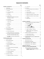
TABLE OF CONTENTS
page
page
B.
V.
Connection ...................................................... 13
I.
OVEN USES ............................................................. 4
GAS SUPPLY .......................................................... 14
II.
OVEN COMPONENTS ............................................. 4
A.
Gas Utility Rough-In Recommendations ....... 14
A.
Window ............................................................. 4
B.
Connection ....................................................... 14
B.
Conveyor End Stop ........................................... 4
C.
Gas Conversion .............................................. 14
C.
Eyebrows .......................................................... 4
D.
PS536 Propane Conversion ............................ 14
D.
End Plugs ......................................................... 4
E.
Adjusting the Maximum Pressure Setting ....... 14
E.
Control Panel .................................................... 4
F
Adjusting the Minimum Pressure Setting ....... 15
F.
Machinery Compartment and Control
Compartment Doors ........................................ 4
G.
Checkout .......................................................... 15
H.
Maintenance .................................................... 15
G.
Serial Plate ....................................................... 4
H.
Conveyor Drive Motor ....................................... 4
I.
Crumb Pans ..................................................... 4
J.
Conveyor ........................................................... 4
K.
Gas Burner ....................................................... 4
L.
Blowers ............................................................. 4
M.
Air Fingers ........................................................ 4
SECTION 3 - OPERATION ..................................................... 17
I.
III.
LOCATION AND DESCRIPTION OF CONTROLS . 17
A.
BLOWER (
B.
HEAT (
C.
CONVEYOR (
D.
Conveyor Speed Controller ............................. 17
E.
Digital Temperature Controller ....................... 17
F.
Machinery and Control Compartment
Safety Switches ............................................... 17
) Switch ..................................... 17
) Switch ............................................ 17
) Switch ............................... 17
OVEN SPECIFICATIONS ......................................... 4
A.
Dimensions ...................................................... 4
B.
General Specifications ..................................... 4
C.
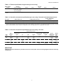
Electrical Specifications for Gas Ovens .......... 5
D.
Gas Orifice and Pressure Specifications Domestic and Standard Export Ovens ............ 5
E.
Gas Orifice and Pressure Specifications CE Ovens .......................................................... 5
II.
III.
NORMAL OPERATION, STEP-BY-STEP ................ 18
A.
Daily Startup Procedure .................................. 18
B.
Daily Shutdown Procedure ............................. 18
QUICK REFERENCE: DIGITAL TEMPERATURE
CONTROLLER ....................................................... 19
SECTION 2 - INSTALLATION .................................................. 6
SECTION 4 - MAINTENANCE ................................................. 20
I.
INSTALLATION KIT .................................................. 7
II.
VENTILATION SYSTEM ........................................... 8
A.
Requirements .................................................. 8
B.
Recommendations .......................................... 8
C.
Other Ventilation Concerns .............................. 8
I.
MAINTENANCE - DAILY .......................................... 20
II.
MAINTENANCE - MONTHLY .................................. 21
III.
MAINTENANCE - EVERY 3 MONTHS .................... 21
IV. MAINTENANCE - EVERY 6 MONTHS .................... 23
SECTION 5 - PARTS LIST ..................................................... 24
III.
ASSEMBLY ............................................................... 9
SECTION 5 - ELECTRICAL WIRING DIAGRAMS ................... 25
A.
Top Panel and Base Pad Assembly ............... 9
B.
Stacking ........................................................... 10
C.
Restraint Cable Installation ............................ 10
D.
Conveyor Installation ....................................... 11
E.
Final Assembly ................................................ 12
I.
IV. ELECTRICAL SUPPLY ........................................... 13
A.
Additional Information - Gas Ovens ................ 13
3
WIRING DIAGRAM, PS536GS GAS OVEN
(DOMESTIC & STD. EXPORT VERSION),
208/240V, 50/60 Hz, 1 Ph ................................ 25
ENGLISH
SECTION 1 - DESCRIPTION ................................................... 4
SECTION 1 - DESCRIPTION
I.
OVEN USES
J.
PS536GS ovens can be used to bake and/or cook a wide
variety of food products, such as pizza, pizza-type products,
cookies, sandwiches and others.
Not Shown:
ENGLISH
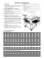
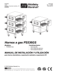
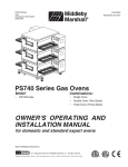
II. OVEN COMPONENTS - see Figure 1-1.
A.
Window: Allows the user to see and access food products
inside the baking chamber.
B.
Conveyor End Stop : Prevents food products from falling
off the end of the moving conveyor.
C.
Eyebrows: Can be adjusted to various heights to prevent
heat loss into the environment.
D.
End Plugs: Allow access to the oven's interior.
E.
Control Panel: Location of the operating controls for the
oven. Refer to Section 3, Operation, for details.
F.
Machinery Compartment and Control Compartment
Doors: Allow access to the oven's interior components.
One door is located at each end of the oven. No userservicable parts are located inside the machinery compartment or control compartment.
G.
Serial Plate: Provides specifications for the oven that affect
installation and operation. Refer to Section 2, Installation,
for details.
H.
Conveyor Drive Motor: Moves the conveyor.
I.
Crumb Pans: Catch crumbs and other material that drop
through the conveyor belt. One crumb pan is located
underneath each end of the conveyor.
Conveyor: Moves the food product through the oven.
K.
Gas Burner: Heats air, which is then projected to the air
fingers by the blowers.
L.
Blowers: Fans that project hot air from the gas burner to
the air fingers.
M. Air Fingers:
product.
Project streams of hot air onto the food
Fig. 1-1 - Oven Components
B
C
D
F
E
G
A
H
I
J
III. OVEN SPECIFICATIONS
Table 1-1: Dimensions
Overall Height:
single oven with 17-1/2" (446mm) legs
43-1/2" (1105mm)
double oven with standard 17-1/2" (446mm) legs
63" (1600mm)
double oven with optional 20-1/2" (521mm) legs
66" (1676mm)
double oven with optional 25-1/2" (648mm) legs
71" (1803mm)
triple oven with 6" (152mm) legs
71" (1803mm)
with standard 60"/1524mm conveyor
61" (1549mm)
with optional 56"/1422mm conveyor
57" (1447mm)
with optional 76"/1930mm conveyor
77" (1956mm)
Overall Depth:
Overall Length:
46" (1168mm)
Baking Chamber Length
36" (914mm)
Conveyor Width: Single Belt
20" (508mm)
Split Belt
2 x 9-1/2" (241mm)
Conveyor Length
56" (1422mm) or 60" (1524mm) or 76" (1930mm)
Recommended Minimum Clearances:
Rear of oven to wall
3" (76mm)
Control end of conveyor to wall
1" (25.4mm)
Non-control end of oven to wall
1" (25.4mm)
Table 1-2: General specifications (per oven cavity)
Weight
400 lbs. (182kg)
Rated Heat Input: Natural gas ovens
70,000 BTU (17,638 kcal, 20.51 kW/hr.)
Propane ovens
70,000 BTU (17,638 kcal, 20.51 kW/hr.)
Maximum Operating Temperature
550°F (288°C)
Warmup Time
25 minutes
4
SECTION 1 - DESCRIPTION
Main Blower
Voltage
Control
Circuit Voltage
208/240V
120V conv. speed control
& drive motor; all others
as per line (208/240V)
Phase
Freq.
Current
Draw
Poles
Wires
1 Ph
50/60 Hz
6A *
2 Pole
3 Wire (2 hot, 1 gnd)
* The current draw shown above is an average value for normal operation. The initial amperage draw on oven startup may exceed the listed
value.
Table 1-4: Gas orifice and pressure specifications (per oven cavity) - Domestic and standard export ovens
Main Orifice I.D.
Supply (Inlet) Pressure
Orifice (Manifold)
Pressure
Natural
0.0935” (2.3749mm, #42 drill)
6-12” W.C. (14.9-29.9mbar) *
4.0” W.C. (9.93mbar)
Propane
0.081” (2.0574mm, #46 drill)
11-14” W.C. (27.4-34.9mbar) *
10.5” W.C. (26.15mbar)
Gas Type
* The gas supply pressures and orifice sizes shown are for ovens installed in North America. The required gas supply pressures and orifice
sizes of ovens installed in other locations are dependent on the local gas type and on all applicable local codes.
Table 1-5: Gas orifice and pressure specifications (per oven cavity) - CE ovens
Supply (Inlet) Pressure
Main
Orifice
dia.
IT,PT,ES,SE,
UK,CH,IT,AT,
DK,FI
I 2H
G20
2.3749
mm
G25
G30
Gas
Type
SE,CH,AT,DK,
FI,DE,NL
I 3B/P
BE,IE,IT,PT,
ES,UK
I 3+
Orifice
(Manifold)
Pressure
Rated
Heat
Input
20
mbar
--
--
11.21
mbar
22.36
kW-hr.
--
--
--
--
16.19
mbar
22.36
kW-hr.
--
--
29 or 50
mbar
28-30, 37
or 50 mbar
26.2
mbar
22.59
kW-hr.
NL
I 2L
DE
I 2E
BE,FR
I 2E+
20
mbar
--
20
mbar
2.3749
mm
--
25
mbar
1.3970
mm
--
--
IMPORTANT
Additional electrical information is provided on the oven's serial plate, and on the wiring diagram inside the machinery
compartment.
5
ENGLISH
Table 1-3: Electrical specifications for gas ovens (per oven cavity)
SECTION 2 - INSTALLATION
WARNING - For gas ovens, after any conversions, readjustments, or service work on the oven:
ENGLISH
•
•
•
•
Perform a gas leak test.
Test for correct air supply.
Test for proper combustion and gas supply.
Check that the ventilation system is in operation.
WARNING
Keep the appliance area free and clear of combustibles.
WARNING
The oven must be installed on an even (level) non-flammable flooring and any adjacent walls must
be non-flammable. Recommended minimum clearances are specified in the Description section of
this Manual.
WARNING
Do not obstruct the flow of combustion and ventilation air to and from your oven. There must be no
obstructions around or underneath the oven. Constructional changes to the area where the oven is
installed shall not affect the air supply to the oven.
CAUTION
For additional installation information, contact your local Authorized Service Agent.
NOTE
There must be adequate clearance between the oven and combustible construction. Clearance
must also be provided for servicing and for proper operation.
NOTE
An electrical wiring diagram for the oven is located inside the machinery compartment.
NOTE
All aspects of the oven installation, including placement, utility connections, and ventilation requirements,
must conform with any applicable local, national, or international codes. These codes supersede the
requirements and guidelines provided in this manual.
NOTE
In the USA, the oven installation must conform with local codes. In the absence of local codes, gas oven
installations must conform with the National Fuel Gas Code, ANSI Z223.1. Installed ovens must be
electrically grounded in accordance with local codes, or in the absence of local codes, with the National
Electrical Code (NEC), or ANSI/NFPA70.
NOTE
In Canada, the oven installation must conform with local codes. In the absence of local codes, gas oven
installations must conform with the Natural Gas Installation Code, CAN/CGA-B149.1, or the Propane Gas
Installation Code, CAN/CGA-B149.2, as applicable. Installed ovens must be electrically grounded in
accordance with local codes, or in the absence of local codes, with the Canadian Electrical Code CSA C22.2.
NOTE
In Australia, the oven installation must conform with any requirements of the appropriate statutory authority.
Gas oven installtions must conform with AGA Codes AG311 and AG601.
NOTE
In CE countries, all aspects of the gas supply connection must comply with current IEC/CEE requirements and
with all applicable local, national, and international codes. In addition, four casters are provided to allow the oven
to be more easily moved to the installation location. These casters are intended to simplify pre-installation
movement only, and are NOT suitable for use as part of a CE oven installation. During the installation procedure,
the casters MUST be removed, so that the oven can be supported by the supplied 152mm adjustable legs.
6
SECTION 2 - INSTALLATION
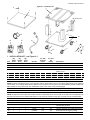
Figure 2-1 - Installation Kit
2
3
4a, 4b, 4c, 4d
8
12
16
14
13
15
6
11
5
10
7
9
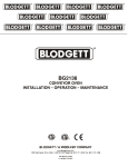
I.
INSTALLATION KIT - see Figure 2-1
Item
1
Qty.
Single
Oven
1
Qty.
Double
Oven
1
Qty.
Triple
Oven
1
Part No.
48605
Inc. with
domestic
ovens?
Yes
Inc. with
CE
ovens?
Yes
2
4
4
4
3A80A8801
Yes
Yes
Screw, pan head #10 x 2″
3
4a
1
4
1
4
1
--
42893
42890
Yes
Yes
Yes
Yes
Base pad
17-1/2″ (445mm) leg extension, for single and
double ovens
4b
4c
---
4
4
---
45360
45329
Yes
Yes
Yes
Yes
20-1/2″ (521mm) leg extension, optional
25-1/2″ (648mm) leg extension, optional
4d
--
--
4
44799
Yes
Yes
6″ (152mm) leg extension, for triple ovens
5
6
2
A/R
2
A/R
2
A/R
22290-0009
22290-0010
Yes
Yes
No
Yes
Caster, with flat plate and brake
Caster, with flat plate (no brake)
Description
Top panel
NOTE: Domestic and standard export ovens include 2 braking casters (item 5) and 2 non-braking casters (Item 6). CE-approved
ovens include 4 non-braking casters (Item 6) SOLELY for the purpose of moving the oven to the installation location. Casters are
NOT suitable for use as part of CE oven installations. Refer to the notice on the preceding page.
7
4
4
4
22450-0028
No
Yes
Leg, adjustable, 6″ (152mm)
8
9
1
A/R
1
A/R
1
A/R
21392-0004
220373
Yes
Yes
No
Yes
Eyebolt, 3/4″
Hex bolt, 3/8″-16 x 1″
NOTE: CE-approved ovens include 32 hex bolts. Domestic and standard export ovens include 31 hex bolts and one eyebolt (item 8)
that acts as an anchor for the restraint cable (Item 12). CE ovens are mounted on legs (Item 7) and do not use a restraint cable.
10
32
32
32
21416-0001
Yes
Yes
Flat washer, 3/8″
11
32
32
32
21422-0001
Yes
Yes
Lockwasher, 3/8″
12
13
1
1
1
2
1
3
22450-0228
22361-0001
Yes
Yes
No
No
Restraint cable assembly
Gas hose, 3/4″ to 1/2″ Gas hose reducer
included with gas hose.
14
15
1
1
1
1
1
1
50236
1002040
Yes
Yes
Yes
Yes
Owner's Operating and Installation Manual
Authorized Service Agency Listing
16
1
1
--
46393
Yes
Yes
Lower shelf
7
ENGLISH
1
SECTION 2 - INSTALLATION
B.
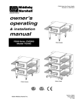
II. VENTILATION SYSTEM
NOTE THAT THE HOOD DIMENSIONS SHOWN IN FIGURE 22 ARE RECOMMENDATIONS ONLY. LOCAL, NATIONAL AND
INTERNATIONAL CODES MUST BE FOLLOWED WHEN
INSTALLING THE VENTILATION SYSTEM. ANY APPLICABLE
CODES SUPERSEDE THE RECOMMENDATIONS SHOWN IN
THIS MANUAL.
IMPORTANT
ENGLISH
Where national or local codes require the
installation of fire suppression equipment or other supplementary equipment,
DO NOT mount the equipment directly to
the oven.
MOUNTING SUCH EQUIPMENT ON
THE OVEN MAY:
• VOID AGENCY CERTIFICATIONS
• RESTRICT SERVICE ACCESS
• LEAD TO INCREASED SERVICE EXPENSES FOR THE OWNER
A.
Recommendations
The rate of air flow exhausted through the ventilation system
may vary depending on the oven configuration and hood design.
Consult the hood manufacturer or ventilation engineer for these
specifications.
To avoid a negative pressure condition in the kitchen area,
return air must be brought back to replenish the air that was
exhausted. A negative pressure in the kitchen can cause heatrelated problems to the oven components as if there were no
ventilation at all. The best method of supplying return air is
through the heating, ventilation and air conditioning (HVAC)
system. Through the HVAC system, the air can be temperaturecontrolled for summer and winter. Return air can also be
brought in directly from outside the building, but detrimental
effects can result from extreme seasonal hot and cold
temperatures from the outdoors.
Requirements
CAUTION
Gas oven installations REQUIRE a mechanically driven
ventilation system with electrical exhaust air sensing control.
NOTE: Return air from the mechanically driven system must not
blow at the opening of the baking chamber. Poor oven baking
performance will result.
A mechanically driven ventilation system is STRONGLY
RECOMMENDED for electric oven installations.
C.
Other ventilation concerns
•
Special locations, conditions, or problems may require the
services of a ventilation engineer or specialist.
•
Inadequate ventilation can inhibit oven performance.
•
It is recommended that the ventilation system and duct
work be checked at prevailing intervals as specified by the
hood manufacturer and/or HVAC engineer or specialist.
PROPER VENTILATION OF THE
RESPONSIBILITY OF THE OWNER.
OVEN
IS
THE
Fig. 2-2 - Ventilation System
12" (305mm)
minimum
12" (305mm)
minimum
8" (203mm)
minimum
1" (25mm)
minimum
2" (51mm)
minimum
8
SECTION 2 - INSTALLATION
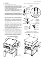
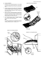
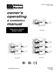
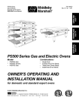
III. ASSEMBLY
Figure 2-3 - Leg extension and casters installation
Top Panel and Base Pad Assembly
1.
Install the four leg extensions onto the base pad using the
3/8"-16x1" screws, 3/8" flat washers, and 3/8" lockwashers
supplied in the Base Pad Kit. See Figure 2-3. Check that
the finished sides of each leg extension face OUTWARDS.
Finished sides of
leg extension
face corner of
base pad
3/8" flat
washer
For domestic and standard export ovens:
One rear leg should be attached using three 3/8"-16 x 1"
screws and the 3/4" eyebolt, as shown in Figure 2-3. This
eyebolt acts as the anchor point for the restraint cable
assembly (see Part C, Restraint Cable Installation).
2.
3.
3/8" lock
washer
CE ovens
do not use
the
eyebolt.
If your oven is equipped with the lower shelf, position it in
place as shown in Figure 2-3. Check that the lip on the shelf
faces DOWN. Seal joint between leg and shelf with NSF
listed silicone.
3/8"-16 x 1"
hex screw
3/4" eyebolt
(inside corner
of one rear leg
extension
only)
For domestic and standard export ovens:
Install one caster onto each leg extension, as shown in
Figure 2-4. Use the 3/8"-16x1" screws, 3/8" flat washers,
and 3/8" lockwashers supplied in the Installation Kit. The
locking casters should be installed at the FRONT of the
oven. The non-locking casters should be installed at the
REAR of the oven.
Lower
shelf
Locking casters FRONT of oven
Non-locking casters REAR of oven
For CE export ovens:
The Installation Kit includes four casters AND four 152mm
adjustable legs. The casters are provided to allow the oven
to be more easily moved to the installation location, and are
NOT suitable for use as part of the oven installation. Refer
to the notice at the beginning of this Section.
Install the lower oven cavity onto the base pad. See Fig. 2-4.
5.
For single ovens ONLY, install the top panel using the
screws included in the base pad kit, as shown in Figure 25. Then, skip ahead to Part C, Restraint Cable Installation.
3/8" flat
washer
CE-approved
ovens:
After the oven is at the installation location, install one
152mm adjustable leg into the center hole on the bottom
of each leg extension, as shown in Figure 2-4.
4.
Domestic and
standard export
ovens:
3/8" lock
washer
152mm adjustable
leg MUST be used
for installation
3/8"-16 x 1"
hex screw
Figure 2-5 - Top panel installation
NOTE: DO NOT install top panel onto double or triple ovens
until AFTER stacking the oven cavities. See Part B, Stacking.
For double or triple ovens, continue on to Part B, Stacking.
Note that the top panel should NOT be installed for double
and triple ovens until after stacking the oven cavities.
#10 x 2"
screws
Figure 2-4 - Base pad installation
Bottom oven
cavity
Assembled
base pad
9
Top
panel
ENGLISH
A.
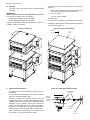
SECTION 2 - INSTALLATION
B.
Stacking
1.
For single ovens, skip ahead to Part C, Restraint Cable
Installation.
Stack an oven cavity on top of the lower oven. Check the
following:
ENGLISH
•
All four sides of the lower lip (on the bottom edge of the
oven cavity) overlap the top of the lower oven.
IMPORTANT
Middleby Marshall STRONGLY RECOMMENDS that PS536GS
oven cavities be stacked using the following:
•
The oven is level.
•
The oven is firmly seated.
•
•
See Figure 2-6.
PS500 Series Stacking Lift Kit, P/N 30580
PS536 Stacking Hardware Kit, P/N 46494
Contact your Middleby Marshall Authorized Service Agent for
complete stacking instructions.
2.
For triple ovens, repeat Step 1 to install the top oven cavity.
3.
Install the top panel using the screws included in the base pad
kit, as shown in Figure 2-7.
Figure 2-7 - Top panel installation
Figure 2-6 - Stacking
#10 x 2"
screws
C.
Restraint Cable Installation
Top
panel
Figure 2-8 - Installing the Restraint Cable
For CE-approved ovens, skip ahead to Part D, Conveyor
Installation.
Restraint cable
assembly
For domestic and standard export ovens, continue with this
Section to install the restraint cable.
3/8"-16 x 1"
eyebolt on
rear leg
extension
Because domestic and standard export ovens are
equipped with casters, a restraint cable assembly must be
installed to limit the movement of the appliance without
depending on the connector and the quick disconnect
device or its associated piping. One end of the cable is
anchored to the eyebolt on one of the rear leg extensions,
while the other is anchored to the wall. See Figure 2-8.
3/4” (19mm)
eyebolt
After connecting the restraint cable, move the oven to its
final location. Then, lock the two front casters.
Wall of
structure
10
SECTION 2 - INSTALLATION
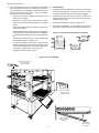
Conveyor Installation
1.
Unfold the conveyor as shown in Figure 2-9. Then, begin
to slide the conveyor into the end of the oven. The conveyor
can only be installed from the end of the oven with the drive
motor.
2.
Continue moving the conveyor into the oven until the frame
protrudes equally from each end of the oven. Check that the
crumb tray supports located on the underside of the conveyor frame rest firmly against the lower end plugs, as
shown in Figure 2-10.
3.
When the conveyor is positioned properly, check for freedom of movement of the conveyor belt by pulling it for about
2-3 feet (0.6-1.0m) with your fingers. The drive and idler
shafts must rotate smoothly, and the belt must move freely
without rubbing on the inside of the oven.
4.
Check the tension of the conveyor belt as shown in Figure
2-11. The belt should lift about 1" (25mm). DO NOT
OVERTIGHTEN THE CONVEYOR BELT.
Figure 2-9 - Conveyor installation
Folded
frame
Idler end (with
belt tension
adjustment
screws)
NOTE:
If necessary, the belt tension can be adjusted by turning the
conveyor adjustment screws, located at the idler (noncontrol) end of the conveyor. See Figure 2-11.
Drive end (with
drive sprocket)
Figure 2-10 - Conveyor placement
Figure 2-11 - Conveyor belt tension
Crumb tray
support
bracket
End plug
Conveyor
placed in
oven
1" (25mm)
vertical
deflection
Adjustment
screws (2) on
idler end of
conveyor
11
ENGLISH
D.
SECTION 2 - INSTALLATION
5.
ENGLISH
If it is necessary to add or remove conveyor links to achieve
the correct tension, OR if it is necessary to reverse the
conveyor belt for correct orientation, the belt will need to be
removed from the conveyor frame. If this is necessary,
perform the following procedure:
E.
Final Assembly
6.
Install the drive chain between the conveyor drive sprocket
and the motor sprocket. To install the chain, it will be
necessary to lift the drive end of the conveyor slightly.
•
Remove the conveyor assembly from the oven and
place it flat on the floor.
7.
•
Remove the master links using long-nose pliers.
Then, roll up the belt along the length of the conveyor
frame.
Install the conveyor chain cover as shown in Figure 2-13.
Check that the chain cover does not bind on the conveyor
sprocket or drive shaft.
8.
Install the crumb trays as shown in Figure 2-13.
9.
Press the end stop down over the edge of the conveyor
frame at the exit end of the oven, as shown in Figure 2-13.
•
Add or remove belt links as necessary to achieve the
correct belt tension.
•
Replace the belt on the conveyor frame. Check that the
conveyor belt links are oriented as shown in Figure 212, and that the smooth side of the conveyor belt faces
UP.
Connect the inside master links. Check that the links
are oriented as shown in Figure 2-12.
•
•
•
Figure 2-12 - Conveyor and master link orientation
Direction
of travel
Connect the outside master links. Note that the
outside master links each have an open hook on one
side. This hook aligns with the hooks along the sides
of the other conveyor links. See Figure 2-12.
CORRECT
master link
position
Incorrect
master link
position
Replace the conveyor into the oven.
Figure 2-13 - Final assembly
Press conveyor end stop
down over edge of
conveyor frame
Hang chain cover on
screws in control
compartment wall
Place inside edge
of tray on retainer
bracket
Swing outside
edge of tray up
and into place
12
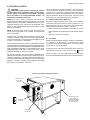
SECTION 2 - INSTALLATION
WARNING
Authorized supplier personnel normally accomplish
the connections for the ventilation system, electric supply,
and gas supply, as arranged by the customer. Following
these connections, the factory-authorized installer can
perform the initial startup of the oven.
The oven requires a ground connection to the oven ground
screw located in the electrical junction box. (The box is shown
in Figure 2-14.) The ground connection must comply with all
applicable local, national, and international codes. If necessary,
have the electrician supply the ground wire. Do NOT use the
wiring conduit or other piping for ground connections!
NOTE: The electric supply installation must satisfy the
requirements of the appropriate statutory authority, such as the
National Electrical Code (NEC), ANSI/NFPA70, (U.S.A.); the
Canadian Electrical Code, CSA C22.2; the Australian Code,
AG601; current IEC/CEE requirements (CE countries); or other
applicable regulations.
A.
Additional Information - Gas Ovens
All electric supply connections are made via the electrical
junction box on the rear of the oven, shown in Figure 2-14. The
power lines then connect to the oven circuits through safety
switches that interrupt electric power to the oven:
NOTE: All aspects of the electrical supply connection must
comply with all applicable local, national, and international
code requirements.
Check the oven serial plate before making any electric supply
connections. Electric supply connections must agree with data
on the oven serial plate. The location of the serial plate is shown
in Figure 1-1 (in Section 1, Description).
•
When the Control Compartment Access Panel is opened;
•
When the Machinery Compartment Access Panel is opened,
OR
•
When the rear panel is removed.
B.
Connection
Refer to the wiring diagram inside the machinery compartment,
or in Section 5 of this Manual, to determine the correct
connections for the electrical supply lines. Connect the supply
as indicated on the wiring diagram.
A fused disconnect switch or a main circuit breaker (customer
furnished) MUST be installed in the electric supply line for each
oven cavity. It is recommended that this circuit breaker/disconnect
have lockout/tagout capability. For CE installations, the circuit
breaker/disconnect must have a minimum of 3mm contact
separation breaking all poles of the supply.
If required by local, national or international codes, connect an
equipotential ground wire to the lug next to the
symbol
(shown in Figure 2-14). The equipotential ground connection
The supply conductors must comply with all applicable local,
national and international codes. Supply conductors must be
insulated copper wiring, #18 AWG (American Wire Gauge) or
equivalent. Additional wiring information is shown on the wiring
diagrams in Section 5, Electrical Wiring Diagrams and inside
the machinery compartment of the oven.
must meet all applicable national and local code requirements.
Figure 2-14 - Utility connection locations
33mm cutout for
electric utility
connection
1/2" NPT pipe for gas
utility connection
(fitted with 3/4" adapter
for use with supplied
3/4" dia. gas hose)
Equipotential
ground lug
Electrical
Junction Box
13
ENGLISH
IV. ELECTRICAL SUPPLY
SECTION 2 - INSTALLATION
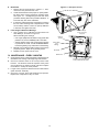
V. GAS SUPPLY
Appliances, ANSI Z21.69 (in U.S.A.), as well as a quick-disconnect
device that complies with the Standard for Quick-Disconnect
Devices for Use With Gas Fuel, ANSI Z21.41 (in U.S.A.).
CAUTION
DURING PRESSURE TESTING NOTE THE FOLLOWING:
C.
ENGLISH
1. The oven and its individual shutoff valve must be disconnected from the gas supply piping system during any
pressure testing of that system at test pressure in excess
of 1/2 psi (3.45 kPa).
Where permitted by local and national codes, it is possible to
convert ovens from natural to propane gas, or from propane to
natural gas. Use the appropriate Middleby Gas Conversion Kit
for the specific oven model.
2. The oven must be isolated from the gas supply piping
system by closing its individual manual shutoff valve
during any pressure testing of the gas supply piping
system at test pressure equal to or less than 1/2 psi
(3.45 kPa).
CAUTION:
D.
3. If incoming pressure is over 14" W.C. (35mbar), a
separate regulator MUST be installed in the line BEFORE
the individual shutoff valve for the oven.
The terms of the oven’s warranty require all startups, conversions and service work to be performed by a Middleby Authorized Service Agent.
PS536 Propane Conversion
Two items have to be changed, to change the oven to LP:
WARNING: To prevent damage to the control valve regulator during initial turn- on of gas, it is very important to
open the manual shutoff valve very slowly.
1.
Replace main orifices.
2.
Adjust main gas regulator per instructions below.
Disconnect the manifold union closest to the main burner, and
remove the manifold assembly (four screws). Slide out the
manifold assembly (leaving the ignition and sense wires connected). Replace the main orifices.
After the initial gas turn-on, the manual shutoff valve must
remain open except during pressure testing as outlined
in the above steps or when necessary during service
maintenance.
A.
Gas Conversion
Replace the main orifices on the manifold assemblies with the LP
units, and replace the manifold assembly. Reconnect the union.
Gas Utility Rough-In Recommendations
The following gas system specifications are STRONGLY
RECOMMENDED. Deviating from these recommendations
may affect the baking performance of the oven.
E.
Adjusting the Maximum Pressure Setting
1.
Disconnect pressure feedback connection (if appcable).
2.
Connect a suitable pressure gauge to pipe line or to
outlet pressure tap of gas control concerned, to measure burner pressure (measuring point must be as near
to burner as possible).
3.
Make sure that the appliance is in operation and the
Moduplus® coil is energized with maximum current.
If maximum rate pressure needs adjustment, use an 8 mm
wrench to turn adjustment screw for maximum pressure
setting (clockwise to increase or counter-clockwise to decrease pressure), until the desired maximum outlet pressure is obtained.
Gas Meter - 650 cfh (307l/min) meter
Gas Line
•
DEDICATED LINE from the gas meter to the oven
•
2" (50.8mm) pipe for natural gas
•
1-1/2" (38.1mm) pipe for propane
•
Maximum length: 200' (61m). Each 90° elbow equals 7'
(2.13m) of pipe.
4.
B. Connection
Check the oven’s gas supply requirements before making the
gas utility connection. Gas supply requirement are listed on the
oven’s serial plate and in Table 1-4. Gas Orifice and Pressure
Specifications (in Section 1, Description).
Check the serial plate to determine the type of gas (Propane or
Natural) to be used with the oven.
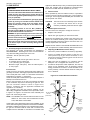
Refer to the instructions in the gas hose package (included
in the Installation Kit) before connecting the gas line. One
gas line connection method is shown in Figure 2-18;
however, compliance with the applicable standards and
regulations is mandatory.
Inlet, regulated, and pilot gas pressure readings can be
taken using a digital tube manometer at the tap location shown
in Figure 2-19. Figure 2-19 shows the burner assembly and
Figure 2-21 shows the gas valve.
Figure 2-15 - Flexible Gas Hose Installation
1/2" gas
pipe nipple
3/4"-1/2"
gas pipe
reducer
To Gas
Supply
Pipe
3/4" gas
pipe nipple
1/2" gas line
tee with
pressure tap
NOTE: The installation must conform with local codes or in the
absence of local codes, with the National Fuel Gas
Code, ANSI Z223.1-latest edition.
90°
Elbow
Full-Flow
Gas
Shutoff
Valve
Certain safety code requirements exist for the installation of gas
ovens; refer to the beginning of Section 2 for a list of the installation
standards. In addition, because the oven is equipped with casters,
the gas line connection shall be made with a connector that
complies with the Standard for Connectors for Movable Gas
Quickdisconnect
device
14
Flexible
Gas Hose
Individual gas
connection for
each oven
cavity
5.
6.
Gas Burner
7.
8.
Disconnect electrical connection of the Moduplus®.
Check minimum pressure setting and readjust if
necessary. (See Adjusting Minimum Pressure Setting for
proper adjusting procedure.)
Reconnect pressure feedback connection (if appcable).
If minimum and maximum pressures are set, wire the
Moduplus® in circuit.
9. Close pressure tap screw.
F.
Adjusting the Minimum Pressure Setting
1.
Disconnect pressure feedback connection (if appcable).
2.
Connect a suitable pressure gauge to pipe line or to outlet
pressure tap of gas control concerned, to measure burner
pressure (measuring point must be as near to burner as
possible).
3.
Disconnect electrical connection of the Moduplus®.
4.
Energize operator, set control in operation and wait until an
outlet pressure is recorded on pressure gauge.
5.
If minimum rate pressure needs adjustment, use an 8 mm
wrench to turn adjustment screw for minimum pressure
setting (clockwise to increase or counter-clockwise to
decrease pressure), until the desired minimum outlet
pressure is obtained.
6.
Check if main burner lights easily and reliable at minimum
pressure.
7.
Reconnect pressure feedback connection (if appcable).
8.
Close pressure tap screw.
G.
Checkout
Manifold Pressure Tap
Figure 2-17. Burner Assembly
Gas
Valve
After any adjustment, set appliance in operation and observe
through a component cycle to ensure that burner system components function correctly.
H.
Main•
Pressure•
Tap
It is recommended to check yearly the minimum and the
maximum setting and readjust them if necessary.
Main•
Orifices
Gas Burner
Assembly
Figure 2-18. Gas Valve
Adjustment Screw (5 mm)
for minimum pressure
setting
Maintenance
Adjustment Screw
(8 mm) for
maximum
pressure
setting
15
ENGLISH
SECTION 2 - INSTALLATION
Figure 2-16. Gas Burner Assembly
SECTION 2 - INSTALLATION
NOTES
ENGLISH
16
ENGLISH
SECTION 3 - OPERATION
E
D
B
A
C
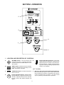
I.
LOCATION AND DESCRIPTION OF CONTROLS
A.
"BLOWER" Switch: Turns the blowers and
cooling fans on and off. The HEAT Switch has
no effect unless the BLOWER Switch is in the
“ON” position.
B.
"HEAT" Switch: Allows the burner to activate.
Activation is determined by the settings on the
Digital Temperature Controller.
C.
"CONVEYOR" Switch: Turns the conveyor drive
motor on and off.
D.
Conveyor Speed Controller: Adjusts and displays the bake time. Single-belt ovens have one
controller. Split belt ovens have one controller
for each conveyor belt, labeled "FRONT" and
"BACK."
E.
Digital Temperature Controller: Continuously
monitors the oven temperature. Settings on the
Digital Temperture Controller control the activation of the burner. Keypad controls allow the
operator to select the cooking temperature and
monitor oven operation.
NOT SHOWN:
F.
17
Machinery and Control Compartment Safety Switches:
Disconnect electrical power to the controls and blowers
when EITHER the machinery compartment door OR the
control compartment door is opened. The doors should
only be opened by authorized service personnel.
SECTION 3 - OPERATION
II. NORMAL OPERATION - STEP-BY-STEP
A.
DAILY STARTUP PROCEDURE
1.
Check that the circuit breaker/fused disconnect is in the on
position. Check that the window is closed.
ENGLISH
2.
3.
4.
5.
7.
Wait for the oven to heat to the setpoint temperature. Higher
setpoint temperatures will require a longer wait. The oven
can reach a temperature of 500°F (232°C) in approximately
5 minutes.
8.
(Optional) Press the Temperature ( ) key to show
the Actual Temperature
in the display, and wait
for the "ACTUAL TEMP"
light to turn on. This allows you to monitor the
oven temperature as it
rises to the setpoint.
Turn the "BLOWER" ( )
switch to the “ON” ("I")
position.
Turn the "CONVEYOR"
) switch to the “ON”
(
("I") position.
If necessary, adjust the
conveyor speed setting
or
by pressing the
pushbuttons on the conveyor speed controller to
change the displayed
bake time.
Adjust the temperature
controller to a desired set
temperature, if necessary.
•
•
Allow the oven to preheat for 10 minutes after it has reached
the set point temperature.
B.
DAILY SHUTDOWN PROCEDURE
1.
Turn the "HEAT" ( ) and
"BLOWER" ( ) switches to the "OFF" ("O")
position. Note that the
blowers will remain in operation until the oven has
cooled to below 200°F
(93°C).
or
+
2.
Make certain that there
are no products left on
the conveyor inside the
oven. Turn the "CONVEYOR" (
) switch to
the "OFF" ("O") position.
3.
Open the window to allow the oven to cool faster.
4.
After the oven has cooled and the blowers have turned off,
switch the circuit breaker/fused disconnect to the off position.
wait
for
Press the Set Point
and Unlock keys at
the same time. Wait
for the "SET PT" light
to turn on.
Press the Up Arrow
and Down Arrow
Keys as necessary
to adjust the setpoint.
9.
or
+
wait
for
IMPORTANT
6.
On gas ovens, if the "HEAT ON" light will not illuminate, OR
if the oven does not heat, the gas burner may not have lit.
Turn the "HEAT" ( ), "BLOWER" ( ), and "CONVEYOR"
(
) switches to the "OFF" ("O") position. Wait for AT
LEAST FIVE MINUTES before restarting the oven. Then,
repeat the Daily Startup procedure.
Turn the "HEAT" ( )
switch to the "ON" ("I")
position, and wait for the
"HEAT ON" light to turn
on.
CAUTION
In case of power failure, turn all switches to the “OFF” ("O")
position, open the oven window, and remove the product.
After the power has been restored, perform the normal
startup procedure. IF THE OVEN WAS SWITCHED OFF
FOR LESS THAN 5 MINUTES, WAIT FOR AT LEAST FIVE
MINUTES BEFORE RESTARTING THE OVEN.
wait
for
The burner will not operate and gas will not flow through
the burner without electric power. No attempt should be
made to operate the oven during a power failure.
18
SECTION 3 - OPERATION
Display
ENGLISH
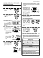
III. QUICK REFERENCE: DIGITAL TEMPERATURE CONTROLLER
"HEAT ON"
Light
Shows the Set Point
or the Actual Temperature in degrees
Fahrenheit (F) or
Celsius (C).
Lights when the
burner is in
operation.
"SP LOCK"
Light
Lights when the
set point is locked
out from changes.
This setting can
only be changed by
service personnel.
"SET PT"
(setpoint)
Light
Lights when the
set point is shown
in the display.
OVERTEMP
Light
Lights when the oven
temperature is
greater than 650°F
(343°C). Refer to
Quick Reference:
Troubleshooting in
this section.
"ACTUAL
TEMP" Light
Temperature
Key
Service Key
Lights when the
Actual Temperature is shown in
the display.
Service use
only.
Press this key once
to view the Actual
Temperature in the
Display.
Set Point Key
Unlock Key
Press this key
together with the Set
Point Key to allow the
Set Point to be
changed. Changes
can only be made for
60 seconds.
Up Arrow and Down
Arrow Keys
Press these keys to
adjust the Set Point up or
down. If the Set Point will
not change, refer to Set
Point Key and Unlock Key
in this section.
19
Press this key
together with the
Unlock Key to allow
the Set Point to be
changed.
Changes can only be
made for 60 seconds.
SECTION 4 - MAINTENANCE
WARNING
Before ANY cleaning or servicing of the oven, perform the following procedure:
ENGLISH
1.
2.
3.
4.
Switch off the oven and allow it to cool. Do NOT service the oven while it is warm.
Turn the full-flow gas safety valve to the off position.
Turn off the electric supply circuit breaker(s) and disconnect the electric supply to the oven.
If it is necessary to move a gas oven for cleaning or servicing, disconnect the gas supply before moving the oven.
When all cleaning and servicing is complete:
1. If the oven was moved for servicing, return the oven to its
original location.
2. Reconnect the gas supply.
3. Reconnect the electrical supply.
4.
5.
6.
Turn on the full-flow gas safety valve. Test the gas line
connections for leaks using approved leak test substances or thick soap suds.
Turn on the electric supply circuit breaker(s).
Perform the normal startup procedure.
WARNING
Possibility of injury from moving parts and electrical shock exists in this oven. Switch off and lockout/tagout the electric
supply BEFORE beginning to disassemble, clean, or service any oven. Never disassemble or clean an oven with the
BLOWER ( ) switch or any other circuit of the oven switched on.
CAUTION
NEVER use a water hose or pressurized steam-cleaning equipment when cleaning this oven. To avoid saturating the oven
insulation, DO NOT use excessive amounts of water. DO NOT use a caustic oven cleaner, which can damage the bake
chamber surfaces.
NOTE
ANY replacement parts that require access to the interior of the oven may ONLY be replaced by a Middleby Marshall Authorized
Service Agent. It is also strongly recommended that the 3-Month Maintenance and 6-Month Maintenance procedures in this
section be performed ONLY by a Middleby Marshall Authorized Service Agent.
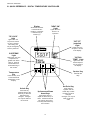
Figure 4-1 -Cooling Vents and Grills
I. MAINTENANCE - DAILY
A.
Check that the oven is cool and the power is disconnected,
as described in the warning at the beginning of this Section.
B.
Clean ALL of the cooling fan grills and vent openings with a
stiff nylon brush. Refer to Figure 4-1 for the locations of the
grills and vents.
C.
Clean the outside of the oven with a soft cloth and mild
detergent.
D.
Check that ALL cooling fans are operating properly.
CAUTION
If a cooling fan is not operating correctly, it must be replaced
IMMEDIATELY. Operating the oven without adequate
cooling can seriously damage the oven's internal components.
E.
Clean the conveyor belts with a stiff nylon brush. This is
more easily accomplished by allowing the conveyor to run
while you stand at the exit end of the conveyor. Then, brush
the crumbs off the conveyor as it moves.
F.
Remove and clean the crumb trays. If necessary, refer to
Figure 2-13 (in Section 2, Installation) when replacing the
crumb trays into the oven.
G.
Clean the window in place.
Vents on
front panel
of oven
Vents on rear
of control
compartment
door
20
Fan grills (2) on rear
of oven and control
compartment
Vent (1) on rear
of machinery
compartment
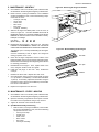
SECTION 4 - MAINTENANCE
Figure 4-2 - Removing Air Fingers and Plates
A.
Check that the oven is cool and the power is disconnected,
as described in the warning at the beginning of this Section.
B.
Refer to Part D, Conveyor Installation, in the Installation
section of this Manual. Then, remove the following components from the oven:
•
Conveyor end stop
•
Crumb trays
•
Chain cover
•
Drive chain
•
End plugs
•
Conveyor assembly
C.
Slide the air fingers and blank plates out of the oven, as
shown in Figure 4-2. AS EACH FINGER OR PLATE IS
REMOVED, WRITE A "LOCATION CODE" ON IT WITH A
MARKER to make sure that it can be reinstalled correctly.
Example of markings:
(Top Row)
T1 T2 T3 T4
(Bottom Row)
B1 B2 B3 B4
D.
Disassemble the air fingers. See Figure 4-3. AS EACH
FINGER IS DISASSEMBLED, WRITE THE "LOCATION
CODE" FOR THE FINGER ON ALL THREE OF ITS PIECES.
This will help you in correctly reassembling the air fingers.
CAUTION
Incorrect reassembly of the air fingers will change the
baking properties of the oven.
E.
Clean the air finger components and the interior of the
baking chamber using a vacuum cleaner and a damp cloth.
Refer to the boxed warnings at the beginning of this Section
for cleaning precautions.
F.
Reassemble the air fingers. Then, replace them in the
oven, using the "location code" as a guide.
G.
Install the end plugs on the oven. Then, reinstall the
conveyor.
I.
Reattach the drive chain. Replace the chain cover.
J.
Check the tension of the conveyor belt as shown in Figure
2-11 (in Section 2, Installation). The belt should lift about
1" (25mm). If necessary, adjust the belt tension using the
procedure in Part D (Conveyor Installation) in the Installation section of this Manual.
K.
Replace all components onto the oven.
ENGLISH
II. MAINTENANCE - MONTHLY
Figure 4-3 - Disassembling the Air Fingers
Outer Plate
Inner plate
Manifold
III. MAINTENANCE - EVERY 3 MONTHS
A.
Check that the oven is cool and the power is disconnected,
as described in the warning at the beginning of this Section.
B.
Open the machinery compartment access panel. Vacuum
the inside of the compartment using a shop vacuum.
C.
Tighten all electrical control terminal screws.
D.
Split Belt Disassembly and Cleaning
1.
Refer to Part D, Conveyor Installation, in the Installation section of this Manual. Then, remove the following
components from the oven:
•
Conveyor end stop
•
Crumb trays
•
Chain cover
•
Drive chains
•
End plugs
•
Conveyor assembly
21
SECTION 4 - MAINTENANCE
ENGLISH
2.
Remove the master links from each conveyor belt.
Then, roll the belts up along the length of the conveyor
to remove them from the frame.
3.
Remove the two conveyor adjustment screws from the
idler end of the conveyor frame, as shown in Figure 44.
4.
Remove the idler shaft assembly from the conveyor.
5.
Pull apart the two sections of the idler shaft.
6.
Clean the shafts thoroughly using a rag. Then, lubricate both the extended shaft and the interior of the
hollow shaft using a light food-grade lubricant. DO
NOT lubricate the shafts using WD40 or a similar
product. This can cause the shafts to wear rapidly.
7.
Before reassembling the shafts into the conveyor
frame, check that they are oriented properly.
8.
Reassemble the idler shaft into the conveyor. Make
sure that the bronze washer is in place between the
two sections of the shaft. See Figure 4-4.
9.
Replace the conveyor adjustment screws as shown in
Figure 4-4. To allow the conveyor belt to be reinstalled
later, do not tighten the screws at this time.
Figure 4-4 - Disassembling the idler shaft
Disassemble,
clean, and
lubricate shafts
Bronze
washer
Remove
adjustment
screws
Figure 4-5 - Drive shaft configurations
10. Loosen the set screw on both of the conveyor drive
sprockets. Then, remove the sprockets from the shaft.
Flange bearing
(used with highspeed conveyors)
11. Check the conveyor configuration as follows:
•
High-speed conveyors are equipped with large
flange bearings at both ends of the shaft, as
shown in Figure 4-5. For these conveyors, remove the two screws that hold each bearing to the
conveyor frame. With the screws removed, lift the
end of the shaft at the front of the oven, and pull the
entire assembly free of the conveyor frame.
•
Standard conveyors are equipped with bronze
bushings mounted on spacers at both ends of the
shaft, as shown in Figure 4-5. For these conveyors, remove the two screws that hold the bracket
to the conveyor frame. With the screws removed,
lift the end of the shaft at the front of the oven, and
pull the entire assembly free of the conveyor
frame. The brackets will be removed along with
the drive shaft assembly.
Remove
idler
shaft
assembly
Bronze bushing with
spacer (used with
standard conveyors)
Figure 4-6 - Disassembling the drive shaft
Disassemble,
clean, and
lubricate shafts
12. Disassemble and lubricate the two sections of the
drive shaft as described for the idler shaft, above.
13. Before reassembling the shafts into the conveyor
frame, check that they are oriented properly.
14. Reassemble the drive shaft into the conveyor. Make
sure that the bronze washer is in place between the
two sections of the shaft. See Figure 4-6.
15. Replace the drive sprockets. Reassemble the belts
and master links onto the conveyor.
16. Reinstall the end plugs and conveyor onto the oven.
Flange bearing
shown (used with
high-speed
conveyors)
17. Reattach the drive chains. Replace the chain cover.
18 Check the tension of the conveyor belt as shown in
Figure 2-11 (in Section 2, Installation). The belt should
lift about 1" (25mm). If necessary, adjust the belt
tension by turning the conveyor adjustment screws.
19. Replace all components onto the oven.
Loosen set
screws and
remove drive
sprockets
22
Remove 2 screws and nuts per
side to free bearings/brackets
Blower Belt
1. Remove the six screws shown in Figure 4-7. Then,
remove the rear panel from the oven.
2. Check the blower belt for the proper 1/4" (6mm) deflection at the center, and for cracking or excessive wear.
See Figure 4-7. Overtightening the belt will cause
premature bearing failure and possible vibrations. A
loose belt may also cause vibrations.
3. If necessary, adjust the tension of the belt by loosening
the four motor mounting bolts. Reposition the motor
as neccessary until the correct 1/4" (6mm) deflection
is reached, then tighten the bolts.
F.
Lubricating the Blower Fan Bearings
1. Use a grease gun to lubricate the main blower fan
shaft bearings, as shown in Figure 4-7.
When lubricating the bearings:
• Use a high-quality NLGI #2, lithium soap grease with
petroleum oil, such as Middleby P/N 17110-0015.
• Add the grease slowly until a small bead of grease
is present at the seals. AVOID OVERGREASING.
Excessive greasing may cause harm to the bearing.
2. Manually turn the blower shaft by pulling on the belt to
purge the grease. Wipe off any excess grease.
3. Replace the rear panel onto the oven.
Figure 4-7 - Rear panel access
ENGLISH
E.
Remove six (6)
screws to remove
rear panel
Bearings
(2 total)
Grease fitting
(1 per
bearing)
Blower belt
Blower motor
IV. MAINTENANCE - EVERY 6 MONTHS
A.
B.
C.
D.
Check that the oven is cool and the power is disconnected, as
described in the warning at the beginning of this Section.
Check for excessive wear on the conveyor drive motor
brushes. The brushes should be replaced if they have
worn to less than 1/4" (6mm) in length. Be sure to replace
the brushes in exactly the same position.
For gas ovens, inspect and clean the burner nozzle and the
spark electrode assembly.
Check the conveyor drive shaft bushings and spacers.
Replace the components if they are worn.
Loosen four (4) screws to adjust
motor position and belt tension
23
SECTION 5 - PARTS LIST
SECTION 5 - PARTS LIST
1
4
2
5
3
7
6
8
13
11
9
10
12
15
14
16
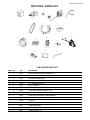
I. KEY SPARE PARTS KIT
ITEM QTY.
P/N
DESCRIPTION
1
1
47321
DIGITAL TEMPERATURE CONTROLLER
2
1
51067
CONVEYOR DRIVE MOTOR W/PICKUP ASSY.
3
2
30153
DRIVE MOTOR BRUSHES
4
1
60542
KIT, CONVEYOR SPEED CONTROLER
5
1
33984
KIT, THERMOCOUPLE 6″
6
1
50517
BELT, BLOWER
7
1
44687
MOTOR, BLOWER, 208/230V, 1/2HP
8
1
33983
HIGH LIMIT CONTROL MODULE, 240V
9
1
36451
COOLING FAN (BACKWALL)
10
1
97525
COOLING FAN (CONTROL COMPARTMENT)
11
1
60836
AIR SWITCH
12
1
48455
IGNITOR
13
1
60679
COMBINATION GAS CONTROL VALVE (SAFETY REGULATOR)
14
1
60671
AMPLIFIER BOARD
15
1
50239
IGNITION MODULE
16
1
50240
IGNITION CABLE, 25″
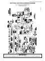
SECTION 6 - ELECTRICAL WIRING DIAGRAMS
SECTION 6 - ELECTRICAL WIRING DIAGRAMS
60968 Rev. D
Fig. 6-1 - Wiring diagram, PS536GS Gas Oven
208/240V, 50/60 Hz, 1 Ph
IMPORTANT
An electrical wiring diagram for the oven is also located inside the machinery compartment.
NOTES
NOTES
WARNING
Improper installation, adjustment, alteration, service or maintenance
can cause property damage, injury or death. Read the installation,
operating and maintenance instructions thoroughly before
installing or servicing this equipment.
NOTICE
During the warranty period, ALL parts replacement and servicing should be performed by
your Middleby Marshall Authorized Service Agent. Service that is performed by parties
other than your Middleby Marshall Authorized Service Agent may void your warranty.
NOTICE
Using any parts other than genuine Middleby Marshall factory manufactured parts relieves
the manufacturer of all warranty and liability.
NOTICE
Middleby Marshall reserves the right to change specifications at any time.
Middleby is proud to support the Commercial Food Equipment
Service Association (CFESA). We recognize and applaud
CFESA's ongoing efforts to improve the quality of technical
service in the industry.
Middleby Cooking Systems Group • 1400 Toastmaster Drive • Elgin, IL 60120 • USA • (847)741-3300 • FAX (847)741-4406
24-Hour Service Hotline: 1-(800)-238-8444
www.middleby.com