1
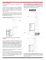
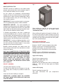
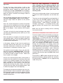
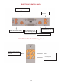
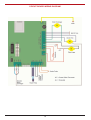
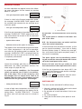
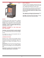
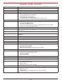
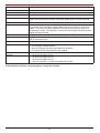
FUSION PELLET STOVE
Operating & Installation Manual
TABLE OF CONTENTS
PAGE
NO.
1.
Standards . . . . . . . . . . . . . . . . . . . . . . . . . . . . . . . . . . . . . . . . . . . . . . . . . . . . . . . . . . . . .
2
2.
Recommendations . . . . . . . . . . . . . . . . . . . . . . . . . . . . . . . . . . . . . . . . . . . . . . . . . . . . . .
2
3.
General Notice . . . . . . . . . . . . . . . . . . . . . . . . . . . . . . . . . . . . . . . . . . . . . . . . . . . . . . . . .
2
4.
Assembly & Installation Instructions . . . . . . . . . . . . . . . . . . . . . . . . . . . . . . . . . . . . . . . .
3
5.
Hearth Dimensions. . . . . . . . . . . . . . . . . . . . . . . . . . . . . . . . . . . . . . . . . . . . . . . . . . . . . .
3
6.
Stove Dimensions . . . . . . . . . . . . . . . . . . . . . . . . . . . . . . . . . . . . . . . . . . . . . . . . . . . . . .
3
7.
Safety Warnings. . . . . . . . . . . . . . . . . . . . . . . . . . . . . . . . . . . . . . . . . . . . . . . . . . . . . . . .
4
8.
Flue - Vertical External or Internal Chimney . . . . . . . . . . . . . . . . . . . . . . . . . . . . . . . . . .
4
9.
Combustion Air. . . . . . . . . . . . . . . . . . . . . . . . . . . . . . . . . . . . . . . . . . . . . . . . . . . . . . . . .
5
10.
Safety & Correct use of the Appliance. . . . . . . . . . . . . . . . . . . . . . . . . . . . . . . . . . . . . . .
5
11.
In Case Of Chimney Fire . . . . . . . . . . . . . . . . . . . . . . . . . . . . . . . . . . . . . . . . . . . . . . . . .
6
12.
Fuel
................................................................
6
13.
Pellet Loading . . . . . . . . . . . . . . . . . . . . . . . . . . . . . . . . . . . . . . . . . . . . . . . . . . . . . . . . .
6
14.
Notes on Operation . . . . . . . . . . . . . . . . . . . . . . . . . . . . . . . . . . . . . . . . . . . . . . . . . . . . .
6
15.
Operating Sequence & Switching Off . . . . . . . . . . . . . . . . . . . . . . . . . . . . . . . . . . . . . . .
7
16.
Electronic Control Panel . . . . . . . . . . . . . . . . . . . . . . . . . . . . . . . . . . . . . . . . . . . . . . . . .
9
17.
Remote Control Functions . . . . . . . . . . . . . . . . . . . . . . . . . . . . . . . . . . . . . . . . . . . . . . . .
9
18.
Circuit Board Wiring Diagram . . . . . . . . . . . . . . . . . . . . . . . . . . . . . . . . . . . . . . . . . . . . .
10
19.
Managing Alarms . . . . . . . . . . . . . . . . . . . . . . . . . . . . . . . . . . . . . . . . . . . . . . . . . . . . . . .
11
20.
Switching Off . . . . . . . . . . . . . . . . . . . . . . . . . . . . . . . . . . . . . . . . . . . . . . . . . . . . . . . . . .
11
21.
Safety Devices . . . . . . . . . . . . . . . . . . . . . . . . . . . . . . . . . . . . . . . . . . . . . . . . . . . . . . . . .
12
22.
Cleaning Of The Stove. . . . . . . . . . . . . . . . . . . . . . . . . . . . . . . . . . . . . . . . . . . . . . . . . . .
12
23.
Ashpan & Burn Pot . . . . . . . . . . . . . . . . . . . . . . . . . . . . . . . . . . . . . . . . . . . . . . . . . . . . .
12
24.
Cleaning The Ashpan . . . . . . . . . . . . . . . . . . . . . . . . . . . . . . . . . . . . . . . . . . . . . . . . . . .
12
25.
Glass . . . . . . . . . . . . . . . . . . . . . . . . . . . . . . . . . . . . . . . . . . . . . . . . . . . . . . . . . . . . . . . .
13
26.
Periodic Cleaning Of Stove & Heat Exchanger . . . . . . . . . . . . . . . . . . . . . . . . . . . . . . . .
13
27.
Cleaning The Flue . . . . . . . . . . . . . . . . . . . . . . . . . . . . . . . . . . . . . . . . . . . . . . . . . . . . . .
13
28.
End of Season . . . . . . . . . . . . . . . . . . . . . . . . . . . . . . . . . . . . . . . . . . . . . . . . . . . . . . . . .
13
29.
Problems / Causes / Solutions. . . . . . . . . . . . . . . . . . . . . . . . . . . . . . . . . . . . . . . . . . . . .
14
30.
Technical Information . . . . . . . . . . . . . . . . . . . . . . . . . . . . . . . . . . . . . . . . . . . . . . . . . . . .
16
1
STANDARDS
N.B.: The information in this manual is given only as a general guide, and local, national or EC regulations
must also be complied with.
RECOMMENDATIONS:
Before using this appliance, please read all parts of this instruction manual carefully, as the information it
contains, is essential in order to use the appliance correctly.
Read this manual prior to installation, maintenance & operation of this appliance.
The manufacturer will not be responsible for any modifications made to this appliance by or on behalf of the
user. The manufacturer will not be responsible for any eventual damage or loss as a result of unauthorised
modifications. In the event that parts need to be replaced, only use parts recommended by Aga.
The user is responsible for all work involved in the initial installation of the appliance and for keeping it
working efficiently thereafter.
Incorrect installation may result in damage to property, or injuries to persons or animals. The manufacturer
will not be liable for any damage resulting from incorrect installation, or failure to follow the instructions that
accompany this appliance.
GENERAL NOTICE
Important: The appliance MUST be earthed.
Before installing the appliance, the power supply system must be checked to ensure it has an effective
earth circuit.
Important: the power supply cable must be of sufficient cross-section for the power requirement of the
appliance.
The supply voltage required for the stove is 220-240 V at 50 Hz. Voltage variations greater than 10% of the
rated value may cause irregular operation, or damage to the electrical system. The appliance must be positioned so that the domestic power supply plug remains accessible.
If the power supply cable becomes damaged, switch off the power and have it repaired by an authorised
Aga service agent.
Do not use a flexible liner to connect this appliance to a flue system.
2
ASSEMBLY AND INSTALLATION
INSTRUCTIONS
STOVE DIMENSIONS (MM)
Fig.3
N.B. To install the stove, use only authorised and
trained personnel, or contact the dealer.
1. Check that the floor can support the total weight
of the stove (140kgs).
2. Refer to the figure that shows the dimensions
of the flue pipe, and allowing for the thickness
of the floor-protection base (if applicable), make
a hole in the chimney to accommodate the
smoke outlet pipe (diameter 80 mm).
3. Connect the stove to the chimney with a certified steel pipe suitable for this use and seal it.
This appliance must not be connected to a
shared flue.
4. Leave adequate clearance around the stove for
cleaning and servicing. If the appliance is to be
installed in an alcove a minimum of 400mm
clearance is required all round to allow access
for cleaning and servicing. This appliance has
adjustable legs
Fig.4
Fig.1
1040
650
HEARTH DIMENSIONS
Fig.5
The hearth should extend 150mm to the rear of the
stove and 150mm to both sides and 30cm to the
front.
Fig.2
Min 150mm
Flue Outlet
190
Min 300mm
Min 150mm
210
Min 150mm
3
The through-holes in walls or floors must always
have an insulated tube or ventilation passage, so
that it is always possible to disassemble the chimney components for cleaning and inspection, and to
prevent contact between these components and
wall masonry or inflammable surfaces.
SAFETY WARNINGS
This appliance is not suitable for connection to a
shared flue.
The stove must be placed on a non combustible
hearth. If it is to be supported on a combustible floor
surface, it must be supported on a floor-protection
plate of at least the size shown in 3.1. It must be at
least 8mm thick.
2300
Fig.7
The appliance must be connected to a chimney
suitable for solid fuels with a minimum diameter of
80 mm, and with a minimum height of 2.00 m from
the appliance flue outlet.
For insulating and sealing the pipes, use only heatresistant materials (250° C).
Fig.6
Min. 2 meters
Fig.8
600
FLUE - VERTICAL EXTERNAL OR INTERNAL
CHIMNEY
The flue arrangement shown is the best solution for
evacuating smoke, even when the ventilator is off
(no power supply, or lock out flame). Any installation
must comply with current building regulations.
The minimum 2.00 metre level difference between
the roof outlet and the T fitting inside or outside the
building, ensures a minimum vacuum inside the
stove, thus preventing smoke issue into the room.
External flues must be insulated: for example by
using double-wall flue pipes.
The figure shows the recommended arrangement
for flue outlets above roof level. In all cases, there
must be a T fitting with inspection plug. The flue
duct must be suitably fastened and fitted with a
chimney pot for rain protection.
It is useful to have planned inspections of the pipe
bends for periodic maintenance of the flue duct.
The smoke outlet pipe must be protected against
rainwater ingress.
4
Where it is necessary to have a horizontal length of
pipe, there must be a minimum positive gradient of
3% along its length.
SAFETY AND CORRECT USE OF THE APPLIANCE
Before switching on for the first time, read the following safety instructions.
Do not run flue pipe in a horizontal plain or in a
reverse gradient.
1. Some parts of the stove become hot (door,
glass, flue, etc.), and contact with these parts
may cause burns.
Do not install the smoke outlet at pavement level,
on public streets, car-parks or anywhere that might
cause annoyance to people and/or animals.
2. Do not place combustible or inflammable
materials beside the stove, and never at less
than 1 metre.
The flue must be installed with the outlet above roof
level complying with current building regulations. A
maximum flue length of 8 metres is allowed. for
each 90o bend or T fitting, reduce the length by one
metre. A minimum flue draught of 10 Pascals is
required.
3. Do not store bags of pellets close to the stove.
4. Your stove burns pellets only - it is not an incinerator. It is forbidden to burn other materials or
household waste as fuel.
IMPORTANT: All sections of the flue pipe must be
accessible for inspection, and allow for internal
cleaning, removal or substitution.
5. When loading pellets into the tank, avoid pour
ing sawdust along with them. Failure to follow
this instruction may make the appliance unsafe,
and void all warranties.
Do not place a net or grill over the flue outlet. When
they become dirty they will obstruct the outlet and
cause poor combustion, and the stove may be
blocked with soot.
6. Keep children away from this the stove. Do not
open the door when the stove is lit.
COMBUSTION AIR
7. Do not switch off the electric power supply
while the stove is on. This will cause the smoke
extractor fan to stop, and the burning fuel will
cause smoke to issue into the room if there is
no natural upward draught in the chimney.
The process of combustion requires oxygen, and
therefore air. When in operation, the stove draws air
from the room in which it is installed; poor combustion may therefore result if the room is insufficiently
ventilated.
8. When the stove is lit for the first time, the varnish may release fumes, and these may emit
an unpleasant odour. The room must therefore
must be ventilated to evacuate these fumes.
The varnish will be fully hardened after several
heating cycles (2-3). On first lighting the stove
may lockout as there is no pellet in the feed.
The display will show ALARM NO FIRE. The
stove has to be switched off and on again to
reset.
To resolve this problem, a suitable vent hole must
be provided to allow a permanent supply of fresh air
from the outside. The cross-section of the vent must
be 6 cm² for each kW of energy consumed at maximum input therefore the ventilation hole must have
a cross-sectional area of 83 cm² if a flue draught
stabiliser is fitted.
If no flue draught stabiliser is fitted the ventilation
requirement is 44cm².
9. Periodically ensure that the gaskets between
stove and flue pipe are gas tight.
If the stove is located in a room containing another
appliance cooker hood or extractor fan, it is essential to provide ventilation equivalent to the sum of
the air requirement for all appliances.
10. In case of fire, switch off the stove, move any
flammable materials away, and call the fire
services.
The vent must not be placed directly beside the
appliance in order to avoid drawing in air that is too
cold: at certain times of the year when the appliance is very cold, the stove may be locked out
when you first attempt to light it. If this occurs, the
situation should be considered absolutely normal,
and you can unlock the stove using the switch #4
located on the control panel. Then switch on again.
IN CASE OF CHIMNEY FIRE
Switch off appliance and close all openings into the
stove, watch for ignition of adjacent combustibles
from hot embers or sparks from chimney.
5
FUEL
Fig.9
WHAT ARE PELLETS?
PELLETS consist of sawdust or real wood scraps
ground and pressed into small cylinders about 6
mm in diameter and 20-30 mm in length.
As fuel, pellets are completely environmentally
friendly, as they are made entirely of natural wood,
without glue or other chemical compounds. Pellets
have a high calorific value (4.7 to 5.3 kW/kg), and
low moisture content.
IMPORTANT: Pellets must be stored in a dry place.
Use only good quality pellets, without sawdust.
IMPORTANT NOTICE: The small quantities of
sawdust normally present at the bottom of the bags
should not be emptied into the tank, but should be
held inside the bag while pouring the pellets carefully so that the sawdust remains inside.
When pellets are used up, the stove cannot work
and is therefore locked out, the display shows
“ALARM NO FIRE”.
If sawdust accumulates in the tank, it should be
removed periodically with a vacuum cleaner (with
the door open and disconnecting the power plug
from the electricity supply), to prevent it entering the
loading system and causing serious malfunctions.
When refilling with pellet at this point it will take a little while for the pellet to come through so the fire
may go to lockout again. This is normal and will light
normally once the pellet has started to feed, probably at the second attempt.
IMPORTANT: If, during a loading operation, or for
any other reason, foreign matter is allowed to enter
the tank and then the pellet loader, it may cause
damage to the internal mechanisms.
NOTES ON OPERATION
Description of front panel controls
Button 4: ON/OFF and exit programming mode
Button 3: press once to change temperature
settings, then button 1 to raise and 2 to lower.
Buttons 5 and 6: UP/DOWN for thermal power
setting
Buttons 2 and 1: UP/DOWN for temperature
setting, programming functions and indicators
Besides causing damage, this would cause the
stove to stop. In this case, the manufacturer cannot
accept any liability.
ONLY 6mm DIAMETER PELLET MUST BE USED
DO NOT USE POOR QUALITY PELLETS OR REPROCESSED PELLETS WITH HIGH SAWDUST
CONTENT. THIS TYPE OF PELLET CAN SERIOUSLY IMPAIR THE FUNCTIONS IN YOUR
STOVE, VOID THE WARRANTY AND THEREFORE RELEASE THE MANUFACTURER FROM
ALL LIABILITY.
Upper LED display
Top left: timer program active
Bottom right: pellet auger ON
Top right: (not active)
Bottom left: this will flash when stove is cooling after
being lit. Wait until this lamp goes out before
restarting.
PELLET LOADING
The pellet tank capacity is 25 Kg.
To load, lift the pellet tank lid, and pour in the pellets, taking care to keep any sawdust inside the
bags.
Lower LED display
Top left: heating elements ON
Top right: thermostat ON (set temperature
achieved)
Close the lid when loading is complete.
IMPORTANT: LOADING MUST BE CARRIED
OUT ONLY WHEN THE STOVE IS OFF AND HAS
COOLED DOWN.
6
When the room temperature is reached, the
stove changes from the working program into
ECO mode (pilot flame). ECO mode is the same
power as heat setting 1. When ambient temperature falls by 2°C, the stove goes back into
working mode.
Operation:
To start the stove, press button 4; after a few
moments, the control unit puts the stove into the
pre-ignition phase, lighting the igniter plug and
showing the message “FAN CAND” on the display;
it also switches the extractor fan on at maximum
power for about 5 seconds, then brings it down to
ignition power.
When not in setting mode, button 1 can be pressed
to show the smoke temperature on the lower display.
After this phase (which lasts about 90 seconds), the
message “LOAD WOOD” appears on the display
and the auger loads the pellets at the pre-set
speed.
The stove can be switched off by pressing button 4;
in this case, the word OFF appears on the upper
display, pellet flow is stopped and extractor fan
speed increases. When cooling is complete, the
ventilator (exchanger) is switched off and, after
several minutes, the extractor fan is also switched
off.
When the smoke temperature reaches the ignition
value set by the manufacturer, the stove goes into
stabilization phase and shows the message “FIRE
ON” on the display. It then switches off the igniter
plug.
N.B.: when the stove is cooling, the fan is working
for several minutes.
The room air fan for the heat exchanger also starts
up during the stabilisation phase and may run fast
for a short time.
OPERATING SEQUENCE AND SWITCHING OFF
To start or stop the stove press button 4 on the control panel. On starting, the message FAN CAND is
displayed for 1.5 minutes and then the message
LOAD WOOD appears for 4-5 minutes. During this
time the burn pot will be lit and the flame stabilised.
Finally the message FIRE ON appears for 3 minutes. The starting time takes about 10 minutes.
During this initial phase, the display shows the
working programme and can be modified using buttons 5 and 6 on the control panel. To set the desired
room temperature use buttons 1 and 2. When the
programming phase is complete the stove continues working until the selected room temperature is
reached, then the stove goes into ECO mode (small
pilot flame).
When this phase is complete, the control unit goes
into working mode, in which the display shows the
selected thermal power value (set by buttons 5 and
6) and ambient temperature.
In this phase, buttons 5 and 6 can be used to set
the power output of the stove from 1 to 5, provided
that room temperature is below the set value, otherwise power is reduced to minimum value.
If the pellets are not lit within 15 min., the stove displays the message “ALARM NO FIRE”. This is normal at first start up or if the auger has run out of pellet. Switch off and on again to reset. Make sure
there is pellet in the hopper.
Press button 3, SET to page through the timer programming functions and to confirm the selection.
Pressing button 4 ON/OFF will exit programming
mode at any time.
If there is an electrical power failure, when power is
restored, the stove expels the remaining smoke and
resumes the working program from the point at
which it stopped. It can do this only if the electrical
power was lost for a few minutes. If the stove has
cooled down during the power failure, the control
unit puts the stove back into the ignition phase, and
re-starts the program from the beginning.
To change the temperature setting at any time, simply press button 3 and use buttons 2 and 1 to adjust
the temperature shown on the lower display. During
the operating phase, the lower display indicates
ambient temperature.
7
Display Shows
Action
UT01
Set the current day. If today is Monday then using
buttons 1 & 2 set to DAY 1. If Wednesday, set to DAY 3.
UT02
Current clock time in hours using 24 hour clock. (4pm = 16)
UT03
Current clock time in minutes (0-59)
UT04
Not used
UT05
ON time (first event setting)
UT06
OFF time (first event setting)
UT07
Day for programme to run. For Monday to Friday working,
set Day 1 ON, Day 2 ON, Day 3 ON, Day 4 ON, Day 5 ON
and Day 6 OFF, Day 7 OFF. The stove will not function on
Saturday and Sunday. To only run on Saturday/Sunday set
Days 1-5 to OFF and Days 6-7 to ON.
UT08
ON time (Second event setting)
UT09
OFF time (Second event setting)
UT10
Day for programme to run (As UT07)
If it is required for the stove to run all day using only
one event from say 0800 to 2000 then set UT05 to
0800 and UT06 to 2000. Select the day using
UT07. At UT10 set all days used at UT07 to off.
When using two event programming allow at least
30 minutes between the end of the first event to the
start of the second event.
When the stove is off, pressing and holding button
1 or 2 will show the heat setting of the stove when
lit. This will either display ECO if the room temperature is at or above the set temperature or the heat
setting 1-5 as previously set.
If the flue gas temperature rises above 260°C, the
stove goes into economy mode and the message
ECO is displayed. This message is also displayed
when the selected room temperature has been
reached.
If the stove is not required to work automatically set
UT01 to OFF. In this case the stove ignores all other
settings and will maintain the set room temperature.
If the remote thermostat is connected this will take
priority for the temperature setting.
8
ELECTRONIC CONTROL PANEL
Access to timer-thermostat
and clock programmer
Power increase
from 1 to 5
Room temperature setting
The display shows the
stove operating phases
Power decreases from 5
to 1
Stove On/Off control
REMOTE CONTROL FUNCTIONS (optional)
The stove is switched on/off by
pressing buttons 1 and 6 at the
same time.
Program selection
buttons:
6: Increase power
5: Decrease power
9
CIRCUIT BOARD WIRING DIAGRAM
10
MANAGING ALARMS
Fig.10
An alarm indication may appear in one of the following cases (the alarm can be cleared by pressing
button 4 “ON OFF”:
ALARM
-
Flue gas temperature probe alarm
SOND FUMI
1. Unscrew the cap
anticlockwise
If there is a fault in the flue gas temperature probe,
the message “ALARM SOND FUMI” appears and
the ventilator and extractor fan are switched on at
maximum speed.
-
Flue gas over-temperature alarm
ALARM
HOT TEMP
2. Push The Button
If the flue gas temperature rises above 280° C, the
message “ALARM HOT TEMP” appears and ventilator and extractor fan remain lit until the decrease
of flue temperature.
ATTENTION: the thermostat has to be reset by
hand.
The control panel is situated in the lower rear
part of the stove.
ALARM
-
-
Ignition failure alarm
NO FIRE
N.B. the thermostat does not unlock until the
stove has cooled completely.
Extractor alarm (if this option is available)
If the thermostat reset has been successful, a click
can be heard immediately. Also refer to Safety
Devices Section 4 page 13. Before every new ignition, verify that the burn pot is completely empty; if
not, clean it immediately.
This appears if the initial attempt to ignite has failed,
or if stove temperature is too low for operation,
even after the full ignition period has elapsed. The
message “ALARM NO FIRE” is displayed and the
extractor fan runs for a pre-set time until the stove
is completely switched off.
The alarm signals can be cancelled by switching off and on the stove with button No.4 situated in the frontal panel of the stove.
ALARM
-
Pressostat alarm
DEP FAIL
Incase the exchanger gets dirty or the chimney is
obstructed, the safety pressostat switches the
motor auger off (stops the fuel).
Ensure Air Inlet and flue gas outlet are clear
from obstructions before operation of the stove.
If the flue gas temperature rises above 260°C, the
stove goes into Economy mode and the message
ECO appears on the display.
The message ECO also appears when the selec-
In certain weather conditions, the Pressostat
switch can operate even if there is no malfunction of the stove. This can be caused by a low
flue draught. This is a normal event. There is no
problem with the stove. If the problem persists
check the flue for gas tightness and draught.
ted room temperature has been reached.
SWITCHING OFF
ALARM
-
Safety thermostat alarm
The stove can be switched off in different ways:
SIC FAIL
1. Manually (putting the On/Off switch on the back
of the stove in the Off position).
2. By actuation of a room thermostat, if this is connected.
3. By a timer program.
4. Using the remote control (if this option is available).
In case of high stove temperature, the safety thermostat operates and shows on the display the following notice: “ALARM TERM SICC”. To restart
the stove, wait until cool and reset it as shown in
Fig 10.
11
5. Temporary Electrical Power Failure
N.B.: Method 1 is used to carry out maintenance or
to switch off the stove permanently at the end of the
cold season. Never switch off the stove while it is in
operation, either by cutting off the current at the
plug or at the switch located on the back of the
stove.
If there is a temporary power failure while the stove
is in operation, the appliance will come on again
automatically. If the power failure is longer lasting,
the smoke extractor stops running and the stove
may therefore emit smoke into the room.
This will cause the smoke extractor fan to stop
immediately, causing smoke to issue into the room
if there is no natural upward draught in the chimney.
6. Electrical Safety
The stove is protected by a main fuse located on
the rear panel.
After switching off the stove on the front panel,
or using the remote control (if this option is
present), wait for 15 minutes cooling time to
elapse before attempting to start again. The
stove may not re-light if it has not cooled sufficiently.
CLEANING OF THE STOVE
IMPORTANT: before starting to clean the stove,
check that it is switched off and completely cooled
and that the electrical power supply is disconnected.
During the switch-off phase, the smoke extraction
motor continues to run until the stove is cooled,
then switches off automatically. Similarly, the room
air ventilator continues running until the stove has
cooled (the ventilator may switch off and then on
again if there is still some heat in the stove).
ASHPAN AND BURN POT
WARNING: Do not vacuum hot cinders as they
may cause a fire in the cleaner.
The burn pot must be cleaned everyday. Pull it out
manually by lifting, and empty the accumulated ash.
When re-inserting the burn pot, check that it is the
right way around, with the hole for the igniter plug
facing towards the inside of the stove.
SAFETY DEVICES
1. Flue Gas Extraction Motor Failure
If the flue gas extractor stops, a pressure switch
immediately stops the pellet supply.
Every two or three days, clear the grid at the bottom
of the combustion chamber, take out the drawer,
empty it and replace in the correct position. Finish
off cleaning the inside of the chamber using a vacuum cleaner. We recommend emptying the lower
ashpan periodically, as described in the following
paragraphs. It may be necessary to vacuum the
small chamber beneath the burn pot.
2. Flue Gas Outlet Safety Device
If the flue gas outlet is obstructed, the pressure
switch prevents fuel from entering the burn pot.
3. Pellet Loading Gear Motor Failure Or
Blockage
IMPORTANT: All cleaning and maintenance operations must be carried out when the stove is cold.
These cleaning operations ensure that the appliance continues to work efficiently and correctly.
The required frequency of cleaning operations
depends very much on the quality of the pellets
used. We recommend using only tested, good-quality pellets.
If the gear motor stops, the stove continues to operate until it starts to cool down. The system will
attempt to start up the stove, and if the fault persists
the stove will stop completely and lock out.
4. Hot Air Distribution Ventilator Failure
When the temperature at the end of the loader
reaches 105°C, a safety thermostat stops the gear
motor, causing the stove to switch off.
After the cold season has ended, the exchanger
must be cleaned. This operation may be required
more often, depending on the pellet quality, but this
should not be considered a sign that the stove is not
functioning correctly.
If the thermostat is activated, it must be reset using
the special control (protected by a screw plug) on
the back of the stove under the main switch and
protection fuse.
CLEANING THE ASHPAN
If the thermostat is actuated again and causes
the stove to stop, contact the technical support
service immediately.
Open the panel, remove the ashpan, empty it and
re-insert correctly. This operation is usually carried
out once per week, and more often if required.
12
END OF SEASON
Fig.11
We advise using up all pellets remaining in the tank
in order to prevent condensation from forming and
thus clogging and blocking the feeder motor.
Pellets and sawdust remaining at the bottom of the
tank should be removed using a vacuum cleaner.
If there are substantial amounts of sawdust, we recommend checking the quality of the pellets used to
fuel the stove.
This operation is carried out with the stove off and
cool, and the power supply plug disconnected.
CAUTION: Do not vacuum hot cinders as they
may cause a fire in the vacuum cleaner.
GLASS
The glass will self clean when there is sufficient
heat generated by the burning fuel. If a build-up of
deposits occur on the glass it may be due to draft
conditions, poor quality fuel or very low burning for
a long time. It is best to clean the glass when it is
thoroughly cooled. A deposit of ash will usually
wipe away with a dry cloth.
PERIODIC CLEANING OF THE STOVE AND
HEAT EXCHANGER
The stove and heat exchanger must be cleaned
periodically, and exclusively by authorised personnel. You should therefore call the technical support
service.
We suggest you carry out this operation after the
cold season has finished.
CLEANING THE FLUE
Whenever this is found to be necessary (and at
least once a year) vacuum and clean all flue ducts
to prevent the build up of particulate matter. It is
important not to obstruct the passage of the flue
gasses.
IMPORTANT: Ensure that the flue pipe gaskets are
gas tight. Where they are not in good condition
replace them immediately. Do not use flexible flue
pipe.
FAILURE TO CLEAN THE FLUE MAY AFFECT
THE SAFE OPERATION OF THE STOVE.
13
PROBLEMS - CAUSES - SOLUTIONS
PROBLEM / CAUSE
SOLUTION
Problem
Pellets not delivered into burn pot
Causes
*
*
*
*
*
Tank is empty
Flue gas extractor fan is not working
Auger blocked by foreign objects
No electrical power to control panel
Flue obstructed causing differential pressure switch lock out
Solutions
*
*
*
*
*
Re-fill the tank
Call technical support service
Call technical support service
Check that the power plug is correctly inserted and that the fuse is good
Clean all the smoke outlet pipe and flue
Problem
When switched on, the stove functions for a few minutes then is switched off by a
safety device.
Cause
The outlet fumes are not reaching the minimum temperature required to switch off
the igniter.
Solution
Check that the burn pot is clean
Problem
Flame is too smoky
Causes
*
*
*
*
Insufficient combustion air as the air holes in the burn pot are obstructed
Flue obstructed or clogged.
Stove and exchanger dirty
Pellets are poor quality or contain too much moisture.
Solutions
*
*
*
*
Clean the burn pot
Clean the flue gas outlet pipe and flue
Clean the exchanger
Replace the pellets
Problem
Flame does not ignite
Causes
*
*
*
*
Air inlet clogged
Ash present in the burn pot
Pellets used up
Differential pressure switch activated
Solutions
*
*
*
*
Check that the air inlet is clean and not obstructed
Clean the burn pot
Re-fill the tank
Clean the flue gas outlet pipe and flue or close main door
14
PROBLEM / CAUSE
SOLUTION
Problem
Pellet loader blocked
Causes
Poor quality pellets, sawdust included accidentally or pellet stuck and obstructing the
feeder slide to the burner, possibly causing the loading auger to become blocked.
Solutions
The problem can often be resolved without calling technical support, simply by inserting a flexible steel rod inside the pellet loading tube once the stove is off and has
cooled. In this way, the blocked pellet can be made to fall into the burn pot, thus
unblocking the auger. This operation is carried out with the stove off and the power
supply plug disconnected.
Problem
While the stove is in operation, the pellet loading indicator light comes on, but no pellets fall into the burn pot.
Cause
*
*
*
*
Air exchanger ventilator dirty
Air exchanger ventilator broken
Stove overheating and safety thermostat was activated
Flue obstructed or draught diverter grill clogged
Solution
*
*
*
*
Call technical support service
Call technical support service
Call technical support service
Clean the whole flue - remove draught diverter and grill
If the problem cannot be resolved, please contact the Installer.
15
FUSION PELLET STOVE TECHNICAL DETAILS
Max. fuel consumption per hour
kg/h
2.9
Maximum input
kW
14.4
Minimum input
kW
4.4
Maximum output
kW
13.0
Minimum output
kW
4.1
Efficiency
%
90.4
Minimum air requirement for combustion
m3/h
33
Flue gas mass flow rate
gr/s
9.4
maximum power
o
C
155
minimum power
o
C
75
mbar
0.1
pascal
10
Elect. power consumption during ignition*
W
260
Elect. power consumption during operation
W
91
Flue gas temperature
Minimum draught of fireplace
Power Supply
V/Hz
230/50
Width
mm
590
Height
mm
1050
Depth
mm
540
Net weight
kg
115
Pellet tank capacity
kg
25
Total Weight
kg
140
Diameter of flue gas outlet
mm
80
Diameter of combustion air inlet pipe
mm
30
Features
Flue outlet pressure switch
Ashpan
Self-cleaning glass
Forced ventilation
Adjustable feet
Pre-equipped for connection to room thermostat
* Power consumption during first 10 minutes of operation
Aga,
Station Road,
Ketley, Telford,
Shropshire, TF1 5AQ,
UK
16
Rev:00 1 DP 080807