1
Installation
Instructions
Millennia ® Electric Range
For use with model MRES30
SAVE AND READ THESE INSTRUCTIONS
CONVENTIONS
USED IN THESE INSTRUCTIONS
I
I
WARNINGS:
Must be followed carefully to avoid personal injury or damage.
NOTES:
Contain helpful hints and tips to facilitate
the installation.
IMPORTANT
1.
2.
3.
4.
5.
Before beginning installation, please thoroughly read and become familiar with these instructions.
Installation and service must be completed by a qualified installer or service agency.
Installer: Please leave these Installation Instructions with the owner.
Owner: Please keep these instructions for local electrical inspector's use and for future reference.
Read the accompanying use and care manual prior to operating this appliance.
TABLE OF CONTENTS
Important Safety Instructions ..........................................................................................................................
Page 1
Electrical Power Supply Requirements ..........................................................................................................
Page 2
Product Dimensions .........................................................................................................................................
Page 2
Planning the Location ......................................................................................................................................
Page 3
Cabinet and Countertop Preparation ..............................................................................................................
Page 3-4
Verifying the Package Contents ......................................................................................................................
Page 5
Installing the Anti-tip Bracket ..........................................................................................................................
Page 5
Removing the Oven Door .................................................................................................................................
Page 5
Removing the Kick Panel .................................................................................................................................
Page 5
Electrical Connection ........................................................................................................................................
Page 5-6
Installing the Range ...........................................................................................................................................
Page 7
Re-installing the Oven Door ..............................................................................................................................
Page 7
Verifying Proper Operation ................................................................................................................................
Page 7
Part No. 65166
Rev. K
IMPORTANT SAFETY INSTRUCTIONS
1.
WARNINGS:
Read all instructions before
using the appliance.
.
If the information in this
manual is not followed exactly,
a fire or explosion may result
causing property damage,
personal injury, or death.
.
Improper installation,
adjustment, alteration,
service or maintenance can
cause personal injury or
property damage. Refer to
these instructions and the
accompanying use and care
manual. For assistance or
additional information, consult
a qualified installer, service
agency or dealer.
.
For your safety:
Do not store or use gasoline
or other flammable vapors and
liquids in the vicinity of this or
any other appliance.
Do not obstruct the flow of
ventilation air to the unit.
Keep appliance area clear and
free from combustible material.
.
This appliance must not
be used in combination
with surface (countertop)
ventilation systems. The use
of an overhead hood, or Dacor
raised vent is recommended
for ventilation.
6.
Disconnect the electrical
supply before installing or
servicing the appliance.
.
8.
1
This appliance must be
grounded. Connect only to a
properly grounded electrical
supply. Refer to "Electrical
Requirements."
Install or locate this appliance
only in accordance with these
installation instructions.
_acar
.
Use this appliance only for
its intended use as described
in this manual. Do not use
corrosive chemicals or vapors
in this appliance. This type of
appliance is not designed for
industrial or laboratory use.
10. As with any appliance, close
supervision is necessary
when used by children.
11. Do not operate this appliance
if it has a damaged electrical
cord, plug, conduit or wires,
if it is not working properly,
or if it has been damaged or
dropped.
12. Installation of this appliance
must be performed by a
qualified installer or service
agency.
13. This appliance should be
serviced only by qualified
service personnel. Contact the
nearest DACOR authorized
servicer at (800) 793-0093,
or at www.Dacor.com for
examination, repair or
adjustment.
14. Some products, such as whole
eggs, and sealed containers,
such as closed glass jars, may
explode and should not be
heated on this cooktop.
WARNING:
NEVER cover any slots, holes
or passages in the oven bottom
or cover an entire rack with
materials such as aluminum
foil. Doing so blocks air flow
through the oven and may
cause a fire hazard. Aluminum
foil linings may also trap heat,
causing a fire hazard.
WARNING:
NEVER use this appliance as a
space heater to heat or warm
the room. Doing so may result
in overheating of the appliance.
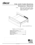
Range Data Plate Location
The range data plate specifies the model
number, serial number and electrical
supply requirements. It is located on the
left side wall inside the range storage
compartment.
<
Product Dimensions
Electrical Power Supply
Requirements
It is the owner's responsibility to ensure
that the electrical connection of this
appliance is performed by a qualified
electrician. The electrical installation,
including minimum supply wire size and
grounding, must be in accordance with
the National Electric Code ANSI/NFPA
70-2002* (or latest revision) and local
codes and ordinances.
60" (1524mm)long
240 Vac 4 wire
conduit
Optional full
size side
*A copy of this standard may be obtained
from:
National Fire Protection Association
1 Batterymarch Park
Quincy, Massachusetts 02269-9101
The correct voltage, frequency and
amperage must be supplied to the
appliance from a separate, grounded,
circuit that is protected by a properly sized
circuit breaker or time delay fuse.
Dedicated
Electrical
Circuit
location
!
35"
'!
(889mm)_
5/16"- 1 13/16"
(8- 46mm)
Total
Connected
Required
Load
120/240Vac,
4-wire, 60Hz., 50Amp.
10.3kW (48.2Amp.)
Removable
(factory
3" (76mm) side panels
Electrical
Requirements
The above electrical specifications are for
reference only. See the range data plate
for exact specifications. See page 1 for
location.
Dimensions - Isometric View
30"
[_
WARNING:
(762mm)
If the electric service provided
does not meet the product
specifications, do not proceed
with the installation. Call the
selling dealer or a licensed
electrician.
NOTE:
If the appliance is connected
to a 120/208 volt power supply,
preheat times and cavity
temperature recovery times will
be increased slightly.
23
(59
Range top
2"
Im)
_.5._'16"
345 rim',
Rear of control
Panel/oven door
/
Door opened
Max. depth
to oven door
handle with
door closed
45 1/4"
(1149mm)
1
Dimensions
- Top View
_acar
2
Planning the Location
NOTE:
The shaded areas shown in the
illustrations, denote the location
of the electrical junction box/
receptacle. This is the suggested
location. For replacement
purposes, the location of the
existing electrical supply may be
utilized provided that it does not
interfere with the sides or rear of
the range. Verify that the electrical
service meets local building
codes.
The electrical junction box/receptacle must
be located so that it does not interfere
with the range when it is installed and
under operation• In addition, the junction
box must be located so the range can
be removed for service when the conduit
supplied with the unit is attached to the
junction box. Do not lengthen the conduit
or wiring provided with the range•
All dimensions shown are based on
standard American cabinets 36 inches
(914mm) high at the finished countertop
by 24 inches (610mm) deep, with a 25
inch (635mm) overall countertop depth•
When installing the range into nonstandard
cabinets, minimum clearances shown in
the diagrams must be maintained•
Cabinet and Countertop Preparation
NOTES:
1.
.
If cabinet storage space is to
be provided directly above
the range, the risk of personal
injury may be reduced by
installing a ventilating hood
that projects horizontally a
minimum of 5 inches (127mm)
beyond the face of the
cabinets.
The range may be installed
flush to the rear wall. We
recommend installing a noncombustible material on the
Access to the remote circuit breaker panel/
fuse box, with the range in place and
operating, must also be allowed for in
the installation• Any openings in the walt
behind the appliance and in the floor under
the appliance must be sealed•
rear wall above the range
and up to the vent hood. It
is not necessary to install
non-combustible materials
.
behind the range below the
countertop height.
The minimum distance from
the sides of the range above
the countertop to combustible
side walls must be at least 10
inches (254mm).
36" (914mm) Recommended .___
30" (762mm) Min.
Utilities may be located:
1.
2.
Hood
Contact your local building department
to verify compliance with local code
interpretation•
13"
(330mm
Max.
10" (254mm) Min.
to combustible side
walls above the range
(both sides)
Freestanding
3
_acar
In the lower left corner of the adjacent
right cabinet• (Recommended)
Alternate location, in the lower right
corner behind the range•
Cabinet Dimensions and Clearances
to Combustible
Surfaces
Cabinet and Countertop Preparation
(Continued)
Backsplash.
I\"
/"
""
""
I
I
!
1/4" (dmm
Vertical
non-combustible
Min. flat ledge
surface rear wall %,
/
_'-.h._
_-"_
Rear wall _,
",,"
',
i
I-" /
\
i
I
Adjust for backsplash
_[_
thickness
13/16" to 4 1/4"
_(21
- 108mm)
........................................
28 11/16" (729mm)
"_
29 5/8" (752mm)
,.
11/16"
(17mm)
Top View - Slide-In, Self-Rimming Installation using 3" Side Panels
(Part Numbers ARSR30 and ARSL30) with Backguard Removed
Vertical
non-combustible
surface rear wall __
_
27 7/8" (708mm)
,,
'_I
Backsplash
thicker than
3/4" (19mm)
s--_--"'-,,
$
"
,
_1
27 13/16"
(706 i)
,'
1 /4 " (6 ...... ) \ \
Min. flat ledge
$1
"t
',
--LL._.
",,
I
,"
, ,,
Adjust for backsplash
over 3/4" thick
.........
13/32" (10mm)
\
from 13/16" to 3 13/16"
(21 - 97mm)
=
29 1/4" (743mm)
30 1/16" (764mm)
Countertop overhangs cabinet
10" (254mm) Min.
to combustible side
walls above the range
(both sides)
Top View - Downdraft ERV30 with Slide-In, Self-Rimming Installation using 3" Side Panels
(Numbers ARSR30 and ARSL30), with Backguard Removed
dacar
4
Removing the Oven Door
WARNING:
This appliance must be installed
by a licensed plumber or gas
fitter when installed within the
Commonwealth of Massachusetts.
WARNINGS:
1.
Verifying the Package Contents
If any item is missing or damaged, please
contact your dealer immediately. Do not
install a damaged or incomplete appliance.
•
•
•
•
•
•
Electrical Connection
Use and care manual
Anti-tip bracket
Broiler grill and pan
Oven racks
Razor blade scraper
Dacor Cooktop Cleaning Cream
.
NOTE:
Do not attempt to disengage
the hinge catches with the
door removed from the oven.
The hinge springs could
release causing personal
injury.
Do not lift or carry the oven
door by the door handle.
Open the door to its fully opened position.
Rotate the catch over the retaining arm
on each hinge. Lift the oven door to about
a 30 degree angle from the horizontal
position. Pull the door away from the oven
while continuing to lift.
See the range data plate for
electrical specifications. See
page 1 for location.
WARNINGS:
1.
.
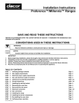
Installing the Anti-Tip Bracket
WARNING:
This appliance requires an antitip device. Before installing
the range, you must locate and
secure the anti-tip bracket to the
floor.
.
When the range is slid into position in the
cutout, the left rear leveling leg slides into
this bracket to prevent the unit from tipping
forward. The bracket location shown here
wilt position the rear edge of the range
top frame flush to the rear walt. From this
position, the bracket allows for up to 5/8"
(16mm) of forward movement of the range.
il ?
i
1) To remove door, rotate catch up
2) Lift door up to 30 ° angle, then
pull door away from the oven
Removing the Oven Door
\
Remove the Kick Panel
Remove the screw at each top corner of
the kick panel. Lift up slightly on the panel
and pull forward to remove.
I
I
4-4-
--*- 1 1/2"(38mm)
:ront face
of cabinet
9 7/16"
(494mm)
-- --
I
-
I
I
2 3/16"--_
(56mm)
I- 11 3/8""_
(289mm) _
Top View - Location of Anti-Tip Bracket
Based on 24" Cabinet Depth
5
_aCD_
4.
All of these range models
must be connected to a
grounded, metallic, permanent
wiring system. Alternatively, a
grounding conductor should
be connected to the grounding
terminal or lead on the
appliance.
Do not use an extension cord
with this appliance. Such use
may result in fire, electrical
shock, or other personal
injury.
Do not install a fuse in the
neutral or ground circuit. A
fuse in the neutral or ground
circuit may result in an
electrical shock hazard.
Do not ground the appliance
to a gas supply pipe or hot
water pipe.
A grounded cold water pipe
must have metal continuity to
electrical ground and must not
be interrupted by insulating
materials. Any insulating
materials must be jumped
with a length of No. 4 copper
wire securely clamped to bare
metal at both ends.
Connection Instructions: This appliance
must be electrically grounded.
With the range positioned directly in front
of the cabinet cutout, feed the appliance
conduit into the electrical junction box.
Then, depending upon local codes, utilize
one of the techniques on the facing page
to connect the appliance to the electrical
power supply.
Option 1 - Connecting to a Four-Wire
Electrical System. (Recommended)
1.
2.
3.
4.
5.
Separate the green and white
appliance wires.
Connect the white appliance wire to
the neutral (white) supply wire in the
junction box.
Connect the black appliance wire to
the black (L1) power supply wire in the
junction box.
Connect the red appliance wire to
the red (L2) power supply wire in the
junction box.
Connect the green appliance wire to
the green house grounding wire in the
junction box.
Option 2 - Connecting the Green
Appliance Wire to the Neutral (White)
Supply Wire - Where Local Codes
Permit)
[_
2.
3.
1.
2.
3.
4.
5.
6.
WARNING:
**Do not connect the green
appliance wire to the neutral
(white) supply wire unless local
building codes permit.
1.
Option 3 - Connecting the Green
Appliance Wire to a Grounded Supply
Wire or a Grounded Cold Water Pipe Where Local Codes Permit
7.
Connect the green and white
appliance wires to the neutral (white)
supply wire in the junction box.
Connect the black appliance wire to
the black (L1) power supply wire in the
junction box.
Connect the red appliance wire to
the red (L2) power supply wire in the
junction box.
Separate the green and white
appliance wires.
Connect the white appliance wire to
the neutral (white) supply wire in the
junction box.
Connect the black appliance wire to
the black (L1) power supply wire in the
junction box.
Connect the red appliance wire to
the red (L2) power supply wire in the
junction box.
Connect the green appliance wire to
a grounded supply wire in the junction
box or to a grounded cold water pipe.
If connecting to a grounded cold water
pipe, a separate copper grounding
wire (No. 10 minimum) must be
connected to a grounded cold water
pipe by means of a clamp and then
to an external grounding connector
screw.
Agrounded cold water pipe must
have metal continuity to electrical
ground and must not be interrupted
by insulating materials. Any insulating
materials must be jumped with a
length of No. 4 copper wire securely
clamped to bare metal at both ends.
Cable from
power supply
Junction
box
RED
WHITE
Wire nut
(4 places)
Conduit from
appliance
Option 1 - Connecting the appliance
to a four-wire power supply
Cable from
power supply
Junction
box
GREEN
RED
Wire nut
(3 places)
Conduit frorr
appliance
Option 2 - Connecting the appliance
a three-wire power supply**
Cable from
power supply
Separate No. 10 (minimum)
",_
Junction
_OX
R,,_"_ED
to
copper grounding wire
No. 4
copper wire _
_
I
WHITE-
Wire nut
Metal
water pipe
Bare metal
(4 places)
Conduit from
appliance
Option
Clamps
3 - Connecting the appliance ground to a grounded
junction box wire or grounded cold water pipe
da=::ar.
6
Installing the Range
Verify Proper Operation
Measure from the floor to the countertop
and adjust the leveling legs as required
to position the top frame at the desired
height, based on the cabinet and
countertop installation. Carefully slide the
range into position in the cutout. The left
rear leveling leg should engage the anti-tip
bracket.
NOTE:
Prior to operating the cooktop or
oven sections of the range, please
read the accompanying
use and
care manual carefully. Important
safety, service and warranty
information is contained within
this manual.
When the range is to be installed as a
"slide-in, self rimming" (with the range
top overhanging the countertop cutout),
measure from the floor to the countertop.
Adjust the leveling legs to position the
bottom edge of the range top frame
approximately 1/8" (13mm) above the level
of the countertop. This wilt allow the range
to slide over the countertop. Carefully slide
the range into position in the cutout. Again,
the teft rear leveling leg should engage
the anti-tip bracket. To lower the range
onto the countertop, turn the leveling legs
counterclockwise. Lower the range until
the bottom of the range top just contacts
the countertop. Do not allow the full weight
of the range to hang on the counter.
Re-installing the Oven Door
Grasp the oven door on opposite sides
and lift it until the door hinges are aligned
with the openings in the oven frame.
Holding the door at about a 30 ° angle from
the horizontal, slide the hinges into the
openings until the bottom hinge arms drop
fully into the hinge receptacles. Lower the
door to the fully opened position, and then
rotate the two hinge catches toward the
oven. Open and close the door completely
to ensure that it is properly installed.
Peel off the protective layer of plastic that
covers the door panel.
When the unit is powered on for
the first time, the cooktop control
will go through a self-check
routine. When the self-check is
complete, the cooktop control will
go into SECURE mode. See the
use and care manual for secure
mode instructions.
To turn on the power supply to the range.
Set the time of day by pressing the
"CLOCK" key and then pressing either of
the "TIME.TEMP" keys ("+" or "-" keys) to
advance or reduce the time in the display
in the desired setting.
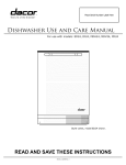
Turn an element, tap the "ON/OFF" key
then tap the slew up/down area of the
desired element. The element witt come
on at a setting of the number touched and
may be adjusted up or down by slewing
up or down on the appropriate key area
with your finger. To activate the Dual
Outer Element, tap the circle key at the
end of the stew area (second row), then
tap or stew your finger up or down on the
second row of numbers. The outer ring
element wilt come on at a setting of the
number touched last. To turn the element
off, tap the "ON/OFF" key. You may turn
off alt active elements at the same time by
tapping twice on the "CANCEL,SECURE"
key located below the controls.
I
1 z 3 4 5 6 7 8 9 10 SI/S
ON/OFF
00
oo
I. I
z 3 4 5 6 7 8 9 10 II$1
ON/OFF
©©
O0
I. 1 z 3 4
O
5 6 7 8 9 1o IISS
{"
5
ON/OFF
oo
OO
1
Z
3
4
6
7
8
9
10
II/I
ON/OFF
"SLEW UP/DOWN"
Element Control
Within 5 seconds, the element should be
fully energized and glowing red. Verify
that the residual heat indicator light comes
on in conjunction with the proper element
within approximately 30 seconds.
_aCD_
.
.
3.
NOTE:
QO
O0
If either the oven or cooktop does
not operate properly, follow these
troubleshooting
steps:
.
Verify that power is supplied
to the range.
Check the electrical
connections to ensure that
the installation has been
completed correctly.
Repeat the above tests.
If the appliance still does
not work, contact Dacor
Distinctive Service at (877)
337-3226. Do not attempt to
repair the appliance yourself.
Have the model and serial
numbers available when you
call. See page 1 for location.
Dacor is not responsible for
the cost of correcting problems
caused by a faulty installation.
NOTES
dacar
8
NOTES
9
=::_acar
All specifications
subject to change without notice. Dacor assumes no liability for changes to specifications.
The Life of the Kitchen2
®
Family Owned
American Made
Dacor = 600 Anton Blvd. Suite 1000 Costa Mesa, CA 92626 = Phone: (800) 793-0093 = Fax: (626) 403-3130 = www.Dacor.com