1
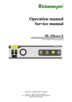
Operation manual Service manual VETLux 150 150 Watt Halogen light source with connector and air pump for flexible endoscopy P O W ER I N TE N SI TY I O - Eickemeyer - Medizintechnik für Tierärzte Eltastr. 8 - 78532 Tuttlingen, GERMANY Tel. +49 (0) 7461 / 96580-0 Fax: +49 (0) 7461 / 96580-90 Internet: www.eickemeyer.de Page 2 of 20 Operation manual VETLux 150 This manual contains information protected by copyright laws. All rights reserved. Manual may not be copied or duplicated, in its entirety or in part. We reserve the right to make technical changes on device prior notice. Copyright Eickemeyer 10.2005 SERVICE ADDRESS: Eickemeyer Medizintechnik für Tierärzte Eltastr. 8 D-78532 Tuttlingen GERMANY Telephone: +49 (0) 7461 / 96 580-0 Fax: +49 (0) 7461 / 96 580-90 BA-E-VETLux150-Eickemeyer 08-03-2006.doc Rev 3.0 Operation manual VETLux 150 Page 3 of 20 Table of contents GENERAL ADVISES........................................................................................................................................... 4 DATA OF THE EQUIPMENT .................................................................................................................................... 4 RIGHTS ................................................................................................................................................................ 4 WARRANTY ......................................................................................................................................................... 4 SERVICE, REPAIRS AND MODIFICATIONS ............................................................................................................. 5 LIABILITY ............................................................................................................................................................ 5 DISPOSAL ............................................................................................................................................................. 5 SAFETY REFERENCE / PLACE THE EQUIPMENT .................................................................................... 6 NORMAL USE ....................................................................................................................................................... 6 USER QUALIFICATION .......................................................................................................................................... 6 UNPACKING / ITEMS INCLUDED ............................................................................................................................ 6 SAFETY PRECAUTIONS OF INSTALLATION............................................................................................................. 6 STORAGE AND OPERATION CONDITIONS ............................................................................................................... 6 SIGNS & SYMBOLS............................................................................................................................................ 7 SYMBOLS ............................................................................................................................................................. 7 SIGNS ................................................................................................................................................................... 7 DESCRIPTION OF THE EQUIPMENT ........................................................................................................... 8 OPERATING ELEMENTS ................................................................................................................................. 9 FRONTPANEL ....................................................................................................................................................... 9 REAR PANEL ........................................................................................................................................................ 9 CONNECTING AND OPERATING ................................................................................................................ 11 CONNECTING THE EQUIPMENT ........................................................................................................................... 11 OPERATING THE EQUIPMENT .............................................................................................................................. 12 SERVICE MANUAL.......................................................................................................................................... 13 GENERAL MAINTENANCE AND REPAIR ADVICE .................................................................................................. 13 SERVICE INTERVALS .......................................................................................................................................... 13 EXCHANGE OF THE MAINS FUSES ....................................................................................................................... 13 EXCHANGE OF LAMP .......................................................................................................................................... 14 CLEANING / DISINFECTING................................................................................................................................. 14 WIRING DIAGRAM.......................................................................................................................................... 15 TECHNICAL DATA .......................................................................................................................................... 16 SPARE PARTS ..................................................................................................................................................... 16 TABLE ‘TECHNICAL SERVICE-INFORMATION’.................................................................................... 17 APPENDIX.......................................................................................................................................................... 18 ELECTROMAGNETIC COMPATIBILITY (EMC) ..................................................................................................... 18 Rev 3.0 BA-E-VETLux150-Eickemeyer 08-03-2006.doc Page 4 of 20 Operation manual VETLux 150 General advises Like all of our other products, this product is the result of years of experience and great care in engineering and manufacture. This manual is destined to learn you understanding the function and the operation of your equipment. Before you switch on the equipment for the first time, please thoroughly read this manual and pay special attention to all safety instructions, so that endangering for the user and the patient is precluded. Please always store this manual with the equipment. Before use, read this manual thoroughly. An insufficient understanding of the dangers, warnings, cautions, and informations in this manual can result in death, serious injury, or equipment damage. This product complies with the requirements of Directive 93/42/EEC concerning medical devices. Data of the equipment The type label (rear of unit) contains technical data, type and serial number of your unit. Please always indicate these data when ordering spare parts or in case of any question. Please enter here the technical data of your device! • Serial No.: ______________________________ • Type: ______________________________ • Date: ______________________________ • Class: ______________________________ • Hz: ______________________________ • Amp.: ______________________________ • Volt: ______________________________ Rights All rights on this user manual, especially the rights of duplication and publication and the rights on translation are reserved. No part of this user manual may be reproduced by any means (by photostatic copy, microfilm or other methods) without preceding written consent of the manufacturer or be reproduced, multiplied or published by means of electronic data processing. The information given in this user manual can be changed or extended without notice and do not represent any liability. Errors and technical changes excepted. Warranty 1 year according to our warranty conditions. Opening the equipment or performance of any repairs or modifications of the equipment by unauthorised persons shall relive the manufacturer of any liability for its performance. Any such opening, repair or modification performed during the warranty period shall void all warranty. Wear parts are not included in the warranty. The firm of the manufacturer shall be liable for failure or deterioration in the safe operation, operational reliability and performance of this equipment only subject to the conditions, that all assembly operations, system expansions, readjustments or repairs to same have been performed by a person or persons duly authorised by the manufacturer, that all electrical installations at the location of us meet applicable national and local electrical codes and that the instrument has been used in accordance with its operating instructions at all times. BA-E-VETLux150-Eickemeyer 08-03-2006.doc Rev 3.0 Operation manual VETLux 150 Page 5 of 20 Service, Repairs and Modifications In conformity with the international safety regulations valid for medical devices, all activities such as check ups, repairs, modifications, calibrations etc. may only be carried out by the manufacturer or by explicitly authorized personnel. All services carried out must be entered in the „Technical Service Notes“ at the back of the user manual. Liability As manufacturer of the device, we only consider ourselves liable for safety, reliability and performance of the unit, if • assembly, re-adjustment, modifications or repairs are performed by persons authorised by us • the electric installation of the respective room corresponds to the regulations of VDE 0107 the instructions found in the user manual are strictly observed when operating the unit. Disposal In accordance with European Directive 2002/96/EC on Waste Electrical and Electronic Equipment, this symbol indicates that the product must not be disposed of as unsorted municipal waste, but should be collected separately. Refer to your distributor resp. the manufacturer for return and/or collection system available in your country. Rev 3.0 BA-E-VETLux150-Eickemeyer 08-03-2006.doc Page 6 of 20 Operation manual VETLux 150 Safety reference / Place the equipment Normal use The equipment may only be used with accessories, wearing parts and disposable items, which have been designated by the manufacturer suitable for the instrument or the safety use of which is proven. User qualification The equipment may only be used by persons, who have a corresponding specialised qualification and who have been instructed in use of the equipment. It is the user’s responsibility to make sure, the equipment is safe and operates properly before using the equipment. Unpacking / items included Carefully unpack the equipment and accessories and remove it from their packing. Check for missing items and evidence of shipping damage. File any complaints with the manufacture or supplier immediately. Retain the original packing materials for later use. These can come in handy, when the equipment must be transported. Please verify immediately after having unpacked the equipment, whether the delivery is complete. The standard extent of delivery includes of the following: S Control unit Power supply cord Manual Safety precautions of installation Always place the equipment on a solid base. The equipment may be used only in rooms having electrical installations conforming to applicable national, state and local electronical codes. The unit must be joined to the central potential equalisation of the operating theatre or of the equipment trolley by means of a grounding cable. The device must be connect to line voltage using the delivered protectively earthed power supply cord. Storage and operation conditions Storage temperature: Operation temperature: -20°C to +60°C +10°C to +40°C rel. humidity: storage: 10% to 90% operation: 30% to 75% Air pressure: storage: 600 mbar to 1300 mbar operation: 700 mbar to 1060 mbar BA-E-VETLux150-Eickemeyer 08-03-2006.doc Rev 3.0 Operation manual VETLux 150 Page 7 of 20 Signs & symbols Symbols Attention, important note! Safety note Service Signs Please read the enclosed instructions ! Unit model BF Beware of dangerous electrical voltage ! Connection for ground potential Alternating voltage ~ Rev 3.0 BA-E-VETLux150-Eickemeyer 08-03-2006.doc Page 8 of 20 Operation manual VETLux 150 Description of the equipment The HL 150 is a powerful 150W-Halogen lightsource for all applications with fibre-optic illumination. The lightintensity makes the lightsource usable for almost all endoscopic disciplin. The output intensity can be easily controlled via control knob without influence on the quality of light. The built in soft-start-electronic protects the lamp against high currents in the switch on/off moments and extends the lamp-lifetime. The lightsource comes equipped with a built-in insuflation pump for use with gastroscopes and other flexible endoscopes. The pump can be switched on/off on the frontpanel. There are adapters available for gastroscopes made by either Olympus, Fujinon or Pentax. The pump can be separately switched on and off. The equipment is desinged by the latest standards of security for medical equipment and complies with the demands of CE. BA-E-VETLux150-Eickemeyer 08-03-2006.doc Rev 3.0 Operation manual VETLux 150 Page 9 of 20 Operating elements Frontpanel P O WER I N TE N SI TY I O - 3 4 (1) (2) (3) (4) 1 2 Mains switch Switch Air pump Intensity adjustment Light guide connector Rear panel D - 2 54 many ACHT UNG! Vor dem Öffnen des Ger ätes Netzs tecker ziehen! CAU TION! Before open thedevice pull out the mains plug! 4 (5) (6) (7) 5 6 Connector potential ground Line connector Fuse holder Rev 3.0 BA-E-VETLux150-Eickemeyer 08-03-2006.doc Page 10 of 20 Operation manual VETLux 150 Mains switch The control unit is turned on by switching the mains switch. The mains switch has two different switching positions: I switched on O switched off When the control unit is switched on, this is indicated by the up-light green lamp inside the switch. Intensity control knob Use this knob to control the output intensity. Turning the knob to the left decreases intensity, turning to the right increases intensity. Pump switch The integrated pump is switched on and off by using the corresponding switch. Switch on the pump only right before the use of it and switch it off right after. The pump is maintenance-free. Make sure, no dirt and liquids can get into the adaptor. Connector for fibrescope For lightguide connection, there are interchangeable adapters available for all brands of lightguides. For gastroscopic applications, the lightsource comes equipped with a special adapter with integrated air supply for your gastroscope brand. Using the wrong lightguide or adaptor can damage the lightsource and the accessories and threats the patient. Potential ground connector Basically, the control unit is protectively earthed by the 3-pin power supply cord when it is connect to a protectively earthed wall socket, as prescribed. When running the equipment in rooms which comply to class 1 or 2E according to MedGV, the control unit must be joined to the central potential equalisation of the operating theatre or of the equipment trolley by means of a grounding cable. Fuse holder It contains the mains fuses. You have to control whether your mains voltage corresponds with the selection shown in the window. Line connector The plug of the power supply cord is connect to the mains terminal device. Use only the delivered supply cord. BA-E-VETLux150-Eickemeyer 08-03-2006.doc Rev 3.0 Operation manual VETLux 150 Page 11 of 20 Connecting and operating Connecting the equipment Before you connect the mains plug, check on the back of the equipment that the voltage indicated (in the square panel above the mains socket) is the correct one. voltage = 230VAC indicator ‘230’ voltage = 115VAC indicator ‘115’ If the incorrect voltage is indicated then the equipment may under no circumstances be connect. Before connecting a light cable into a light source adapter of the equipment, please ensure that you have the correct plug and adapter. A plug that is too long or too thin can for example be pushed too far into the equipment, and can damage the sensitive diaphragm or lens inside. This will result moreover in considerable loss of light, in the same way as a plug that is too short, or a plug of the wrong diameter, because of the wrong position of the contacts at the light entry. All connection have to be done before you switch on the unit ! Connect the power supply cord ! Use the delivered protectively earthed power supply cord to connect the control unit to the mains. Make sure that on comes indicated mains voltage is correct. Attach the equipment only to agrounded protective contacz socket. Connect a fibrescope ! Verify, whether the installed adapter matched the fibrescope you want to connect. Plug in the light plug of the fibrescope. Thus the air connection is automatically fixed. Connect the water bottle to the fibrescope (if necessary). There is a holder for the water bottle installed at the left side of the housing. Connect the potential equalisation conductor ! Join the terminal device for potential equalisation on the rearpanel with the central potential equalisation of the operating theatre or of the equipment trolley. Rev 3.0 BA-E-VETLux150-Eickemeyer 08-03-2006.doc Page 12 of 20 Operation manual VETLux 150 Operating the equipment Before connecting a light cable into a light source adapter of the equipment, please ensure that you have the correct plug and adapter. A plug that is too long or too thin can for example be pushed too far into the equipment, and can damage the sensitive diaphragm or lens inside. This will result moreover in considerable loss of light, in the same way as a plug that is too short, or a plug of the wrong diameter, because of the wrong position of the contacts at the light entry. After switching on a light source and the ensuing ignition of the lamp, the equipment should remain switched on for at least ¼ hour. A shorter shining period will considerably shorten the life expectancy of the lamp! After switching off a light source however, it may be immediately switched on again. A waiting period or cooling off period is not necessary. After connecting the mains, the grounding conductor, the light cable and the endoscope, the equipment is ready for use, and can be switched on at the mains switch. The green lamp inside the switch lights up. Now you can begin working with the lightsource. Set the desired intensity by turning the corresponding knob. There are no other control elements available to use during operation. Set the pump to on or off by switching the corresponding switch. Please switch on the pump only when necessary BA-E-VETLux150-Eickemeyer 08-03-2006.doc Rev 3.0 Operation manual VETLux 150 Page 13 of 20 Service manual General maintenance and repair advice The instructions and information given in this chapter are only for instructed personnel, who are aware of the safety precautions necessary for repair and maintenance of medical electronic devices. The manufacturer refuse any liability for unauthorised repair and modification. The manufacturer will provide those circuit diagrams, itemised parts listings, descriptions, sets of adjustment instructions and other items of available documentation to suitably qualified user personnel duly authorised by the manufacturer for their use in repairing those components of the equipment that have been designated by their respective manufactures as reparable. Only the supply of such technical documentation relating to the equipment shall not be construed as constituting manufacturer’s authorisation of user’s personnel, regardless of their levels of technical training, to open or repair the equipment. Explicitly exempted here from are those maintenance and repair operations described in this manual. Service Intervals The equipment should be controlled on save function by authorized service personal at least one time the year. These controls should be done every time too, when a lamp is exchanged. Exchange of the mains fuses The mains fuses are located on the rearpanel of the control unit, right above the mains terminal device in a small drawer. If you need to exchange the mains fuses, proceed as follows: PULL OUT THE MAINS PLUG! Loosen the drawer by unfastening the two clamps located to the left and to the right of the drawer with a peaked tool and pull out the drawer. Take out the fuses. Check the fuses. A blown fuse is indicated by the blackened glass cylinder or the visibly melted fuse conductor. If necessary, check the fuse with an ohmmeter. Install the corresponding fuses. Re-install the fuse-drawer. Switch on the equipment again. If you have exchanged a defective fuse against a new one and the fuse blows again, the unit has an error. In this case, you must return the device to your dealer for testing and repair. Rev 3.0 BA-E-VETLux150-Eickemeyer 08-03-2006.doc Page 14 of 20 Operation manual VETLux 150 Exchange of lamp The only part subject to wastage in the equipment are the lamp. The manufacturer of the lamp estimates the minimum life expectancy as 50 hours. After that, the quoted light wattage reduces drastically and there may be difficulties in igniting. In order to secure safe operation of the equipment, the lamp should be changed after expire of this operation time. The lamp must be changed for a new one as following: - PULL OUT MAINS PLUG! Turn the light source buttom up! Loosen the screw on the buttom and remove the lamp cover. Attention: If the machine has been operating shortly beforehand the lamp could be very hot. All remaining current in the electronics will be, in a few seconds after switching off the equipment, completely safely discharged, so there is no danger in handling the equipment here. Pull out the lamp upwards out of its holder. Hold fast the reflector of the lamp and remove the cable from the lamp. Install the cable now to the new lamp. Insert a new lamp into the holder and push it downwards. CHECK, the little nose of the lamp is in the right pocket. Re-install the cover and tighten it with the screw. Observe the grounding cable! Further servicing, which should be done in conjunction with lamp replacement Dust should be removed from the equipment with a vacuum cleaner using a small nozzle attachment. Dust can sometimes cling quite firmly to the ventilator blades. This should then be cleaned with a cloth and a little alcohol/spirits. Likewise dust settles on the heat protective filter (with lens, optional), this should also be cleaned with a soft cloth or blotting paper and pure alcohol or spirits. Cleaning / Disinfecting NOTE: PULL OUT THE MAINS PLUG! All parts of the outer surfaces of the equipment are totally insensitive to all the usual cleaning and disinfecting materials, so that you can use any of these without limitation. Apply liquids using a soft cloth or soft blotting paper, in order to avoid scratches on the surfaces and in order to be able to control the amount of liquid. With flammable liquids like alcohol especially, you should apply with a cloth. Do not let any liquid get into the equipment. After cleaning with flammable liquids, leave the equipment to dry for one hour, before it is switched on again. There is danger for example that an alcohol-air explosive mixture could form after cleaning. BA-E-VETLux150-Eickemeyer 08-03-2006.doc Rev 3.0 Operation manual VETLux 150 Page 15 of 20 Wiring diagram Rev 3.0 BA-E-VETLux150-Eickemeyer 08-03-2006.doc Page 16 of 20 Operation manual VETLux 150 Technical Data Power supply 230 VAC ± 10% or 115 VAC ± 10% Lamp Halogen reflector lamp, 15V, 150W Power consumption 160 W Fuses 2 fuses 5x20 mm 230 VAC: 1,2,5 A 115VAC: 2,5A Dimensions 245 x 120 x 200 mm ( W x H x D ) Weight 3,5 kg Class / Type 1 / BF Manufactured and tested acc. IEC 601-1 / CE; EN 60601-1; 93/42/EEC Spare parts Lamp Halogen reflector lamp 15 V, 150 W OSRAM HLX 64634, EFR Mains fuses: fine fuses, 5x20mm, delay acting for 230VAC: 1,25A for 115 VAC: 2,5mA BA-E-VETLux150-Eickemeyer 08-03-2006.doc Rev 3.0 Operation manual VETLux 150 Page 17 of 20 Table ‘Technical service-information’ Date Check Rev 3.0 Signature BA-E-VETLux150-Eickemeyer 08-03-2006.doc Page 18 of 20 Operation manual VETLux 150 Appendix Electromagnetic Compatibility (EMC) Precautionary measures Electromedical devices are subject to special precautionary measures concerning electromagnetic compatibility (EMC). This device is to be used for the purposes described in the operation manual and has to be installed, set up, and operated in compliance with the EMC guidelines. Impact of mobile and portable RF communication devices The emission of high frequency by mobile communication devices may impact the function of the electromedical device. Operating such mobile communication devices (e.g. cell phones, GSM phones) in the proximity of the electromedical device is prohibited. Electrical connections Connections between such plugs and sockets may not be established without first implementing ESD precautionary measures. ESD precautionary measures The following are ESD precautionary measures: - Connect all electrical equipment to be connected to the device to a potential equalisation system (via PE). - Use only the equipment and accessories mentioned in the operation manual. The staff have to be informed about and trained in ESD precautionary measures. The VETLUX 150 should be operate in an enviroment as stadet below. The user have to make sure that the VETLUX 150 will be operate in such enviroment. Manufacturer declaration – Electromagnetic application Noise emmission measurement Correspondence Electromagnetic enviroment - Guide Group 1 The VETLUX 150 used HF-energy solely for internal functions. Therefore, the HF-emission is very low and interferences with adjacent electronical equipment are improbable. HF- Emission acc. to CISPR 11 HF- Emission acc. to CISPR Class B Harmonics acc. to IEC 61000-3-2 Class A Voltage fluctuations / Flicker acc. to IEC 61000-3-2 unapplicable The VETLUX 150 is adapted for use in all facilities including living areas and such facilities with public utility provider. Manufacturer declaration – Electromagnetic noise immunity Noise immunity tests IEC 60601 – test level Correspondence level Electrostatic discharge (ESD) acc. to IEC 61000-4-2 ± 6 kV contact discharge ± 6 kV contact discharge ± 8 kV air discharge ± 8 kV air discharge Quick transient ± 2 kV electrical disturbances / for mains lines Bursts acc. to 61000-4-4 ± 1 kV for Input and output lines BA-E-VETLux150-Eickemeyer 08-03-2006.doc ± 2 kV for mains lines ± 1 kV for Input and output lines Rev 3.0 Electromagnetic enviroment Guide Floors should be consist of concrete or wood or furnished with ceramic tiles. If the floor furnished with synthetic material, the relative air humidity should be 30 % average. The quality of mains voltage should be comply typical mains voltage of business or hospital enviroment. Operation manual VETLux 150 Surge voltage acc. to IEC 61000-4-5 Acc. to IEC 61000-4-11 Magnetic field by supply frequency (50 / 60 Hz) acc. to IEC 61000-4-8 Page 19 of 20 ± 1 kV push-pull voltage ± 1 kV push-pull voltage ± 2 kV push-push voltage ± 2 kV push-push voltage < 5% UT (> 95% UT collaps)for ½ period < 5% UT (> 95% UT collaps)for ½ period < 40% UT (> 60% UT collaps)for 5 periods < 40% UT (> 60% UT collaps)for 5 periods < 70% UT (> 30% UT collaps)for 25 periods < 70% UT (> 30% UT collaps)for 25 periods < 5% UT (> 95% UT collaps)for 5 sec. < 5% UT (> 95% UT collaps)for 5 sec. 3A/m 3A/m The quality of mains voltage should be comply typical mains voltage of business or hospital enviroment. The quality of mains voltage should be comply typical mains voltage of business or hospital enviroment. If the user of the VETLUX 150 demand continued functions also by appearance of interrupts, it will be recommended to operate the VETLUX 150 by non-interruptable power supply. Magnetic fields by line frequency should be correspond to typical values you will find in business and hospital enviroments. Note: UT is the line AC voltage before using the test level. Manufacturer declaration – Electromagnetic noise immunity Noise immunity test IEC 60601 – test level Correspondence level Electromagnetic enviroment - Guide Portable and mobile radio transmitter should not be use within the recommended safety distance to the VETLUX 150 (including the lines)! The recommended safety distance will be calculate by the appropriate transmitting frequency formula. Recommended safety distance: Guided HF-disturbances acc. to IEC 61000-4-3 3 Veff 150 KHz to 80 KHz 3 Veff d=1,2 √P Radiated HF-disturbances acc. to IEC 61000-4-3 3V/m 80 MHz to 2,5 GHz 3V/m d=1,2 √P 80 MHz to 2,5 GHz d=2,3 √P 80 MHz to 2,5 GHz P – transmitter wattage rating (W) acc. to manufacturer (transmitter)data d – recommended safety disdance in meters (m) The electrical field strength of fixed radio transmitter is lower than the correspondence levelb according to a Rev 3.0 BA-E-VETLux150-Eickemeyer 08-03-2006.doc Page 20 of 20 Operation manual VETLux 150 fieldworka. In the enviroment of equipment which bore the following pictograph, it is possible to appear interferences. Note 1: At 80 MHz and at 800 MHz the higher result is valid. Note 2: This guideline may not be the case for all situations. The spread of electromagnetic waves will be affect by absorption and reflexion of buildings, objects and humans. a b The electric field strength of fixed transmitter, like wireless telephones, mobile radio services, AM- and FM broadcast transmitter and TV transmitter, couldn’t be predetermine correctly. In order to ascertain the electromagnetic enviroment at fixed HF-transmitter, it is commendable to inspect the location. If the ascertained field strength at the VETLUX 150 location exceed the specified correspondence level, it’s may be necessary to adopt other means, e.g. reorientation or removal the VETLUX 150. By means of the frequency range from 150 kHz to 80 MHz the field strength is less than 3 V/m Commendable safety distances between portable and mobile communication appliances and the VETLUX 150 The VETLUX 150 is intendet for operation in electromagnetic enviroments, where radiated HF-disturbances will be controlled. The customer resp. the user of the VETLUX 150 can help to prevent electromagnetic disturbances by compliance minimum distances between portable and mobile HF communication appliances (transmitter) and the VETLUX 150. Commendable safety distances acc. to the maximum power output of the communication appliance: Safety distance acc. to transmitting frequency (m) Wattage rating of the transmitter (W) 150 kHz to 80 MHz 80 MHz to 800 MHz d=1,2 √P d=1,2 √P d=2,3 √P 0,01 0,12 0,12 0,23 0,1 0,38 0,38 0,73 1 1,2 1,2 2,3 10 3,8 3,8 7,3 100 12 12 23 BA-E-VETLux150-Eickemeyer 08-03-2006.doc Rev 3.0 800 MHz to 2,5 GHz Operation manual VETLux 150 Page 21 of 20 For transmitter, whose wattage rating isn’t stated above, the safety distance can be calculated by using the equations in the respective column. P is the wattage rating of the transmitter acc. to the specifications of the transmitter manufacturer. Note 1: To calculate the commended safety distance of transmitter, with a frequency range from 80 MHz to 2,5 GHz, was an additional coefficient of 10/3 used. The additional coefficient should reduce the probability of disturbances by portable / mobile communication appliance, which are unintentional brought in the patient range. Note 2: This guideline may not be the case for all situations. The spread of electromagnetic waves will be affect by absorption and reflexion of buildings, objects and humans. Rev 3.0 BA-E-VETLux150-Eickemeyer 08-03-2006.doc