1
INSTALLATION
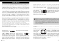
Home cinema systems can be built with different levels of complexity. This decoder preamplifier is the central control of your system. Components of your AV-system, which you wish to playback through the SAVC2, are variously called “sources”, “signal sources” or “unit sources” in the following pages. These include CD-players, DVD-players, tuners, cassette players, DAT-recorders, personal computers, record-players,
portable audio systems and many more. “AV-sources” are components of your system, which play back
video signals as well as audio signals. If a variety of units is to be connected, it is more difficult to give
an overview of the full system. Therefore imagine your home cinema system to be a general system, which
receives input signals by means of different cables and transmits output signals.
In doing so, this preamplifier assumes the following tasks: commutation of audio and video signals from
various sources to be played back, preparation of different input signals, decoding digital signals, system
volume control, control of the treble and bass of sounds, adaptation of the sound to different speaker configurations by channel management and switching between different stereo, DSP and surround playback
modes. To make this possible, the SAV-C2 must be properly installed and configured so that the
audio/video signals from different media (CD, DVD, TV, Tuner) can be fed into the system via the SAV-C1
inputs, be processed there and output to power amplifier(s) and video display.
Here it is already clear that you can also feed the video signal directly of the AV-source to the video display directly and not through the preamplifier. This may make sense, for example, if you only have one
source unit, the video signals from which you want to see, while the preamplifier processes the associated sound (in this case you exclude any, even minimal, loss of quality by passing the video signal through
the preamplifier). Or even if one of the source units outputs a video format not supported by the SAV-C2
(VGA, DVI, etc.). The advantage of using the video signal path through the preamplifier lies in also being
able to switch over the video signals of the AV-sources by selecting the input on the SAV-C2.
First connect the cables for all input connections, then for all output connections of the preamplifier. Lastly
connect the power cable to the unit and plug it into a socket. There are different standards for audio and
video connections of the SAV-C2.
The three possible video signal connections, which can be selected to connect AV sources and the video
display, will be described in the following paragraphs.
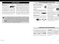
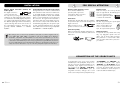
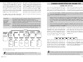
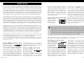
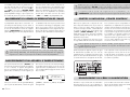
“VIDEO” connection: Composite Video signal
This signal connection is
supported by the majority
of AV components.
The corresponding terminal socket is often labelled
“VIDEO” or “COMPOSITE” and marked yellow
like the plug. The signal is always in Interlaced
Scan mode, Progressive Scan is impossible. You
need a 75Ω signal cable with RCA plugs for this
connection. The picture quality achieved depends
greatly on the quality of the composite cable used.
Of all the possible video connections used, this one
offers the lowest picture quality. It should only be
50
Vincent
used if the AV source or the video display (e.g. TV,
projector) supports none of the other formats.
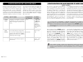
“S-VIDEO” connection: S-Video signal
Most home-cinema components support this type
of signal. The associated
connector is often labelled “S-VIDEO” or “Y/C”.
The S-Video signal is always in Interlaced Scan
mode, Progressive Scan is impossible. You need a
special S-Video cable with Mini DIN plugs for this
connection. The picture quality achieved depends
on the quality of the cable used. The signal stanS-VIDEO
dard offers greater picture quality than the
Composite Signal, but is superseded by the
Component Signal. Therefore it should be used if
the AV source or the video display (e.g. TV, projector) does not support the “Component” standard.
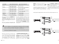
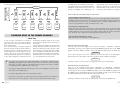
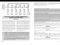
“YPbPr“ Connection: Component Video Signal
This connection is often
Y
found on higher-grade
AV components. The three Pb
connector sockets of this
Pr
signal standard are often
labelled “YPbPr” or “COMPONENT” and colourmarked (red, green, blue). Dependent on the abili-
ties of the AV source and the video display, the
Component Signal may be present in Interlaced
Scan or Progressive Scan mode. Basically, you
need three 75Ω RCA cables for this connection.
However a cable suitable for the Component
Signal should be used, which combines all three
lines in a cord and has three RCA plugs on each
end coloured red, green and blue. This standard
offers the highest picture quality and should be
used if the source and the video display (e.g. TV,
projector) support this format.
Only one of the three video connection standards needs to be used. Which one is selected,
depends on the availability of input sockets on your video display and this preamplifier.
Only two of the selectable inputs on the SAV-C1 offer S-Video and Component connections!
Note that there is no conversion between the three different picture formats (S-Video,
Component and Composite), therefore a video display (TV, projector) will only receive video
signals from AV sources which use the same type of connection as the video display itself.
You are, however, free to feed the video signal from AV sources that have a different video standard direct to the display unit.
For connection of the audio signals from the source units, one analogue and two digital standards are
used at the unit.
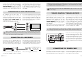
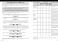
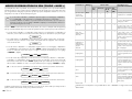
Analogue sound via RCA connections (stereo or multi-channel)
This signal connection is
used by almost all hi-fi
or AV components.
One analogue sound
signal can be transferred
per plug connection; this
is associated with one speaker channel (right, left,
centre, etc.). Coaxial cables with RCA plugs and
sockets (RCA) are coming into use. Some sources
with digitally stored or digitally received sound
(DVD, SACD, TV-receiver, etc,) and most AV receivers and preamplifiers have the multi-channel ana-
logue sound connection. In the case of stereo transmission, the corresponding connector sockets are
generally labelled “LINE IN/OUT”, “2-CHANNEL
IN/OUT”, or “AUDIO IN/OUT”. Multichannel
connector sockets generally carry the designation
“6.1 CHANNEL”, “ANALOG INPUT” or a similar
label. Connector sockets and plugs for the right
channel are marked red, those for the left channel
white. These connections are not designed for
digital audio transfer and therefore also not for
DTS or Dolby Digital formats. The quality of the
sound transmitted depends on the quality of the
cable used.
Vincent
51