1
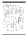
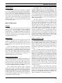
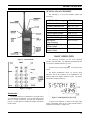
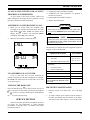
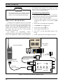
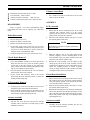
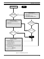
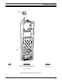
Maintenance Manual EDACS IPE SERIES 800 MHz Duplex Portable Radio E AE/LZB 119 1890 R1A MANUAL REVISION HISTORY Revision R1A Date 01/97 Reason For Change Original NOTE Repairs to this equipment should be made only by an authorized service technician or facility designated by the supplier. Any repairs, alterations or substitution of recommended parts made by the user to this equipment not approved by the manufacturer could void the user’s authority to operate the equipment in addition to the manufacturer’s warranty. NOTICE! The software contained in this device is copyrighted by Ericsson Inc. Unpublished rights are reserved under the copyright laws of the United States. This manual is published by Ericsson Inc., without any warranty. Improvements and changes to this manual necessitated by typographical errors, inaccuracies of current information, or improvements to programs and/or equipment, may be made by Ericsson Inc., at any time and without notice. Such changes will be incorporated into new editions of this manual. No part of this manual may be reproduced or transmitted in any form or by any means, electronic or mechanical, including photocopying and recording, for any purpose, without the express written permission of Ericsson Inc. Copyright January 1997, Ericsson Inc. 2 AE/LZB 119 1890 R1A TABLE OF CONTENTS PAGE SPECIFICATIONS........................................................................................................................................................................................... 4 DESCRIPTION ................................................................................................................................................................................................ 6 RELATED MANUALS ............................................................................................................................................................................... 6 RADIO FEATURES .................................................................................................................................................................................... 6 USER PROGRAMMABLE FEATURES .................................................................................................................................................... 6 PC PROGRAMMABLE FEATURES.......................................................................................................................................................... 6 CIRCUIT DESCRIPTION................................................................................................................................................................................ 6 TRANSMITTER BLOCK............................................................................................................................................................................ 8 Transmit Frequency Generation............................................................................................................................................................... 8 Transmit Offset Synthesizer..................................................................................................................................................................... 8 Transmit Driver Amplifier ....................................................................................................................................................................... 8 Transmit Bandpass Filter (Z361) ............................................................................................................................................................. 8 Power Amplifier (N305) .......................................................................................................................................................................... 8 DC-DC converter ..................................................................................................................................................................................... 8 Duplexer .................................................................................................................................................................................................. 8 Power Detection....................................................................................................................................................................................... 8 PowerControl........................................................................................................................................................................................... 9 RECEIVER BLOCK.................................................................................................................................................................................... 9 General..................................................................................................................................................................................................... 9 DuplexFilter ............................................................................................................................................................................................. 9 Front End Chip (N211)............................................................................................................................................................................ 9 Buffer and IF/AF chip.............................................................................................................................................................................. 9 RSSI....................................................................................................................................................................................................... 10 RSSI Range............................................................................................................................................................................................ 10 CONTROLS AND INDICATORS............................................................................................................................................................. 10 Display ................................................................................................................................................................................................... 10 Illumination............................................................................................................................................................................................ 11 OPTIONS AND ACCESSORIES .............................................................................................................................................................. 11 PLACING AN INTERCONNECT CALL (IPE-200)................................................................................................................................. 12 Volume Control ..................................................................................................................................................................................... 12 Mute Key ............................................................................................................................................................................................... 12 LAST NUMBER RE-DIAL ....................................................................................................................................................................... 12 A CALL IS UNSUCCESSFUL OR A CALL IN PROGRESS IS INTERRUPTED.................................................................................. 13 ANSWERING AN INTERCONNECT CALL ........................................................................................................................................... 13 UNANSWERED CALL COUNTER ......................................................................................................................................................... 13 TURNING THE RADIO OFF.................................................................................................................................................................... 13 PREVENTIVE MAINTENANCE ............................................................................................................................................................. 13 PERSONALITY PROGRAMMING.......................................................................................................................................................... 14 Personality Programming Mode ............................................................................................................................................................ 14 FLASH PROGRAMMING ........................................................................................................................................................................ 15 TEK Box And Utility Software.............................................................................................................................................................. 15 TROUBLESHOOTING ............................................................................................................................................................................. 16 DISASSEMBLY ........................................................................................................................................................................................ 17 Radio Disassembly................................................................................................................................................................................. 17 Circuit Board Removal .......................................................................................................................................................................... 17 LCD Assembly Removal........................................................................................................................................................................ 17 Antenna Assembly ................................................................................................................................................................................. 17 Volume Control Knob ........................................................................................................................................................................... 17 ASSEMBLY............................................................................................................................................................................................... 17 LCD Assseesbly ..................................................................................................................................................................................... 17 Circuit Board Installation....................................................................................................................................................................... 17 Antenna Assembly ................................................................................................................................................................................. 17 Radio Assembly ..................................................................................................................................................................................... 18 Volume Control Knob ........................................................................................................................................................................... 18 3 AE/LZB 119 1890 R1A SPECIFICATIONS GENERAL FCC Identification Number AXATR-352-A2 DOC Type Number 287 159 165A Model: IPE-100 (NON-DTMF) IPE-200 (DTMF) KRD 103 124/1 KRD 103 124/2 Dimensions (H x W x D): 5.1” x 2.1” x 1.7” (130 x 52 x 42 mm) Weight: 12 oz (with High capacity battery) Battery Life: Extra high capacity battery 16 Hrs. High capacity battery 10 Hrs. Maximum Capacity: EDACS Systems/Groups 64 Operating Voltage: 6.5 V (Nominal) Operating Temperature Range: -22°F to + 140°F (-30°C to +60°C) ENVIRONMENTAL STANDARD U.S. MIL-STD 810E Methods/Procedures * Low Pressure 500.3/1,2 High Temperature 501.3/1,2 Low Temperature 502.3/1,2 Temperatue Shock 503.3/1 Solar Radiation 505.3/2 Blowing Rain 506.3/1 Humidity 507.3/2 (Cycle 5) Salt Fog 509.3/1 Blowing Dust 510.3/1 Vibration 514.4/1 CAT 1, 10 Shock 516.4/1,4 * Also meets equivalent MIL-STD 810 C&D TRANSMITTER (25 kHz Channel) Frequency Range (MHz): 806-825 Rated Output Power (Watts): 1.0 RF Output Impedance (Ohms): 50 Frequency Stability (ppm): 1.5% Conducted and Radiated Spurious (dBc): Per TIA FM Hum and Noise (dB): -39 Audio Response (per EIA 603): max 3% 4 AE/LZB 119 1890 R1A RECEIVER (25 kHz Channel) Frequency Range (MHz): 851-870 RF Input Impedance (Ohms): 50 Sensitivity (uV per EIA 603 12 dB SINAD): -118 dBm Selectivity (dB per EIA 603): -60 Frequency Stability (ppm): 1.5% Intermodulation Rejection (dB): -66 Spurious Rejection (dB): -65 FM Hum and Noise (dB): -41 Audio Response (per EIA 603): <3% Audio Output (Watts): 0.5 5 AE/LZB 119 1890 R1A DESCRIPTION USER PROGRAMMABLE FEATURES The IPE Series radio is a synthesized, microprocessorbased, high performance portable FM radio designed for EDACS systems. The lightweight radio provides reliable communications operation in Enhanced Digital Access Communications System (EDACS) trunking environments. Dispatch features such as group calls, individual calls, agency/fleet calls, etc. are offered. Duplex interconnect is also provided in EDACS trunked environments while operating in the Telephone Interconnect Mode. • Store Telephone Number (name) Stores telephone numbers (names) in memory. • Recall Telephone Number (name) Recalls telephone numbers (names) from memory. • EDACS System Change current EDACS System. • Group Selection Change current EDACS Group. • Electronic Lock/Call restrictions Locks the radio to unauthorized use and personal lock code. The radio is manufactured with advanced state-of-theart technology and designed with a minimum of serviceable parts. It is not practical to service the radio to component level (in the field). Technicians servicing this radio should only be concerned with isolating a problem to software or hardware. Repair is limited to reloading software or replacing the circuit board. There are no alignments or adjustments to be made. This manual provides the instructions for: • Battery Saver Selects amount of battery savings. • Ring Volume Changes ring volume and type. • Ring Tone Selects the ring tone frequency. • LCD contrast Sets LCD display contrast. • Key Burst, Tones, Clicks Selects whether keypad numeric keys (0-9, #, *) produce DTMF tones or key clicks. • Backlight Selector Keypad or display illumination to be automatic or switched off. • Battery Voltage Shows the input battery voltage to the radio, for example, 6-3 = 6.3 volts. • Personality Programming Indicates the radio is in the PC Programming mode. • Resettable Accumulated Call Time Used to display total air time since last reset. • Last Call Time Shows minutes and seconds of last call made. • • • • basic radio operation programming the radio personality and flash code isolating a problem to hardware or software disassembling the radio and replacing the circuit board RELATED MANUALS Operator's Manual.....................................AE/LZT 123 1907 EDACS-2 PC Programming Guide..........................TQ-3373 Portable Handsfree User’s Guide..............AE/LZT 123 1882 RADIO FEATURES The lightweight (12 oz) radio provides cellular-like duplex interconnect with the power and efficiency of EDACS trunking. The radio takes advantage of EDACS Infinity battery technology and provides up to 16 hours of standby on a single charge. The IPE offers all the duplex interconnect features in a cellular telephone including: • full duplex interconnect • familiar telephone - style keypad • 25-number call list • last number redial for fast, effortless use • call length timer • two-line, 10-character alphanumeric display that's backlit for nighttime use 6 restrict accepts PC PROGRAMMABLE FEATURES The radio is PC Programmable, which allows the radio to be customized or upgraded quickly and easily. All PC programmable functions are controlled by the microprocessor and are field programmable using the EDACS-2 PC Programmer and a compatible DOS based PC. The programmable parameters are stored in a EPROM and accessed by the microprocessor as needed. Refer to the EDACS-2 PC Programming manual for detailed programming instructions. CIRCUIT DESCRIPTION The block diagram for the IPE-200 is shown in Figure 1. AE/LZB 119 1890 R1A Figure 1 - Block Diagram 7 AE/LZB 119 1890 R1A TRANSMITTER BLOCK Transmit Frequency Generation The main VCO (G481) has a frequency range from 928.2625 Mhz to 947.237 Mhz. This signal is mixed in the Ruth chip (N431) with the transmit offset frquency of 122.25 Mhz to generate the carrier and side band frequencies. The carrier and upper sideband are suppressed to leave only the desired transmit frequency. For example, the VCO frequency of 937.75 Mhz mixed with the offset frequency of 122.25 Mhz generates a transmit frequency of 860.5 Mhz. Transmit Offset Synthesizer The task of the transmit synthesizer is to supply the power amplifier stage with the transmit signal at the chosen transmitter frequency, 806.0125-824.9875 Mhz, in steps of 12.5 KHz. The reference for the transmit synthesizer comes from an accurate 12.8 Mhz source (N511, 1.5 ppm) which is divided down to 12.5 KHz in the synthesizer chip. The transmit synthesizert creates a fixed 122.25 Mhz signal by phase locking a down-divided VCO signal to the 12.5 Khz reference signal. The local oscillator signal is then mixed with the 122.25 Mhz signal to create the transmit frequency signal. The transmit VCO is located in Ruth (N431) and has a sensitivity of about 3.4 MHz/V. An external tank circuit is located off of pins 9 and 10 and is tuned by a varicap diode (V431). One part of the VCO is sent through a buffer stage into the PLL for phase locking. The main part of the signal is fed to the transmitter mixer in Ruth. The receive signal is then mixed down with the 122.25 Mhz signal to form the transmitter frequency (F_Tx) at about 0 dbm and then fed to the discrete driver stage in the transmitter block. A precharge circuitry is used to keep the loop filter chanrged to approximately 2.5 V in standby in order to get a shorter lock in time. Transmit Driver Amplifier The transmit frquency (F_Tx) is next sent to a variable gain driver amplifier. The transistor used (V302) is a bipolar type in a common emitter configuration with a maximum gain of 14 dB. Gain control is achieved by varying the collector voltage of the RF transistor. A PNP pass element (V3 11) and NPN driver (V3 12) is used for this purpose. This configuration offers unconditional stability and good dynamic range. The output and inputs are matched to 50 ohms. There is an attenuator (R302, R303, and R304) at the input to increase reverse isolation. The amplifier is switched on and off with VTx and the control signal VPAON. 8 Transmit Bandpass Filter (Z361) The transmit frequency leaves the driver stage and is sent through a bandpass filter (Z361) before it is sent to the main power amplifier (N305). The bandpass filter is of the SAW type with 20 dB of rejection out of band and an insertion loss of approximately 2.5 dB. Power Amplifier (N305) The power amplifier is a 2 stage GaAs FET with roughly 30 dB of gain. The gain and thus output power is varied by means of the input drive level. The hybrid module is matched to 50 ohms input and output impedance. Pin I is the RF input, pin 2 is the negative supply (Vgg = -3.5 V) , pin 3 and 4 are the positive supplies (Vddl = Vdd2 =6.5 volts), and pin 5 is the RF output. The power amplifiers can provide at least 32.5 dbm (1.8 W) of output power. The extra power is needed due to the severe losses in the duplexer. DC-DC converter The power amplifier and the display have to be biased with a negative voltage, therefore N33 1 converts VDIG to 3.5 V. It is extremely important that the negative voltage be applied to the PA before the drain voltage is switched on. The circuit is designed to provide the PA with a negative voltage at all times. Duplexer The duplex filter consists of a 3-pole transmit section of low pass characteristic with a notch at the receive frequency and a 4-pole receive section filter all in one package. The task for the transmit filter is to suppress wide band noise evolving from the VCO and the power amplifier on receive frequencies. It is also important to suppress harmonics of the transmitter frequency by 45 dB or more. The filter has at least 36 dB attenuation in the Rx band and 30 dB at the Tx harmonics in order to meet regulatory agency requirements. Power Detection A schottky diode is used to rectify the RF (V3 13). This diode is forward biased to avoid having the diode snap off when detecting low levels of RF. Temperature compensation is achieved by including a second schottky diode in series with the POWLEV voltage on the input of the power control loop. AE/LZB 119 1890 R1A PowerControl The output power from the power amplifier is regulated by an active feedback loop. The reference value POWLEV is set via a DIA converter in Bertram and is connected to the positive input of an op-amp. POWSENSE, the detected output power level, is connected to the negative input of the same op-amp. The op-amp produces an error voltage which controls the base of V3 12. This ultimately varies the collector voltage of V302 which in turn varies the output level of the driver stage. The bandpass filter is needed for spurious response rejection (suppression of the first image frequency). The filter also suppresses the local oscillator backwards. The bandpass filter is a SAW filter with a center frequency of 860.5 MHz and a pass band width of 25 MHz. It is specified to have a maximum insertion loss in the passband of 3.0 dB and a maximum ripple of 1.0 dB. The attenuation at 1007 MHz is at least 50 dB to meet the specified suppression of the first image frequency. The Rx-stage is the first link in the receiver chain. Its purpose is to select and amplify desired frequencies (851.0125 MHz - 869.9785 MHz). The selected frequency is mixed down to 77.25 MHz and amplified approximately 18 dB. This section consists of the Rx front end chip (N2 11) which is comprised of a low noise amplifier, mixer, and a Rx band SAW filter (Z21 1) The mixer inside N211 is also built using a GaAs process. An internal buffer for the LO is included allowing low LO input power and immunity from variations in LO input power. The RF input, pm. 11, must see a source reflection coefficient angle from the BPF of+135 to +270 degrees. Inductor L212 provides a short at the IF fre ue (77.25 MHz) to improve noise performance. The output is tuned to 900 ohms in parallel with match the filter in reactance of approximately - 1.7 pf. R266 along with the output resistance of N211 and the parallel resistance of L23l provide the real part of the impedance (900 ohms) that the IF filter sees. In addition, R266 provides a constant load to the mixer output to improve IM performance and to swamp out variations in the PCB and other components. DuplexFilter Buffer and IF/AF chip The received signal comes in through the antenna and straight into the duplex filter. The duplexer consists of a 3pole Tx section of low pass characteristics with a notch at the Rx frequency and a 4-pole Rx section filter all in one package. The buffer/IF/AF part is the second link in the receiver chain. It performs the major part of the RF amplification and all the channel filtering. The 1st IF at 77.25 MHz is buffered, downconverted to 450 KHz, and FM detected in Bertram. The IF/AF chip generates a DC voltage, which is logarithmicly proportional to the strength of the received signal. RECEIVER BLOCK General The task for the Rx branch is to suppress the transmitter signal to a level low enough not to overdrive the receiver front end amplifier, and attenuate external spurious signals. For example, the 1st image spurious frequency located at 2 x the 1st IF (154.5 MHz) mixed with 868.9875 MHz is typically 40 dB down. Another task of the duplexer is to suppress leakage from the local oscillator. Front End Chip (N211) The RF input to N21 I is matched for minimum noise figure of the RF amplifier. To get the desired performance, the LO power has to be greater than -6 dBm. Inductor L211 tunes the LO input to provide maximum LO drive to the mixer. The IF output is matched to 900 ohms in parallel with -1.7 pf at its resonant frequency of 77.25 MHz. N211 contains an RF amplifier which is fabricated using a GaAs process. The input is matched for minimum noise figure requiring a source reflection coefficient of angle 50 degrees and magnitude of 0.67. The output impedance is internally matched for 50 ohms allowing simple connection to the following bandpass filter. Receiver sensitivity is predominately defined by this stage. The 77.25 MHz SAW filter (Z231) helps protect the buffer and IF/AF chip (N201) from signals that could cause desense and intermodulation problems. Z231 is a band pass filter with a center frequency of 77.25 MHz and a 3 dB band width of +/-15 KHz. A buffer is placed between the SAW and IF/AF chip in order to insure the IF/AF will be in limiting for low signal levels. If the IF/AF chip is not in limiting the noise figure will appear to suffer. The IF/AF circuit is an integrated circuit containing a second mixer, IF amplifier and limiter, RSSI circuits, FM detection circuit and muting circuit. Only the mixer, limiter, and RSSI circuits are used. The rest of the flinctions are performed external to the chip. The 1st IF frequency of 77.25 MHz is fed to the buffer and then to the 2nd mixer where it is downconverted to 450 KHz (2nd IF) in N201. The conversion gain of the mixing process is 34 dB. The 2nd LO signal at 76.8 MHz for the mixer comes from Bertram. The reference oscillator (12.8 MHz) is multiplied by 6 to generate the 2nd LO. 9 AE/LZB 119 1890 R1A The 450 KHz signal is filtered in a ceramic channel filter and put into the amplifier in the IC which amplifies the signal 44 dB. Another filter is used to complete the channel and noise filtering process before the signal is limited (58 CIB gain). Each filter (Z204, Z206) is a 4-pole bandpass filter with a center frequency of 450 KHz and a 3 dB bandwidth of +/- 15.0 KHz. The limited 450 KHz signal is fed to the digital discriminator in Bertram, amplified, and de-emphasized before being passed to Lina for finther audio processing. Display Figure 2 - Display RSSI A current proportional to the logarithm of the RF input power of the received signal is produced in the IF/AF chip. An internal impedance converts the current to a voltage which is buffered by an internal operational amplifier in N201. R210 and R211 control the gain of this buffer while C221 and R210 form a single pole low pass filter to attenuate the high frequency noise on the RSSI line above 16 KHz. RSSI Range The slope of the RSSI voltage is affected by the RF/IF gain present in the receiver as well as the gain of the RSSI buffer. The slope of the RSSI curve is nominally 30 mVIdB and covers the range from no signal input up to about -56 dBm. The useable range is approximately 70 dB. The RSSI output voltage ranges from approximately 1.2 YDC at no signal input to approximately 3.5 VDC at maximum. The lower end is controlled primarily by the IF/AF gain of the receiver while the upper end of the RSSI voltage is controlled by the supply voltage of the internal RSSI buffer inside N201. N201 operates from a nominal 3.7 VDC supply. The AID converter in Bertram that reads the RSSI voltage operates from a 4.8 VDC supply. The Alphanumeric Field is on the top line of the display. The Alphanumeric Field displays: • Names and memory locations, etc. • Messages, queries, and warnings. • "Air Time" at end of a call. • Battery level indicator. The Numeric Field is on the second line of the display. The Numeric Field displays the telephone number entered on the keypad, or recalled from memory. The Status Indicators are on the bottom line of the display. The following is a description of each status indicator EMG SERV TX SCN BSY CONTROLS AND INDICATORS The 18-button keypad, the internal speaker and liquid crystal display (LCD) are all located on the front of the radio. Viewed from the front the lower microphone is located in the lower left corner, the upper microphone is located in the upper left corner and the earpiece is located above the display. The antenna is located on top of the radio on the left side. 10 WHC b BUTTON PUSH-TOTALK (PTT button) MONITOR Emergency. Indicates that an emergency is declared on the current group. Service. Indicates control channel. Transmit. Indicates unit is transmitting. Scan. Indicates Group has been added to Group Scan List. Flashing indicates scan function is turned on. Busy. Unit is active in some type of call. Shown during a call and also while an outgoing call is being connected. Who Has Called. Flashes to indicate that you received an individual Call. Battery. Flashes when battery reaches level B0. Located on side. Enables radio’s transmitter. PTT must be held down to transmit during simplex operation. C key on Located on side. Same function as keypad except it will not turn scan on/off. AE/LZB 119 1890 R1A OPTIONS AND ACCESSORIES The following is a list of the available options and accessories. Option/Accessory Vehicle Handsfree Portable Handsfree Unit Power Adapter Antenna 120Volt Rapid Charger 230 Volt Rapid Charger Rapid Travel Charger Belt Clip Kit (High Capacity) High Capacity Battery Nickel Cadium Extra High Capacity Battery Nickel Cadium Part Number KRY 101 1613 KRY 105 118/03 BML 161 57 KRE 103 1223/01 BML 161 64/1 BML 161 64/2 BML 161 56 SXA 120 4280 BKB 191 209/1 BKB 191 209/3 BASIC OPERATION Figure 3 - IPE-200 Radio The following procedures are the basic operating features of the IPE radio. For additional operational modes see Operator’s Manual AE/LZT 123 1907. Turn the radio on by pressing the a beep. E key until you hear The display illumination comes on. All the status indicators and all the segments in the alphanumeric and numeric fields in the display will flash 3 times. The radio's LID number is displayed briefly: Figure 4 - Keypad Illumination The display and keys are illuminated. The light will be on if the phone is being dialed, or if a key has been pressed. After 10 seconds of inactivity the light will automatically turn off. See the Operator’s Manual for further information on this option. Figure 5 - LID Displayed At Power Up A battery level indicator is shown in the upper right corner of the display. This can be a value from B0 to B5 in proportion to the battery's voltage level. 11 AE/LZB 119 1890 R1A Once service is available from an EDACS system, the SERV (Service) indicator comes on, and the CC SCAN goes off in the display. two digits show the seconds (separated by two dashes). The air time of the outgoing call includes the time taken to connect the call. Figure 6 - Service, Signal Strength and Battery Level Indicators Figure 8 - Length Of Call Displayed NOTE NOTE • The air time meter is only a guide; actual time may differ. If the SERV indicator does not come on, you have lost contact with the EDACS system and cannot, therefore, place or receive any calls. Refer to Operator’s Manual for further information. PLACING AN INTERCONNECT CALL (IPE-200) 1. Enter the desired number on the numeric keys. The digits are shown in the display. If you enter a wrong digit or a wrong number, erase a key momentarily. You wrong digit by pressing the may delete all wrong digits individually like this, or key for eliminate all entered digits by holding the approximately 1 second. If you are not in a call, key will also delete all entered digits. pressing the C E 2. C When you have entered the number, press the S key. 3. When the conversation is finished, press E. If nobody answers or there is a busy or fast busy . The telephone number will be retained tone, press in the memory and you can easily repeat the call. E Volume Control During a conversation you can adjust the volume of the keys. earpiece with the Volume control >< NOTE There are separate volume levels for hand held and handsfree modes for both earpiece/speaker and the keypad tones. Mute Key During a conversation, the microphone can be The text "DIALING" shows in the display. deactivated by holding down the to resume the conversation. M key. Release the M key LAST NUMBER RE-DIAL 1. 2. The word LAST DIAL will appear and the last dialed number will be displayed. Figure 7 - DIALING and Phone Symbol Appears When you have made contact with the EDACS system, "DIALING" will disappear. The number dialed will remain in the display until any key is pressed, or the call is ended, at which time the minutes and seconds of the call will be displayed. The left two digits show minutes, and the right 12 M, then > to scroll to the RECALL function. Then press M. Press 3. Press S to place the call. The last number called will remain in the memory even though the radio is turned off. AE/LZB 119 1890 R1A A CALL IS UNSUCCESSFUL OR A CALL IN PROGRESS IS INTERRUPTED An error signal (a short beep) is heard. Observe the SERV indication in the display. Refer to Appendix 1 in the Operator’s Manual for further information. ⇒ Program the radio (personality and flash) ⇒ Troubleshoot the radio (determine if a problem is hardware or software) ⇒ Disassemble and reassemble the radio ⇒ Replace the circuit board ANSWERING AN INTERCONNECT CALL 1. CAUTION When you are being called, the telephone rings according to the setting in the Menu Mode. The back light flashes Green while "CALL" also flashes in the to answer. The TX and B4 symbols display. Press will light up and CALL will be removed. When using the Troubleshoot Box with a IPE radio, never place the SERVICE switch in the 12V position. S 2. When the conversation is finished, press E. NOTE As stated previously, field repairs are limited to removal and replacement of the printed circuit board and the miscellaneous parts shown. The following is a complete list of the equipment required to program or service the IPE radio: Equipment Description 1. Troubleshoot Box (includes): UNANSWERED CALL COUNTER If one or more calls have not been answered, the number of unanswered calls will be displayed. For example, 02 CALLS. The unanswered call counter will reset as soon as you press any key. TURNING THE RADIO OFF E Press and hold down the key until you hear a beep. If a call is in progress, end the call by pressing and releasing the key, wait a few seconds, and then press and hold down key until you hear a beep. the E E SERVICE SECTION KRY 101 1612 • Test Cable KRY 101 1612/52 • DB9 (male) to DB9 (female) Cable KRY 101 1612/53 2. TEK Box and Utility Software (includes): Figure 9 - Receiving A Call Part Number • PC Interface Cable • Interface Adapter Cable LPP 106 27 3. Alexander 4 Connector KRY 101 1062 4. Small Phillips screwdriver customer supplied 5. flat blade screwdriver customer supplied IBM PC/XT/AT/286/386/486 or any true compatible with MS-DOS version 3.3 or later. customer supplied PREVENTIVE MAINTENANCE • Keep the exterior of the radio clean. Use a soft damp cloth. • To ensure efficient power transfer from the battery to the radio, periodically wipe the contacts of the battery and radio to remove dirt or grease. Use a soft dry cloth. This Service Section provides the information necessary for proper care and maintenance to obtain optimum performance of the IPE radio. In addition, this section provides the steps to: 13 AE/LZB 119 1890 R1A the Equipment Setup required to PC Program the radio. Refer to the PC Programming manual (TQ-3373) for detailed software operating instruction. CAUTION • Do not carry the radio by the antenna. Do not use chemical cleaners, spray or petroleum based products. They may damage the radio housing. Personality Programming Mode The EDACS-2 PC Programmer cannot communicate with the radio unless the radio is in the Programming Mode. To place the IPE radio in Programming Mode: 1. Connect as shown in Figure 10 with all switches on Troubleshoot Box (KRY 101 1612) in down or OFF position. 2. Remove battery from IPE before programming. 3. Set MASTER switch to ON position. 4. Turn on radio by pressing PERSONALITY PROGRAMMING The EDACS-2 PC Programmer (TQ-3373) version 8.0 or later is used to edit, read or write the personality to the IPE radio. A personality is simply a computer file generated (created) by the user of the EDACS-2 program. The computer file (or personality) is downloaded into the radio and contains data that will direct certain operating characteristics of the radio unit. The EDACS-2 PC Programming software communicates with the radio through the Troubleshoot Box (item 1 in the equipment list). Figure provides a diagram of E key. After self-test of radio press M key. Press the < key until PERS PROG appears in the display. Press M again and observe that display reads SURE?. 5. 6. 7. Rear View Of Computer Typical IPE-200 Radio 15 Volt Wall Supply KRY 101 1612/54 Alexander 4 Connector KRY 101 1062 DB-9(M) to DB-9(F) Cable KRY 101 1612/53 Power Input +15 VOLTS DB-9 Serial Port ON ON MASTER PHONE AF IN OFF Test Cable KRY 101 1612/52 12V DB-15 Test Port BNC ON MODE 1 HANDSET OFF MODE 2 HOOK DIGITAL MODE OFF 5V AF OUT SERVICE AF PATH ERICSSONUJ KL Figure 10 - Personality Programming Equipment Setup 14 KRY1011612 Test Handset AE/LZB 119 1890 R1A M Starting The Program 8. Press again and observe that display reads PROGRAM. 9. Set the SERVICE switch on Troubleshoot Box to the 5V position. The TEK Utility Software will not run while in Windows. CAUTION Type "Flasher" to start the program. The Software Download Screen will appear as shown in Figure 11. Do not set SERVICE switch to the 12V position when using the Troubleshoot Box with the IPE Series radios. 10. Program the radio as indicated in the PC Programming Software. NOTE NOTE ----===> Flasher -- PC Download Software -- Copyright Ericsson GE, 1993 <===---ÉÍÍÍÍÍÍÍÍÍÍÍÍÍÍÍÍÍÍ Directory ÍÍÍÍÍÍÍÍÍÍÍÍÍÍÍÍÍ»uÉÍÍÍÍÍÍÍÍÍÍ Message ÍÍÍÍÍÍÍÍÍÍ» º Directory: º º º º C:\TEK º º Software Download Options º º __________________________________________ º º º º . ºtº Arrows - Move Cursor º º .. ºcº º º ºoº F2 - Choose Drive º º ºuº F3 - Enter Path º º º º F4 - Port Selection º º º º F8 - Telephone Exchangeº º º º F9 - About Flasher º º ºtÈÍÍÍÍÍÍÍÍÍÍÍÍÍÍÍÍÍÍÍÍÍÍÍÍÍÍÍÍͼ º ºcsson GE Mobile Communications º ºobile Communications Ericsson G º ºuÉÍÍÍÍÍÍÍÍÍÍ Status ÍÍÍÍÍÍÍÍÍÍÍ» º º º Num of Ports: 1 COM1 º º º º º º º º File Name : º º ºtº File Format : º º ºcº º º ºoº Baud Rate : Auto Select º º ºuº Current Mode: File Select º º º º º ÈÍÍÍÍÍÍÍÍÍÍÍÍÍÍÍÍÍÍÍÍÍÍÍÍÍÍÍÍÍÍÍÍÍÍÍÍÍÍÍÍÍÍÍÍÍͼ ÈÍÍÍÍÍÍÍÍÍÍÍÍÍÍÍÍÍÍÍÍÍÍÍÍÍÍÍÍͼ Observe Free Space Calculation for IPE radio. Figure 11 - Software Download FLASH PROGRAMMING Changing Drives/Path The "FLASH" software is the current version of the IPE operating software. Upgrades to the Operating Software can be flashed to the radio. Press F2 - Choose Drive to select another drive or F3 Enter Path to change the path of the current drive. When downloading a Flash file to the radio, these function keys are used to select the proper drive and path where the Flash file is located. The FLASH software is loaded into the radio using a Personal Computer, the TEK Box (item 2 from the equipment list) and the TEK Utility Software. TEK Box And Utility Software Installation 1. Insert the TEK software disk into the floppy disk drive on the computer (item 6 on the equipment list). 2. Type "X:" <<enter>> , where "X" is the letter of the disk drive. 3. Type "Install" <<enter >>. 4. The program will attempt to install the executable to the C:\TEK directory. If the directory does not exist the program will prompt to create the directory. Type "Y" <<enter>>. The program will copy the executable. ----===> Flasher -- PC Download Software -- Copyright Ericsson GE, 1993 <===---ÉÍÍÍÍÍÍÍÍÍÍÍÍÍÍÍÍÍÍ Directory ÍÍÍÍÍÍÍÍÍÍÍÍÍÍÍÍÍ»uÉÍÍÍÍÍÍÍÍÍÍ Message ÍÍÍÍÍÍÍÍÍÍ» º Directory: ÉÍÍÍÍÍÍÍÍÍÍÍÍÍÍÍÍ» º º º º C:\TEK º º º º Software Download Options º º _____________________º Select Drive º___ º º º º . º º ºtº Arrows - Move Cursor º º .. º A: º ºcº º º º B: º ºoº F2 - Choose Drive º º º C: º ºuº F3 - Enter Path º º º º º º F4 - Port Selection º º ÈÍÍÍÍÍÍÍÍÍÍÍÍÍÍÍͼ º º F8 - Telephone Exchangeº º º º F9 - About Flasher º º ºtÈÍÍÍÍÍÍÍÍÍÍÍÍÍÍÍÍÍÍÍÍÍÍÍÍÍÍÍÍͼ º ºcsson GE Mobile Communications º ºobile Communications Ericsson G º ºuÉÍÍÍÍÍÍÍÍÍÍ Status ÍÍÍÍÍÍÍÍÍÍÍ» º º º Num of Ports: 1 COM1 º º º º º º º º File Name : º º ºtº File Format : º º ºcº º º ºoº Baud Rate : Auto Select º º ºuº Current Mode: File Select º º º º º ÈÍÍÍÍÍÍÍÍÍÍÍÍÍÍÍÍÍÍÍÍÍÍÍÍÍÍÍÍÍÍÍÍÍÍÍÍÍÍÍÍÍÍÍÍÍͼ ÈÍÍÍÍÍÍÍÍÍÍÍÍÍÍÍÍÍÍÍÍÍÍÍÍÍÍÍÍͼ Figure 12 - Change Drive Port Selection Select F4 - Port Selection to define COMM port parameters for downloading files. The screen in Figure 14 will appear. : Equipment Setup For downloading the Flash software file, setup the items required from the equipment list as shown in Figure 13. : NOTE Remove battery from radio before any connections. : Change the port selected by pressing "A" until the desired selection is displayed. Be sure the COMM port selected here matches the physical COMM port the programming cable is connected to on the computer. Change the baud rate by pressing "F" until the desired baud rate is displayed. The maximum bit rate should be set to 9600 bps. It is usually not required to change COMM port hardware settings. But if a problem is suspected, press "G" to change the setup. Refer to the computer manual for proper settings. 15 AE/LZB 119 1890 R1A ----===> Flasher -- PC Download Software -- Copyright Ericsson GE, 1993 <===---ÉÍÍÍÍÍÍÍÍÍÍÍÍÍÍÍÍÍÍ Directory ÍÍÍÍÍÍÍÍÍÍÍÍÍÍÍÍÍ»uÉÍÍÍÍÍÍÍÍÍÍ Message ÍÍÍÍÍÍÍÍÍÍ» º Directory: º º º º C:\TEK ÉÍÍÍÍÍÍÍÍÍ| Comm Port Selection |ÍÍÍÍÍÍÍÍ»ownload Options º º _________________º º º º . º Data will be transferred to the ºove Cursor º º .. º following ports: º º º º ºhoose Drive º º º A: COM1 ºnter Path º º º ºort Selection º º º ºelephone Exchangeº º º ºbout Flasher º º º ºÍÍÍÍÍÍÍÍÍÍÍÍÍÍÍÍͼ º º E: Number of Comm Ports (1) ºe Communications º º F: Maximum Baud Rate (Auto) ºations Ericsson G º º G: Comm Port Hardware Setup ºtatus ÍÍÍÍÍÍÍÍÍÍÍ» º º ºs: 1 COM1 º º º Change which setting? º º º º º : º º º ( Press ESC or Return to Exit ) º : º º ÈÍÍÍÍÍÍÍÍÍÍÍÍÍÍÍÍÍÍÍÍÍÍÍÍÍÍÍÍÍÍÍÍÍÍÍÍÍÍÍͼ º º ºoº Baud Rate : Auto Select º º ºuº Current Mode: File Select º º º º º ÈÍÍÍÍÍÍÍÍÍÍÍÍÍÍÍÍÍÍÍÍÍÍÍÍÍÍÍÍÍÍÍÍÍÍÍÍÍÍÍÍÍÍÍÍÍͼ ÈÍÍÍÍÍÍÍÍÍÍÍÍÍÍÍÍÍÍÍÍÍÍÍÍÍÍÍÍͼ Figure 14 - COMM Port Selection Flash File Download éê From the Software Download Screen, shown in Error! Reference source not found. use the arrow keys to highlight the proper Flash file to download. As described previously, change the Drive or Path as required. Press <<enter>> to start the download. During the download process, a percentage bar provides an indication of the progress of the download. ----===> Flasher -- PC Download Software -- Copyright Ericsson GE, 1993 <===---ÉÍÍÍÍÍÍÍÍÍÍÍÍÍÍÍÍÍÍ Directory ÍÍÍÍÍÍÍÍÍÍÍÍÍÍÍÍÍ»uÉÍÍÍÍÍÍÍÍÍÍ Message ÍÍÍÍÍÍÍÍÍÍ» º Directory: º º º º C:\TEK º º Software Download Options º º __________________________________________ º º º º . ºtº Arrows - Move Cursor º º .. ºcº º º ºoº F2 - Choose Drive º º ºuº F3 - Enter Path º º º º F4 - Port Selection º º º º F8 - Telephone Exchangeº º º º F9 - About Flasher º º ºtÈÍÍÍÍÍÍÍÍÍÍÍÍÍÍÍÍÍÍÍÍÍÍÍÍÍÍÍÍͼ º ºcsson GE Mobile Communications º ºobile Communications Ericsson G º ºuÉÍÍÍÍÍÍÍÍÍÍ Status ÍÍÍÍÍÍÍÍÍÍÍ» º º º Num of Ports: 1 COM1 º º º º º º º º File Name : º º ºtº File Format : º º ºcº º º ºoº Baud Rate : Auto Select º º ºuº Current Mode: File Select º º º º º ÈÍÍÍÍÍÍÍÍÍÍÍÍÍÍÍÍÍÍÍÍÍÍÍÍÍÍÍÍÍÍÍÍÍÍÍÍÍÍÍÍÍÍÍÍÍͼ ÈÍÍÍÍÍÍÍÍÍÍÍÍÍÍÍÍÍÍÍÍÍÍÍÍÍÍÍÍͼ TROUBLESHOOTING The IPE radio contains only one circuit board. With the exception of the microphone speaker and antenna, all components are contained on a single circuit board. This includes the electrical part of the keypad and the LCD. As mentioned previously, service to this radio is limited to replacing the circuit board or a miscellaneous part not attached to the board. The objective of this section is to guide in quickly isolating a problem to either software, hardware or mechanical. Follow the Troubleshooting flowchart in Figure 16. If the problem is software, the problem is fixed by downloading new software. If the problem is hardware, the problem is fixed by replacing the circuit board. If the problem is mechanical, the problem is fixed by replacing the failed part. The following items are replaceable and are available from the Service Parts operation in addition to the items listed in paragraph Options and Accessories. • • • • Front Cover (IPE-100) complete with microphone, speaker, volume control and keypad Front Cover (IPE-200) complete with microphone, speaker, volume control and keypad Rear Cover with antenna gasket SXK 107 3830 RF/Weatherproof Gasket SXA 120 4275 Figure 15 - Software Download Figure 14 - Flash Download Equipment Setup 16 AE/LZB 119 1890 R1A • • • • Volume Control Knob Main printed circuit board ROA 117 2285 LCD Assembly SXA 120 4273 Antenna Connector Assembly SXK 107 3832 Volume Control Knob with set screw SXA 120 4237 1. Use a small hex wrench to loosen the set screw in the knob to remove the knob. ASSEMBLY DISASSEMBLY Refer to Figures 17-19 when disassembling and/or reassembling the radio unit or replacing any replaceable items. LCD Assseesbly 1. Radio Disassembly 2. 1. 2. 3. 4. 5. Be sure radio power is off. Remove the battery from the radio. Remove the antenna from the radio. On the back of the radio, remove the six (6) screws using a small Phillips screwdriver. Note that four (4) of the screws are short and must be replace in the same locations when re-assembling the radio. Carefully separate the front cover from the rear cover. NOTE If the adhesive tape does not require replacement, proceed to Step 4. 3. Circuit Board Removal 1. 2. 3. Use a small flatblade screwdriver to insert between the board and the front cover near the flexible printed circuit strip on the side opposite of the push-to-talk (PTT) switch. Be careful of the flexible printed circuit strip as you carefully pry up the board. Once the board is removed from the cover, the flexible printed circuit strip can be removed. On the vertical ZIF connector X102 on the circuit board, slide the brown retaining bracket to release the flexible printed circuit strip. 4. 2. Carefully pry up on the LCD assembly to loosen it from the adhesive tape on the printed circuit board. On the LCD ZIF connector X601 on the printed circuit board, slide the brown retaning bracket to release the LCD assembly flexible printed circuit strip. 1. 2. 3. Antenna Assembly 1. After the rear cover has been removed, the antenna assembly can be removed by carefully using a small flatblade screwdriver. Install the adhesive tape to the main printed circuit board by aligning it over the mounting holes for the LCD Assembly. Press into place and then remove the protective liner from the adhesive tape. Position the LCD Assemby over the adhesive tape observing the notch on the LCD Assembly and the mounting hole alignment on the main printed circuit board. Use medium pressure on outside of plastic surface to firmly attach the LCD Assembly. DO NOT touch glass surface of the LCD Assembly. Circuit Board Installation LCD Assembly Removal 1. Ensure that the brown retaining bracket on the LCD Assembly ZIF conneetor X601 is in the release position and then insert the LCD Assembly flexible printed circuit strip into the connector. slide the brown retaining bracket into place to secure the flexible printed circuit strip. Ensure that the brown retaining bracket on the vertical ZIF connector X102 is in the release position and then insert the flexable printed circuit strip from the front cover assembly into this connector. Slide the brown retaining bracket into place to secure the flexible printed circuit strip. Reinstall the main printed circuit board by inserting the side toward the PTT first and then pressing in on the side of the board near the flexible printed circuit strip. Ensure that printed circuit strip is not damaged when performing this step. Antenna Assembly 1. Carefullly insert the antenna assembly into the rear cover until it snaps into place. 17 AE/LZB 119 1890 R1A Radio Assembly 1. 2. 3. 4. 5. 6. Place the back cover down on a firm suface, battery compartment side down. Ensure that the RF/weatherproof gasket is positioned into the back cover groove correctly. Carefully mate the front cover with printed circuit board onto the back cover, observing that the RF/weatherproof gasket is not pinched or damaged as the two parts mate. Turn unit over and install the six (6) screws into the back cover. Note that the four (4) shorter screws are used in the battery compartment area. Tighten screws securely (no more than 1.5 in-lb torque) while observing that RF/weatherproof gasket between front and rear covers is not pinched or damaged. Reinstall battery pack and antenna. Volume Control Knob 1. 18 Install the knob over the volume control shaft and tighten the hex set screw securely. AE/LZB 119 1890 R1A Start Power Switch On Battery Problem? No Any Display On The LCD? 1. Check to be sure battery contacts or not broke or bent. 2. Clean battery contacts. 3. Check battery or replace battery. Yes Software Problem? 1. Reload Personality (Use EDACS-2 Programmer) 2. Reload Flash (Use TEK Utility Software) Any Display On The LCD? No Yes No Problem Fixed? Yes Problem Fixed? Yes No End Hardware Problem? 1. Microphone Problem? • check for proper contact with circuit board • check for broken flex • try auxilary microphone • replace front cover 2. Antenna Problem (insufficient transmit power)? • check for proper contact with circuit board • try another antenna Otherwise 3. Replace Circuit Board Figure 16 - Troubleshooting Flowchart 19 AE/LZB 119 1890 R1A ITEM DESCRIPTION PART NO. 13 Antenna Connector Assembly SXK 107 3832 14 RF / Weatherproof gasket SXA 120 4275 17 Main Printed Circuit Board ROA 117 2285 18 Back Cover Assembly SXK 107 3830 19 Screws (2) SBA 528 020/0120 20 Screws (4) SBA 528 020/0080 Figure 17 - Disassembly Diagram - Back View 20 AE/LZB 119 1890 R1A ITEM DESCRIPTION 1 Front Cover (System Version shown) 10 Volume Control knob w/setscrew 1 Front Cover (Scan) PART NO. SXA 120 4237 Figure 18 - Disassembly Diagram - Front View 21 AE/LZB 119 1890 R1A ITEM DESCRIPTION PART NO. 1 Main Circuit Board ROA 117 2285 2 LCD Assembly SXA 120 4273 8 Adhesive Tape SXA 120 4289 Figure 19 - Disassembly Diagram - Main Circuit Board Ericsson Inc. Private Radio Systems Mountain View Road Lynchburg,Virginia 24502 1-800-592-7711 (Outside USA, 804-592-7711) AE/LZB 119 1890 R1A Printed in U.S.A.