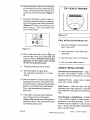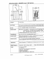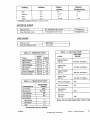
1
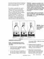
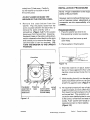
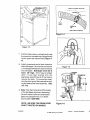
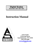
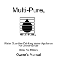
MAV (ATLANTIS) WASHER
INSTALLATION
INSTRUCTIONS
i
SECTION 1. GENERAL INFORMATION
WASHER PRE-INSTALLATION
REQUIREMENTS
NOTE: Proper installation
sibility of the purchaser,
•
Do not store or operate washer in tern
peratures below freezing. This can ¢aus_
damage to the pump, hoses and othe
is the respon-
components. (See page 1-5 for long ten
storage.)
Checkpoints for proper installation:
Water pressure of 20 - 120 P.S.I.is require
to fill the washer in the appropriate tim
frame. Pressuresof less than 20 P.S.I.m_
Properly grounded electrical cutlet is required. Use 15 amp fuse or comparable
circuit breaker for electrical service,
•
Standpipe Drain System must be able to
accept 1½" O.D. drain hose. In cases
where an airtight connectionis required, an
anti-siphoning
valve, part number
12001586,shouldbeplacedinthe drainhose
to prevent siphoningfrom the washer or facilityduringagitation.Standpipeheightof 36"
is recommended,
NOTE: If drain standpipe is in excess of 5 feet
above floor level, install pump accessory kit,
These units are not equippedwith a siphon
break, and the drain hose must be elevated
to a minimum height of 36", For installations with short standpipes, the drain hose
must be supported by clipping the drain
hose into the clip on the back of the
washer. Then a coupler and additional
hose lenghth is added to the eXisting
drain hose.
•
•
Best performance is obtained with tl
washer installed on a solid floor. Wo_
floor constructions may need to be re:
forced to minimize vibration from unb
anted load situations. Carpets and s
tile surfaces are also contributing fact_
in vibration and/or movement during 1
spin cycle, Never install washer on pl
form or weak support structure.
ElectricalRequirements
part number]200]58?
•
cause an extended or exceptionally lot
fill time. Refer to the troubleshooting se
tion for more information regarding a s
lution for slow fill situations.
Hot and Cold water faucets should be
within four (4) feet of the back of the
washer. This allows for quick access for
immediate shut off of the water.
1. Provide an individual 120 volt,
60 HZ, branch circuit with ground f¢
the washer. This circuit must be
rated for 15 amperes or more.
2. Protect the washer's electrical circu
with a 15 ampere time delay fuse c
circuit breaker.
3. Install in accordance with National
Electrical Code and all local codes
and ordinances.
GROUNDING INSTRUCTIONS
•
Water heater should be set to deliver a
minimum of 120° (49°C) hot water to the
washer,
The washer must be grounded. In the
event of a malfunction or breakdown,
16009485
Section1. Generalinformation
@1996 Maytag Corporation
grounding will reduce the risk of electrical
shock by providing a path of least resistance for electrical current,
The washer is equipped with a power
supply cord which has a grounding
conductor and three-prong grounding
plug. For proper grounding, the threeprong grounding plug must be plugged
into an appropriate three-prong
grounded receptacle or outlet (see the
following figure). The receptacle must
be properly installed and grounded in
accordance with the National Electrical
Code and all local codes and ordinances.
WARNING: Improper connection of the
grounding conductor or the three-prong
grounding plug of the power supply cord
cord may result in an electrical shock
hazard, ff there is any doubt as to whetherthe washeris properly grounded, have
the installation checked by a qualified
electrician.
DO NOT MODIFY THE PLUG PROVIDED
WITH THE WASHER - If the plug will not
fit the outlet, have a proper outlet installed
by a qualified technician.
WARNING: For your
safety and to protect
the test equipment,
be sure that the wall
polarized and
grounded.
/_
outlet is properly
r
.
I
1_0 VOL'F5 AC
0 VOLTS
AC
120 VOLT8 AO
Figure 1-2
UNCRATING INSTRUCTIONS
of the washer. NOTE: Retain the corner
NOTE: The following steps must be
performed in the correct order to ease
uncrating.
1. Remove the carton by cutting only marked
areas of the carton. CAUTION: Hoses are
connected to the washer.
2.
Lift the carton and top cap assembly up
and clear of the washer. Carefully remove
any packaging materials from the outside
16009485
posts for later use.
3. Untape and raise the washer lid;
remove the items shipped in the spin
basket. Save the literature for future
reference. Close and retape lid.
4. Place three (3) corner posts and
position them on the floor near the rear
base of the washer. Place the remain*
ing corner post on the floor approxi-
@1998MaytagCorporation
Section1, GeneralInformation
1-2
mately two (2) feet away. Carefully
lay the washer on its back on top of
INSTALLATION
NOTE: Proper installation is the respon
sibility of the purchaser.
the corner posts,
DO NOTLOWER OR RAISE THE
WASHER B Y THE CONTROL PANEL.
4
Remove the crate bottom from the
washer. Pop the plastic loose from the
screw located between the back feet, or
remove the screw entirely with a
screwdriver. (Figure 1-2) Pull the plastic
base away from the back feet. Grasping
the plastic base on the sides, pulling downward to release the front feet from the slots
and toward you to remove the base. Discard the base (it can be recycled). RETURN THEWASHER TO THE UPRIGHT
POSITION.
However,service ca/Is performed as a re
suit of improper setup, adjustment ant
connection are the responsibility of th_
installer.
Proceed as follows:
1. Place the washer as close to its
final operating location as possible.
2. Make sure rear feet move up and
down freely.
3. Place washer in final location.
I
I
Front Feet
__-_1_
Backguard
_i_
_""
' "
__:
_ i_i_'_!_
i1 _,__1
Popplastic
Shipping
(3)
corne_
awayfromor base
Cartoncorner
remove hex
posts (stacked
headscrew
on eachother)
16009485
ir-
Figure 1-2
feet out of base against the floor until 1
4. When the machine is in place, screw fr,
( ' _-_-_11
._
Figure 1-2
PROCEDURE
Iocknut clockwise until the nut is tightened firmly against base. (Figure 1-_
5 washer.machineislevelacr°ssthet°pfr°nt°fi
While holding foot still, turn the adjusti,
6. Tilt machine forward until rear of cabin
pot
is approximately 4 inches off the floor,
then lower the machine back to the flo,
on the rear feet. This operation will
cause the rear stabilizing feet to conf¢
to the contour of the floor and seat the
solidly. Push washerwith hands on
opposite corners to check stability.
(Figure 1-3)
@t998 MaytagCorporation
Section1, GeneralInformation
(Back Of Control Console)
_'_..
_'_.,
i
Beaded Tie
Clip
(Rear Wall of Cabinet
_l _
Figure 1-4
Figure 1-3
7. Pull the drain hose up vertically and snap
the hose into the retaining clip positioned
on the upper rear cabinet wall. (Figure 14)
/
8. Install gooseneck end of drain hose into
drain standpipe. Be sure the connection
is not airtight between the drain hose and
the standpipe. Standpipe must be at
least 36" high. If the hose is twisted
after it has been placed into the
standpipe, adjust the end of the hose to
remove the twist. To remove the twist,
turn the short end of the hose while holding the base of the hose stationary. (Figure 1-5)
Figure 1-5
__
LAUNDRY
:._--"_--_'
_TANDPI!:,E
_ :_
i_.xz,q. "_.r_,-_
__---_- _1
s_:
_:_'_"_"
_,[ 'L;_!__-_ TU S
9 Note: The drain hose should fit loosely
_
_>!II /
in the
standpipevalve
to prevent
siphoning.
(An
anti-siphon
and associated
_)_
_!_- -_1
partSpart
numberare
available12001586).from
your dealer,
U_T
,\ _.
NOTE: BE SURE THE DRAIN HOSE
IS NOT TWISTED OR KINKED.
_?_x
Figure 1-6
16009485
Section1. GeneralInformation
@1998 Maytag Corporation
1-4
14. Secure the drain hose to the standptpe
or drain facility with the cable strap provided. This will ensure the drain hose will
not fall out of the drain facility. (Figure 1-
TOP VIEW OF WASHER
15. Connect inlet hoses to water supply using screenwashers at faucet connections,
with the domed screen facing the faucet.
(Figure 1-7) Tighten hose connections by
hand until snug. Then, turnanother 2/3 of
a turn with the pliers.
<C_
:.
. ,.
" • ' ----'_..,=_'y
_
.. .
"• : •
-_-
Figure 1-8
A_ Faucet Connection
FINAL INSTALLATION CHECK LIST
A,W_,e,w,veCo,,_o,
1. Have all installation requirements
been observed?
Figure 1-7
16. With hoses attached to both th_aucets
and the water valve, turn on the water and
check for leaks. Note the H and C designations on the water valve bracket
for the Hot and Coldhoses.
17. Plug the power cord into an outlet.
2. Have Iocknuts on front feet been
tightened?
3. Are there any kinks in the hoses?
4. Are any water leaks evident?
UNIQUE INSTALLATIONS
18. Start the washer in a spin cycle,
per operating instructions, to center
basket,
Painted/sloped basement floors - Apply nc
slip discs, part number 211692, to the flc
directly under the rubber feet of the washe
19. Startthe washer in awash cycle, as per
operating instructions. Allow water to fill
in machine until it reaches the level of the
Carpeted Floors - Apply carpet installati
discs, part number 204986.
bottom row of holes in the wash basket.
Then, stop the washer by pushing on
timer knob.
12. If the water is not level with the bottom
row of holes all around the basket,
(Figure 1-9)readjust the leveling feet as
required to level. Then remove thewater
by selecting a spin cycle,
16009485
Weak Floors - Install rear legs with plas
grommets,partnumber12001577,to be insert
into baseframeto substitutefor the self adjusti
legs.
Cold Storage or Installations - Installatic
in any location subject to freezing temperatures is not recommended. If the
washer must be installed in such a location, it should be thoroughly drained aftE
each use as follows:
@1998 Maytag Corporation
Section 1, GeneralInformation
1
• Turn off hot and cold water faucets.
• Disconnect both water inlet hoses at
the faucets. Lower them to the floor.
• With the service cord connected to
the electrical outlet, rotate the timer to
the normal start or fill position and
pull timer knob to start washer. Turn
water temperature selector switch to
warm.
• When water stops draining from the
hoses, disconnect service cord.
• Lower the drain hose to the floor and
allow it to drain into a floor drain or
shallow pan.
In below-freezing temperatures, ice may form
in the "fill" flume and the pump. Raise the
room temperature and allow time for the ice
to melt before using the washer.
16009485
Section 1. GeneralInformation
@1998 Maytag Corporation
'1-6
SPECIFICATIONS - WASHER (Lower Half Section)
71.8cm
_"
_
363/8"1
8_.4 _n
°
T
"
68.6em
I
h102err
°
CN '
CAPACITY
3.2 Cubic Feet
ELECTRICAL
120 Volts, 60 Hz; Requires 15 amp circuit breaker or fused electrical supply.
Power cord must be connected to a properly grounded and polarized outlet,
MOTOR
1/2 H.P., reversible,2 Speed, 115 volt, 60 cycle A.C.
POWER USAGE
Motor Input: During Agitation* - 480 Watts Max (Fast)370 Watts Max. (Slov
During Pump Out* - 760 Watts (Fast) 510 Watts Max. (Slow)
Spin - 460 Watts (Fast -Full Tub) 340 Watts (Slow- Full Tub)
[*Wattage readings taken with no dethes in spinner.]
TRANSMISSION
Rack and pinion type, incorporatingreduction gears
WATER USAGE
Water pressure should be 20- 120 P.S.I. (1.06-8.44 kg/cm) at inlet hose
connection, (SEE PAGE 1-8 FOR MORE DETAILS)
HOSE LENGTHS
Four foot inlet hoses with inlet washers attached to water valve.
Drain hose attached to pump and will accommodate 36" high drain stand Pil
DIMENSIONS
Cabinet Dimensions: 27" (68.58cm)Wx27 (68.58cm)D x 43 3/8" (110.2cm
WEIGHT (Approx.)
Uncartoned 160 Ib, (72.6 kg.) Approx.
FINISH
Top Cover- Pome]ain
Lid- Porcelain
OuterTub - constructedentirely of polypropylene
Spin Basket - polypropylene
Cabinet - baked enamel
Base and other finished parts - baked primer
16009485
Crated 185 lb. (84 kg,) Appro
Section1. GeneralInformation
@1998 Maytag Corporation
Setting
Gallons
*Depth
Inches
Mini
10.5
6"
3 1/2"
Medium
14.1
8 1/2"
5"
High
19,5
11"
7"
13 1/2"
9 1/4"
Super
23.3
*Allowable variations are plus or minus 1/2 inch.
AGITATOR
I
SPEED
Regular Cycle
Slow (Delicate) Cycle
SPIN
*Basket
Perforations
88 Oscillations per minute
57 Oscillations per minute
!
i
155 DegreeArc
155 DegreeArc
SPEED
Regular Cycle
Slow (Fine Wash) Cycle
620 R.P.M.
410 R.P.M.
TABLE 1-1. AMPERAGE CHART
WATER
LEVEL
Agitate-Regular
Full Tub
10.4
Agitate-Slow
Full Tub
7.6
Agitate-Regular
Dry Tub
7.5
Spin-Regular
Dry Tub
10.2
Spin-Slow
Dry Tub
7.6
Pump Out-Regular
Full Tub
10.8
Pump Out-Slow
Full Tub
8.0
i *AMPS
TABLE 1-2, RESISTANCE CHART
Timer Motor
Mixing Valve
Cold Solenoid
Hot Solenoid
I
TABLE 1-3, WATTAGE CHART
*WATTAGE
CYCLE
RANG E
CYCLE
COMPONENTS
I
*RESISTANCE
(OHMS)
2360
500-1000
853
867
Agitate-Regular
Full Tub
610-640 / 670 (MAX.)
Agitate-Slow
Full Tub
370400 / 420 (MAX.)
Agitate-Regular
Dry Tub
460-470 / 480 (MAX.)
Agitate-Slow
Dry Tub
350-360 / 370 (MAX.)
Pump Out-Regular
760
Pump Out-Slow
510
Spin-Regular
Full Tub
460
Spin-Slow
Full Tub
340
Drive Motor
High Speed
1.3
Low Speed
Start
2.3
3.1
* These will vary with washer load and line voltag
• These values can vary slightly.
16009485
@1998MaytagCorporation
section1. GeneralInformation
1-8