1
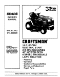
OWNERS
MANUAL
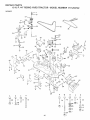
MODEL NO.
917.254722
ERRFTSMRN
Caution:
Read and Follow
All Safety Rules
and Instructions
Before
Operating
YT 18HP TWIN CYLINDER
5
"MOWER
YARD TRACTOR
This ,,Equipment
_,fJ
• Assembly
• Operation
• Maintenance
• Repair and Adjustment
• Repair Parts
Sears,
Roebuck
and
Co.,
Chicago,
tL 60684
U.S.A.
SAFETY
RULES
Know the controls
and how to stop quickly.
READ THIS
23.
Use care when pulling
loads or using heavy equipment.
OPERA TOR'S MANUAL
and instructions
furnished
with
a. Use only approved
drawbar
hitch points,
attachments,
b. Limit loads to those you can safely
control.
2 Do eot altow c_ildren to operate the machine_D_, ,.net allow,_,_ ......
c Do not turn sharply
Use care when backinn
adu _s to operate
f£ wlthodt
f_[oper._nstru_tl_;;
_,_l_';_i::
_:'._
''_-'.t ,_. -:, - . d, Use counterwesght
or wheel weights
when suggest
3 n o h.....
: '
"
=; not€n@
i ,..... ' whet_:_ld'_e_
.....? .......
.,and:.j, .........
Ot cat:ry,passeogers.
O,#
::
.....
"
_n the owner's
manual.
othe_
are_a:r,eSn_:_fi:
_:i_ ,_i
_
....
_ _i'_£"[_!_'_ :i_,_;;:: _iil_t[ 2_,::Watch
out for traffic
when crossing
or near roadways.
4 Always wear"2ub_tantiaf<_o_8_ebr,
Do no£_:_a;=i_S's'e'7ii:
_''........ 2 _J.' When using any attachments,
never direct discharge
of
ring clothing
that could get caught in moving parts,
material
toward
bystanders
nor allow
anyone
near the
5 Keep your eyes and mind on your tractor, mower and the
vehicle
while in operation.
area being cut. Do not let other interests
distract
you,
26, Handle gasoline
with care - it is highly, flammable.
6 Do not attempt
to operate
your tractor or mower
when
a. Use approved
gasoline
containers
,
not _n the drivers seat,
b. Never remove
the fuel cap of the fuel tank or add
7 Always get on or off your tractor from the operator's
left
gasoline
to a running
or hot engine or an engine
that
hand side.
has not been allowed
to cool for several minutes
after
8. Clear the work area of objects
(wire, rocks, etc.) which
running.
Never fill tank indoors,
always
clean up spillmight be picked
up and thrown.
ed gasoline.
9. Disengage
atl attachment
clutches
before attempting
to
c. Open doors if the engine is run in the garage - exhaust
start the engine.
fumes are dangerous.
Do not run the engine indoors,
I O. Disengage
power
to attachments
and stop the engine
27. Keep the vehicle and attachments
in good operating
conbefore leaving
the operator's
position.
dition,
and keep safety
devices
in place and working.
1 t. Disengage
power
to mower,
stop the engine and discon2 B Keep all nuts, bolts and screws tight to be sure the equip.
nect spark plug wire(s)
from spark plug(s) before cleanrnent is in safe working
condition,
rag, making an adjustment
or repair. Be careful to avoid
2 g Never store the equipment
with gasoline
in the tank intouching
hot muffler
or engine components.
side a building
where furnes may reach an open flame or
7 2 . Dtsengage power to attachments
when transporting
or not
spark,
Allow
the engine
to cool before
storing
in any
in use.
enclosure,
t 3. Take all possible precautions
when leaving the vehicle um
30
To reduce fire hazard, keep the engine free of grass, leaves
attended.
Disengage
the power4ake-off,
lower the ator excessive
grease.
Do not clean product
while engine
Js running.
tachments,
shift into neutral,
set the parking
brake, stop
the engine and remove
the key.
3 _. Except
for adjustments;
DO NOT operate
Engine if air
7 4. Do not stop or start
suddenly
when going,
uphill
or
efeaner
or cover
d_rectlF
over carburetor
air intake
is
downhill,
Mow
up and down
the face of slopes
(not
removed.
Removal of such part could create a fire hazard.
greater than t 5 o); never across the face. Refer to page 51.
32. Do not operate
without
a muffler
or tamper with exhaust
75. Reduce speed on slopes and make turns gradually
to presystem. Damaged
mufflers
or spark arrestors
could create
vent tipping
or loss of control.
Exercise extreme
caution
a fire hazard. Inspect' periodicafly
and replace if necessary.
when changing
direction
on slopes.
33. The vehicle and attachments
should be stopped
and in-.
16. While going up or down slopes, place Gear Shift Control
spected
for damage after striking
a foreign object and the
Lever in 1st gear position
to negotiate
the slope without
damage should be repaired before restarting
and operati,,
stopping.
the equipment.
17. Never mow in wet or slippery grass, when traction
is un34. Do not change the engine governor settings
or overspeed
sure or at a speed
which could cause a skid.
the engine;
severe damage
or injury may result.
7 8. Stay alert for holes in the terrain and other hidden hazards.
35. When using the vehicle with mower,
proceed
as follows;
Keep away
from drop-oils.
a. Mow only in daylight
or in good artificial
light,
7 9. Do not drive
too close to creeks,
ditches
and public
b Shut the engine off when unclogging
chute.
highways.
c. Check the blade mounting
bolts for proper
tightness
2 O, Exercise special care when mowing
around fixed objects
at frequent
intervals.
in order to Prevent
the blades from striking
them. Never
36. Do not operate the mower
without
the deflector
shield in
deliberately
run tractor or mower into or over any foreign
place.
objects.
37. Disengage
power
to mower
before backing
up. Do not
21. Never shift gears until tractor
comes to a stop.
mow in reverse unless absolutely,
necessary
and then only after careful observation
of the entire area behind the
22. Never place hands or feet under the mower,
in discharge
chute or near any, moving
parts while tractor
or mower
mower,
are running.
Always
keep clear of discharge
chute.
38. Under normal usage the grass catcher bag mater/at is subject to deterioration
and wear. It should be checked
fre_
quentty
for bag replacement.
Replacement
bags should
be checked
to ensure
compliance
with
the original
manufacturer's
recommendations
or specifications.
SAFETY PRECAUTIONS.
IT MEANS - ATTENTION!
BECOME
LOOK
FOR THiS SYMBOL
TO POINT OUT IMPORTANT
ALERT! YOUR SAFETY IS iNVOLVED,
CAUTION:
LOOK FOR THiS WORD TO POINT OUT IMPORTANT
MENT PRECAUT!ONS.
EQUIP-
This unit is equipped
with an internal
combustion
engine
and should
not be used on or near any unimproved
covered, brush covered
or grass covered land unless the engine's
exhaust
system
is equipped
with a spark
meeting
applicable
!oca/ or state laws (if any). If a spark arrestor
is used, it should be maintained
in effective
order by the operator,
In the State
Other states
of CafifornJa
the
may have similar
above
laws.
forest
afros"
work
is required
by law (Section
4442
of the California
Public
Resources
Code),
Federal
taws appty on federal
lands.
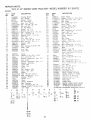
Refer to Repair Parts Section
page 34.
CONGRA TUt.A TfONS on your purchase of a Sears teHP
Yard Tractor.
tt has been designed,
engineered
and
,manufactured
to give you the best possible dependability
and performance.
SERIAL
NUMBER
DATE OF
PUR_CHASE
ohou/d you experience any problem you cannot easily
remedy, ptease contact
your nearest Sears Service
Department.
We have competent, weft-trained technicians and the proper tools to service or repair this unit.
MAINTENANCE
A Sears
product,
THE SERIAL
NUMBER
MODEL
PLATE
UNDER
WILL
BE FOUND
THE SEAT,
YOU SHOULD
RECORD
THESE
KEEP FOR FUTURE
REFERENCE,
A GREEMENT
Maintenance
Agreement
is available
See the nearest Sears store or Service
ON THE
NUMBERS
AND
on this
Center
for details,
CUSTOMER
RESPONSIBIMTIES
Read and retain this manual Study and observe the safety rules. Always use care when using your tractor. Always
keep your tractor and mower clean, Follow a regular schedule in maintaining, caring for, and using your tractor. A
we//cared for tractor wi/! run better and last longer.
A TTA CHMEN
TS
This unit can use many attachments
now available at your Sears store. It can use a tifler, but cannot use other attachments
that engage the ground like a ptow, harrow, or cultivator. See page 50 for a list of available attachments.
LIMITED
ON ELECTRIC
TWO YEAR WARRANTY
START
RIDING
EQUIPMENT
For two years from date of purchase,
when this riding equ;pment
is maintained,
lubricated,
according
to the operating and maintenance
instruction
in the owner's manual, Sears will repair
any defect
in material
or workmanship
in this electric
start riding equipment.
This warranty
excludes
blade!s),
blade
dable and become
worn during normal
This
adapterfs),
use.
spark
pfug(s),
aft cleaner
and belt(s),
which
warranty
does not cover:
Tire replacement
or repair caused by punctures
from outside objects (such as nails,
or glass); and
repairs necessary'
because of operator
abuse or negligence,
including
the failure
equipment
according
to instructions
contained
in the owner's
manual;
and
riding equipment
used for commercial
or rental purposes.
FULL
For 90 days from the date
in material
or workmanship
the battery
at no charge.
WARRANTY
SERVICE
MENT IN THE UNITED
This warranty
to state.
SEARS,
gives
90-DAY
WARRANTY
of purchase,
if any battery
and our testing determines
IS A VAtLABLE
BY CONTACTING
STATES.
This warranty
applies
you specific
ROEBUCK
legal rights,
ON
are expen-
thorns,
stumps,
to mmntain
the
BATTERY
incfuded
with this riding equipment
the battery
will not hold a charge,
proves defective
Sears wilt replace
THE NEAREST SEARS SERVICE CENTER/DEPARTonly while this product
is in use in the United States,
and you may also have other
AND CO., Di731CR-W
and tuned up
free of charge
SEARS
TOWER,
rights
which
CHICAGO,
may
vary from
ILL. 60684
state
iNDEX
A
Fuel:
Adjustments:
Brake
Carburetor
Mower
Drive Belt
Mo wet
Front-To-Rear
!7
22
I1
t3
25
22
Type
Storage
Fuse
23
Side- To-Side
Throttle
Control
Cable
Air Cieaner
Cleaning
Paper Cartridge
Air Intake Screen,
Engine
Assembly
Attachments
.......................
23
2t
t8
I8
19
5-1 l
50
H
Hood
Parts
Lubrication:
Chart
Tractor
Pivot
Prepara tion
Starting
with
Storage
Terminals
Air
8
18
Air Intake
Battery
7
Weak
Battery
Drive
Drive
Drive,
Replacement
Adjustment
Removal
22
11
10
Carburetor
Controls,
Cutting
Adjustment
Tractor
Level,
Mower
Screen,
Cartridge
Engine
Front-to-Rear
Cutting
Level
Installation
22
12
Operation
Removal
Muffler
23
Spark
Arrester
16-20
18
t8
!9
18
17
17
16
20
19
17
23
23
17
24
1I
10
14
23
19
2
0
E
Oil
Engine:
Air Screen
Oil Change
Oil Level
Oil Type
Starting
Storage
Cold
I9
18
I6
16
t3
25
Weather
Conditions
Engine
Storage
Operation
Operating
Your Mower
Operating
Your Tractor
Starting
the Engine
4
Bag
50
2
5,6
Repair and Adjustments
Blade
Carburetor
Fuse
Hood
16
16
25
12-15
t4
14
13
20_24
24
22
22
Removal
23
Motion
Mower
Drive Bett
Adjustment,
Mower
Mower
Adjustment,
Removal
Replacement
Front-to.Rear
Side.to.Side
22
23
23
23
S
Safety
Seat
Service
Adjustment,
Side.to_Side
Blade Sharpening
Blade Replacement
17
C
Paper
Spark Plugs
Tire Care
Mower.
Adjustment,
I7
24
Sharpening
Reptaeement
Brake Adjustment
Cleaner
Blade Sharpening
Brake Adjustment
Engine Oil
Lubrication
Chart
2!
25
t8
Belt:
Motion
Mower
Mower
Blade:
Maintenance
Air Filter
18
...................
...................
2O
19
Points
M
2!
Options
Attachments
Spark Arrester
13
I5
23
Removal
B
Battery;
Charging
Cleaning
Installation
Levels
Stopping
Your Tractor
Tractor
Operation
on Hills
Slope
Spark
Rules
2
Record
Guide
Plugs
2,
Sheet
51
19
Speed Control
Chart
Starting
the Engine
Steering
Wheel
Stopping
the Tractor
t4
13
8
13
Storage
25
T
Throttle Control Cable Adjustment
Tires
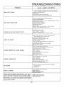
Trouble Shooting Chart
2t
17
26
W
Warranty
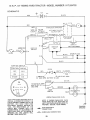
Wiring (Schematic)
3
29
KNOW
YOUR
ASSEMBL Y
TRACTOR
READ THIS OWNER'S
MANUAL
BEFORE OPERA TING YOUR YARD TRACTOR.
If you
e machine
and its operation,
you will achieve
efficient
and peak performance.
While
manual,
compare
the illustrations
with your Yard Tractor
to familiarize
yourself
with
of various
controls
and adjustments.
Study
the operating
instructions
and safety
thoroughly
to insure proper
functioning
of your Yard Tractor
and to prevent
injury to
others.
Be sure to pay strict attention
to all notes and cautions;
they are included
for
Save this manual
for future
reference.
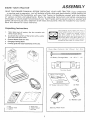
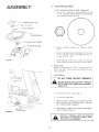
Unpacking
1.
Instructions
Take items out of carton;
items she wn bole w.
2.
understand
reading
the
the location
precautions
yourself
and
your safety.
the box
contains
3.
Cut down four corners of the carton
knife and fold down sides.
Remove Mower Deck from skid.
4.
5.
Disengage Parking Brake
Carefully guide the tractor backwards off the skid.
The operation
of any tractor
can result in
foreign objects thrown
into t,he eyes, which
can result
in severe eye damage.
Always
wear safety glasses or eye shields before
starting
your tractor and while mowing.
We
recommend
Wide Wsion Safety Mask worn
over spectacles
or standard
safety glasses,
available at Sears Retail or Catalog Stores.
the
with a ud/ity
Parts
Bag
Contents
(2) Battery
Carriage
Not
Bolts
Shown
Full
- 1/4 - 20
Size,'
x 7 _ t/2
d.
Terminal
15 ° Slope
Instruction
Guard
Sheet
(2) Keys
)
(6)
_. Best
b.
steering
wheel
d. battery
acid
e. owner's
manual
f. parts bag
Steering
Wheel
Insert
Battery
Caps
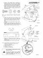
ASSEMBL Y
A SSEMBL Y
L OCA TION
PARTS
BAG
CONTENTS
SHOWN
FULL
SiZE
BA TTER Y
(2) Wing
Nut
- 1/4 - 20
©
BA TTER Y
TERMINAL
S
(2) Hex Bolt,
1/4-
20x
3/4
(2) Lockwasher
(2) Washer
9/32
x 5/8 x
I/4
16 Ga.
Q
(2) Hex Nut,
(!) Hex Bolt, 1/2-
13x
- 20
©
1
(1) Lockwasher,
SEAT
1/2
fl)
(1) Shoulder
!/4
Bolt
6
Washer,
17/32x
1-3/16x
12 Ga.
To assemble
and
(2J
(1)
(1)
(1)
(1)
adjust
your tractor
7/16" wrenches
9/t6"
wrench
1/2" wrench
3/4" wrench
3/4" socket
you
ASSEMBL Y
will aeed:
Tire Pressure Gauge
Screwdriver
Utility Knife
Ratchet Wrench
CUT AWAY VIEW
--
VENT
CAP
cz:::::cy _
BATTERY
TUBE
NOTE: RIGHT HAND (R,H.) AND LEFT HAND (LH.) ARE
DETERMINED
FROM OPERATOR'S
POSITION
WHILE
SEATED ON THE TRACTOR.
WEAR
EYE AND
FACE
BATTERY
CELL
SHIELD.
WASH
HANDS OR CLOTHING
IMMEDIATELY
IF ACCIDENTALLY
IN
CONTACT
WITH BATTERY
ACID.
DO NOT SMOKE;
FUMES
FROM
CHARGED
BATTERY
AC1D ARE
EXPLOSIVE,
READ THE INSTRUCTIONS
INCLUD*
ED WITH
THE BATTERY
VENT
CAPS IN THE BAG OF PARTS.
ALWAYS
WEAR GLOVES,
CLOTHING
AND GOGGLES TO PROTECT YOUR
HANDS, SKiN AND EYES.
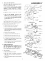
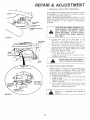
1.
Prepare
a.
b,
C,
d,
e.
f _
FIGURE
I
FIGURE
2
SHOUL
BOLT
S_AT
PAR
Battery
Fill and charge battery (before installing). NOTE:
SEE DETAILED INSTRUCTIONS PACKAGED
W! TH BA TTER Y VENT CAPS IN BAG OF PARTS.
Fit! each ceil with battery acid, Add the acid um
til it reaches the bottom
of the vent wells (Fig,
1), NOTE: DO NOT OVERFILL,
OVERFILLING
WILL RESULT tN DAMAGE
TO TRACTOR.
Allow battery to stand and settle for at least thirty minutes.
If the level of acid falls below the
point described
in step (b), add more acid until
the correct
level is reached,
NOTE: UNEVEN
FILLING OF CELLS WILL AFFECT THE BATTERY
CAPACITY
AND LIFE. install the battery caps to
cover the vent wells, Wash the top of the battery witl_ water to remove any acid, then wipe
dry.
,
Install Seat
a,
b.
Check battery case for leakage to make sure that
no damage
has occurred
in handling,
tt is recommended that the battery be charged before
use. Use a 12 volt battery charger. Charge battery at a
rate of 6 amperes for 1 hour. NOTE: OBSERVE ALL
SAFETY PRECAUTIONS REQUIRED FOR BA 77ER Y
CHARGING. Check the acid level after the battery is
charged. If the acid has fallen below the correct level,
add water.
Neutralize excess battery acid for disposal by
adding it to four inches of water in a five
gaflon plastic container. Stir with a wooden or
plastic paddle while adding baking soda until
the addition
of more soda causes no more
foaming.
Place seat on seat pan. Screw hex head machine
screw, tockwasher and flat washer into seat (Fig.
2). Screw shoulder bolt into seat (Fig. 2). Machine
screw, shoulder bolt and washers found in bag of
parts (shown full size on page 6).
Tighten shoulder bolt using a 1/2" wrench. NOTE:
THE SHOULDER BOL T WILL BE LOOSE IN THE
SEAT PAN SLOT.
C,
Place seat in operating position. Sit on the seat
and press c/utch/brake
pedal a// the way down.
If operating position is not comfortable,
adjust
seat.
d,
To adjust, raise seat. Loosen adjustment
boil
(Fig, 2) and slide seat to a comfortable
operating position. Tigh ten adjustment bolt securely
using a 3/4 "" wrench.
ASSEMBL Y
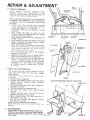
3.
Insta# S{eering
Wheel
NOTE: POSITION FRONT WHEEL FORWARD,
a. Use a 3/4"
wrench
to remove
lock nut, and
2- 1/4'" diameter washer (shown full size below)
from steering
column (Fig, 3).
" STEERING
HEX
_f
2-
WHEEL
LOCK
1i,'D,A,
NUT
WASHER
-_STEERING
FIGURE
CAP
WHEEL
iNSERT
3
b
Position
insert,
c
Secure
steering
2-1/4"'
diameter
Torque
to
d.
4.
HOOD
5.
steering
wheet
wheel
50
steering
to steering
washer
ft
over
and
column
lock
nut
3),
- Ibs.
Check Tires
Reduce tire pressure to 14 PSi in front tires and 12
PSI in rear tires, (Tires were overinflated
for shipping purposes):
install
Battery
NOT
SHORT
BATTERY
TERMINALS
BEFORE INSTALLING
BATTERY,
METAL BRACLETS, WRISTWATCH
RINGS, ETC.
from
rear sides
(Fig,
REMOVE
BANDS,
a.
Lift
hood
b.
Lift
out air intake
c.
Make sure drain tube (Fig. 5) is fastened
to drain
hole in battery
tray and battery tray is positioned in hole of battery
support,
d,
Place battery in plastic
front of tractor)
(Fig,
GRILL
FIGURE
using
(Fig.
Snap steering
wheel cap in place on steering
wheel. Steering wheel cap found in bag of parts,
DO
BATTERY
COMPARTMENT
wheel
4).
duct.
tray
5),
(battery
terminals
to
4
POSITIVE
TED
FIRST
ACCIDENTAL
8
TERMINAL
TO
MUST
PREVENT
GROUNDING.
BE
SPARKS
CONNEC-]
FRO_¢
j
ASSEMBL Y
e. Connect RED battery
cable to posit/re
(+)
battery
terminal
with hex bolt, flat washer,
/ockwasher and hex nut (shown full size below)
found in bag of parts (Fig. 5). Tighten securely.
f. Connect BLACK ground cable to negadve (-)
battery terminal with remaining hex bolt, flat
washer, /ockwasher
and hex nut (shown futt
size below)
found in bag of parts (Fig. 5).
Tighten securely.
NOTE:
IF YOU HAVE
A WEAK
tNG
YOUR
TRACTOR
WITH
(PAGE
BATTERY,
A WEAK
NUT
OCKWASHER
WASHER
SEE "STARTBATTERY"
WASHER
/ ,_
2! ).
BATTERY
TERMINAL
g. Using the dotted
hole on one side of the
battery support (Fig. 6) insert one battery bolt
into frame slot (head of bo/t down). Fasten the
battery bolt to the termina/ guard using wing
nuts.
(Bolts, nuts and terminal guard found in bag
of parts).
h. Assemble the remaining bolt to other side of
battery support and fasten terminal guard to it
with remaining
wing nut (shown furl size below).
Tighten wing nuts securely by hand (Fig. 6).
BOLTS
HEX
BLACK
(NEGATIVE)
CABLE
TRAY
DRAIN
FIGURE
ERMtNAL
ACCE_
DOOR
TERMINAL
GUARD
TERMINAL
ACCE_
DOOR
L Replace air intake duct (Fig. 4). Make sure
bottom lip of duct sits between battery and lip
of battery tray.
j. Remove plastic from tractor hood and close.
NOTE : USE TERMINAL
ACCESS DOORS (FIG. 6) FOR:
1 • INSPECTION FOR SECURE CONNECTIONS
(TIGHTEN HARDWARE)
2. INSPECTION FOR CORROSION
3. TESTING BATTERY
4. JUMPING (IF REQUIRED)
5. CHARGING (IF REQUIRED)
KEEP TERMINAL
ACCESS DOORS CLOSED
WHEN NOT iN USE.
DO NOT START ENGINE UNTIL MOWER
SUSPENSION
BRACKET
HAS BEEN RELEASED,
SEE MOWER AND DRIVE BELT
INSTALLATION,
PAGE 10.
BATTERY
BOLT
BATTERY
SUPPORT
BATTERY
BOLT
i
SLOTTED
HOLE
k
\
FIGURE
,5
5
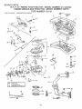
ASSEMBL Y
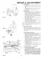
6.
Mower
tnsta#ation
Your 44_'mower
CLUTCH
ROD
'\
RETAINER
\
SUSPENS{ON
ARM
SPRING
CLUTCH
LEVER
t
.__.J
J_
\
RETAINER
/
/
_\
./
TRUNNION
/
J
b.
Turn height adjustment
knob counterclockwise
(.f"..)
to fewest position
tFig. 9).
c.
Slide mower
R.H. side.
d.
install
under
9) to its highest
tractor,
position.
discharge
guard
to
;-newer
hft brackets
/
/
/
use of tools.
/
/
/
/
/
(Fig.
the
Raise
SPRING
lift lever
without
a.
\
--_"
installs
,"ear hinge pin through
PARALLEL
/
/
spring.
LINK
i
e
Instal! clutch
with :etainef
Move
8F,'_S
lift
rod in clutch
spring.
,'ever
lever
forward
iF,g.
tO lower
7!.
Secure
Suspens..on
.
LIFT
R E T A'it',_ E R
BRACKET
DISCHARGE
GUARD
SPRING
FIGURE
g,
7
ENGIN_
PULLEY
/
Slide
trunnion.s through
and secure w/t!b retainer
_ear L,ft bracket
spring,'Fig.
71.
l_o_es
h.
Roll belt over engine pulley.
Make sure t_elt ls
reside belt guides IF_g. 81. See belt drive sche
rnat_c decal on mower housing.
.'
Use lift lever
i
Turn ,,height ady'ust?,',ent knob u_oekw;se
the m_ddle of ds travel.
to ra;se
i71ower.
i.--_i
to
/
7. Mower
Drive
REPLACE
MANUAL.
ONLY
L}FT
ATTACHMENT
"DISENGAGED"
CLUTCH
POS1T!ON
LEVER
--.-...
"'HIGHEST
LEVER
BELTS
clutch
SPECIFIED
lever
in
IN
b.
Turn height adj_stment
i_nob counterclockwise
_r",i
to lowest position.
c.
Move attachment
lift lever
lower mower
to its lowest
THIS
'disengaged"
"
POSITION
/
CLUTCH
LEVER
POSiTiON
WITH
Place attachment
position
!_ig. 9}.
8
ATTACHMENT
"ENGAGED"
Removal
a.
\
FIGURE
Belt
LIFT LEVER
"LOWEST"
POSITION
d. Roll
belt
off engine
!Fig.
9) forward
to
positiof'!.
pulley
{Fig.
8i.
/
e
Use t,2'
wrench
to loosen
two nuts on
belt guard.
Pui/ belt off pulley
(Fig. 10t.
.q H.
f.
Use 9_t6"
wrench
to loosen nut on
pulley.
Puft belt off pulley (Fig.
10).
id!e,
g.
Slide
h.
To replace mower drive belt. reverse above pro
cedure.
Make sure drive belt iS inside mower
drive pulley belt guides (Fig. 8).
2
//
/'/
/-/
//
//
//
/
bett from
under
L.H.
spring.
#/
b
HEIGHT
ADJUSTMENT
/
NOTE:
BELT GUIDE TO BELT CLEARANCE
MAINTAINED
AT 5/32"
to t/4".
/
KNOB
FIGURE 9
10
SHOULD
E'
,
Mower Drive Be# Adjustment
Your tractor
has been manufactured
with the
ability
to re-adjust
the mower
drive belt to
provide you with longer belt !ire.
If the attachment
clutch lever (Fig, 9) travels
3-1/2" up the slot in the dash before sp.ring tension
resistance is evident,
adjustment
_s necessary.
NOTE: CHECK FOR PROPER SPRING TENSION
WITH
ENGINE
OFF AND LIFT LEVER IN HIGHEST
POSITION.
a. Lower
or remove
the mower
SPRING
deck for easier
access,
b, Using (2)7/16"wrenches,
remove the two
washers from the rock shaft assembly (Fig. t 1).
c. Move extension spring from lower end of slot
to upper end in rock shaft assembly and install
the two washers (Fig. 11).
d, Tighten bolt and nut to secure the washers,
NOTE:
WHEN
INSTALLING
A NEW BELT,
EXTENSiON SPRING MUST BE RETURNED TO THE LOWER
END OF THE SLOT ON ROCK SHAFT
ASSEMBLY,
9, Replace
Mower
FIGURE
10
EXTENSION2PR1NG
Blade Drive Belt
a, Remove mower from tractor
BRAKE
(page 23),
ROO_
ROCK
SHAFT
eLY
b, Remove mower drive belt (page 10),
c, Puff belt towards rear of mower at tensioning
pulley. Place a block between tension brackets
and spring brackets. Ro/! belt off tensioning
pulley (Fig, 12),
LOWER
HOLE
{ORIGINAL
POSITION)
COTTER
BRACKET
"J-j/_--_k
OC K N UT
d, Rofl belt offal/otherpu/leys.
FIGURE
11
e. Use priers to remove brake spring (Fig. 13).
f, Remove cotter
)WER
pin from brake rod (Fig, 11),
BLADE
BELT
g, Puff bett out from under brake rod of mower.
h. To instal/ belt, reverse above procedure.
sure belt is engaged in at/ pulleys.
Make
L Replace brake springs, brake rod and retainer
spring, Tighten two nuts on belt guard and nut
on L,H. id/er pu//ey (Fig. !0),
10,
Check
the Cutting
Level
The blade housing was set at the factory to cut
level After mowing a short distance, look at the
area that was cut, /f the Made housing cuts
uneven; see the instructions
on "Side-to Side and
Front-to-Rear
Mower Adjustment"
(page 23),
BLOCK
TENSION
BRACKET
SPRING
BRACKET
l
TENSIONING
"_- PULLEY
FIGURE
//
11. Final Assembly
a, Make sure aft fasteners are tight.
b. Read and follow
the operation
instructions
(page 12). Know the /ocadon and purpose of
all controls.
c, Check off and gasofine (page 13) before starting
the tractor,
BRAKE
SPRING
12
OPERA T?ON
KNOW
YOUR TRACTOR
READ THiS OWNER'S
MANUAL
BEFORE OPERATING
YOUR YARD TRACTOR.
operation,
you wil! achieve efficient
and peak performance.
While reading the
your Yard Tractor to familiarize
yourself with the location
of various controls
instructions
and safety precautions
thoroughly
to insure proper functioning
of
to yourself and others. Be sure to pay strict attention
to all notes and cautions;
this manual for future reference.
tf you understand
the machine and"
manual, compare the illustrations
with
and adjustments.
Study
the operating
your Yard Tractor and to prevent
injury
they are included
for your safety.
Save
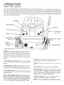
Ammeter
Light
Switch___
Throttle
Ignition
con
©
Attachment
//
Choke
Lift
Clutch/Brake
Pedal
Lever
Attachrnent
Lever
Clutch
Height
Adjustment
Knob
Gear
AMMETER:
ammeter.
Shift
----"
Lever
"
_
_J
Each time you start your tractor_ check your
The needle should move towards
the (÷)
charging
mark indicating
the battery is being charged as
you operate the tractor,
The headlights
will not show a
discharge
on the ammeter
because
they are not connected
to the battery
(they have their own electrical
source).
GEARSH?FT:
Press the ctutch/brake
pedal down
and move gear shift lever to desired speed.
A TTA CHMENT CLUTCH LEVER: Push te vet up to engage
mower.
There wif! be an engine hesitation
as the clutch
engages.
?GNfT?ON: Place key in ignition
start.
and turn
firmly
to the right
to
ATTACHMENT
LIFT LEVER: Use the attachment
lift lever
to raise and lower the attachment
mounted
to your tractor. Move the lift level" forward
to lower attachment.
LIGHT
CLUTCH!BRAKE
PEDAL:
The pedal has 2 functions:
a
clutch and a brake.
To engage the brake push the pedal
completely
down,
PARKING
BRAKE: To set the parking
brake, push the
ctutch/brake
pedal completely
forward.
Place the parking brake lever in "'Engaged"
position
and release
pressure
from pedal. Clutch/brake
pedal will remain in
brake position.
To release, push pedal in.
HEDGHT ADJUSTMENT
KNOB: Use the height adjustment knob to adjust the mower height. With the attachment lift lever in the "'up'" position,
turn knob clockwise
(/_)
to raise cutting height and counterclock
wise (f-",)
to lower cutting
heLght. Lower Attachment
lift lever.
SW?TCH:
Turns
on and off
the headlights.
THROTTLE
CONTROL:
Use the throttle
control
crease or decrease
the speed of the engine.
CHOKE:
I2
To start
a cold engine,
pull choke
to in-
out to engage.
1.
Stopping
CAUTION:
OPERA TION
Your Tractor
DO NOT CHOKE CARBURETOR
THE ENGINE
OTE: REMOVE
KEY WHEN LEAVING
, REVENT UNAUTHORIZED
USE.
TO STOP
TRACTOR
AIR INTAKE
DUCT
TO
a.
Push clutch/brake
pedal
into
full
"'BRAKE"
position.
b. Move gear shift lever to "NEUTRAL"
position.
c. Place parking brake in "ENGAGED"
position
and
release pressure
from clutch/brake.
Pedal should
remain in "BRAKE"
position.
NOTE: MAKE SURE
PARKING
BRAKE
WILL
HOLD
TRACTOR
SECURE,
d. Place attachment
clutch lever in "'DISENGAGED"
position.
e. Move throttle
control to "S" (stow) position.
f. Turn ignition
key to "OFF"
position.
Never use
choke to stop engine.
2,
Starting
FIGURE
14
SEAT
The Engine
©
i
ADJUSTMENT
LEARN TRACTOR
YOUR
TO START,IN ASTOP
LARGE,
ANDOPEN
REVERSE
AREA,
it i!i
THIS TRACTOR
IS EQUIPPED
WITH INTERLOCK SWITCHES TO PREVENT STARTING OF THE TRACTOR
ENGINE WHILE
THE MOWER BLADE CLUTCH LEVER mSIN
THE "ENGAGED"
POSITION AND/OR THE
FOOT PEDAL IS NOT FULLY DEPRESSED.
IMMEDIATELY
REPLACE SWITCHES THAT
ARE rIOT IN PROPER WORKING
ORDER,
DO NOT ATTEMPT
TO DEFEAT THE PURPOSE OF THESE SWITCHES,
1
FIGURE
FtLL TO 8OTTOM
OF GAS TANK FILLER
NECK. DO NOT OVERFILL.
WIPE OFF ANY
SPILLED OIL OR FUEL, DO NOT STORE,
SPILL OR USE GASOLINE
NEAR AN OPEN
FLAME,
a.
This engine has been shipped filled with summer weight oi/. For cold weather operation,
see chart on page 16. Check engine oil level
with tractor on level ground.
Remove and
wipe dipstick (Fig, 14) clean, screw it in tight
for a few seconds, remove and read oi/level,
/f necessary, add off until "FULL " mark is
reached.
b. Fifl fuel tank. Use fresh, clean, regular UNLEADED automotive
gasoline, (Use of leaded
gasoline wi// increase carbon and lead oxide
deposits and reduce valve life). Capacity is
3-1/2 gallons.
c
Place attachment
clutch
lever in "'disengaged"
position
(Fig, 17).
d_ Push clutch/brake
pedal fully into brake position,
e, Place gear shift lever in "'NEUTRAL "' positon (Fig.
17).
f,
g
h
CAUTION:
EXPERIENCE
INDICATES
THAT ALCOHOL.BLENDED
FUELS (CALLED
GASOHOL
OR USING ETHANOL
OR METHANOL)
CAN ATTRACT
MOISTURE
WHICH
LEADS TO SEPARATION
AND FORMATION
OF AC_
_DS DURING STORAGE.
ACIDIC GAS CAN DAMAGE
THE FUEL
SYSTEM
OF AN ENGINE
WHILE
EN
STORAGE.
Pull choke out (Fig.
Move throttle control
17).
to middle
position
(Fig.
t 7).
Turn ignition
key clockwise
(/_)
to "START'"
position and release key as soon as engine starts.
NOTE: DO NOT RUN STARTER CONTINUOUSLY
FOR MORE
THAN
FIFTEEN
SECONDS
PER
MINUTE. If engine does not start after several attempts,
position,
TO AVOID ENGINE PROBLEMS,
THE FUEL SYSTEM
SHOULD
BE EMPTIED
BEFORE STORAGE
FOR 30
DAYS OR LONGER,
DRA_N THE GAS TANK, START
THE ENGINE
AND LET IT RUN UNTIL THE FUEL
LINES
AND
CARBURETOR
ARE
EMPTY,
USE
FRESH FUEL NEXT SEASON,
SEE STORAGE
INSTRUCTIONS
FOR ADDITIONAL
iNFORMATiON.
NEVER USE ENGINE OR CARBURETOR
CLEANER
PRODUCTS
IN THE FUEL TANK OR PERMANENT
DAMAGE
MAY OCCUR,
t 5
move
throtde
control
to
wait a few minutes
and try
"F" (fast)
again.
NOTE: tF YOU HAVE A WEAK BATTERY,
SEE "STARTING
YOUR
TRACTOR
WITH
A WEAK
BATTERY"
(PAGE 21 ).
i.
13
After
engine is warm, push choke in. The first
time you start the engine, it wilt take extra cranking time to move fuel from tank to _he engine,
OPERA TION
3. Operaft#_g Your "fr_ctor and f!_e_er
NOTE:
THIS
TRACTOR
IS EQUIPPED
WiTH
AN
OPERATOR
PRESENCE SENSING SWITCH,
ANY AT_
TEMPT BY THE OPERATOR TO LEAVE THE SEAT WITH
THE
ENGINE
RUNNING
AND
THE
ATTACHMENT
CLUTCH ENGAGED WILL SHUT OFF THE ENGINE,
NOTE: ALLOW ENGINE TO WARM UP FOR A
FEW MINUTES BEFORE ENGAGING CLUTCH OF
TRACTOR OR ATTACHMENT.
When restarting a warm engine, move throttle
control
midway
between
"S" (slow)
and
"'F" (fast) positions.
Choke may not have
ro be used.
j,
IMPORTANT:
FUNCTION
Normat
Mowing
Heavy
Mowing
SNOW
Blade
Snow Bbower
or Tiller
BEFORE
INSTALL
MOWER
DR_VING
MOWER
PARALLEL
GEARSHIFT
CAUTBON
TO AVOID
THE TRACTOR,
OR REMOVE
LINK,
THROTTLE
2or3
1or2
t,2or3
!
MAKE SURE PARKING
TRACTOR
SECURE.
_J_L.
Transport
INJURY
1, Read owner's
manual.
2. Know the locadon
and function
of all controls,
3, Keep guards, safety shields and switches
in place
and working.
4. Remove objects that can be thrown
by blades.
5, Do not mow when children and others are around.
6. Never carry children or passengers,
7, Always
look behind machine
before backing.
8, Do not mow where machine
can tip or slip,
9. If machine stops going uphill, stop blade and back
slowly down,
10. Be sure blades and engine have stopped before ptacing hands or feet near the blades,
1!. Remove key when leaving machine,
WILL HOLD
NEVER PLACE YOUR HANDS OR FEET iN
OR UNDER ANY POWERED ATTACHMENT
OR NEAR ANY
MOVING
PART WHILE
TRACTOR
OR ANY POWERED
ATTACHMENT IS RUNNING.
3,4or5
SLOW
BRAKE
FAS]
NOTE: ALWAYS OPERATE ENGINE AT FULL THROTTLE
WHEN MOWING
TO ASSURE
BETTER MOWING
PERFORMANCE
AND PROPER DISCHARGE
OF CUT MATERIAL, REGULATE GROUND SPEED BY SELECTING A
LOW ENOUGH GEAR (TABLE 1) TO GIVE THE MOWER
CUTTING
PERFORMANCE
PLUS QUALITY
OF CUT
DESIRED
DO NOT OPERATE THE MOWER WITHOUT EITHER THE ENTIRE GRASS
CATCHER,
ON
MOWERS
SO
OR THE DEFLECTOR
SHIELD IN PLACE.
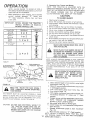
a,
FIGURE
Select desired height of cut position
adjustment
knob (Fig, 17),
b, Raise rift lever and place attachment
in disengaged
position.
16
TION"
READ
YOUR
THE
CAREFULLY
"RULES
MOWER.
BEFORE
FOR SAFE
OPERATING
OPERA-
c.
d,
e.
THE MOWER MUST BE ADJUSTED
PROPERLY
FROM
FRONT TO REAR AND LEVELED FROM SIDE TO SIDE
BEFORE OPERATING. THIS tS NECESSARY FOR LEVEL
AND EFFICIENT MOWING. REFER TO PAGE 23.
CAUTION:
using height
clutch
lever
Push clutch/brake
pedal down firmly
(Fig, 16).
Start engine (page t3).
With engine running and warm place throttle control midway
between
"'S'" (slow) and "'F'" (fast)
position,
f . Engage mower
with the attachment
clutch lever.
NOTE: "ENGAGE"
OR "DISENGAGE"
MOWER
BLADE CLUTCH
LEVER SLOWLY.
DO NOT ADD ADDITIONAL WEIGHT TO
THE TRACTOR OTHER THAN THE OPTIONAL WHEEL WEIGHTS° EXCESSIVE
WEIGHT MAY OVERLOAD AND DAMAGE
THE TRANSMISSION.
14
g.
h,
Move gear shift lever to des#ed gear,
Lower mower into cutting position
using attach_
ment lift lever.
i.
Release ctutch/brake
(Fig, 16),
pedal
to start
movement
j.
Move throttle
control
to "'F'" (Fast) postion.
NOTE: SELECT A GROUND
SPEED THAT WILL SUiT
THE TERRAIN,
QUALITY
OF CUT AND ATTACHMENT
BEING USED (TABLE 1)o
CAUTION:
4,
Mowing
\
Tips
NOTE: TIRE CHAINS
CANNOT
MOWER HOUSING
ATTACHED.
BE USED
BEFORE
OPERATING
REFER TO PAGE 2.
a.
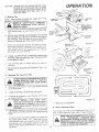
OPERA TtON
NEVER RUN THE ENGINE WITHOUT AIRINTAKE DUCT INSTALLED (FIG, 4). MAKE
SURE BOTTOM LIP OF AIR INTAKE DUCT
SITS BETWEEN BATTERY AND LIP OF
BATTERY TRAY.
WiTH
YOUR
THE
'THROTTLE
CONTROL
MOWER.
Use the runner on the R.H. side as a guide; the blade
cuts approximately
an inch outside
the runner (Fig.
t8).
b. Drive so that clippings are discharged onto the area
that has been cut. Have the cut area to the right of
the machine. This wit/ result in a more even distribution of clippings and more uniform cutting.
HEIGHT
ADJUSTMENT
KNOB
c . When mowing
large areas (Fig. 79), start by turning
to the right so that the chppings w/// discharge
away
from shrubs,
fences
driveways,
etc. After one or
two rounds, mow in the opposite direction
making
!eft hand turns until finished.
GEAR SHIFT
CONTROL
LEVER
FIGURE
17
FIGURE
t9
d. If grass is extremely taft, it should be mowed twice.
The first time cut relatively high; the second time
to the desired height.
e.
The left hand side of mower
trimming.
should
be used for
r, Do not mow tall, dry grass over 6 inches tall. It is a fire
hazard
5.
Operating
The Tractor
On Hills
f
DO NOT
DRJVE UP OR DOWN
NOT DRIVE ACROSS ANY
SLOPES GREATER
THAN
TO PAGE 5!.
_
a.
Move gear shift lever
up or down hills.
b.
A VOID
c,
tf slowing
to slower
STOPPING
OR SHIFTING
move
ENOUGH
l
starting
ON HILLS.
throttle
ROOM
]
SLOPE, REFER
!5':'
AND DO
to '" 1ST'" gear before
is necessary,
position.
LEAVE
HILLS WITH
control
WHEN
lever
STOP-
TRACTOR
DOWNHILL
AS CLUTCH/
PiNG AND ROLL
STARTING
TO ALLOW
SLIGHT
BRAKE PEDAL MOVES THROUGH CLUTCH
POSITION.
d.
tf stopping is absolutely
pedal quickly
to brake
brake.
, . To restart
tractor
necessary push ctutch/brake
position
and engage parking
movement,
make sure
tractor
Make
6.
Flip-Up
all turns
gradually.
Discharge
Guard
Your mower
has a flip-up discharge
door or gate clearance
when held
guard (Fig. 18,! for
in raised position.
MAKE SURE ATTACHMENT
CLUTCH LEVER
IS _N "DISENGAGED"
POS1T_ON
AND
BLADES HAVE STOPPED BEFORE RAIS{NG
DISCHARGE
GUARD {DEFLECTOR}.
NEVER
OPERATE MOWER W_THOUT
D_SCHARGE
GUARD _N OPERATING
POS_T_ON.
is in
the lowest
speed range (" 1ST'" Gear) and that you
have allowed room to roll stighdy downhill.
Depress
ctutch/brake
full. Disengaged
parking
brake and
rMease cJutch/brake
pedal SLOWLY
to start tractor
movemen:t.
f.
15
l
i
I
MAINTENANCE
With Every Mowing
1. Make sure a// nuts on bolts are tight and cotter
pins and retainer springs are secure.
2. Observe a// safety precautions.
3. Keep tractor we//lubricated
(refer to page 20).
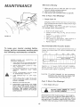
First
!.
2 Hours
Change
(Two
Engine
Mowings)
Oil
Changing off after the first two hours (or two mowings) will help eliminate break-in residue which might
be damaging
to your engine.
NOTE: BE CAREFUL NOT TO ALLOW DIRT TO ENTER
THE ENGINE WHEN CHANGING
OIL.
\
a. Drain oil with engine warm,
b Loosen oil drain wing nut (Fig, 20) and remove
dipstick.
c Catch oil m a suitable
container.
\
FIGURE
20
d
e
Tighten off drain wing nut.
Refill engine oil (See below).
1-1/2 quarts.
NOTE: DO NOT
Replace dipstick.
f
Recommended
To keep your tractor
running
better,
longer, perform
necessary
service using
the foflowing
maintenance
schedule:
_20 o
INSPECTION,
PUSH TRACTOR
CLUTCH/BRAKE
PEDAL
COMPLETELY
INTO BRAKE
.POSITION,
2.
MOVE
TRAL"
3.
PLACE
PARKING
BRAKE
POSITION,
REMOVE
PEDAL,
4,
PLACE
ATTACHMENT
CLUTCH
tN 'DISENGAGED'
POSITION,
5.
TURN
TION.
6_
MAKE
ABSOLUTELY
AND ALL MOVING
PLETELY
STOPPED,
7,
8,
REMOVE
IGNITION
THE
LEVERTO
KEY
SURE
PARTS
IGNITION
"NEU-
"'OFF"
I
0_
32 °
....
i
60 °
'
80 °
_
'
100 °
'
Capacity
is 1-1/2 quarts.
NOTE: DO NOT OVERFILL.
Dipstick assembly
must be securely
tightened
into tube
at all times when engine is operating.
IN "ENGAGED
FOOT
FROM
TO
Grades
AD_
t.
GEAR
SHIFT
POSITION,
Viscosity
is
Determine
temperature
range expected
before next oil
change. All oil must meet A. P. t. service classification
SD,
SE or SF.
....
BEFORE
MAKING
ANY
JUSTMENT
OR REPAIR:
SAE
Refill capacity
OVERFILL.
LEVER
CAUTION:
POSI-
TO AVOID DAMAGE TO THE STARTING
SYSTEM, USE SAE 5W30 OIL WHEN THE
TEM PERATURE FALLS BELOW 32 °.
THE BLADES
HAVE
COM-
Every
KEY,
DISCONNECT
THE SPARK PLUG WIRES
FROM
THE SPARK
PLUGS
AND
KEEP
AWAY
FROM
THE
SPARK
PLUGS
TO
PREVENT
INJURY
FROM
ACCIDENTAL
STARTING.
BE CAREFUL
TOO AVOID
TOUCHING
HOT ENGINE
OR MUFFLER
COMPONENTS.
t.
i
5 Hours
Check
_
Engine
(Five
Mowings)
Oil Level
WiTH
ENGINE
RUNNING.
DO NOT
CHECK
ENGINE
OiL LEVEL
Several minutes after stopping
engine, check engine c
level with tractor on level ground. Wipe dipstick
(Fig. 21)
clean, screw it down tight for a few seconds,
remove
and read oil tevef. If necessary,
add oil until "'FULL", mark
is reached, (See chart above), NOTE: DO NOT OVERFILL.
t6
1
Every
25 Hours
(Twice
a Mowing
tNTENANCE
Season)
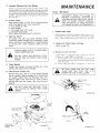
7. Brake Adjustment
This tractor
is equipped
with an adjustable
brake
system mounted
on the right side of the transaxle
(Fig. 22),
IF TRACTOR
REQUIRES MORE THAN
SiX FEET STOPPING
DISTANCE
IN
HIGHEST GEAR, THEN BRAKE MUST
BE ADJUSTED,
a.
Depress
brake,
clutch/brake
pedal
and engage
b.
Measure
and nut
distance
between
brake
"'A" on brake rod.
parking
operating
\
arm
\
ENGINE
OIL
DIPSTICK
AND
FiLL TUBE
c . If distance
is other than 1- !/2", loosen jam nut
(Fig. 22) and turn nut "A'" until distance
becomes
1-1/2".
Retighten
jam nut against
Nut "A",
Road test tractor
for proper stopping
stated above. Readjust
if necessary,
2,
distance
FIGURE
2 t
as
Tire Care
Maintain
tire pressure
at 12 PS!.
in front at I4 PSI and rear tires
Blade Sharpening
For best results mower blades must be kept sharp. The
blades can be sharpened with a few strokes of a file or
on a grinding wheel. We suggest they be sharpened
after every 25 hours of mowing. Do not attempt to
sharpen while on mower. If you mow in sandy soil
check the blades after each two mowings. The sand
wears the blades away rapidly,
a.
DISC
{WITH PARKING
BRAKE ENGAGED}
When grinding,
care should be taken to maintain
blade balance and the blade should be checked
for proper balance before remstaflation
on mower.
Unbalanced
or bent blade will cause excessive
vibration
when running,
and eventual
damage to
mower
or engine.
Replace
bent
or damaged
blades.
FIGURE
22
I
b_
L
To check blade balance, drive a nail into a beam
or watt. Leave about one inch of the straight nail
exposed. Place center hole of clean blade over the
head of the nail (Fig. 23). NOTE: CENTER HOLE
OF BLADE ON NAIL. IF BLADE iS PROPERLY
BALANCED,
BLADE SHOULD REMAIN IN POSITION SHOWN IN FIG. 23. IF EITHER END OF THE
BLADE MOVES
DOWNWARD,
BLADE tS NOT
BALANCED.
SHARPEN THE HEAVY END UNTIL
BLADE tS BALANCED.
i
E
CENTER
FIGURE
17
23
INTENANCE
Every
50 Hours
(Operating
servicing,)
{Once
in dusty conditions
a Mowing
Season)
may require
more frequent
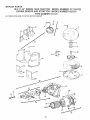
CUT AWAY VIEW
b
1. Check Battery
a. Battery
acid
level
in each
battery
cell
should be even with bottoms of tubes in cells (Fig.
24), Add ONLY distilled
water
if necessary,
NOTE: DO NOT OVERFILL,
VENT CAP
_m
BATTERY
TUBE
b.
c.
d.
BATTERY
CELL
e.
FIGURE
2.
24
_,_
Keep battery
and terminals
clean.
Keep battery
bolts tight.
Keep vent caps tight and small vent holes in caps
open,
Recharge at 6 amperes for t hour if necessary,
Clean
Battery
and Terminals
Corrosion and dirt on the battery
battery
to "leak"
power,
KNOB
LEAD-ACID
and terminals
BATTERIES
GENERATE
cause the
EX-
PLOSIVE
GASES.
KEEP
SPARKS,
FLAME
AND SMOKING
MATERIALS
AWAY
FROM
BATTERIES.
ALWAYS
SHIELD
YOUR EYES
AROUND
BATTERIES.
CARTRIDGE
PLATE
a,
b.
PAPER
CARTR1DG[
-..,.
d
FOAM
PRE CLEANER
e
f.
\
g,
Remove
terminal guard.
Disconnect
BLACK battery
cable then RED battery cable and remove
battery
from tractor.
Wash battery
with four tablespoons
of baking
soda to one gallon of water. NOTE: BE CAREFUL
NOT TO GET THE SODA SOLUTION
INTO TH
CELLS,
Rinse the battery
with
plain
water,
dry and
reinstall on tractor.
Clean terminals and battery cable ends with wife
brush until bright.
Replace battery cables, connecting
RED battery
cable to positive terminal
first, then BLACK battery cable to negative terminal. Coat terminal connections
with Vasofine,
Replace
terminal
guard.
BODY
3.
FIGURE
Engine Oil
The best time to change engine oil is at ":he end of
a day's operation
when all dirt and foreign materials
are suspended
in the hot oil. See chart, page !6,
25
\
Change
GREASE
BOTH
(OPERATING
IN DUSTY CONDITIONS
MORE FREQUENT
SERVICING)
MAY
REQUIRE
_ WHEE
4.
O
tt
II
OIL
SPINDLES
FBGURE 26
18
Clean Air Cleaner Foam Pre-Cfeaner
(Fig. 25)
a, Remove Knob and cover,
b. Remove foam pre-cleaner
element
by sliding it
off of the paper cartridge.
c, Wash foam pre-cleaner
in liquid detergent
and
water,
d. Wrap foam pre-cleaner
in cloth
and squeeze
dry,
e. Lightly coat foam pre-cfeaner
with engine o
(Do not saturate).
Squeeze in rag or towel to
remove excess oil.
f. Install
foam pre-cleaner
over paper
cartridge.
Reassemble
cover and screw down tight,
5.
Lubricato
Steering
And Front
INTENANCE
Wheels
There is a grease fitting on each front wheel
Use
a grease gun to give each grease fitting two shots
of extreme press ure lubricating
grease A mdex No. 1
or equivalent
[available through your Sears Service
Center).
Use 30 weight oil to lubricate
front spindles (Fig. 26).
Every
100
DISCONNECT
PREVENT
FORE
MENT
6. Oil Pivot Points
Place several drops of SAE 30 oil at points where
parts move against each o ther, especially:
a. Front wheel spindles.
b. Hood hinges.
c. Foot peda/ shaft (both ends).
d. Lift shaft (both ends).
SEE L UBRtCA T/ON CHART, PAGE 20.
TOR).
HOT
!,
Air screen (Fig.
to prevent engine
with a wire brush,
to remove dirt,
fibers.
ALWAYS
DO
WEAR
NOT
DER
25) must allow free-flow of air
damage from overheating. Clean
compressed air or water pressure
chaff, stubborn
dried gum and
SAFETY
COMPRESSED
OR
TOUCH
FINS
GLASSES
AS CONTACT
CAUSE
BURNS,
8,
Check Muffler
inspect and replace corroded muffler
create a fire hazard and/or damage.
9. Clean Engine
DER
OR
TOUCH
FINS
HOT
AS
TO AVOID
TOUCHING
OR MUFFLER
COMPONENTS,
Plugs
Replace
in-Line
Fuel Filter
7
MUFFLER,
CONTACT
BE CAREFUL
BE SURE THERE ARE NO FUEL LINE|
LEAKS
AND
THAT
FUEL
LINE
IS IN
PROPER POSITION 1N HOSE CLAMPS,
Cooling Fins
NOT
ADJUST_
CARBURE-
as it could
Remove any dust, dirt or off from engine cooling
fins to prevent engine damage from overheating,
Air guide covers must be removed (F_g. 27).
Remove eight 7/16" bolts and six 5/!6" bolts to
remove side and top covers. See hood removal
page 23.
DO
INSPECTION,
(EXCEPT
If fuel filter is clogged,
obstructing
fuel flow to
carburetor,
replacement
is required.
a. With engine
cool, remove
filter
and plug fuel
line sections
as removed from both ends of fuel
filter fFig, 29),
b, Place new fuel filter in positron
in fuel line.
CYLIN-
MAY
TO
BE-
WHEN
3.
MUFFLER,
WIRES
STARTING
MAKING
ANY
OR
REPAIR
ENGINE
Spark
PLUG
2. Replace Air Cleaner Paper Cartridge
Refer to page 18.
AIR.
HOT
Replace
SPARK
ACCtDENTAL
Replace spark plugs at the beginning
of each mow,,
ing season or every 100 hours, whichever
comes
first,
Gap should
be set at 0.030
inch (Fig 28L
7, Clean Air Screen
USING
Hours
MAY
.030"FEELER
GAUGE
CYLiNCAUSE
PLUG
BURNS.
FIGURE
28
\
MUFFLER
F_GURE 27
;_VGURZ:29
t9
INTENANCE
Lubrication
Chart
SPINDLE
_
WHEEL
BEARINGS
_WHEEL
BEARINGS
(2"t
'NE_
CLUTCH
BOTH
_.
SAE MOTOR
_
EXTREME
PRESSURE
LUBRICATING
GREASE
_,
REFER
TO ENGINE
OIL SPEC'S.
(UNDER
INITIAL
PREPARATION
IN OWNERS
MANUAL)
PIVOT(_
ENDS
LIFT
SHAFT
_
OIL
REPAIR & ADJUSTMENT
FOR
ANY
ADJUSTMENTS,
OR MAINTENANCE:
NEGATIVE
(BLACK
CABLEt
INSPECTION
TERMINAL
1,
2.
iRY
3.
20
SHIFT LEVER
TO "NEUTRAL"
PLACE PARKING BRAKE IN '*ENGAGED
SIT.ION. REMOVE FOOT FROM PEDAL.
PLACE ATTACHMENT
CLUTCH
'DISENGAGED'
POSITION,
5.
TURN
6,
MAKE ABSOLUTELY
AND ALL
MOVING
PLETELY STOPPED,
8.
FIGURE 30
MOVE GEAR
POSITION.
4.
7,
POSITIVE
_REDCABLE!
TERMINAL
PUSH TRACTOR
CLUTCH/BRAKE
PEDAL
COMPLETELY
INTO BRAKE POSITFON,
IGNITION
REMOVE
THE
KEY TO
"OFF"
SURE
PARTS
_GNITION
PO-
LEVER
IN
POSITION.
THE BLADES
HAVE
COM-
KEY.
DISCONNECT
THE SPARK
PLUG
WIRES
FROM
THE SPARK PLUGS AND KEEP AWAY
FROM THE SPARK PLUGS TO PREVENT INJURY FROM ACCIDENTAL
STARTING,
BE
CAREFUL TOO AVOID TOUCHING
HOT EN
GtNE OR MUFFLER COMPONENTS.
REPAIR
& ADJUSTMENT
1, Starting
your
Tractor
With
a Weak
Battery
If your battery is too weak to start the engine, it should
be recharged.
If "jumper
cables'" are used for emergency starting,
follow this procedure:
NOTE: YOUR TRACTOR IS EQUIPPED WITH A 12 VOLT
NEGATIVE GROUNDED SYSTEM. THE OTHER VEHICLE
MUST ALSO BE A 12 VOLT NEGATIVE
GROUNDED
SYSTEM,
iDLE SPEED
SCREW
MIXTURE
VALVE
GOVERNOR
LEVER
FIGURE
LEAD-ACID
BATTERIES
GENERATE
EXPLOSIVE GASES. KEEP SPARKS, FLAME
AND
SMOKING
MATERIALS
AWAY
FROM
BATTERIES.
ALWAYS
WEAR
EYE PROTECTION
WHEN
AROUND
BATTERIES.
CONTROL
3 !
a_
b,
C,
d,
SPARK
PLUG
CARBURET(
Connect
each end of the RED cable to the
POSITIVE
(+) terminals
of each battery
_taking
care not to short against
chassis)
(Fig, 30).
Connect
one end of the BLACK
cable to the
NEGATIVE ( - ) terminals of fully charged battery.
Connect the other end of the cable to the L.H. side
panel bolt (Fig. 16), NOTE: KEEP AWAY
FROM
GAS TANK AND BATTERY,
Disconnect
cables in reverse order:
1, L.H, Side Panel Bott (Fig 16),
2, Negative
terminals
of fully charged
battery.
3. Positive terminals.
DO NOT USE YOUR TRACTOR BATTERY TO START OTHER VEHICLES.
SPARK
PLUG
I
_
J
2,
CARBURETOR
Throttle
Control
Cable
Adjustment
/Vever attempt to change maximum engine speed,
This is preset at the factory (3600 z 100 RPM)
and should on/f/be changed by a qualified service
technician who has the necessary equipment,
a. Remove hood (page 23).
b. Loosen casing clamp screw until throtde came
is free to move.
c, Move throttle control
(on the dashboard) to
"FA S T'" position,
d. Put! throttle
came tight (until swivel
below
carburetor
is against side of quarter circle).
Retighten
casing clamp screw.
_
FIGURE 32
21
PAGE
REFER 13. TO
"STARTING
THE
ENGINE,"
REPAIR & ADJUSTMENT
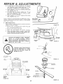
3,
Carbureter
BELT
GUIDE
Adjustment
\
TRANSAXLE
PULLEY
NOTE:
ADJUST
THROTTLE
CONTROL
CABLE
BEFORE
MAKING
ANY
ADJUSTMENT
TO
CARBURETOR.
AIR CLEANER
MUST BE ASSEMBLED
TO
CARBURETOR
WHEN
RUNNING
ENGINE.
Minor carburetor adjustments may be required to
compensate
for differences in fuel, temperature
or altitude.
Adjust
the carburetor
fuel mixture
as fotlo ws:
a. Gently
turn idle mixture
valve clockwise
(_
) (Fig. 32) until it just doses and then
counterclockwise
(_
) 1-1/2 turns.
CAUTION:
Valve may be damaged if turned
in too far.
b, Start
engine and allow
to warm for five
minutes. Make final adjustments with engine
running and choke pushed in.
c. Move throttle control lever (on dashboard) to
"'SL 0 W'" position,
d. Hold governor control lever against idte speed
screw, and adjust idle speed screw to obtain
!200 to 1400 RPM (Fig. 31),
e. While still holding the governor control lever
against idle speed screw, turn idle mixture
valve slowly
clockwise
f_)
f/can mixture)
until speed just starts to slow.
f. Turn idle mixture valve back to the midpoint
between rich and lean.
g. Adjust the idle speed screw to obtain 900 to
1200 RPM. Release governor control lever.
h. Move throttle control
(on the dashboard) to
"'FAST. "" /f engine hesitates or dies, turn idle
mixture valve approximately
1/8 rum counterclockwise
(_'_-) until engine will accelerate
as throttle
control
is moved from "'SLOW'"
to "'FAST. ""
RETAINER
SPRING
BELT GUIDE
BRACKET
RETAINER
SPRING
FIGURE
33
ENGINE
PULLEY
R.H. SIDE
DRIVE
BELT
SCHEMATIC
CLUTCH
PULLEY
L.H. SIDE
4. Motion Drive Belt Replacement
BELT
The tractor drl've belt may be rept!aced without
tools. Park the tractor on l_v_, area. Engage
parking brake,
NOTE: BELT _NSTALLATION DECAL UNDER LEFT
FOOTREST.
a, Remove mower (page 23),
b, Remove two retainer springs from belt guide
bracket
betow
transaxle
pufley.
Remove
bracket (Fig, 33).
c, Swing belt guides away from be/t, toward rear
of tractor (Fig, 33).
d. Roll belt over top of transaxle pulley,
e. Rot/ belt over engine pulley and off idler
(Fig. 34),
f. Release parking
brake. Pull belt as far as
possible over top of clutch pulley.
g. Reset parking
brake. Pull belt over top of
clutch pulley (Fig. 34).
h. PuP belt out through shift gate to remove
from tractor (Fig. 35).
Install belt by reversing above procedure.
NOTE: REPLACE ONLY WITH BELT LISTED tN
MANUAL,
\
-F_EAR
VIEWED
of fuse is directly
FROM BOTTOM
OF TRACTOR
FIGURE
BELT
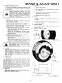
5, Fuse Replacement
Replace with 30 amp automotive-type plug-in fuse.
Fuses can be purchased at all Sears Service Centers
and most
retail stores. Locatbn
behind
dash.
GUIDE
22
_"k_
34
REPAIR & ADJUSTMENT
6.
Hood Removal
a . Lift hood, Disconnect
headlight
wiring connection
(Fig, 37).
b. Unscrew one screw at rear of each side panel (Fig.
36),
c, Pivot hood and side panel forward
and lift off tractor (Fig. 37).
d. To replace,
reverse the above procedure.
7, Mower
Removal
a,
Remove
mower
belt per instructions
under
"Mower
Drive Belt Removal'"
through
step fd,t.
b, Remove
retainer
spring
from
clutch
rod; pu//
clutch rod out of clutch bracket
(Fig, 38)
c, Puff retainer
springs
out of rear suspension
trunnions.
Remove
rear suspension
trunnions
from l/it brackets
(Fig, 38).
d, Pull
retainer
spring
out of rear hinge pin.
Remove rear hinge pin,
e, Pull retainer
spring
out of front
hinge pin,
Remove front hinge pin (Fig, 38/.
f. Use /fit
lever to raise suspension
arrr, s, Slide
mower
out from under tractor,
NOTE: IF AN ATTACHMENT
OTHER THAN THE MOWER
DECK IS TO BE MOUNTED ON THE TRACTOR, THE L.H.
AND R.H, SUSPENSION ARMS {FIG. 38t SHOULD
BE
REMOVED FROM TRACTOR.
SCREW
FIGURE
36
,
Housing
Side-to-Side Mower Adjustment
a. Depress rift lever plunger and use/fit lever to
raise mower to maximum cutting height,
b. Measure height from bottom of cur/to ground
level at front of mower. Distance "A "" should
be the same (Fig. 39).
c. If distance "'A "" needs to be changed, snap out
access hole cover on L.H, side above footrest.
Use 11/16" wrench on nuts "B" and "'C'" at
side-to-side adjustment trunnion (Fig, 40).
d. To raise left side of mower, loosen nut "B'"
and tighten nut "'C':
e. To lower left side of mower, loosen nut "'C'"
and tighten nut "'B':
NOTE: ONE ROTATION OF ADJUSTMENT NUTS
tS EQUIVALENT
TO APPROXIMATELY
3/16"
HEIGHT CHANGE.
f. Be sure all nuts are securely tightened.
FIGURE 37
_,
\
RETAINER
SPRING
R,H.
SUSPENSION
RETAINER
SPRINGS
MOWER
PARALLEL
LINK
_eURE 38
Mower
Adjust
the mower
while tractor
is parked on feve/
ground or driveway.
Make sure tire pressures are 14
PSi in front tires and 12 PSI in rear tires. If tires are
over or under inflated,
you will not properly
adjust
your mower,
WIRE
CONNECTION
t
RETAINER
SPRING
Level
CLUTCH
Front-To-Rear Mower Adjustment
a. To obtain the best cutting results, your mower
housing should be adjusted so the front and rear
flange distance "D'" (Fig. 41) is 1/2" lower in
front when the mower is positioned in the highest
cutting position° NOTE: MEASURE DISTANCE
"D" FROM GROUND LEVEL TO BOTTOM OF
CURL ON RIGHT REAR FLANGE AND COMPARE
TO D_STANCE "D" AT R!GHT FRONT FLANGE.
ROD
23
REPAIR & A DJUS TMEN TS
b.
To raise rear of mower, loosen nut "E" on borh
rear suspension
arms, Screw both nuts "F" up
an EQUAL
NUMBER
OF TURNS
(Fig. 42),
c. When distance
"'D" is !/2"" /ower at front than
rear, tighten nuts "E"
d, To lower
rear of mower,
loosen
nut "F" on
both
rear suspension
arms an EQUAL
NUMBER OF TURNS
(Fig, 42),
e, When distance
"D" is 1/2"" lower at front than
rear, retighten
nuts "E':
NOTE: WHEN ADJUSTING
NIONS, ALWAYS
ADJUST
WILL STAY LEVEL.
.
REAR SUSPENSION
TRUNBOTH EQUALLY SO MOWER
Blade Replacement
Raise mower to highest position
blades or remove mower,
a,
b.
c,
d,
to permit
Remove bolt, fockwasher
and washer
(turn counterclockwise)(_'_
).
Remove
and discard old blade.
Clean
top
Place new
sharp edge
washer and
access
to
FIGURE
40
(Fig. 43)
/
and bottom
of mower
housing,
blade between
flanges, (Install with
down), and secure with washer, lockbolt previously removed.
FLANGE
\
ALWAYS
USE GRADE 5 HEAT TREATED
BOLTS
TO ATTACH
BLADES.
CHECK
BOLTS tN BLADES
OCCASIONALLY
TO
MAKE SURE BOLTS ARE TIGHT. TORQUE
BOLTS 30 - 35 FT- LBS.
D
BOTTOM
OF CURL
GROUND_"T
LEVEL
FIGURE 41
A GRADE 5 HEAT TREATED BOLT
CAN BE IDENTIFIED
BY THREE
UNES ON THE BOLT HEAD AS
SHOWN AT LEFT.
L_FT
LEVER_
PLUNGER
_/
[.EVER
BOTTOM
__
OF CURL ,
i
_
._
iBOTTOM
OF CURL
)
BLADE
___
L_KWAS.E.
------"-'.@
.,×,o_,.
s---_
GROUND
LEVEL
FIGURE 39
_
"-,._
FtGURE 43
24
REPA
& ADJUSTMENT
, C.
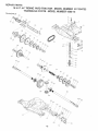
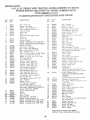
10. Rear Wheel Replacement
Coat axle with grease to prevent corrosion or rust
accumulation
and eventual seizing of wheel hub
to axle shaft.
2. Pour one ounce of oil through spark plug holes
into cylinders.
WHEN
REPLACING
WHEELS
ON THE
TRACTOR
THEY
MUST
BE MOUNTED
WITH THE LONG HUB SIDE TOWARD THE
CENTER
OF THE TRACTOR.
INCORRECT
INSTALLATION
COULD AFFECT LATERAL
STABILITY.
(SEE FIG. 46),
! 1.
3. Turn ignition key to "START"
few seconds to distribute oil
D,
a. Maintain tire pressure of 14 PSI in front tires
and !2 PSI in rear dres.
b. Keep tires free of gasofine, oi/or insect contro/ chemicals
which can harm rubber.
c. Avoid stumps,
stones, deep ruts and other
hazards that may cause tire damage.
(t. Removing front wheel for tire repair (Fig. 44):
--- Block up front axle securely.
---Remove
hub cap, k/ip ring and washer to
allow wheel remova/.
---Repair
tire and reassemble. Replace washer
and snap k/ip ring securely in axle groove.
Replace hub cap.
e. Removing rear wheel for tire repair (Fig. 45):
--. Block up rear axle securely.
---Remove hub cap, E-ring and washer to allow
wheel removal
--- Repair tire and reassemble. While maintaining
key position,
replace washer and snap E-ring
securely in axle groove. Replace hub cap.
clean
terminals
2. After a period of time in storage,
require recharging.
E.
for a
and top
battery
of
may
General Cleaning
Clean engine, battery,
seat,
foreign matter,
F. Store in a Clean Dr}! Area
finish,
etc.
of
a//
©
WASHER
HUB
CAP
FIGURE
44
CAN
BEADS
I2.
Storage
Remove mower from tractor for winter storage.
When mower is to be stored for a period of time,
clean it thoroughly,
remove all dirt, grease, leaves,
etc. Give blades and underside of housing a good
coat of grease or rust preventative.
Store in a
clean dry area.
A.
Fuel System
IT tS IMPORTANT
TO PREVENT
GUM DEPOSITS
FROM
FORMING
IN ESSENTIAL
FUEL SYSTEM
PARTS
SUCH AS
THE CARBURETOR,
FUEL FILTER,
FUEL HOSE.
OR TANK
DURING STORAGE.
ALSO.
EXPERIENCE
INDICATES
THAT
ALCOHOL
BLENDED
FUELS
_CALLED
GASOHOL)OR
USING
ETHANOL
OR METHANOL
CAN ATTRACT
MOISTURE
WHICH
LEADS TO SEPARATION
AND FORMA TION OF ACIDS DURING
STORAGE.
ACIDIC
GAS CAN DAMAGE
THE FUEL
SYSTEM
OF AN ENGINE
WHILE
IN STORAGE,TO
AVOID
ENGINE
PROBLEMS,
THE FUEL SYSTEM
SHOULD BE EMPTIED
BEFORE STORAGE
FOR 30 DAYS OR LONGER,
B.
position
4. Replace with new spark plugs.
Battery
1. Prior to storage,
battery'.
Tire Care
ARE
SEATED,
OVER
INFLATION
WHEN
MOUNTING
TIRES,
UNLESS
CAUSE
AN EXPLOSION.
Cylinders
i. Remove spark plugs.
E-RING
/
HUBCAP
FIGURE 45
Eng#_ Oil
Drain (with engine warm) and replace with clean
engine eiL (See chaR, page t6),
\
"-__.-._
25
LONG
HUB
FIGURE
46
TROUBLESHOOTING
PROBLEM
WILL
WiLL
NOT
NOT
ENGINE
HARD
CAUSE
CLICKS
(SEE INDEX)
Push Ctutch/Brake
Pedal into brake position
Charge or replace Battery
Move Attachment
Clutch Lever to "'D/SENGAGED"
Replace Ignition Switch
Replace Interlock
Switch(es)
Replace Solenoid
or Starter
Replace Spark P/ugfs)
Replace Fuse
Cheek a// Wire Connections
and "'Ground'"
Points
Rea ttach Tiller A ttachmen t Wire Loop
OVER
BUT WON'T
Clean Battery
Terminals
Replace Starter or Solenoid
Charge or Replace Battery
Check Wire Connections
and
START
"Ground'"
Points
Place Throttle
Control in "'FA S T'" position
and run
starter several times to clear out gas
Remove Air Filter and clean
Replace Spark P/ug(M and adjust gap
Recharqe or replace Battery
Check the Wiring
Drain Fuel Tank and Carburetor.
Use Fresh Fuel.
Replace Fuel Filter
Make necessary adjustments
to Carburetor
Major Engine Overhaul
TO START
Shift to a lower gear or reduce load
Drain Gas Tank and Carburetor.
Use Fresh
Remove and clean Air Cleaner
ENGmNE MISSES
OR LACKS
or reduce
load
Add or change oil
Clean Engine Cooling Fins
Remove and clean Muffler
or replace
Remove and clean Air Filter
OVERHEATS
Use fresh
fuel and adjust
Carburetor
NO LIGHTS
Check Fuse, Switch
Head/ight
Bulbs
Replace Switch
WON'T
Check Fuse for fault and replace
Replace Battery
Replace Diode Assembly
Replace Alternator
CHARGE
OPERATOR
PRESENCE
DOWN
ENGINE
WHEN
Fuel
Make necessary carburetor
adjustments
Clean Air Screen
Add or change oil
Replace Spark Plug(s) and adjust gap
Replace Fuel Filter
Major Engine Overhaul
POWER
Shift to/owergear
Clean Air Screen
ENGINE
1
Fi// Tank with Gasoline. Check Fuel Line and Carburetor
(clean if necessary),
Replace Fuel Filter,
Use Fresh Fuel
Recharge or replace Battery
Check Wiring
Replace Spark Plug(s) and adjust gap
Drain and replace o//for
proper temperature
START
TURN
/ REMEDY
SYSTEM
OPERATOR
WILL NOT
LEAVES
SHUT
SEAT
and Wire Connections,
Engage Attachment
Clutch
Check all Wire Connections
Check Seat Switch
NOTE: This tractor is equipped with an operator presence
sensing system, Any attempt by the operator to leave the seat
with the engine running and the attachment clutch engaged
wil! shut down the engine,
26
Replace
position
TROUBLESHOOTING
Move Throttle Control to
"FAST_
UNSATISFACTORY
MOWER PERFORMANCE
UNEVEN DISTRIBUTION
OF CLIPPINGS
Check air pressure in Tires
Check front-toorear
and side-to_side Mower
Use a slower ground speed
Replace Mower Blades
Reinstall Mower Blades with Top of Blade
Clean underside of Mower Deck
Readjust Mower Drive Belt
MOWER
Correct Clutch Mechanisrn
Interference
tnsta/l new Mower Drive Belt
Reinstall Mo wet Drive Belt
Ad/ust Mower Drive Belt
Replace frozen Mandrel
Replace frozen Idler Pulley
BLADES
EXCESSIVE
W_LL NOT ROTATE
MOWER
WiND ROWING STR_PPING
OF GRASS CLIPPINGS
UNEVEN
CUT
Replace
Replace
V_BRATgON
bent or unbalanced
Mandrel
Straighten
adjustment
up
Blades
Deck or replace
Set Throttle
for maximum
engine speed
Let .grass dry out
Clean underside
of Mower Deck
Readjust Mower front.to-rear
and side-to-side
Replace Blades
OR DROPPING
Readjust Mower front-to-rear
Replace Blades
Replace bent Mandrel(s)
OR SCALPING
and side-to_side
SERWCE
RECORD
SCHEDULE
SERVICE
RECORD
Filf in dates
as you
complete
.requiar_ serwce
F,RSY!VERY EVERY
2
_
HOURS
5
HOURS
i HOURS
[
..............
[
X
m
Engine
CIean
Air
Oil
i,
J
! ×
/
1
1
i
[
Muffler
Screen and
Engine
Front
l
Cooling
f
!
,,
×
!.........
×
Fins
i
i × i
t'.........................
Clean
]
×
Oil Levet
Filter
Clean Air
i
× i
X
.................
Check
,,_,.
i
Engine
Check
i
!
t ..............
Battery
Change
L
HOURS
I
*
Check
i EVERY_'
1
200
HOURSI
X
......
Adjustment
i EVERY
100
HOURS
l,
,,! .........
Blades
Brake
EVERY
50
25
Gritf
.............
Lubricate
Replace
Spark
Reptace
Air
×
Plugs
Filter
X
Cartridge
Fuei Filter
i
......
Sears, Roebuck and Co. reserves the right to make any changes in design or
improvements
without imposing any obligation to instal/the
same upon its
terms heretofore
_
.......
i
x
Tires
t
]
X
Tractor
manufactured.
27
X
....
i
_
1
28
18 H. P. 44" RIDING YARD TRACTOR
- MODEL
NUMBER
917.254722
SCHEMATIC
RED
+
12V
f
l
RED
RED
WIRE
LOOP
.',TE
WHITE
I
MC;
AMMETER
IGNITION
SWITCH
30 AMP
GQ
L
c_
iGNITION
SWITCH
70-S,TTON
CIRCUIT
OFF
M-G
ON
B-L
DIODE
.......
START
RED
WHITE
3 AMPS DC
AT 3600 RPM,
B-S
___.../_._/_._,__j
_
BATTERY
CHARGING
CO_L
20 VOLTS
IN LINE
AC (MIN)
AC COiL
ORANGE
......................
14VOLTSAC
(MIN) I
LIGHTS OFF AT
3600
RPM
q
/
BROWN
_}_/O
LIGHT
SWITCH
WIRING
YOUR TRACTOR IS EQUIPPED WITH A
SPECIAL ALTERNATOR
SYSTEM. THE
LIGHTS ARE NOT CONNECTED TO THE
BATTERY,
BUT HAVE THEIR OWN
ELECTRICAL
SOURCE, BECAUSE OF
THIS,
THE
BRIGHTNESS
OF THE
LIGHTS
WILL
CHANGE
WITH THE
ENGINE SPEED_ AT IDLE SPEED THE
LIGHTS WILL DiM. AS THE ENGINE IS
SPEEDED
UP, THE LIGHTS
WILL
BECOME THEIR BRIGHTEST.
NOTE:
WERE
INSULATED
IF WIRING
REMOVED
INSULATED
CLIPS
FOR SERVICING
OF
UNIT, THEY SHOULD
PROPERLY
SECURE
BE REPLACED
YOUR WIRING.
NON-REMOVABLE
CONNECTIONS
REMOVABLE
29
CLIPS
CONNECTIONS
TO
/
CHASSIS
GROUND
REPAIR
PARTS
18 H. P. 44" RIDING YARD TRACTOR
ELECTR
- MODEL NUMBER
917.254722
iCAL
18
36
r
45
o
15
38
19
3
/
7
24
33
REPAIR
PARTS
18 H. P. 44" RIDING YARD TRACTOR
- r,AODEL NUMBER
917.254722
ELECTRICAL
KEY
NO,
PART
NO.
DESCRIPTION
1
2
3
4
5
6
7
8
9
I0
!2
13
14
15
16
17
18
19
20
21
22
23
24
109310X
110859)(
Molded Key
Harness, Light
4152J
STD365402
109553X
Bulb - Light
Switch _ Ignition
Switch,
Interlock
109788X
110712X
.!09081X
10090400
Ignition,
Nut
Switch - Light
Solenoid
WasherLock
STD541225
11050400
Socket
- Attachment
Clutch
1/4
*Nut - Jam 1/4 - 20
WasherLock - Ext.
KEY
NO.
PART
NO,
25
26
STD522507
STD551025
27
28
29
STD551 t25
STD541025
STD541625
3t
32
33
34
t02476X
72240460
I2t433X
74641008
DESCRIPTION
*Bolt
_Nut
*Nut
I/4
- 20x
3/4
x 16 Ga.
- Hex !/4 - 20
- Wing 1/4 - 20
Guard..
Terminal
Bolt.
Rd, Hd. Sq. Nk, 1/4 -20 x 7-t/2
Ammeter
Screw- Slotted Pan Head
910
Tooth
- Hex
*Washer 9_2 x 5/8
*WasherLock !/4
- 32x
1/2
1/4
73510400
719J
Nut, Keps 1/4 - 20
CoverTerminal
36
37
t0250IX
73951000
121434X
4799J
4206J
4207J
Harness - Ignition
Cable.
Battery
CaMe _ Battery
Cable - Ground
38
39
40
41
235R
STD522505
73680400
100541K
t09787X
I2 I537X
121305X
1044452(
BezelIgnition
Battery
Seat - Plunger
Switch .. Interlock-
42
43
44
45
109596X
4 t 7t R
I21264X
t2165tX
17021008
108824X
Screw-Hex
Tap_ I0-24
Fuse - 30 Amp
--_--
101539)(
124450X
Clutch
x t/2
Wire Loop
Nut - Keps
B
C
E
_10
@12
_
13
._40
_37
- 32
C/am_ _ Hose
Clip.
Insulated
Caps, Battery
Decal, Sears
Sheet
- Instruction,
Tractor
15 ° Slope
Owner's Manual
S TA NDA RD HA RDWA
A
910
Clip- Insulation
*Bolt.
Hex !/4 - 20 x I/2
Nut - Crown/ock
t/4 - 20
Tube
RE--PURCHA
SE L OCA L L Y
REPAIR
PARTS
t8 H. P. 44" RIDnNG YARD TRACTOR
CHASSIS
AND
° MODEL NUMBER
ENCLOSURES
91
95
98
\
8O
i
10
!9
94
68
47
43
48
C
72
44
38
73
42
7_
32
917.254722
REPAIR PARTS
18 H. P. 44" RiDiNG
CHASSIS
KEY
NO,
AND
YARD TRACTOR
- rvIODEL NUMBER
917.254722
ENCLOSURES
PART
NO.
DESCRIPTION
KEY
NO,
PART
NO,
DESCRIPTION
I20039X
121247)(
105513X
t05529X
Seat
Pan - Seat
Bracket. Pivot - Seat
Bolt., Shou/der 5/16 - 18
5
6
7
8
9
10
1210932(
73680500
73680600
12t642X36I
106202X
t05801X
Cap - Spring
Nut- Lock 5/16_ 18
Nut _ Lock 3/8- 16
Fender
Reflector.
Rear
Decal
50
52
54
55
5 6
5 7
58
59
106013X0t8
73680400
t08067X
t05528X
105806X
105568X
12 I248X
t21249X
Hood
Nut - Crowntock
Par - Nut
Grill
Decal - Grill
Decal - Stripe
Bushing,
Snap
Spacer, Split
1t
17490612
60
6 1
62
121250X
t 08403X
I08470X
Spring, Compression
Panel - Side - R.H.
Panel
Side . L,H,
12
I3
14
I5
16
t7
I8
t9
20
2t
19131312
STD523707
105551X
19171912
STD551150
t08885X
t21246X
121067x
13553 tX
105509X
63
64
66
6 7
106091X
t06090X
706003X
106004X
Hinge - R.H,
Hinge - L.H.
Lens . R.H.
Lens - L.H.
68
70
72
72
73
74
75
76
77
78
79
80
81
82
110897X
108512X
108513X
4900J
109199X
STD523710
8710J
110350X
STD522505
235R
11050600
106813X
106814X
106974X
83
t 7490612
84
85
19131616
19131614
87
88
89
90
91
92
93
94
95
96
97
98
106909X
1069102(
I08402X
121251X
721704 !0
74780816
121144X
5320R
73900400
74641008
73951000
4171R
!
2
3
4
Screw, Flex Washer Thd. Rol!
3/8-16 x 3/4
Washer 13/32 x 13/16 x I2 Ga.
*Bolt, Hex, 3/8-16 x 3/4
Strap - Fender
Washer 17/32x
13/16x
12 Ga,
*Wasl?er. Lock !/2
Guard- Muffler
Bracket, Switch - Seat
Compression
- Spring R.H.
Nut, Push
BracketFender
23
t06020X
Tank - Fuel
24
25
26
t21221X
6999R
5277J
Cap- Fuel
Clamp - Hose
Line - Fuel
27
28
29
30
106082X
I21277X
121306X
105523X
Pad. Spacer
Chassis Assembly
Dra wbar
Panel. Dash - L,H.
31
121794X
Cover, Access
32
tI0828X
Panel.
33
35
36
t05525X
105465){
105464X
Bracket. SupportFootrest - L.H.
Footrest. R,H,
37
38
39
STD533707
t05466X
1 t0923X
40
41
42
4 3
4 4
4 5
4 6
4 7
48
49
3645J
105566X
275 t R
I t0436X
105839X
105838X
10575 IX
105867X
109015X
!090!6X
Dash oR.H.
Bezel. Headfigh t
Bracket - Pivot - R.H,
Bracket - Pivot _ L.H.
Decal, Clutch/Brake
Decal. Drive Be!t
*BoltHex 3/8-16 x 1
Stem - Tank, Fuel
Strap Assembly.
Grill
Bolt - Hex !/4 . 20 _ 1/2
Clip. Insulated
Washer, Lock, Ext, Tooth 3/8
Decal. Stripe, Side Panel, L,H.
Decal • Stripe, Side Panel, R,H,
Decal.
Caudon
BoJt, Hex Washer T.hread Ro/t/ny
3/8.16
x 3/4
Washer 13/32 x I x 16 Ga,
Washer - t3/32
x I x t4 Ga
Dash
*Bolt, Cart'. 3/8-16x
3/4
Pad, Footrest
Br_ket.
Clutch _Mower
Bushing
Decal. 5 Speed- 44"
Clip _ Insulated
Grommet
Receptacle
Retainer
Stud - l/4 Turn
Shield - Heat
Bracket.
Pivot.
L.H,
Bracket - Pivot - R.H.
Screw. Special
Screw- Spec/a/
U.Clip
Strip, Foam
Bolt, Cart. l/4 - 20 x t- 1/4
Bolt 1/2.13x
l
Shoulder Bolt
Clip. Insulated
Nut, Hex 1/4- 20
Screw - S/td, Pan Head #I0 - 24 x I/4
Nut, Keps #10- 24
Clip, Insulated
*STANDARD
A
B
C
'_4
H
11
,,
U
U
_7
_74
_
@!2
_97
J
K
HARDWARE-PURCHASE
L
N
P
0
LOCAL
LY
T
S
13
G_2
V
t/4-20
U 87
_,88
52
_7
_se
@ 12
,8_79
®7
96
33
7
3
@84
REPAIR PARTS
t8 H. P, 44" RIDING YARD TRACTOR
,. MODEL NUMBER
DRI_VE
3
32
32
85
12
9! 7.254722
REPAIR
PARTS
18 H° P. 44" RIDING YARD TRACTOR
= MODEL NUMBER
917.254722
DRIVE
KEY
NO.
PART
NO.
DESCRIPTION
KEY
NO,
PART
NO,
l
2
3
4
106t92X
12000028
STD580025
t23183X
6
6
105953X
13280336
Pulley, Transax/e [Driven)
Ring, Retainer
Key, Woodruff
No. 0
Yransaxle,
5 Speed.
Foote
No, 4360-!3
(seepages42
for parts
breakdown)
Duct, Air intake
Nipple
8
122291X
Engine,
51
52
53
54
55
56"
57
58
59
60
STD523107
72680500
2TD523727
121520X
I09J67X
106157)4
76020412
I05844X
110437X
I24236X
G!
62
83
64
65
66
67
68
69
70
7!
72
73
74
76
77
78
79
106888X
STD551037
121748X
STD54t237
105724X
$7"D633707
106298X
105707)(
I06499X
STD5237t5
1108 t2)(
r,20ooo39
105709X
I05710X
121468X
17720408
59192
65139
80
81
124632X
I06108X361
82
109502X
84
85
86
87
12000001
1047S7)4
STD580t05
108332X
88
17490624
8o/t, Hex Washer Thd. Ro//iz_g
3/8-I6x
1.t/2
89
17490512
90
91
92
93
94
95
97
98
99
STD523707
105706"X
71040412
19132012
106919)(
105700X
7152J
110422X
674A380
Screw, Hex #4/bsher Thd, Re!ling
5/16.18 x 3/4
_Bolt, Hex 3/8_16 x 3/4
Bearing
Bolt, He_ 1/4.28 x 3/4
Washer t3/32 x 1-1/4 x 12 Ga.
Plate, Rod, Shift
Spring, Torsion
Tube fNot furnished
with tractor)
Spring, Brake Return
Spark Arrestor K_t
100
t01
74760516
19111212
*Bolt,Hex,5i16-18X1
Washer.11i32X3i4X12Ga.
Model
and43
Pipe
Bn_ids & Stratton
Model
/Vo.422707 T/pe fro. 1511-01
9
10
I1
12
!3
16
17
18
!9
2O
21
22
23
24
15
26
27
28
29
30
31
32
33
34
35
36
37
38
39
40
4!
42
43
44
45
46
47
48
49
108373X
t00229L
STD522507
STD551 I25
8545J
13200300
t20301X
275 t R
t06933X
121728X
105701X
19151216
STD561210
17490612
105730X
STD5237t0
19131312
73680600
8883R
109037X
STD5718!0
121749X
106918X
STD580025
I2144IX
121440)4
104777X
109070)(
4470J
48.59J
STD523727
105731X
10040700
74770720
!0833tX
4921H
I06296X
106190X
19091210
Mu frier
Tube Ass'i.
Exhaust
*Bolt, He>:, 1/4.20x
3/4
*Washe,_o Lock., 1/4
Gasket
E!bow std. 90 °
V-Belt, Drive
Clip
Knob
Rod, Shifter
;$gsher. Shaft Plate
Washer, 15/32x 3/4 x t6 Ga.
*Pin, Cotter, I/8x
t
Screw- Hex Wadder Hd_ Thdo Roiling
3/8-16 x 3/4
Keeper, Beit, Engine
_Bolt, Hex, 3/8-t6
x 1
Washer, 13/32 x 13/!6 x 12 Ga.
Nut, Lock, 3/8-16
Cover, Pedal
Shaft. Foot Pedal
"Pin, Roll, 3/18x
t
_asher, 25,,C_2x 1-1/4 x 16 Oa.
Arm. Brake
*Key, Woodruff
No, 9
Guide, Belt, Lower, Eng. Pulley L.H,
Guide, Belt, Lower. Eng, Pu//ev R.H.
Guide, Belt
Keeper, Belt
Spacer
idler. Ftat
*Bolt, Hex 3/'8o 16 x 2-3/4
Pulley, Engine
Washec Lock, 7/!6
Be/t, Hex, 7/t6-20 x 1-1/4
Keeper, Belt, L.H.
Retainer, Spring
Strap, Locater
C/amp
Washer 9/22 x 3/4 x t0 Ga.
DESCRIPTION
*Bolt, Hex 5/t6-18
x 3/4
Nut, Lock, 5/16_18
"Bolt. Hex, 3/8-t6 ,_ 2-3/4
Strap, Torque
Bracket, Transaxle
Plate, Strap. Torque
Pin, Cotter, l/8 x 3/4
Rod. Brake, Park
Rod, Brake
Cap
Spring, Rod, Brake
*Washer I3/32 ,< 13"t6 x t6 Ga,
Washer26./22,
t.5/8×
16 Ga,
*Hut, Hex, Jam 3/8-Z_
Bracket, Clutch
*Bolt. Car,,, 3,i8-76 ." 3,"_I
Pulley. Idler
Be#crank Assembly
flncL Key No, 9tj
Retainer, Belt
"Bolt, Hex. 3/8.16 × 1-1,.2
Washer, Hardened
Kt/_ Ring
Spring, Re_z_rn. Clutch
Link, Clu_ch
Cor,_trot, Throttle
Screw, Hex Thd. Cut. 1.4.20x
I 2
Cap. Valve
Stem, 'Calve
Wre, Rear 20_tO. OO x 10 ,{_,
Rim 8 "
Spacer, Split
E. Ring
Cap, Hub, Rear
*Key, Square, 3/t6 x 2
Keeper, Belt, R.H,
*S TA NDA RD HA RDWA R E--PURCHASE
A
B
C
D
E
F
G
H
J
K
L
90
@ oI
52
@
L OCA L L Y
M
88@ 28 89
®s2
7-,,.i:'_:
©U
N
26
'_26
@ 28 @ 27 @ 93
2a
28
®
35
REPAIR
PARTS
18 Ho P. 44" R_DING YARD TRACTOR
STEERING
ASSEMBLY
- MODEL NUMBER
917.254722
,_..,,,-- !
9
7
38
5O
36
REPAIR PARTS
18 H. P. 44" RIDING YARD TRACTOR
STEERING
PART
NO.
1
2
3
4
5
6
7
8
9
I0
1!
105810X
1O0 710L
73940800
1O0 712K
1O0 713N
100711L
I06015X
t20028X
120002X01
1098!6X
17490608
12
t3
14
!5
t6
17
t8
I21748X
108705X
2882J
71208
I09432X
108685X
17490612
t9
20
27
22
93
.4
25
108683X
12000029
6266H
t08684X
t06126X
105518X
74180512
26
27
28
29
30
3t
32
36
37
38
39
40
41
73680500
108263X021
73680600
STD523t20
t2t236X
10600tX
S TD523707
121525X
STD551037
71050600
72! 10608
105669X
t05663X
B
917.254722
ASSEMBLY
KEY
NO.
A
- MODEL NUMBER
DESCRiPTiON
!
Decal - Cap, Steering Wheel
Insert, Steering Wheel
"Nut, Top Lack 1/2-20UHF
Washer
Wheel, Steering
*Adapter - Steering Wheel
Sleeve, Steering
Dash
Dash P/a te
Nyfiner, Snapqn
Screw, Hex Washer Thd. Rolling
3/8-16x
!/2
Washer 25/.32 x !-5/8 x t6 Ga.
Shaft, Steering
Pin, Drive
Bushing
Bracket, Steering
Gear, Pinion
Screw, Hex Washer Thd. Rolling
3/8-16 x 3/4
Rod, Steering
Klip R/n 9
Bearing, Thrust
Gear, Sector
Key, Woodruff
Dash, Lower
Screw, Crown Truss Hd.
5/!6-18 x 3/4
Nut, Lock 5/16-18
Saddle ._
Nut, Lock 3/8- t6
*Bolt, Hex 5/'16-18x 2
Spacer
Support Plate, Battery
* Bo It, Hex 3/8_ 16 x 3/4
Control, Choke
*Washer 13/32 x 13/16 x 16 Ga.
Washer, Lock, Int./Ext. Tood_ 3/8
Bolt, Carriage
Axle, Front
Support, Saddle, Rear
C
D
E
F
PART
NO.
42
43
45
46
47
74761060
105664X
110438X
73901000
17490508
48
49
50
51
52
53
54
55
56
57
58
59
60
61
82
63
64
65
66
67
68
69
70
7I
72
73
74
75
76
77
78
79
80
8!
82
105656>(
105654X
12 t 749X
121321X
STD551131
STD54 l I31
3366R
105727X
STD55l 137
STD541137
1554J
17431008
!04757X
2751R
STD54t037
I21232X
59192
65139
278H
9040H
t 06732X361
106222X
101930X
! 08456X
59904
72110622
121235)(
19131416
74580
STD512507
19091216
7351O4OO
19272O16
19251816
t 7490624
H
G
DESCRIPTION
Bolt, Hex 5/8 _t I x 3-3/4
Support, Saddle, Front
Spacer Bearing, Front Axle
Nut, Lock, Flange 5/8- t 1
Screw, Hex Washer Thd, Rolling
5/t6- t8 x 1/2
Spindle, L,H.
Spindle, R. H,
Washer 25/32 x t_t/4 x 16 Ga.
Rod, Tie
_Washer, Lock 5/Z6
_Nut, Hex 5/16-24
Bearing
Link, Drag
*Washer_ Lock 3/8
*Nut, Hex 3/8.24
Bushing, Steering
Screw, Hex No. 10.16x t/2
Cap, Hub, Front
Clip, Fuel Line
* Nu t, Hex 3/8- t6
Spindle, Cap
Cap, Valve
Stem, Valve
Fitting, Grease
Bearing
Rim, 6"' Front
Tire, Front
Washer, Hardened
Decal, Instructions, Operating
Tube, Tire, Front
Bolt, Carriage Hex 3/8-16 x 2-3/4
Spacer
Washer 13/32 x 7/8 x 16 Ga.
Spacer
*Screw, Pan Head 1/4-20 x 3/4
Washer 13/32 x 3/4 x t6 Ga.
Nut, Keps 1/4 NC
Washer 27/32 x _t/4 x _6 Ga
Washer
Bolt, Hex Washer Thd. Roll,
3/8. t6x 1.1/2
83
5320R
Clip, Insulated
84
19111216
Washer 11/32 x 3/4 x 16 Ga,
"STANDARD
HARDWARD-.PURCHASE
LOCALL Y
@
26
KEY
NO.
J
se
e2
7s
e2
37
t'(
,_38
@ 2B
L
Z
_P78
79
REPAIR
LiFT
PARTS
!8 H. P. 44" RIDING YARD TRACTOR
° MODEL NUMBER
917.254722
ADJUSTMENT
A
t
.6
!
11
/
54
38
21
L,,./
E
12
32
49
48
34
39
35
51
33
3O
\
38
REPAIR PARTS
t8 H, Pc 44" R!DING YARD TRACTOR
- MODEL NUMBER
917.254722
IFT ADJUSTMENT
KEY
NO.
l
2
PART
NO.
DESCRIPTION
106933X
110924X
Knob
Lever,
Bracket,
3
106,498X
4
5
73710700
STD523707
6
7
10645tX
108387X
Bolt,
Rod,
8
9
Mower
Clutch
PART
NO.
DESCRIPTION
28
29
1108IOX
19151216
Trunnion,
Stop Depth
Washer 15/32 x 3/4 _ 16 Ga.
30
9135R
Retainer
Jam 7/I6-20
UNF
Flex 3/8- t6 x 3/4
31
32
4939M
! 10447X
Retainer Spring
Trunnion,
Lift
Shoulder
Clutch, Primary
33
,24
4921H
19171516
Retainer
Spring
Washer 17/32 x 5/16
76020412
!06308X
Pin, Cotter 1/8 x 3/4
Trunnion,
Lift Lower
35
36
t t0448X
110029X
t.ink,
Link,
t0
tl
109728}(
t08236X
Bet/crank
Bracket, Switch
37
38
STD533707
STD541237
t2
t3
14
106444X
12000037
t00734K
Bracket, Bellcrank
/<lip Ring
Knob, Depth Adjustment
39
40
4!
105864X
12 I599X
105848X
t5
!6
1 t0807X
110729X
Nut, Special
Rod, Adjust,
Lift
42
43
121598X
STD541050
I7
18
19
2876H
19131016
17021008
Spring
Washer 13/32x
3/8x
16 Ga
Screw, Hex Hd, Tap. No. t0-24
44
45
46
58606
76020308
19131410
Spring
Pin, Cotter 3/32 x I/2
Washer t3/32 x 7/'8 x 10 Ga.
20
121000X
Shaft,
47
73980600
Nut,
21
22
23
I21002X
121006X
!22364X
Lever, Lift (incl.
Rod, Lever
Plunger, Lever
48
49
50
12000022
19292016
73360700
E-Ring
Washer 29/32
x l t
Nut 7/IB-20UNF
4 x 16 Ga
" '
51
52
53
I2 I252X
72140608
73680600
Upstop, Mo wet
Bolt, Carriaje 3/8.16
Nut. Lock 3.8 - l 6
x t
26
I094 !3X
STD5237t5
STD55t
137
27
t !0739X
54
122365X
Button
Nut,
*Bolt,
Pivot
KEY
NO.
x I/2
Lift
Key No. 22)
Grip, Handle
"Bott, 3/8-tB x 1-1/2
*Washer, Lock 3/8
Washer, Spring
3/8
*STAiVDARD
A
B
C
D
E
x I6 Ga.
Adjust
*Bolt, Carriage 3/8- 16 x 3/4
"Nut . Jam 3,8 - t6
Bracket, Suspension
A re, Suspensior_,
L.H.
Bolt, Shoulder
3/'8.16
Arm,
*Nuc
Suspension,
R.H.
He× Fin. 1/2. 13
Lock
3/8-16
Plunger
HARDWARE-PURCHASE
LOCALL
F
25
_I_26
Lift
Lift
Clip
52
@53
@27
_
53
47
t_ ........
39
Y
REPAIR PARTS
_OWER18 H. P. 44" RIDING YARD TRACTOR
" MODEL NUMBER
917.254722
/
76
2
3
J
4
56
_A
29
81
63
70 80
64
A
t8
72
;'1
C
69
F
G
H
{0
j
77
@95
@,3
4O
_94 ®7
_
46
@,3
@ 4_
REPAIR PARTS
18 H. P° 44" R D NG "YARD TRACTOR.,
MODEL NUMBER
917.254722
MOWER
,4.EY
NO.
PART
NO.
DESCRIPT_ON
1
2
3
4
5
6
I21423X
!05662X
492 tH
t05744X
t 058 72X
STD523708
7
8
73680600
t09835X
PART
NO,
50
5 1
5 2
5 3
5 4
55
10295lX
STD55103t
S TD523112
108394X
S TD560907
1 t0384X
Nut - Lock 3/8 - 16
Pin, Rear Hinge
5 6
5 7
t08393X
76020616
58
59
60
6 I
62
6 3
6 4
8418J
72140505
102924X
74760580
I09785X
106734X
I06735X
6 5
66
6 7
6 8
69
I09743X
19111016
1 !0452X
STD533707
STD623715
70
7 I
72
t06635X
STD551 !37
19132012
73
17490612
Screw - Hex Was,Ser _hd.
.2/8- t6 x 3/4
7644J
Spring
72140612
106085X
72140616
72140614
Bolt - Carriage
V.Bett
Housing,
Mower
Link - Parallel
Retainer
- Spring
Pin, Front Hinge
Stop - Link ° ParaJlel
"Bolt _ Hex 3/8 - 16 x 3/4
9
t 0
1 1
12
13
I 4
I 5
t065t2X
10651 !X
STD533t07
73680500
19131614
102932X
t06526X
Bracket
- Lift o R.H.
Bracket
- Lift o L.H.
*Bolt -. Carriage
5/16Nut * Lock 5/! 6 - t 8
Washer
!3/32
x 1 x
Idler - Fiat
Arm _ Idler - Deck
16
17
I 8
t 9
20
74 t 10632
STD5237!2
1065 t3X
106902X
72110505
Screw
- Fiat Hd. 3/8 - t6 x 2
*BoltHex 3/816x
I-l/4
Washer
- Wear
Spacer
Bolt - Carriage
5/16.18
x 5/8
2 I
2 2
2 3
t02403X
121424X
121426X
I8
x 3/4
14 Ga.
Pulley - Idler
Arm - Idler
Guide - Belt
2 5
106530X
Spring
26
2 7
29
30
3 I
3 2
33
34
19t!1216
1685H
109278X
108235X
;08359X
I2 t622X
106529X
677,445
Washer
!1/32x
3/4 x 16Ga.
Nut - Lock 5/16 - !8
Bracket
_ Suspension
- Rear - R.H
Rod - Clutch
Bracket
. Suspension
- Rear - L.H.
Mandrel
. Secondary
Guide - Belt
Pulley - Idler
74
75
76
77
79
80
8i
82
Decal
84
t
3 5
! 06223X
3 6
3 7
38
40
t06523X
106522X
121236X
STD523730
Bar , Support
. idler
Brace -Idler
- Deck
Spacer
*Bolt - Hex 3/816x
4 I
4 2
43
STD5337t0
121704X_
7631J
*Bolt - Carriage
3/8
Mandrel
- Primary
Runner
- L.H.
4 4
4 5
1062
Guard
Spring
- Extension
Bolt _ Shoulder
Nut - Centerlock
3/8 - 16
Washer
!7,/32 x t-3/16
x !2
Arm - Brake
t 4X
46
121427X
121827X
4 7
48
4 9
73930600
19131207
106606X
L
M
DESCRIPT!ON
KEY
N O,
N
0
3
P
92
93
94
95
96
Ga.
Q
R
S
T
Bolt - Carriage
5/76
Guard - Belt - R.H.
BoltHex 5/16Shield - Deflector
c_
_) 51
59
_51
__' 27
Lm'j27
6t
_!
U
73
' 75
Li
[:
11
_
12
! I 82
@13
@ 86
OBs
41
18 x 5
Rod - Hinge
Bracket
- Deflector
Washer
1t/32x
5/8
Nut .. Push
*Bolt- Carriage
3/8
*BoltHex 3/8-24
Blade
*Washer
Washer
- Lock
13/32
x 16 d;a.
- 16 x 3/4
x I _ 1/2 Gr.
3/8
x 1.1/4
5
x 12 Ga.
Roiling
- Extenslbn
3/8
- I_7 x t-I/2
Bolt - Carriage 31/8 - !6 x 2
BoltCarriage 3/8t6 x t-3/'4
'_eca/ - Sa;/ety Star?,Jard - N(_t Serwced
Cap - Sleeve
*8o11 - Hex 3/8 - t6 x l
*Nut, Hex 3/8 - 16
*Nut, Hex 5/t6- 18
*Lockwasher 5,/t8
Decal- Danger, Warning
Washer 13/32 x I x !4 Ga.
Boil, Hex t/4 _20 x 3/4
Washer9/32
x t x t6 Ga.
Nut, Lock 1/4 -20
Puffy, Idler
Keeper, Belt
Washer 13/32 x 13/t6 x 16 Ga.
Washer 13/32 x 7/8 x 10 Ga.
44" Replacement Mower Deck
HARDWARE-PURCHASE
LOCALLY
U
4"_
U
- 18 x 5/8
Spring
V
20
_
16 Ga.
Support
_ Shaft
- Rock
Pin - Cotter
3/t6
x 1
Runner - R.H.
105304X
89
90
9t
tl/16x
*Bolt .. Hex 5/76 o 18 x 1-!/4
Rod - Brake
"Pin ,. Cotter 3/'32 x 3/4
Shaft
- Rock
STD523710
STD541437
STD54!031
STD551131
t2!343X
19131614
74760412
19091616
73680400
121316X
t21352)(
t9131316
19131410
12t825X
*STANDARD
85
86
87
88
_ 16 × !
Brake - Block
"Washer
1t/32x
Z
11
_51
_2
_12
9O
(:_
9o
REPAIR
PARTS
/
/
/
8
/
/
/
/
"-.
/
66
/
,/
42
7O
REPAIR PARTS
18 H. P. 44" RIDING YARD TRACTOR - MODEL NUMBER 917.254722
TRANSAXLE
FOOTE .. MODEL NUMBER 4360-13
PART
NO.
1
2
3
4
5
6
7
8
9
10
tI
1t
1!
11
11
11
11
11
11
11
12
t3
14
15
16
17
18
19
20
21
22
23
24
25
26
27
28
29
30
31
32
33
34
35
36
37
38
39
40
4I
42
43
_3
,3
43
43
t24643X
2274J
68003
105904X
105905X
124637X
t 08727X
120951 X
120993X
2267J
3412_J
2233J
2232J
2231J
2230J
2229J
2228J
2227J
2226J
105906X
6725J
120415X
2257J
106846X
106095X
105909X
105910X
t05911X
1059! 2X
I05913X
120468X
2242J
! 24638X
2244,1
105916X
! 20470X
110070X
109253X
109254X
!08980X
120406X
108455X
t 05923X
105925X
2232J
t 08978X
108981X
124639X
3422J
t05928X
106605X
108983X
105930X
105931 X
105932X
34I 7,.I
DESCRiPTiON
Housing, Upper
Screw, Tapping, 1/4-20 X .734 Lg.
Bali, Detent
Spring, Detent
Screw, Set
Ass'y., Shifter
V-Ring
Puck, Friction
Washer, Plain, .343 X .81 X .059
Ring, Retaining
Washer, Plain, .632 X 1.00 X .010
Washer, P_ain, .632 X !.00 X .020
Washer, Plain, .632 X !.00 X .026
Washer, Plain, .632 X 1.00 X .031
Washer, Plain, .632 X 1.00 X _036
Washer, Plain, .632 X 1.00 X .04t
Washer, Plain, .632 X t .00 X .046
Washer, P!ain, .632 X 1.00 X .050
Washer, Plain, .632 X 1.00 X .060
Washer, Plain, .632 X 1.00 X .082
O-Ring
Washer, Plain, .632 X 1.38 X .046
Key, Woodruff, #9
Ass'y., Kit, Input Shaft
Pinion, Bevel, 14T.
Ring, Retaining
Chain, 24 Pitches
Bearing, Ftange
Gear, Spur, 14T.
Collar, Clutch
Key, Clutch
Key, Woodruff, #3
Shaft, Intermediate
Key, Woodruff, #61
Ring, Retaining
Sprocket, 18T.
Spacer
Gear, Spur, 40T.
Gear, Spur, 35T.
Gear, Spur, 25T.
Gear, Spur, 22T.
Gear, Spur, t9T.
Spacer, t.133 X 1.50 X .375
Washer, Plain, .640 X 1.37 X .061
Washer, Plain, .632 X 1.00 X .026
Spacer, .630 X 1.00 X*.169
Ass'y, Gear, Comb., 12T. & 35T
Shaft, Idler
Washer, Plain, .63I X 1.00 X .015
Sprocket, 9T.
t Gear, Bevel, 42T.
Washer, Plain, .758 X 1.12 X .010
Washer, Plain, .758 X 1.12 X .0t5
Washer, Plain, .758 X 1.t2 X .020
Washer, Plain, .758 X 1.12 X .025
Washer, Plain, .758 X t .25 X .020
43
KEY
NO.
PART
NO.
43
43
43
43
43
43
44
45
46
47
48
49
50
51
52
53
54
55
56
57
58
59
60
61
62
63
64
65
66
67
68
69
70
7I
72
106097X
2264.J
106098X
226_J
t06586X
t 06587X
124640X
106596X
I06151X
106589X
t20408X
I05937X
t05936X
2226J
2272J
2263J
120474X
I20409X
105941X
110071X
120952X
106592X
! 20475X
120476X
120961X
7294J
108989X
120953X
120954X
120955X
108992X
t08996X
I20956X
73810500
120416X
DESCRIPTION
Washer, Plain, .758 X 1.25
Washer, Plain, .758 X 1.25
Washer, Plain, .758 X 1.25
Washer, Plain, .758 X 1.25
Washer, Plain, .758 X 1.25
Washer, Plain, .758 X 1.25
Shaft, Drive
Screw, Tapping, 5/16-18 X
Gear, Spur, t5T.
Gear, Spur, 25T.
Gear, Spur, 28T.
Gear, Spur, 31T.
Spacer, .781 X t .00 X .375
Washer, Plain, .632 X 1.00
Seal, Felt
Washer, Plain, .758 X 1.25
Axle, L.H.
Gear, Miter, 15T.
Ring, Retaining
Gear, Spur, 32T.
Shaft, Cross
Gear, Miter, 15T.
Axle, R.H.
Housing, Lower
Puck, Friction
Disc, Brake
Spacer
Jaw, Brake
Pin, Dowel
Screw, Tapping, 5116-18 X
Lever, Actuating
Washer, Plain, .321 X 1.00
Bracket, Anti-Rotation
Nut, Lock, 5/t6-24
Grease
X
X
X
X
X
X
.025
,031
.035
.040
.045
.050
t.44 Lg.
X .060
X .062
2.25
X .055
REPARR PARTS
18 H. P. 44" RIDING YARD TRACTOR - MODEL NUMBER 917.254722
ENGINE BRIGGS AND STRATTON - MODEL NUMBER 422707
TYPE NUMBER 1511-01
CYLINDER,CRANKSHAFT
AND ENGINE BASE GROUP
21
56
41
54
L
44
REPAIR PARTS
18 H. P. 44" RRDING YARD TRACTOR ENGINE BRIGGS AND STRATTON
TYPE NUMBER
CYLINDER,CRANKSHAFT
AND
KEY
NO.
PART
NO.
I
4
5
6
7
8
9
t0
90576
27803
92791
222892
93722
93394
222912
93777
1!
12
13
93158
491247
90887
14
15
16
t7
18
19
21
22
23
_5
25
25
25
26
270981
212455
261463
21094O
212462
93211
93686
92290
393415
260924
394959
394960
394961
394962
394955
26
26
26
27
394956
394957
394958
299691
27
28
29
391286
394348
222773
30
394306
31
32
92909
220863
36
37
37
37
271868
271142
271188
271189
DESCRIPTION
Nut - Hex 8 - 32
* Gasket - Valve Cover
Washer* Lock, Shakeproof
Cover _Breather Cylinder No, 2
Terminal- Spade
Screw- Sem
Baffle _Air
Screw. Flex Head (Back Plate to
Cylinder)
Screw- Sem
Housing - B/o wet
ScrewCrankcase
Cover Mtg. Sere
NOTE: USES 92228 LOCKWASHER
* Gasket - Crankcase
Cover Plate - Crankcase
+Seat = Intake Valve (Standard)
+Seat - Exhaust Valve (Standard)
Head. Cylinder No, 2
Screw- Cylinder Head(2 - 2t/32" Long)
Screw- Hex Head (10- 32x 5/8)
Washer- Lock (No. t0 x 1/16 x 3/64)
Oil Slinger Assembly
Lock. Piston Pin
Ring Set - PZston (Standard)
RhTg Set - Piston (,010"" O,S,)
Ring Set_ Piston (,020"" O,S.)
Ring Set - Piston (,030" O,S.)
Piston Assembly (Standard)
(inc. Key No& 24 & 25)
Piston Assembly (,010"" O,S.)
Piston Assembly (,020"" O.S.)
Piston Assembly (.030"" O,S.)
Pin Assembly, Piston (Standard)
(Inc, Key No. 24)
Pin Assembly - Piston (.005" O,S.)
Gear, Governor
Washer. Thrust
Rod Assembly - Connecting
(Inc. Key Nos. 31 & 32)
NOTE: FOR CONNECTING ROD
WtTH .020" UNDERSIZE CRANKP/N
BORE, ORDER NO. 397158
Screw. Connecting Rod
Washer
Seat- Oit
Ptug - Off Drain
Base Assembly - Crankcase
*Gasket- @finder Head No. 2
*Gasket- Crankcase Cover (1/64" thick)
*Gasket- Crankcase Cover (.005"" thick)
* Gasket- Crankcase Cover (,009"" thick)
MODEL NUMBER 917.254722
- MODEL NUMBER 422707
1511-01
ENGINE BASE GROUP
KEY
NO.
PART
NO.
38
39
40
41
42
43
44
45
46
47
48
49
50
5t
52
53
54
222698
93585
94296
49 I287
261560
262332
491530
223882
394501
271 I57
93469
212337
222875
280224
271 !70
394020
394394
55
5"6
57
58
59
60
61
62
63
64
65
390419
261528
231445
393606
26828
292260
93630
221596
65906
261368
394028
66
261961
67
68
69
49_730
230318
394539
70
72
73
74
75
76
77
78
79
80
66538
280225
394358
2 I2461
271867
491304
399265
391086
391115
299146
81
82
83
84
85
93053
393370
93496
223890
221535
DESCRiPTiON
Key- Flywheel
Screw- Hex Hd, Sere
Retainer- E, Ring
Foam Seal - Governor Shaft
Upper Bushing - Governor
Lower Bushing, Governor
Crank - Governor
Washer- Governor Crank (tnside)
Gasket Set
Seal - Filler Tube
Screw- Hex Head
Gear- Cam
Clamp - Oil Filler
Tube - 0it Filler
Seal. 0i1 Filler Cap
Cap and Dipstick - Oil Filler
Dipstick and Tube Assembly (Inc, Key
Nos. 4 7, 48, 50, 5 t, 52 & 53)
Valve. Exhaust
Valve -/ntake
Gear- Timing
Seal Assembly and Retainer
Spring - Exhaust Valve
Rotocoi/. Exhaust Valve
Retainer- Exhaust Valve Rotoco/t
Retainer. Intake Valve
Spring- intake Valve
Tappet. Valve
Crankshaft
NOTE," ORDER NO, 94196 FOR
TiMiNG GEAR RETAINING
DEVICE
+Guide- Exhaust Valve
NOTE:231218
GUIDE INTAKE
(BRASS)
Cylinder Assembly (inc, Key No, 68)
Connector. Impulse Pump
Plug- Spark (Resistor)Champion
RJ. 12
or equivalent
Elbow- Spark Plug
Tube Breather
Filter- Fuel ftn Fuel Line to Tank)
Head- Cylinder No. 1
* Gasket- Cylinder
Back Plate Assembly
+Bearing- @/inder
Seal. Off
Wire- Ground
Line- Fuel (28"'cut to required length)
(Inc. Key No, 81)
Clamp - Fuel Line
Breather Assembly No. 1
Screw- Hex Head
Bracket- Choke Cable
Clamp - Casing
*INCL UDED IN GASKET SET 394501
+SPECIAL TOOLS REQUIRED TO INSTALL
45
REPAIR
PARTS
!8 H, P. 44" RIDING YARD TRACTOR = MODEL NUMBER 9t7.254722
ENGINE BRIGGS AND STRATTON - MODEL NUMBER 422707
TYPE NUMBER 1511-01
AIR
CLEANER
-
CARBURETOR
GROUP
_1
76
3
_9
34
of
S
57
55
66
50
6O
49
67
56
54
53
71
58
72
41
Pump Repat_ Ki_
Gasket Set Overhaut
Carburetor
Kit !
41
,_27
46
REPAIR
PARTS
t8 H. P° 44" RIDmNG YARD TRACTOR o ODEL NUMBER 917.254722
ENGINE BRmGGS AND STRATTON ° MODEL NUMBER 422707
TYPE NUMBER 151t-0t
AiR
KEY
NO.
1
2
3
4
5
6
7
8
CLEANER
- CARBURETOR
GROUP
PART
NO.
DESCRiPTiON
KEY
NO.
PART
NO.
DESCRIPTION
212706
94289
223579
271271
224039
Knob - Air Cleaner
Nut - Flex
Covet - Air Cleaner
Element- Air Cleaner
Mounting Strap Assernb/y oAir
38
39
40
26 !586
49 !282
393815
Link
4t
93053
Cleaner
42
397882
43
280474
Body - Air Cleaner
Carburetor
Assembly
(inc. Key Nos.
9, I0, !1, 12, 13, 14, 15, 16, 17, !8,
44
45
46
491538
392672
271013
!9, 20, 42, 43, 44, 45, 46, 47, 48, 49,
50,51,52,53,54,55,56,57,62&63)
Body Assembly
- Upper Carburetor
Gasket- Air Cleaner
ScrewThrottle
and Choke
Valve- Choke
Shaft and Lever- Choke
47
48
49
50
51
52
53
26157
91920
270988
261358
221377
261395
223688
54
55
56
93829
271025
270989
57
58
59
60
280197
394501
394019
223472
61
62
63
64
223714
230896
394681
271013
65
66
67
71
231338
490207
262375
393397
72
73
74
491539
94298
223882
75
76
262337
94297
94166
398826
49 t535
9
10
1t
I2
t4
15
I6
17
18
399535
271411
93499
223534
392673
271607
298514
94152
491543
19
_0
2t
22
23
24
25
26
27
28
29
30
31
32
33
231209
221939
27 t4 t2
93897
93971
280818
270884
93208
93970
26 t587
280319
213290
93949
262351
49 t297
34
35
36
37
92278
222289
261563
93853
Screw-
Hex Head
+ Gasket - Carburetor
Body
Float.
Carburetor
ScrewFlex Head Sere (10-
32 x 3/4)
BodyLower Carburetor
(Inc.
Nos, 11, !9, 20, 45 & 46)
BushingThrottle
Shaft
ValveThrottle
+*GasketScrewScrewCrank.
Carburetor
Sere
Hex Head
Belt
and
* Gasket * Intake Manifold
ScrewIntake Manifold
Screw- Hex Head
LinkThrottle
Spacer- Carburetor
Manifold
Assembly
Scre w- Sern
Intake
Key
Elbow
Mounting
Mounting
- Intake
SpringGovernor
Lever AssemblyGovernor
Nos. 34, 35 & 37)
Nut - Hex (t024)
Washer
(Inc.
Key
*/NCL UDED
+INCLUDED
491539
x/NCLUDED
491539 AND
Spring - Governor
tdle
Bott • Governor
Lever
- Governor
Plate Assembly
- Governor
Control
Impulse Line and Clamp Assembty
(inc. Key No. 41)
Clamp.
Fuet Line
Pfug and Seal, Solenoid
O-Ring Seal
÷ Valve Assembly
- Carburetor
Shaft and LeverThrottle
+Washer - Choke Shaft
Spring.
Screw_
Throttle
Machine
Adjustment
Fill. Hd. (8 - 32 x 5/8)
x
x
x
x
Diaphragm
Sp ring
Cap - Spring
Sp ring - Pump
CoverDiaphragm
ScrewDiaphragm,
x Gasket - Carburetor
Damping
Pump
x Diaphragm.
Damping
Body - Pump
Gasket Set
Cartridge
- Air Cleaner
Plug. Welch
Cartridge
Plate - Air Cleaner
+Pin _ Float Hinge
+ Valve - Fuel inlet
Washer
°Jet - Needte Valve (Fixed)
Crank.
Bet/
Link
Repair/<it
Overhaul
- Pump
Kit - Carburetor
Nut _ Square
Washer
SpringScrew-
Compression
Pan Head
IN GA SKET SET 394501
IN CARBURETOR
OVERHAUL
IN CARBURETOR
OVERHAUL
PUMP REPAIR KIT 393397
°HtGH ALTITUDE -- JET NEEDLE
VALVE -- PART NO. 231333
47
tdte
KIT
K/T
REPAIR
PARTS
18 H. P. 44 '° RIDING YARD TRACTOR
ENGINE BRIGGS AND STRATTON
TYPE NUMBER
ALTERNATOR
AND
STARTER
MOTOR
° MODEL NUMBER
.. MODEL NUMBER
1511-01
917.254722
4227'07
GROUP
,_-s
_
3
5
....,18
28
3!
36
48
REPAIR PARTS
18 H. P. 44" RIDING YARD TRACTOR - MODEL NUMBER 917.254722
ENGINE BRIGGS AND STRATTON - MODEL NUMBER 422707
TYPE NUMBER 1511-01
ALTERNATOR
KEY
NO,
AND STARTER
MOTOR
GROUP
PART
NO.
DESCRIPTION
KEY
NO.
PART
NO,
DESCRDPTION
t
2
3
4
5
6
94326
222673
230674
222511
223726
491 t80
21
24
222848
394808
Cover _ Air Guide
Motor*
Starting
ftnc.
25
395537
27, 28, 29, 30, 33_ 34, 35, 36 & 37)
Commutator
End Cap Assembly
Starter
8
9
393456
39347,#
10
11
93621
391362
t2
13
19203
394891
26
27
28
29
30
31
32
33
34
35
36
395538
393825
94003
390837
394860
90366
91162
280104
398003
94288
49042 I
14
15
t6
93381
221798
394970
37
490467
Pinion Spring Kit (Inc.
Key Nos, 33 & 35)
Starter Drive Group
(Inc,
17
!8
19
20
93163
222849
222847
222846
Screw- Sere
Screen, Flush Rotating
Nut - Flex
Washer - Spring
Retainer_ Fan
Flywheel and Ring Gear Assembly.
Magneto
Diode and Connector Assembly
Stator- Alternator fDua/Circuit)
(tnc, Key No. 8)
Screw- Sere
Gear - Flywheel Ring (Includes
Mounting Parts)
Puffer ° Flywheel (Optional Accessory)
Armature Group (Inc. Key Nos° 15,
!6 & 38)
Screw- A rma ture Mounting Sern
Terminal- Ignition Cable
Trigger Coil Assembly Magnatron
Ignition
Screw. Sem
Cover - Air Guide
Shield- Cylinder
Shield- Cylinder
394988
280815
93535
Nos, 33, 34, 35 & 36)
Armature
Assembly
Fan - Flywheel
Screw- Sere
38
39
40
49
Key
Nos, 25, 26_
(Inc. Key No. 26)
Brush Set
Housing Assembly
Thru Bott
Armature
Assembly
(Motor)
Drive End Cap Assembly
- Starter
Lock washer
Screw.
Hex Head (5/t6-18x
t-t_'2)
Gear - Starter
Clutch Assembly
Roll Pin
- Starter
Key
Sears offersa wide varietyof attachmentsthat fit your tractor. Manyof theseare listed belowwith brief explanationsof how they can help you.This
;istwas current at the time of publication:however,it may changein futureyears -- moreattachmentsmay be added,changes(includingchanges
in the stock number)may be madein theseattachments,or some may no longerbe available.
Most of these attachmentsdo not requireadditionalhitchesor conversionkits (thosethat do are indicated)and are designedfor easy attachingar
detaching.You may orderthese attachmentsat mostSearsretailstores,cataIogsalesoffices,and throughthe catalog.
LAWNSWEEPERSlet you collectgrass clippingsand leaves.
7!-24030
71-24032
71-24033 High-Performance
71-24038
30-in.
32-in.
32 in.
38-in.
9.0 cu. ft.
10.0cu. fL
1t.5 cu. ft.
12.5cu. ft.
LAWNVACSfor powerfulcollectionsof heavygrass clippingsand leaves.Wandattachmentto pick up debrisin hard-to-reachplaces.
8 bu.
71-2647! chute
71-2455
3HP
12 bu.
71-26471chute
71-2452
3HP
CARTSmake haulingeasy.
71-24353
4 cu. ft.
400 lb.
Dump cart
71-24354
10 cu. ft.
1,000lb.
Haulingcart
71-24355
10 cu. ft.
1,000Ib.
Dump cart
71-24356
14 cu. ft.
1,250lb.
Dump cart
ROLLERfor smootherlawn surface.36-inchwide, !8 inchdiameterwater-tightdrumholdsup to 390 Ib.of weight.Roundededges preventharmto
turf. Adjustablescraperautomaticallycleansdrum.Stock number71-24084.
SPREADERISEEDERS
make seeding,fertilizing,and weed killingeasy.Broadcastspreadersare also usefulfor granularde-icers and sand.
71-24194
7!-24394
Droptype,36 inch. 12 in. semi-pneumaticwheels. 100lb. capcitysteel hopper.
Broadcastsover a 5 to 8 foot swath. 70 Ib. capacity steel hopper. Noncorrosivespreading spinner, nylon gear box,
stainIesssteel shaft.
71-24395
Broadcasts8 to t0 foot swath. !60 lb. capacity.No-rustpolypropylenehopperand impeller.Vinylhopper cover.
CORINGAERATORIakes smatiplugsout of soil to allow moistureand nutrientsto reachgrass roots.36-inchswath. 24 hardenedsteel coringtit.
t50 tb. capacityweighttray. Stocknumber71-2535t
AERATORpromotesdeep root growth for a heaIthylawn. Tapered2.5" steel spikesmounted on 10-in.diameter discs puncture holesin soil at
close intervalsto let moisturesoakit. Steelweighttray for increasedpenetration.Stocknumber71-2435.
DETHATCHER}oosensand flips thatchand mattedleavesto lawnsurfacefor easy pick up. Twentyspring tineteeth. Useful to prepare bare areas
for reseeding.40 inchrear mount, Stock number71-243t3:38 inchfront mount,Stocknumber71-24301
SPRAYERSuse 12-voltDO electricmotor that connectsto the tractorbatteryor other t2-voIt source. Includesbooms for automaticsprayingwhen
pulling,and hand held wand for spot spraying.Wand has adjustablespray pattern. For applying herbicides,insecticides,fungicides,and liquid
fertitizers.
71-2458
7I-24398
50 psi maximumpressurewith I2 foot wand length.Spraysup to 25 feet with wand.
25 psi maximumpressurewith 10foot wand length.Spraysup to 18 feet with wand.
SNOWBLADEfor snow removalonly. 14 inch high,42 inch_de bladeclears 38 inchpathwhen angledleft or right. Raises,lowers with sidelever.
Adjustableskids: replaceable,reversiblescraperbar. (Usewi_htire chains,wheelweights,or rear dr,_wbarweight).Stocknumber 71-24407.
SNOWTHROWERhas 40-inch swath. Drum-typeauger handlespowderyand wet/heavy snow. Mountseasily with simpie pin arangement.Dischargechute adjuststo 2!0 degreearc from tractorseal 6-inchdiameterspout dischargessnow 10 to 50 ft. Lift controlledat tractor seat.(Use with
tirechains,wheelweights, or rear drawbarweight).StockNo. 7t-24072.
TIRE CHAINSare heavy duty; closelyspacedextra-largecross links givesmoothride,outstandingtraction. StockNo. 7I..24952.
WHEELWEIGHTSfor rear wheelsprovideneededtractionfor snow remora!or dozingheavymaterials.In Fairs.Stock No. 71-24435 (33 lb. each)
TRACTORCAB has heavy duty vinyl fabdc over tubularsteel frame,ABS plastic top; clear pIasticwindshield offers360 degree visability.Hinged
metal frame doors with catch. Keepsoperator warm and dry. Removevinyl and w_ndshieidfor use as sun protector in summer. Stock No. 7!24172.
Optionaiaccessoriesfor tractor cab: tinted/temperedsolid safety glass windshiedwith hand operatedwiper (Stock No. 71-26168);12-vottamber
cautionlight for mountingon cab top (Stock iio. 71-26t69).
TRACTORCOVERprotectstractor from_,,,eather_
Madeof Evolution3 fabdc (water-repellent,extremelybreathab_,light weight, soft, non-abrasiw
pliable in all temperatures,durable,stain-tear-punctureresistant,will not shrinkor stretch).StockNo. 71-24691.
T_LLERcul#vatesand prepares_il in one operation,U_s PTO from traclor, t2 counter-rotatingbladesbreak ground with up,r-cut action,then
deflects and retitlsit for a soft, aeratedsoil. Chain-Drivetransmission.Tills 21-inchpath,6-inchesdeep. (LJ_ chainsand wheel weights).Stock ['40.
7I °25246
FOR SiGHTiNG
ally
_o
l)_ewmt
t_pping
TREE
o_
loss
o{
cout_u_.
_t×[[_m,t,
_
L
_
({
_
I
_
S
_
_
[
j
t
_xe_{lst_
(
(no[
*_t _Iop¢_
_
tace
I
the
lh,,_
t
down
k
and
across
5
up
M
Tractor
15°}: never
FOR SAFE
LEVEL
r
your
than
OR
THIS
_
Operale
greate_
LINE
HOLD
t
SKY
AND
(:
SIGHT
SLOPE5
,_
GUIDE
{
SUGGESTED
OPERATION
YT 18HP TW/N CYLINDER
5 SPEED-44" MOWER
YARD TRA C TO R
OWNERS
MANUAL
MODEL NO.
917.254722
The Model
under
the
requesting
Number
will be found on the Model
Plate located
seat. Always
provide
the Model
Number
when
service
or repair parts for your Yard Tractor.
Att parts
listed herein may be ordered
from
C_nter/Departments
and most Sears Stores.
WHEN ORDERING REPAIR PARTS,
ING fNFORMA TtON:
•
•
•
•
HOW TO ORDER
REPAIR PARTS
THE
THE
THE
THE
ALWA
any
Sears
Service
YS GIVE THE FOLLOW-
PART NUMBER
PART DESCRIPTION
MODEL NUMBER
NAME OF MERCHANDISE
Your Sears merchandise
has added value when you consider Sears
has service units nationwide
staffed with Seats trained technicians
having the parts, tools and the equipment
to insure that we meet
our pledge to you,"We
Service What We Sell",
Sears,
Roebuck
and
Co. Chicago,
IL 60684
U.S.A.
124450X1E 9.18.89
Printed in U.S.A.