1
Rev 1.00
Pt. No: HDF-6908-02UK
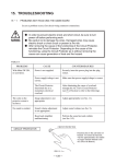
HOUSE OF THE DEAD 4 SUPER DELUXE
OWNERS MANUAL
•
Before using this product, read this MANUAL carefully to understand the contents
stated herein.
•
After reading this MANUAL, be sure to keep it available nearby the product or
somewhere convenient in order to be able to refer to it whenever necessary.
Manufactured in the UK by
MANUFACTURING DIVISION (U.K.)
Contents
1.
Before using this product .......................................................................................................................1
Inspection on immediately transporting the product to location.........................................................2
2.
Introduction to this service manual ........................................................................................................4
3.
Installation and service instructions .......................................................................................................5
3.1. Handling and precautions ..................................................................................................................5
3.1.1. Precautions when moving the machine ......................................................................................6
3.2. Name of general parts........................................................................................................................7
3.3. Installation parts and accessories......................................................................................................8
3.4. Shipping the game board ...................................................................................................................9
3.5. Precautions regarding installation and location ...............................................................................10
3.5.1. Limitations of usage ..................................................................................................................10
3.5.2. Operation area ..........................................................................................................................11
3.6. Assemble the machine.....................................................................................................................11
3.6.1. Connection to the power supply ...............................................................................................19
3.6.2. Connecting the DVD drive (software installation) .....................................................................20
3.6.3. Powering on and software installation. .....................................................................................21
3.7. Precaution regarding product operation...........................................................................................26
3.7.1. Before operation .......................................................................................................................26
3.7.2. During operation (paying attention to customers).....................................................................28
3.8. Assembly check ...............................................................................................................................30
3.9. Fuse locations. .................................................................................................................................34
3.10.
Replacement of fluorescent lamps and other lamps ....................................................................35
3.10.1.
Fluorescent lamp replacement..............................................................................................35
3.10.2.
Standard lamp replacement ..................................................................................................36
3.11.
Troubleshooting............................................................................................................................37
4.
Gameboard ..........................................................................................................................................38
4.1. Removing the game board...............................................................................................................38
4.2. Composition of the game board.......................................................................................................38
4.3. Periodic check and inspection..........................................................................................................39
5.
Game description.................................................................................................................................40
5.1. Game outline ....................................................................................................................................41
5.2. Items.................................................................................................................................................43
5.3. Play hints..........................................................................................................................................44
6.
Maintenance instructions .....................................................................................................................45
6.1. Explanation of test and display test .................................................................................................45
7.
System test mode ................................................................................................................................46
7.1. System test menu ............................................................................................................................46
7.2. System information. .........................................................................................................................47
7.3. Storage information..........................................................................................................................48
7.4. JVS test. ...........................................................................................................................................49
7.4.1. JVS input test............................................................................................................................50
7.5. Monitor test.......................................................................................................................................51
7.6. Speaker test .....................................................................................................................................52
7.7. Coin assignments.............................................................................................................................53
7.7.1. Coin chute type .........................................................................................................................54
7.7.2. Service type ..............................................................................................................................54
7.7.3. Coin chute #1 coin to credit rate. (Coin to credit conversion rate)............................................54
7.7.4. Coin chute #2 coin to credit rate. (Coin to credit conversion rate)............................................54
7.7.5. Detail settings. ..........................................................................................................................55
7.7.6. Game cost setting. ....................................................................................................................56
7.8. Clock setting.....................................................................................................................................57
7.9. Network setting. ...............................................................................................................................58
8.
Game test mode ..................................................................................................................................60
8.1. Input test...........................................................................................................................................61
8.2. Output test........................................................................................................................................62
8.3. Game assignments ..........................................................................................................................63
8.4. Gun calibration settings....................................................................................................................64
8.4.1. Gun mark check........................................................................................................................65
8.4.2. Gun adjustment.........................................................................................................................66
8.4.3. Gun default adjustment.............................................................................................................69
8.5. Gun speed setting ............................................................................................................................70
8.5.1. Gun speed check ......................................................................................................................71
1.1.
ii
8.5.2. Player 1 & Player 2 gun speed adjustment...............................................................................72
8.5.3. Player 1 & Player 2 gun speed default adjustment...................................................................74
8.6. Bookkeeping.....................................................................................................................................75
8.7. Backup data clear ............................................................................................................................77
9.
Gun control unit....................................................................................................................................78
9.1. Replacing the microswitch ...............................................................................................................80
9.2. Replacing the sensor unit.................................................................................................................82
9.3. Replacing the speed sensor unit......................................................................................................83
10.
Projector...............................................................................................................................................84
10.1.
Cleaning the screen......................................................................................................................85
10.2.
Projector adjustment.....................................................................................................................86
10.3.
Colour adjustment ........................................................................................................................88
10.4.
Adjusting contrast .........................................................................................................................89
10.5.
Adjusting brightness .....................................................................................................................90
10.6.
Adjusting cut-off............................................................................................................................91
10.7.
Adjusting drive ..............................................................................................................................92
10.8.
Adjusting screen display position .................................................................................................93
10.9.
Adjusting capture..........................................................................................................................94
10.10. Adjusting the clock........................................................................................................................95
10.11. Adjusting phase ............................................................................................................................96
10.12. White balance switch....................................................................................................................97
10.13. Change input (RGB input / DVI input) ..........................................................................................98
10.14. Display internal test pattern ..........................................................................................................99
10.15. Display internal test pattern ........................................................................................................100
10.16. Special mode: Lamp, timer display and reset ............................................................................101
10.17. Special mode: Force mode.........................................................................................................103
10.18. Special mode: Auto adjust and frame lock setting. ....................................................................104
10.19. Special mode: Re-auto adjust. ...................................................................................................105
10.20. Changing the lamp unit...............................................................................................................106
11.
Coin validator. ....................................................................................................................................109
11.1.1.
VTS P.C board. ...................................................................................................................109
11.1.2.
CREDIT SETTINGS ............................................................................................................110
11.1.3.
VTS credit board option settings .........................................................................................111
11.1.4.
VTS credit board price of play settings (Sterling)................................................................112
11.1.5.
VTS credit board rice of play settings (EURO). ..................................................................113
12.
Periodic inspection.............................................................................................................................114
13.
Troubleshooting. ................................................................................................................................115
13.1.
Problems not involving the Game Board....................................................................................115
13.2.
Replacing the LED board. ..........................................................................................................117
14.
Error codes. .......................................................................................................................................122
15.
Design related parts...........................................................................................................................127
16.
Parts list .............................................................................................................................................128
16.1.
ASSY TOP (HDF-0000UK).........................................................................................................128
16.2.
ASSY DLP (HDF-0500UK) .........................................................................................................129
16.3.
ASSY SUB DLP (HDF-0510UK).................................................................................................130
16.4.
ASSY MASK 52 (HDF-0431UK).................................................................................................131
16.5.
ASSY BILLBOARD DX 62” (HDF-0550UK) ...............................................................................132
16.6.
ASSY SPEAKER L (HDF-0770UK)............................................................................................133
16.7.
ASSY SPEAKER R (HDF-0710UK) ...........................................................................................133
16.8.
ASSY FAN UNIT UK (HOD-1530UK).........................................................................................134
16.9.
ASSY SUB DLP BASE (HDF-0670UK)......................................................................................135
16.10. ASSY 62” GAME BOARD (HDF-4000-01UK) ............................................................................135
16.11. ASSY CABINET DX (HDF-1000UK) ..........................................................................................136
16.12. ASSY SUB CABINET DX (HDF-1100UK)..................................................................................136
16.13. ASSY LIGHT COVER R (HDF-1020UK)....................................................................................137
16.14. ASSY LIGHT COVER L (HDF-1010UK) ....................................................................................137
16.15. ASSY GUN HOLDER L (HDF-1300UK).....................................................................................138
16.16. ASSY GUN HOLDER R (HDF-1350UK) ....................................................................................138
16.17. ASSY CONTROL PANEL (HDF-2000UK) .................................................................................139
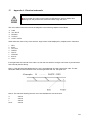
17.
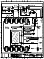
Appendix A - Electrical schematic .....................................................................................................140
17.1.
Electrical schematic....................................................................................................................141
iii
1.
Before using this product
To ensure the safe usage of the product, be sure to read the following before using the product. The following
instructions are intended for the use of QUALIFIED SERVICE PERSONNEL ONLY. After carefully reading and
sufficiently understanding the instructions should any activity be carried out on the product. Only qualified service
personnel should carry out maintenance on the product.
Terms such as WARNING!, CAUTION, and IMPORTANT! Are used where an explanation is given which requires
special attention, depending on the potential risk. SEGA is not responsible for injury or damage caused by use in a
manner contrary to the instructions stated in this document. In order to prevent accidents warning stickers and printed
instructions are applied in the places where a potentially hazardous situation relating to the product could arise. Be sure
to comply with these warnings.
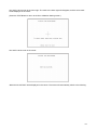
Indicates that mishandling the product by disregarding
this warning will cause a potentially hazardous
situation which can result in death or serious injury.
Indicates that mishandling the product by disregarding this
caution will cause a potentially hazardous situation which
can result in personal injury and or material damage.
This is cautionary information, which should be complied with when handling the product.
Indicates that mishandling the product by disregarding this will cause a potentially hazardous
situation, which may not result in personal injury but could damage the product.
Be sure to turn off the power and disconnect from the mains supply before working on the machine.
Ensure that the correct fuse(s) is fitted to the machine.
Details of the correct fusing of the machine are enclosed in the Service Manual.
Ensure that only qualified Service Engineers perform any maintenance work on the machine.
Specification changes, removal of equipment, conversion and/or addition, not designated by SEGA are not permitted
and will invalidate this product’s CE conformity.
The parts of the product also include any warning labels or safety covers for personal protection etc. A potential
hazard will be created if the machine is operated while any parts have been removed. Should any doors, lids or
protective covers be damaged or lost, do not operate the product. SEGA is not liable in any whatsoever for any injury
and/or damage caused by specification changes not designated by SEGA.
Before installing the product, check for the Electrical Specification Sticker, SEGA products have a sticker on which
the electrical specifications are detailed. Ensure that the product is compatible with the power supply voltage and
frequency requirements of the location in which the machine is to be installed.
When installing this equipment ensure the socket outlet is near the machine and is easily accessible.
Install and operate the machine only in places where appropriate lighting is available, allowing warning stickers to be
clearly read.
To ensure maximum safety for customers and operators, stickers and printed instructions describing potentially
hazardous situations are applied to places where accidents could occur. Ensure that where the product is operated
has sufficient lighting to allow any warnings to be read. If any sticker or printed warning is removed or defaced, do
not operate the machine, until an identical item has replaced it.
When handling the monitor, be very careful. (Applies only to product with monitor)
Some of the monitor (TV) parts are subject to high-tension voltage. Even after turning off the power some
components are still occasionally subject to high-tension voltage. Qualified service engineers should perform monitor
repair and replacement only.
In cases where commercially available monitors and printers are used only the contents relating to this product are
stated in this manual. Some commercially available equipment has functions and reactions not stated in this manual.
Read this manual in conjunction with the specific manual of such equipment.
Descriptions contained herein may be subject to change without prior notification.
The contents described herein are fully prepared with due care. However, should any question arise or errors be
found please contact SEGA.
1
1.1.
Inspection on immediately transporting the product to location
QUALIFIED SERVICE PERSONNEL should only carry out inspection.
Normally, at the time of shipment, SEGA products are in a state to allowing usage immediately after
transporting to the location. Nevertheless, an irregular situation may arise during transportation preventing
this. Before turning on the power, check the following points to ensure that the product has been
transported safely.
Are then any dented parts or defects (cuts, etc.) on the external surfaces of the product.?
Are castors and leg adjusters present and undamaged?
Do the power supply voltage and frequency requirements meet with the local supply?
Are all wiring connectors correctly and securely connected? Unless connected in the correct
direction, connector connections cannot be made successfully. Do not insert connectors
forcibly.
Does the power cord have any cuts or dents?
Do fuses meet the specified rating?
Are such units such as monitors, control equipment, IC BD, etc. firmly secured?
Are all earth wires connected?
Are all accessories available?
Can all doors and lids be opened with the accessory keys and/or tools?
2
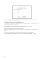
CONCERNING THE STICKER DISPLAY
CONCERNING WARNING STICKERS
SEGA product has stickers describing the product
manufacture number (Serial Number) and
electrical specification. If you require service
assistance you will require the Serial Number.
Identical machines may have different parts fitted
internally. Only by quoting the Serial Number with
the correct parts to be identified.
SEGA product has warning displays on
stickers, labels or printed instructions
adhered/attached to or incorporated in the
places where hazardous situations can arise.
The warning displays are intended for the
accident prevention of customers and service
personnel.
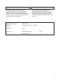
SPECIFICATIONS
Installation Space (cm):
3000 x 2600
Height (cm):
1,503mm × 1,874mm × 2,226mm
Weight (kg):
320kg
Power, Max:
Rated Voltage (V.AC):
230V
Rated Current (A):
3A
Note: Descriptions in this manual are subject to change without prior notice.
3
2.
Introduction to this service manual
SEGA ENTERPRISES LTD., supported by its experience in electronic high technology of VLSI’s,
microprocessors etc. and with a wealth of experience, have for more than 30 years been supplying various
innovative and popular games to the world market. This Service Manual is intended to provide detailed
descriptions together with all the necessary information covering the general operation of electronic
assemblies, electromechanicals, servicing controls, spare parts, etc. as regards HOUSE OF THE DEAD 4
SUPER DELUXE, a new SEGA product. This manual is intended for those who have knowledge of
electricity and technical expertise especially in IC’s, CRT’s, microprocessors etc.. Carefully read this
manual to acquire sufficient knowledge before working on the machine. Should there be any malfunction,
non technical personnel should under no circumstances touch the interior systems. Should such a situation
arise contact the nearest branch listed below or our head office.
SEGA AMUSEMENTS EUROPE LTD.
Suite 3a, Oak House. 12-22 West street, Epsom. Surrey. United Kingdom. KT18 7RG.
Telephone:
+44(0) 1372 731 820
Fax:
+44(0) 1372 731 849
WWW:
http://www.sega-amusements.co.uk
4
3.
Installation and service instructions
QUALIFIED SERVICE PERSONNEL should only carry out installation and
commissioning of this product.
3.1.
Handling and precautions
When installing or inspecting the machine, be very careful of the following points and pay attention to
ensure that the player can enjoy the game safely.
The game must NOT be installed under the following conditions:
• Outside, the game is designed for indoor use only.
• In areas directly exposed to sunlight, high humidity, dust, excessive heat or extreme cold.
• In locations that would present an obstacle in the case of an emergency i.e. near fire equipment or
emergency exits.
• On unstable surfaces or surfaces subject to vibration.
• Where liquids, other than routine cleaning, may come into contact with the game.
Important:
• This machine should only be installed by Qualified Service Personnel.
• Be sure to switch the supply power OFF and remove the mains supply plug from the machine before
any work is carried out on the machine.
• Do not attempt to repair the PCB’s (Printed Circuit Boards) yourself. This will void the warranty. The
PCB’s contain static sensitive devices that could be damaged.
• Always return a faulty part to your distributor with adequate packaging and protection.
• When removing the plug from the mains always grasp the plug not the cable.
• Do not use a fuse that does not meet the specified rating.
• Make sure all connections are secure before applying power.
Ensure that the mains lead is not damaged. If the mains lead is damaged in any
way there could be a danger of electric shock or a fire hazard.
Ensure that the power supply is fitted with circuit protection. Using the power
supply without circuit protection is a fire hazard.
5
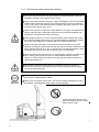
3.1.1. Precautions when moving the machine
When moving the machine, be sure to pull out the plug from the power supply.
Moving the machine with the plug still inserted can cause the power cord to be
damaged, resulting in a fire and/or electric shock.
When moving the machine on the floor, retract the adjusters, and ensure that the
casters make contact with the floor. Pay careful attention so that the casters do
not run over power cords and earth wires. Damaging the power cords can cause
an electric shock and/or short circuit.
When moving across an area with a sharp difference in height, first separate the
cabinet and ASSY DIP. Tilting them whilst the two are still joined together may
damage the connectors and could cause injury.
When lifting the cabinet, be sure to hold the handles and the bottom part. Lifting
the cabinet by holding other portions may damage parts and installation portions
due to the empty weight of the cabinet, and may cause personal injury.
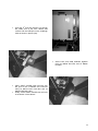
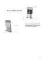
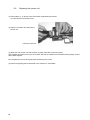
When moving the ASSY DLP, do not push it from the rear side. Push it from
sideways. Pushing the ASSY DLP from the rear side can have the ASSY DLP fall
down, causing personal injury, etc. In case the floor has slanted surfaces or steplike differences, be sure to move the machine by 2 or more persons.
When the cabinet and ASSY DIP are not connected the cabinet is unstable on its
own. Pushing it may cause it to fall over. When detached always keep the
cabinet on a level surface and make sure it does not start to lean to the left or
right whilst working on it.
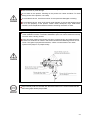
Do not hold or press the plastic parts as indicated by the Figure. Failure to
observe this instruction may break the parts, and eventually the broken pieces
may cause a personal injury.
When moving the cabinet do not hold or push the gun holders. This could deform
their shape or cause damage to them.
Never push on the projector's screen. The screen is easily damaged but cannot
be repaired. If damaged the entire screen must be replaced.
Pushing the ASSY DLP from the
back may make it fall over. Always
push it from the side.
6
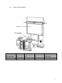
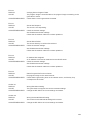
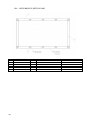
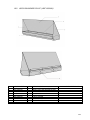
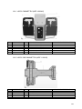
3.2.
Name of general parts
Width (cm)
Length (cm)
Height (cm)
Weight (kg)
ASSY DLP
212
68
228
200kg approx
ASSY GUN CABI
121
135
97
150kg approx
When Assembled
212
192
228
350kg approx
7
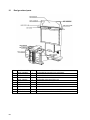
3.3.
Installation parts and accessories
The machine is supplied with an installation kit. Please ensure the following parts are supplied:
SEQ
**1
**2
**3
**4
**5
**6
**7
**8
**9
**301
**302
**401
**402
**403
**404
**405
**406
**407
**408
**409
***2
***3
***4
***5
***8
***9
***202
PT NUMBER
440-CS0186UK
SAECE-135
HDF-2003UK
540-0043-91
540-0006-01
540-0007-01
HDF-0405UK
HDF-0406UK
610-0727-003
LM1246
LM1227
OS1019
420-6908-01UK
XXX-XXXX-LG
350-5801
509-5080
514-5078-2000
514-5079-10000
514-5078-10000
514-5090-3000
HDF-0452UK
HDF -0453UK
HDF-0454UK
HDF-0455UK
HDF-0454BUK
HDF-0455BUK
030-000620-SB
DESCRIPTION
STICKER C EPILEPSY MULTI
DECLARATION OF CONFORMITY
DECAL INST PLATE HDF SDX MULTI
L-WRENCH FOR HEX SOC 3MM
WRENCH M4 TMP PRF
WRENCH M5 TMP PRF
ASSY BANNER R
ASSY BANNER L
DVD SOFT KIT HDF
EUROLEAD 10A EUROPEAN SOCKET
UK MAINS LEAD 10A WITH PLUG
SELF SEAL BAG 9X12.3/4
SERVICE MANUAL HDF SDX 52
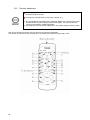
LG DISPLAY MANUAL + REMOTE CONTR
MOTOR DC5V TG-01H
SW MICRO TYPE (SS-5GL2)
FUSE 2A CER 20MM RS419-779
FUSE 10A T CER 32MM RS414-061
FUSE 5X20 CERAMIC SB 10000MA
3A FUSE 6.3MMX25MM CERAMIC T
BRKT LIGHT BILLBOARD PLATE
BILLBOARD PLATE (fixed to ITEM 2)
SUPPORT LEFT
SUPPORT RIGHT
ARTWORK SIDE L (fixed to ITEM 4)
ARTWORK SIDE R (fixed to ITEM 5)
M6X20 BLT W/S BLK
Item 5 AND 6 - Tamper-proof TORX wrenches
8
QTY
1
1
1
1
1
1
1
1
1
1
1
2
1
1
2
2
3
1
1
1
1
1
1
1
1
1
12
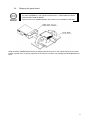
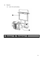
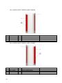
3.4.
Shipping the game board
• When returning the GAME BOARD for repair or replacement, be sure to package
the entire ASSEMBLY in the original card transit box - THERE ARE NO USERSERVICEABLE PARTS INSIDE.
• Failure to return the GAME BOARD in this manner may invalidate the warranty.
Wrap the ASSY GAME BOARD with the packaging material and put it in the original transit box as shown.
Putting it upside down or packing otherwise in the manner not shown can damage the GAME BOARD and
parts.
9
3.5.
Precautions regarding installation and location
Perform the assembly by following the procedure herein stated. Failure to comply with
the instructions, for example, inserting the plug into an outlet at a stage not mentioned in
this manual can cause an electric shock
Assembling should be performed as per this manual. Since this is a complex machine,
erroneous assembling can cause damage to the machine, or malfunction to occur.
Do not attempt to complete this work alone, a minimum of 2 people are required.
QUALIFIED SERVICE PERSONNEL should only carry out assembly work.
This product is an indoor game machine. Do not install it outside. Even indoors, avoid
installing in places mentioned below so as not to cause a fire, electric shock, injury and/or
malfunction.
Places subject to rain or water leakage, or places subject to high humidity in the
proximity of an indoor swimming pool and or shower, etc.
Places subject to direct sunlight, or places subject to high temperatures in the proximity
of heating units, etc.
Places filled with inflammable gas or vicinity of highly inflammable/volatile chemicals or
hazardous matter.
Dusty places.
Sloped surfaces.
Places subject to any type of violent impact.
Vicinity of anti-disaster facilities such as fire exits and fire extinguishers.
The operating (ambient) temperature range is from 5℃ to 30℃.
3.5.1. Limitations of usage
Be sure to check the Electrical Specifications. Ensure that this product is compatible with
the location's power supply, voltage and frequency requirements. A plate describing
Electrical Specifications is attached to the product. Non-compliance with the Electrical
Specifications can cause a fire and electric shock.
This product requires a breaker and earth mechanism as part of the location facilities.
Using the product without these can cause a fire and electric shock.
Ensure that the indoor wiring for the power supply is rated at 15A or higher (AC single
phase 100Ṽ 120V area), and 7A or higher (AC 220V~ 240V area). Non-compliance
with the Electrical Specifications can cause a fire and electric shock.
Be sure to use an independent power supply equipped with a surgesuppressor.
Using a power supply without a surge-suppressor can cause an outbreak of fire if a power
surge occurs.
Putting many loads on one electrical outlet can cause generation of heat and a fire
resulting from overload.
When using an extension cord, ensure that the cord is rated at 15A or higher (AC
100Ṽ 120V area) and 7A or higher (AC 220V ~ 240V area)
Using a cord rated lower than the specified rating can cause a fire and electric shock
10
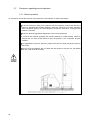
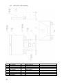
3.5.2. Operation area
For the operation of this machine, secure a minimum area of 2.6m (8.5ft) (W) x 3.0m
(9.8ft) (D). In order to prevent injury resulting from falls/accidents during game play, be
sure to secure the minimum area for operation.
Be sure to provide sufficient space (20cm minimum) so as to allow this product's
ventilation fan to function efficiently. To avoid machine malfunctions or fires, do not place
any obstacles near the ventilation opening.
Do not allow objects to block the ventilation ports. It can cause generation of heat and a
fire.
SEGA shall not be held responsible for damage or compensation for damage to a third
party, resulting from the failure to observe this instruction.
3.6.
Assemble the machine
When carrying out the assembly work, follow the procedure in the following sequence.
STEP 1
STEP 2
STEP 3
STEP 4
Assemble the machine.
Leg levelling procedure.
Billboard installation procedures.
AC wiring and connection procedure.
Note that the parts contained within the installation kit are required for the assembly work.
Fit all fixings loosely first as detailed in step 1, then position all components before
finally tightening fixings at step 4.
QUALIFIED SERVICE PERSONNEL should only carry out this operation.
11
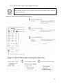
Step 1 (Assemble the machine)
• This operation should only be carried out by QUALIFIED SERVICE
PERSONNEL.
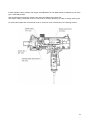
Step 1
•
Remove the JOINT COVER (HDF1031UK) from over the joint of the 2
cabinets (2x M5x16 PAN PAS BLK and
2x M6x50 HEX BOLT BLK.)
Gun Cabinet
•
Join both DLP and GUN cabinets as pictured
(left).
DLP Cabinet
12
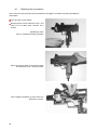
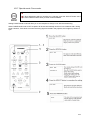
•
Feed the harnesses from the Gun cabinet
up through the access hole in the DLP
cabinet.
•
Make all 5 harnesses connection good.
•
Feed the 6th and final harness up through
the inside rear of the DLP cabinet and
connect into the USB port on the Lindbergh
CPU as shown in picture (left).
•
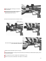
•
•
Secure DLP and GUN Cabinets together
using 2x M8x30 Hex Bolt and 2x M8x65
Hex Bolt
Place JOINT COVER (HDF-1031UK) over
the joint of the 2 cabinets and re-secure
using 2x M5x16 PAN PAS BLK and 2x
M6x50 HEX BOLT BLK.
Finally, fit the CABLE COVER over the hole
in the bottom of the cabinet.
13
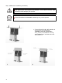
Step 2 (Leg levelling procedure)
Make sure all of the leg adjusters are in contact with the floor. If they are not the
machine may move and cause injury. This operation requires 2 people.
QUALIFIED SERVICE PERSONNEL should only carry out this operation.
The cabinet is equipped with 8 casters (4 for DLP Base and 4 for Cabinet) and 6 adjusters (4 for DLP Base
and 2 for Cabinet). After deciding on a location, bring the adjusters into direct contact with the ground and
adjust the cabinet so that it is completely level. If the floor is level, the machine should be level with the
casters about 5 millimeters from the floor.
Move the cabinet to the desired location. Make sure there is space in the back for air to flow.
Bring the adjusters into direct contact with the floor. Use a wrench to align the height of the
adjusters until the cabinet is perfectly level.
After making the final adjustments, fix the adjuster height by tightening up the adjuster nuts.
Underside view
After securing the leg adjuster bolts, fully tighten all bolts temporarily attached in step 1 above.
14
Ensure adequate ventilation is maintained as detailed below.
15
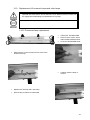
Step 3 (Billboard installation procedure)
One person alone cannot perform the installation of the billboard assembly. Seek
assistance before attempting this operation.
QUALIFIED SERVICE PERSONNEL should only carry out this operation.
•
16
Fit the SUPPORTS L&R (HDF-0454UK and
HDF-0455UK) and the BANNER
ASSEMBLY L&R (HDF_0405UK and
HDF_0406UK) to the Billboard Assembly
using 8x M6x20 BLT W/S BLK and 8x M6
WASHERS BLK.
•
Place the BILLBOARD PLATE (HDF0453UK) on the back of the SUPPORTS
L&R and secure along the bottom edge
using 4x M6x12 MCSR PAN W/FS PAS.
•
•
Remove the END CAPS BANNER (HDF0406UK) from both BANNER SUPPORTS.
Slide both BANNERS L&R (HDF-0403UK &
HDF-0404UK) onto the supports and resecure the END CAPS BANNER.
17
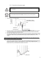
Step 4 (AC wiring and connection procedure)
• Be sure that the machine is not connected to the mains supply before attempting this
operation
• QUALIFIED SERVICE PERSONNEL should only carry out this operation.
Be sure to independently use the power supply socket outlet equipped with an Surge
Suppressor. Using a power supply without a Surge Suppressor can cause a fire when
electric leakage occurs.
Ensure that the "accurately grounded indoor earth terminal" and the earth wire cable
are available (except in the case where a power cord plug with earth is used). If the
grounding work is not performed appropriately, customers can be subjected to an
electric shock, and the product may not function properly.
Ensure that the power cord and earth wire are not exposed on the surface (passage,
etc.). If exposed, they can be caught and are susceptible to damage. If damaged, the
cord and wire can cause electric shock and short circuit accidents. Ensure that the wire
is not in the customer's way and that the wiring has protective insulation.
After wiring the power cord on the floor, be sure to protect the power cord. An exposed
power cord is susceptible to damage and may cause an electric shock.
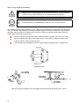
When using the earth terminal from Terminal width:12mm the AC unit for the product,
always use an earth wire with a round earth terminal as shown in the diagram and be
sure to connect it correctly. Never use simply stripped wires or any other form of
inappropriate connection method.
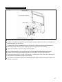
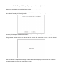
The AC unit is located at the base of the back of the DLP. The AC unit has the following
switches/connectors.
The main switch
An inlet for the power cable.
The power cable included with the product has an earth wire inside.
Connect the AC unit to the power cable and then plug it into a socket that has an earth terminal. If you do
not have access to a socket with an earth terminal you must earth the product in another way, e.g. by
connecting the AC unit's earth terminal and an earth device via a separate earth cable. If you are using a
commercial conversion adaptor to provide the power you must connect the adaptor's earth terminal to an
earth terminal that is definitely earthed.
18
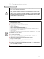
3.6.1. Connection to the power supply
• Be sure that the machine is not connected to the mains supply before attempting
this operation
• QUALIFIED SERVICE PERSONNEL should only carry out this operation.
1. Ensure that the main switch is OFF.
2. Insert the connector on the non-power plug end of the power cord into the AC unit's inlet. Pass the
connector through the hole in the base of the satellite and insert it firmly into the AC unit's inlet.
3. Insert the power plug firmly into a power socket.
4. If you are using a separate earth cable connect one end of the earth to the earth terminal on the AC
unit and the other end to your in-store earth terminal. The AC Unit earth terminal has a Bolt and Nut
combination. Take off the Nut, pass the earth wire through the Bolt, and fasten the nut. <For
Taiwan>
*Note that the earth wire is incorporated in the power cord for the Areas of AC 120V (USA) and AC 220 ~
240V, and therefore, this procedure is not necessary.
5. Firmly insert the power plug into the socket outlet. Insert the opposite side of the power cord plug to
the AC Unit's connector ("INLET"). Perform wiring for the power cord and earth wire. Install
protective insulation for the power cord and earth wire. If you are using a separate earth to earth the
product make sure you install protective insulation for this also.
19
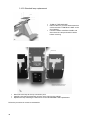
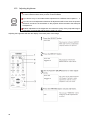
3.6.2. Connecting the DVD drive (software installation)
The software for this product is pre-loaded from the factory. The information and guide lines within this
chapter are for reference purposes only.
These procedures will only be implemented if the LINDBERGH is replaced or the SOFTWARE is updated.
For safety's sake, prepare to perform the software install prior to turning on the power. You will need the
included DVD Drive, DVD wire and DVF software kit.
Connect the end of the DVD wire with the
"DVD" tag on it to the two connectors
on the DVD DRIVE.
Connect the end of the DVD wire with the
"LINDBERGH" tag on it to the two
connectors on the LINDBERGH board.
There are 4 USB connectors on the
LINDBERGH board, any of which may be
used.
20
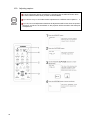
3.6.3. Powering on and software installation.
Caution when using the DVD Drive
Looking directly into the internal laser in the DVD drive may damage your vision.
Never look into the interior of the DVD drive.
When connecting the DVD wire connectors be sure to insert them in the correct direction
and angle.
There is only one correct way to connect them. Attempting to force the connectors together
incorrectly or connecting them at the incorrect angle may damage the connectors or their
pins and create a fire risk or a short circuit.
Be very careful not to trap or damage the DVD wire. This could cause a short circuit or a
fire risk.
Do not use or store the DVD drive or DVD wire in any of the following locations, as this may
lead result in serious damage.
Do not use or store in these locations
Anywhere which may vibrate or shock the equipment
In direct sunlight
In damp or dusty placed
In places with a sharp change in temperature
Close to anything that gives off heat (a heater, etc.)
Close to anything with a strong magnetic field (magnets, monitor, speakers, radio, etc.)
Anyway that is likely to get wet (kitchen, etc.)
Anywhere sloping
Anywhere with corrosive gas in the air (chlorine, hydrogen sulfide, ammonia, sulfur dioxide,
etc.)
Anywhere with strong static electricity
Do not use in these locations
Close to anything that is highly retentive of heat (carpet, sponge, cardboard, etc.)
Anywhere that blocks the DVD drive air vent.
The DVD drive is a delicate piece of equipment. Avoid the following.
Dropping or shaking it violently.
Getting water or other liquids on it, or placing small items on top of it.
Placing large or heavy items on top of it.
Drinking or smoking close to the DVD drive.
Do not turn off the power to the DVD drive when its access lamp is on or flashing, as this
could cause damage to the device.
Do not allow any foreign materials, such as liquids, metals or smoke inside the DVD drive.
21
Use a soft, dry cloth to wipe off any dirt or marks on the DVD drive.
If you need to use a cleaning agent, always use a "neutral" agent diluted in water.
Never use products or cleaning agents containing benzene, alcohol, thinners, etc.
Do not touch the lens inside the DVD drive. Doing so may prevent it from reading
accurately.
The chip components on IC boards can be damaged by electrostatic discharge from the
human body. Before handling an IC board, always neutralize any static charge in the
body by touching a grounded metal surface.
Handling the DVD-ROM Disc
Do not use a DVD-ROM with a damaged front. This may cause a malfunction.
Insert the DVD-ROM into the DVD drive with the label facing upwards.
Do not get fingerprints or dust particles on the disc. Contaminated discs may lower
audio and video quality, and may result in read malfunctions.
When cleaning the disc, do not use volatile chemicals (benzene, thinner, etc.), cleaning
sprays, or antistatic agents.
Do not use a cracked, warped, or damaged disc. Do not attach papers or seals onto the
disc to avoid scratching it. Do not use a disc with signs of peeled seals, tape, etc. If
such a disc is placed in the DVDROM drive, malfunctions, such as the inability to
remove the disc from the drive, may result.
When cleaning a heavily contaminated disc, use a clean cloth that has been soaked in
water and squeezed. After wiping, remove any remaining moisture with a clean, dry
cloth.
How to Hold a Disc
When handling a disc, be careful not to contaminate it
with your fingerprints.
With both hands:
Put your thumbs and forefingers on 4 opposite sides
of the disc.
With one hand:
Insert your forefinger into the center hole, while
placing your thumb and middle finger on opposite
sides of the disc.
22
Caution Software Installation
The product does not come with software installed, so simply turning on the power and
leaving the cabinet alone will cause an error. If such an error occurs set the DVD disc
into the DVD drive and restart the machine. Installation will take place.
Due to initialization of the DVD drive, the tray will not come out even if the button is
pressed for about 30 seconds after turning on the power.
Always open the DVD drive's tray and insert/remove DVDs with the power switched on.
The tray will not open with the power off.
Keep the DVD software kit, DVD drive and DVD wire safe even after the software
installation is complete.
If for any reason the installation is not possible, an error will be displayed.
Prepared the attached DVD software kit and sticker "844-0002D-02."
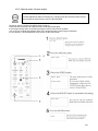
The process as described below features numerous time-consuming steps, such as restarting the power
and taking side door L on and off. Each of these steps is required to avoid electric shocks and the operation
should be performed exactly as detailed below.
Turn the AC unit's main switch ON to supply power. The florescent lights in the billboard and the
cold-cathode tube inside the lighting should come on.
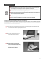
Remove the 1 plastic-head screw and
remove the DVD drive case lid.
Wait approximately 30 seconds after
turning on the power and then press
the switch on the DVD drive. The tray
will come out. Insert the DVD from the
DVD software kit. Make sure that the
label side is facing upwards.
23
The software will install automatically from the DVD. The message "Check Release Image ・・・
XX.XX%" will be displayed on the screen.
Once the install finishes, the game screen will be displayed. The install takes about five minutes. Once it
is finished remove the DVD. Press the switch on the DVD drive and the tray will open. Take the DVD
out.
Press the switch on the DVD drive and close the tray again. The tray will not move once the power is off
so be sure to do this before turning off the power.
Turn the main switch on the AC unit OFF.
Remove side door L.
Undo the two cord clamps holding the DVD wire in place and disconnect the DVD wire connectors
attached to the LINDBERGH board. Leave the keychip inserted.
Stick the sticker "844-0002D-02" onto the LINDBERGH board. The LINDBERGH board initially has a
sticker "844-0001D-02" on it. Place the new sticker over this old one.
Place the plate DVD back into side door L and fix it in place with the two truss screws.
Replace side door L on the cabinet and lock it.
Fix side door L in place with the three truss screws.
Replace the DVD drive's case lid and fix it in place with the plastic-head screw.
Store the DVD drive, DVD wire and DVD software kit in a place free from dust and cigarette smoke.
24
Turning on Power after Software Install
Turn the main switch on the AC unit ON to supply power.
As soon as the power is supplied the fluorescent lamps inside the billboard and the cold-cathode tubes
inside the lighting unit will come on.
A few seconds later the LINDBERGH start-up screen will be displayed and then the Advertisement
Mode (Attract Mode) will start, which displays a demo of the game and score rankings.
It takes approximately 3 minutes to reach the Attract Mode.
During Attract Mode sound will be emitted from the left and right speakers beneath the projector.
However if sound during Attract Mode is turned off in TEST Mode, no sound will be emitted.
Even if the product's power is turned off the number of credits played, ranking data, game difficulty and
other settings and bookkeeping data will all be saved.
The number of incomplete credits (coins inserted that did not equal a credit) and the bonus adder count
data will not be saved.
25
3.7.
Precaution regarding product operation
3.7.1. Before operation
To avoid injury and trouble, be sure to pay attention to the behavior of visitors and players.
In order to avoid accidents, check the following before starting the operation:
To ensure maximum safety for the players and the customers, ensure that where the
product is operated has sufficient lighting to allow any warnings to be read. Operation
under insufficient lighting can cause players to bump into each other, causing trouble
between customers.
Be sure to perform appropriate adjustment of the monitor (projector).
Do not leave the machine operating with monitor flickering or malfunctioning. Failure to
observe this can have a bad influence upon the players' or the customers' physical
condition.
It is suggested to ensure a space for players who feel sick while playing the game to
take a rest.
Check if all of the adjusters are in contact with the surface. If they are not, the cabinet
can move and cause an accident.
26
Do not put any heavy items on this product. Placing heavy items on the product can
cause accidents or parts damage.
Do not climb on the product. Climbing on the product can cause accidents. To check
the top portion of the product, use a step.
To avoid electric shock, check that no door & cover parts are damaged or missing.
To avoid electric shock, short circuit and or parts damage, do not put the following items
on or in the periphery of the product. Flower vases, flowerpots, cups, water tanks,
cosmetics, and receptacles/containers/vessels containing chemicals or water.
To avoid injury, be sure to provide sufficient space by considering the crowd situation
at the installation location. Insufficient installation space can cause customers to bump
into each other, causing trouble.
Every day when cleaning the Control Unit (Gun), inspect the gun and make sure that
there are no scratches or cracks in the surface, and that the fastening screws are not
loose. If the game is played with scratches, cracks or loose screws it can cause
injuries to the player or to people nearby.
Players directly hold the controller with their bare hands so it is recommended that the
wet towels (paper towels) be provided.
27
3.7.2. During operation (paying attention to customers)
To avoid injury and trouble, be sure to pay attention to the behavior of visitors and players.
To avoid injury and accidents, those who fall under the following categories should
refrain from playing the game.
- Those who need assistance such as the use of an apparatus when walking.
- Those who have high blood pressure or a heart problem.
- Those who have experienced muscle convulsion or loss of consciousness when playing
video games, etc.
- Those who have neck or spinal cord problems.
* Intoxicated persons.
* Pregnant women or those who could be pregnant.
* Persons susceptible to motion sickness.
* Persons who disregard the product's warning displays.
Even players who have never been adversely affected by light stimulus might
experience dizziness or headache depending on their physical condition when playing
the game. Small children are especially likely to experience these symptoms. Caution
guardians of small children to keep watch on their children during play.
It is suggested to provide a space for players who feel sick while playing the game to
take a rest.
Instruct those who feel sick during play to have a medical examination.
To avoid injury from falls and electric shocks due to spilled drinks, instruct the player not
to place heavy items or drinks on the product.
To avoid electric shocks and short circuits, do not allow customers to put hands and
fingers or extraneous matter in the openings of the product or small openings in or
around the doors.
To avoid falls and resulting injury, immediately stop the customer from leaning against
or climbing on the product, etc.
To avoid electric shocks and short circuits, do not allow customers to unplug the power
plug.
Be sure to instruct the adult responsible for their children to watch them. Children
cannot sense danger. Approaching the player during play may result in accidental
contact, collisions or falls. If the gun is pulled from the gun holder and dropped on the
head, it may cause injury.
Caution the player not to wrap the gun cord around his/her wrist or neck, as this can
lead to serious injury.
28
Immediately stop such violent acts as hitting and kicking the product. Such violent acts
can cause parts damage or cause the cabinet to fall over, resulting in injury.
Immediately stop users from leaning or sitting on the gun holder. Such acts can lead to
injury or damage to parts or the shape of the cabinet.
Immediately stop users from swinging or reloading the Control Unit (Gun) in a violent
manner. Such acts may hurt the user or other people around them.
Playing too close to the cabinet may cause the Control Unit (Gun) to hit the cabinet and
cause damage. Make sure that players understand to play at a safe distance from the
cabinet.
Make sure that players understand not to stand too close together when playing a twoplayer game. Swinging the Control Unit (Gun) could lead to a player getting hit and may
cause injury.
Make sure that players understand to hold the Control Unit (Gun) firmly during play.
Dropping the Control Unit (Gun) could cause damage to it or injure the player.
Larger rings and other such accessories may lead to injury to fingers during play. Make
sure that players understand to remove any accessories prior to playing the game that
may cause such accidents.
Make sure that players understand that more than one person is not allowed to play
with a single Control Unit (Gun). Such play could lead to various injuries.
Make sure to avoid disturbing customers when moving/removing the machine from its
current location.
The Control Units (Guns) for use on 1P side (left side) and 2P side (right side) are
different. Ensure that players do not confuse the right and left side guns when starting
play.
29
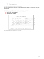
3.8.
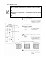
Assembly check
QUALIFIED SERVICE PERSONNEL should only carry out this operation.
Use Test Mode to check that the product has been assembled correctly and that the game board, other
connected boards and all output devices are working correctly.
Perform this test in Test Mode as follows.
See "9-2 System Test Mode" for tests (1) to (4) below and "9-3 Game Test Mode" for test (5) to (7).
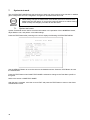
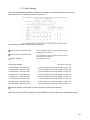
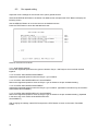
(1) Information Display Screen
Selecting SYSTEM INFORMATION, STORAGE INFORMATION or JVS TEST from the SYSTEM TEST
Mode menu screen will displayed system information, game information and information concerning the
JVS I/O board attached to the LINDBERGH board.
If all information is displayed correctly then the LINDBERGH board is running smoothly.
(2) JVS Input Test Screen
Selecting INPUT TEST on the JVS TEST Screen will display input data for the JVS I/O board.
For this product this is the screen to test the coin switches. Insert a coin to perform a test.
If the display nest to the switch changes the switch and connections are working correctly.
(3) Monitor Test Screen
Selecting MONITOR TEST on the SYSTEM TEST Mode menu screen will display a screen that allows the
monitor output to be tested.
The projector comes adjusted from the factory but still use this TEST Screen to make sure that further
adjustment is not required. If required, see chapter 11 for information on adjusting the projector.
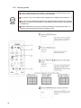
(4) Speaker Test Screen
Selecting SPEAKER TEST from the SYSTEM TEST Mode menu screen will display a screen that allows
the speaker output to be tested.
The speakers attached to the machine will output a test sound. Use this to check that all speakers are
outputting correctly.
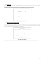
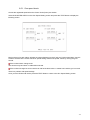
(5) Input Test
Selecting INPUT TEST from the GAME TEST Mode menu screen will display a screen that allows input
devices to be tested.
Press each switch to check that each is working. If the display next to the input device changes to on "ON"
or the values displayed change smoothly then that input device and all connections with it are working
correctly.
Input Test Screen
30
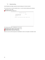
(6) Output Test
Selecting OUTPUT TEST from the GAME TEST Mode menu screen will display a screen that allows output
devices to be tested.
Operate the lamps and other output devices and check that they are all working correctly.
Output Test Screen
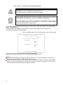
(7) Calibration Check and Speed Check
Prior to letting customers use the game you must play a game and make sure that everything is operating
correctly. Although adjusted prior to leaving the factory incidents in transit may have affected these settings
and so check to make sure that adjustment is not required.
Gun Mark Check Screen
You should perform the above checks once a month. However (7) should be performed at least once a
week.
31
Interference Prevention Wiring
In order to prevent electric shock and short circuit hazards, be sure to turn power off
before performing work.
Be careful not to damage the wires. Damaged wires may cause electric shock or short
circuit or present a fire risk.
Do not expose the IC board, etc. unless absolutely necessary. Failure to observe this
can cause electric shock hazard or malfunctioning.
This work should be performed by the site maintenance personnel or other qualified
professionals. Performing work by non-technical personnel can cause a severe accident
such as electric shock.
When the game machines of a same or similar type are installed side by side, their sensors may interfere
with each other. To reject the interference, follow the procedure below.
The following game machines employ a same or similar type of sensor. If interference happens to the
sensors, operation of the games may be mutually disturbed.
THE HOUSE OF THE DEAD 2, U/R type, DX type and Super DX type
DEATH CRIMSON, U/R type and DX type
THE LOST WORLD, U/R type, DX type and Super DX type
BRAVE FIRE FIGHTERS
SAMBA DE AMIGO
CONFIDENTIAL MISSION, U/R type and DX type
SHAKATTO TAMBOURINE
LUPIN THE 3RD THE SHOOTING, U/R type and DX type
THE MAZE OF THE KINGS, U/R type and DX type
THE HOUSE OF THE DEAD 3, U/R type and DX type
VIRTUA COP 3, U/R type and DX type
GHOST SQUAD, U/R type and DX type
THE HOUSE OF THE DEAD 4
32
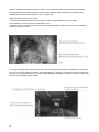
a. Turn the power off.
b. Undo the 2 truss screws and remove
side door from the cabinet.
c. The interference prevention wire
connected to the IC board inside
cabinet.
d. If multiple units of the same game
installed side by side, make sure that
game units that are connected to
interference
prevention
wires
arranged so that they alternate with
units that are not connected.
the
is
the
are
the
the
are
the
INTERFERENCE PREVENTION WIRING
HDF-60032
33
3.9.
Fuse locations.
In order to prevent electric shock and short circuit hazards, be sure to turn power off
before performing work.
Be careful not to damage the wires. Damaged wires may cause electric shock or
short circuit or present a fire risk.
Do not expose the Game BD, etc. without a good reason. Failure to observe this can
cause electric shock hazard or malfunctioning.
Do not use this product with connectors other than those that were connected and
used with the Game Board at the time of shipping. Do not carelessly connect wires to
connectors that were not used at the time of shipping, as this may cause
overheating, smoke or fire damage.
When replacing or repairing the game board and then returning it to the cabinet, be
sure to reconnect all the connectors correctly. Improper connection may cause
electric shock, short circuit or fire.
When connecting the connectors, be sure to attach them correctly.
There is only one correct way in which they must be connected.
Attempting to connect them incorrectly may cause damage to the pins on the
connectors, and cause electric shock, short circuit or fire.
In this product, setting changes are made during the Test Mode. The Game BD need
not be operated. Use the Game BD, etc. as is with the same setting made at the time
of shipment so as not to cause electric shock and malfunctioning.
Static electricity from your body may damage some electronics devices on the IC
board. Before handling the IC board, touch a grounded metallic surface so that the
static electricity can be discharged.
When exchanging the game board place and post off the damaged board in the new
board's special packaging. If you do not have the packaging or it is damaged order
one using the following product number/name <601-11691: CARTON BOX LBG>.
When sending a board for repairs or do not dismantle the board in any way prior to
sending it away. It may not be possible to meet your request if any parts are missing.
Send a game board in for repair with the key chip still inserted.
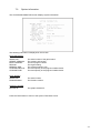
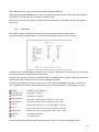
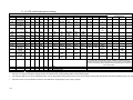
There are a number of fuses used on this machine to protect the user and the machine from damage. Only
replace the fuse once you have remove the cause of its failure. Detailed below is a list of the fuses used,
their location and if relevant P.C.B. reference:
PART NUMBER
514-5078-2000
514-5078-2000
514-5079-10000
514-5090-3000
514-5078-10000
34
LOCATION
WH HDF (60033UK)
WH HDF 60029-02UK)
XFMR (560-LGBH-UK)
FL UNIT (390-7001-30UK)
IEC INLET (EP1387)
TYPE & DETAILS
2A T CERAMIC 20X5MM
2A T CERAMIC 20X5MM
10A T CERAMIC 32X6.3MM
3A T CERAMIC 25X6.3MM
10A T CERAMIC 20X5MM
QTY
2
4
1
1
1
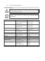
3.10. Replacement of fluorescent lamps and other lamps
• Never touch places other than those specified. Touching places other than those
specified can cause electric shock and short circuit. Disconnect the machine from
the supply before attempting the replacement of any lamp.
• Lamps should only be replaced by QUALIFIED SERVICE PERSONNEL.
3.10.1.Fluorescent lamp replacement
•
•
TURN OFF THE MACHINE.
•
Remove the 4 screws, which
retain the BILLBOARD sheet.
•
Lift off the BILLBOARD sheet.
•
Carefully twist the lamp to
remove.
Slide back the covers located over the ends of the
Fluorescent lamp.
•
Replace the old lamp with a new lamp.
•
Reverse the procedure to reassemble.
35
3.10.2.Standard lamp replacement
•
•
•
•
•
•
Disconnect the lamp at the top connection point.
Carefully raise the lamp assembly unit the unit is free from the cabinet.
Replace the lamp following the instructions for the BILLBOARD LAMP replacement.
Follow the procedure in reverse to reassemble.
36
TURN OF THE MACHINE.
Remove the four (4) truss head screws that
secure the ASSY CONTROL PANEL to the
Gun Cabinet.
Lift off the ASSY CONTROL PANEL and
disconnect the Lamp and switch holders
before removing.
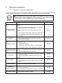
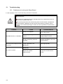
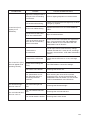
3.11. Troubleshooting
• These procedures should only be carried out by QUALIFIED SERVICE
PERSONNEL.
If a problem occurs, first check the wiring connections.
PROBLEMS
When the main
switch is turned ON,
the machine is not
activated.
CAUSE
COUNTERMEASURES
The power is not ON.
Firmly insert the plug into the outlet.
Incorrect power source/voltage.
Make sure that the power supply/voltage
are correct.
AC Unit CIRCUIT PROTECTION
DEVICE (i.e.; fuse) was activated due
to an instantaneous over current.
First, remove the cause of over current
and reinstate the circuit protection device
to its original status.
Then identify the cause of the fault on the
item, which caused the over current, & fix.
The colour image on
the screen is
incorrect.
Incorrect monitor adjustment.
Make appropriate adjustments.
The on-screen image
of the monitor sways
and/or shrinks.
The power source and voltage are not
correct.
Make sure that the power supply and
voltage are correct.
Sound volume adjustment is not
correct.
Adjust the volume setting on the VTS
bracket.
Malfunctioning BD and Amp.
Perform Sound Test to check it.
Connector connection is incorrect.
Check connector connection from Base to
Speaker.
VR malfunctioning.
Replace the V.R.
Sighting is inaccurate due to
environmental conditions, etc.
Adjust the gun sighting alignment.
Micro switch malfunctioning.
Replace the micro switch.
Sensor BD is malfunctioning.
Replace the Sensor BD.
Fluorescent lamp needs replacement.
Replace the fluorescent lamp.
The connector is disconnected.
Check connector connections in the
billboard case.
Sound is not emitted.
Controller operation
is not satisfactory.
The fluorescent lamp
does not light up.
The lamp needs replacement.
The LEADER lamp
does not light up.
Interactive play is not
possible.
Replace the lamp.
The connector is disconnected.
Check connector connections in the
billboard case.
Communication cable is disconnected.
Connect the cable.
Cable connections are not correct.
Settings for communication play are not
correct.
Connect the cable correctly.
Ensure that GAME ASSIGNMENTS
settings are correct.
37
4.
Gameboard
Turn off the mains power and remove the power cord before opening the machine.
The GAME BOARD should not require any work to be carried out upon it. All
settings and tests can be achieved without access to the GAME BOARD.
All work to be carried out by QUALIFIED SERVICE PERSONNEL
4.1.
Removing the game board
The LINDBERGH game board can be found in the base of the display cabinet.
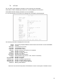
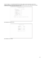
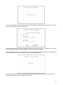
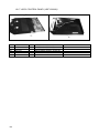
4.2.
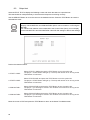
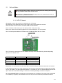
Composition of the game board.
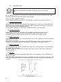
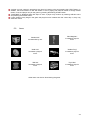
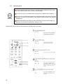
The game board becomes the game board for this product once the key chip is
inserted.
The DIP SW (dip switches) on the board must be set as specified below. If set
incorrectly for this product, an error will be displayed and the game will not run.
ASSY CASE LBG L 1GB HDF EXP (844-0002D-02)
Use this product with the DIP SW settings shown in the figure below.
38
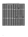
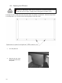
4.3.
Periodic check and inspection
The items listed below require periodic check and maintenance to retain the performance of the machine
and ensure safe operation:
Be sure to check annually to see if the power cords are damaged. The plug is
securely inserted and that there is no dust in the interior of the machine or
between the socket and the power cord. Using the product in an unclean condition
may cause a fire or electric shock.
Periodic checks should only be carried out by QUALIFIED SERVICE
PERSONNEL.
DESCRIPTION
WHAT TO CHECK
INTERVAL
HANDLE MECHA
Check the V.R. value
Monthly
Check adjust gear engagement
Every 3 months
Greasing of gears
Every 3 months
Check the V.R. value
Monthly
Check adjust gear engagement
Every 3 months
Greasing of gears
Every 3 months
Check SW
Monthly
Greasing
Every 3 months
Clean screen
Weekly
Check adjustment
Monthly
SEAT
Rail greasing
Monthly
GAME BD
Memory Test
Monthly
Game Assignments
Monthly
INTERIOR
Clean
Annually
POWER SUPPLY CORD
Check condition
Annually
CABINET SURFACE
Clean
As required
CONTROL PANEL
Lamp operation
Monthly
Check switch operation
Monthly
Clean
As required
Check sighting
Weekly
Check switch operation
Monthly
Check SW (If Fitted)
Monthly
ACCELERATOR & BRAKE
SHIFT LEVER
MONITOR / PROJECTOR
CONTROLLER (GUN)
COIN MECHANISM
39
5.
Game description
The following explanations apply to the product when functioning properly. If the product operates
differently from the following contents, a fault may have occurred.
Immediately look into and eliminate the cause of the fault to ensure proper operation.
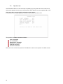
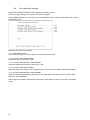
The fluorescent light in the billboard and the cold-cathode tube in the lighting unit are always on whenever
the power is turned on. Demo movies and game rankings are displayed on the screen.
Audio may also be played from speakers on the left and right sides of the projector. However, it is possible
to select whether sound is output or not during Attract Mode through Test Mode settings.
Both the right and left START buttons are integrated with a light. The light flashes when sufficient coins are
inserted for play. The light goes out when the START button is pressed to start the game.
Note: This image is not a true representation for the product. This image is for illustration purpose only.
40
5.1.
Game outline
Insert a coin and a credit will be added to the credit indicator below the screen. When enough coins
have been entered for one play, the "INSERT COIN(S)" message below the screen will change to
"PRESS START BUTTON," and both START buttons will flash.
NOTE: The maximum number of credits that can be counted at once is "24." Any coins inserted after 24
credits have been counted will not be counted as credits, nor will they be refunded. However, they will be
counted as inserted coins on the data display and by the coin meter.
A player plays on the left (Player 1) or the right (Player 2) by pressing the START button on that side.
Pressing the START button begins the game.
When the game starts, a demo plays and the stage title is displayed before switching over to game play.
Life, loaded bullets remaining and grenades are shown at the bottom left of the screen for the player on the
left (Player 1). Life, loaded bullets remaining and grenades are shown at the bottom right of the screen for
the player on the right (Player 2).
The gun holds 30 shots. When empty, the message "RELOAD" will appear on the screen.
The player can reload the gun by gently shaking it or by pointing it outside of the screen. Gently shaking it
or pointing it outside of the screen even if bullets remain in the gun can reload the gun.
Only the displayed number of grenades may be
used. This number may be increase by collecting
grenades during each stage. A maximum of 5
grenades may be held at once. Also, if only 2 or
less grenades remain upon clearing a stage, the
player will automatically start the next stage with 3
grenades.
41
Players can defend themselves against oil drums, rocks and axes thrown by enemies by shooting them.
Shooting the background will sometimes cause items to appear. Players grab them by shooting them.
Grabbing items will increase a player's score or restore life.
When life reaches zero the game ends.
A unique boss awaits the players at each stage. The bosses appear different on each stage.
Players defeat a boss by reducing its Life Meter to zero.
In addition, when a boss begins to attack the Cancel Meter appears. Players can stop the boss's attack by
reducing this meter to zero.
As the game progresses, players will be faced with enemies grabbing them and attempting to push them
over. To survive this danger, the player must shake the gun controller to fill up the on-screen meter within
the time limit. If the player fails to do so they will take damage, reducing their number of lives, and risk being
pushed over and taking further damage.
42
A player can join a game in progress at any time by inserting coins and pressing the START button. In
addition, the START button on the side where no one is playing will continue to flash if enough credits
remain. A second player can join the game by pressing the flashing START button.
"CONTINUE" is displayed when life drops to zero. A player may continue by inserting sufficient coins
and pressing the START button.
If upon clearing every stage in the game the player's score is better than the current top 10, they may
enter their name.
5.2.
Items
"Medical Kit"
Increases life by one.
"Mini Magician"
Increases a player's
score.
"Gold Coin"
Increases a player's
score.
"Golden Frog"
Increases a player's
score.
"Silk Hat"
Increases a player's
score.
"Toy's Bus"
Increases a player's
score.
Other items can also be found during the game.
43
5.3.
Play hints
Aim for the head!
Enemies in every stage, aside from boss characters, will lose the most life when shot in the head.
Therefore, shooting enemies accurately in the head is the fastest way to defeat them.
Choose your favorite route!
Each stage has a number of branching paths. Some branching paths can be simply chosen and
some depend upon certain actions. The key to improving play is to find the route that suits you
best!
Use recovery items to regain lost lives!
Although being attacked by enemies will reduce your remaining lives, each stage also contains
items that will increase remaining lives. Also, upon clearing a stage your performance may award
extra lives. Repeated play and knowledge of the levels will aid in gathering extra lives.
Use grenades effectively!
As well as the gun, you have grenades in your arsenal. These can cause massive damage to
enemies, and are best used when there are a large number of enemies on screen or at sections
you find difficult. Your number of remaining grenades can be increased by collecting items, and if a
stage is cleared with less than 2 grenades remaining you will start the next stage with 3.
Aim for the boss’ weak spot!
Every stage boss has a weak spot. Shooting this weak spot accurately will help you to avoid boss’
attacks. However, practice will be required to hit the weak spot accurately whilst the boss is moving.
44
6.
Maintenance instructions
6.1.
Explanation of test and display test
Use the switches on the VTS to enter the TEST MODE. This will allow you to carry out post installation and
periodic checks and adjustments. The following section details the function of each of the tests:
Be very careful about entering TEST MODE. If the machine you wish to test is
linked to other machines, exiting test on your machine will cause a network check
to be carried out. This will disable all other machines linked to it.
ITEM
DESCRIPTION
INTERVAL
When the machine is installed perform the following
checks:
INSTALLATION OF
THE MACHINE
• Check to see that each setting is as per the standard
settings input at the time of shipment.
• In the INPUT TEST mode, check each switch and
V.R.
Monthly
• In the OUTPUT TEST mode, check each of the lamps.
• In the MEMORY TEST mode check all of the IC’s on
the IC BD.
MEMORY
• On the TEST MENU screen choosing the MEMORY
TEST allows self test to be performed. In this test
RAM & ROM are tested.
Monthly
Periodically perform the following
• MEMORY TEST.
PERIODIC CHECKS
• Ascertain each setting.
Monthly
• In the INPUT TEST mode, test the control devices.
• In the OUTPUT TEST mode, check each of the lamps.
CONTROL SYSTEM
• In the INPUT TEST mode, check each switch and
V.R.
Monthly
• Adjust or replace each switch and V.R.
MONITOR
• In the C.R.T. TEST mode, check to ensure the monitor
is adjusted correctly
Monthly
• Clean screen (switch off machine and remove the
plug)
Weekly
MEMORY TEST
IC BOARD
DATA CHECK
EXTERIOR
MAINTENANCE
COIN MECHANISM
• In the SOUND TEST mode, check the sound related
ROMs
• Check such data as held in the bookkeeping screens,
relating to number and length of plays
Monthly
Monthly
• Clean surfaces
• Lubricate seat sliders
Monthly
Note: This appliance shall not be cleaned by a water jet.
• Check switch operation (if fitted)
Monthly
45
7.
System test mode
The SYSTEM TEST MODE allows the functioning of each part of the machine to be checked. In addition
game configuration and coin configuration changes can be made within this mode.
• When setting changes are made within TEST MODE, be sure to exit from TEST
MODE using the exit options. If you turn the power off and then on without having
exited correctly the changes you made will not take effect.
7.1.
System test menu
System Test Mode can be used to check the information or the operation of the LINDBERGH board,
adjust Monitor color, and perform coin/credit settings.
Press the TEST Button after powering on the unit to display the following SYSTEM TEST MENU.
Use the SERVICE Button to move the cursor to the desired test item. Press the TEST Button to enter
the selected item.
Press the TEST Button when GAME TEST MODE is selected to change to the Test Menu specific to
this game.
Refer to the section “GAME TEST MODE."
After the test is complete, move the cursor to EXIT and press the TEST Button to return to the Game
Advertisement screen.
46
7.2.
System information.
The SYSTEM INFORMATION screen displays system information.
The following information is displayed on this screen.
MOTHER BOARD
SERIAL NO.:
KERNEL VERSION:
BOOT VERSION:
REGION:
MEMORY SIZE:
STORAGE DEVICE:
The serial number of the game board.
The system's OS version.
The boot program version.
The region setting.
The onboard memory size.
The total capacity of the program installer device.
STORAGE SIZE:
The total capacity of the program installer device.
BASE BOARD
SERIAL NO.:
The serial number.
FIRM VERSION
The firmware version.
GRAPHIC BOARD
DEVICE ID:
The graphic board's ID.
Press the TEST Button to return to the System Test Menu screen.
47
7.3.
Storage information.
The STORAGE INFORMATION screen displays information on the game contained within the program
installer device. This screen is also used when uninstalling the game contained within the program installer
device.
Until preparations to launch the game are complete, a "now checking" screen will be displayed and uninstall
cannot be performed. If the program installer device does not contain any game data, the game information
will be displayed in grey and uninstall cannot be performed.
The following information is displayed on this screen.
GAME TITLE
GAME ID
PROGRAM TYPE
INSTALLED IMAGE LIST
IMAGE NUMBER
GAME IDVERSION
DATE OF RELEASE
Move the cursor to EXIT and press the TEST Button to return to the System Test Menu screen.
48
7.4.
JVS test.
The JVS TEST screen displays information on the connected JVS I/O boards.
Select INPUT TEST to display input data for the currently displayed JVS I/O board.
Select NEXT NODE to display information on the next NODE.
If no JVS I/O boards are connected, the message "NO JVS NODE" will be displayed.
The following information is displayed on this screen.
NODE:
NAME:
CMD VER:
JVS VER:
COM VER:
SWITCH:
COIN:
ANALOG:
ROTARY:
KEYCODE:
SCREEN:
CARD:
HOPPER OUT:
DRIVER OUT:
ANALOG OUT:
CHARACTER:
BACKUP:
The currently displayed NODE number and the total number of connected NODEs
ID Code
Command format version
JVS standard version
Communication version
Number of players and number of 1P switches
Number of coin slots
Number of analog channels
Number of encoders
Keycode input active/inactive
Screen position input (X axis, Y axis, number of channels)
Number of card slots
Number of hoppers
Number of standard output drivers
Number of analog output channels
Number of characters/lines displayed
Backup present/absent
Move the cursor to EXIT and press the TEST Button to return to the System Test Menu screen.
49
7.4.1. JVS input test.
Use the JVS INPUT TEST to test the JVS input.
The hexadecimal input information from the JVS I/O board will be displayed in real time.
The following information is displayed on this screen.
SYSTEM: System switch input data
PLAYER: Player number and player switch input data
COIN: Slot number and coin input data
ANALOG: Channel number and analog input data
Press the SERVICE and TEST Buttons simultaneously to return to the JVS Test screen.
50
7.5.
Monitor test
Use MONITOR TEST to check the output of the monitor.
Enter MONITOR TEST and the following color bars will be displayed.
Press the TEST Button and the screen will change to the following cross-hatch screen.
Press the TEST Button to return to the System Test Menu screen.
51
7.6.
Speaker test
Use SPEAKER TEST to check the output of speakers by having them each emit a test sound.
Select each speaker with the cursor and press the TEST Button to turn that speaker ON or OFF.
When set to ON a test sound will be emitted from that speaker.
It is possible to set multiple speakers to emit the test sound at the same time.
The speakers available to test are as follows.
RIGHT SPEAKER
LEFT SPEAKER
REAR RIGHT SPEAKER
REAR LEFT SPEAKER
CENTER SPEAKER
WOOFER SPEAKER
Move the cursor to EXIT and press the TEST Button to return to the System Test Menu screen.
52
7.7.
Coin assignments.
Use COIN ASSIGNMENTS to alter the credit settings.
The game will award players the number of credits determined here. Settings will only be saved if they have
been changed.
Changing the credit settings will also clear the current inserted coins value.
The following settings must be set as shown below for this product.
COIN CHUTE TYPE: COMMON
SERVICE TYPE: COMMON
The following information is displayed on this screen.
53
7.7.1. Coin chute type
COMMON:
Allow all credits to be used by all players.
INDIVIDUAL:
Treat each player's credits individually.
7.7.2. Service type
When the COIN CHUTE TYPE is set to COMMON, the number of credits available
to all players will increase by 1.
When the COIN CHUTE TYPE is set to INDIVIDUAL, each player's credits will
increase by 1.
When the COIN CHUTE TYPE is set to COMMON, the number of credits available
to all players will increase by 1.
When the COIN CHUTE TYPE is set to INDIVIDUAL, the player corresponding to
the SERVICE Button's credits will increase by 1.
COMMON:
INDIVIDUAL:
7.7.3. Coin chute #1 coin to credit rate. (Coin to credit conversion rate)
1 COIN(S) COUNT AS 1 CREDIT(S)
1 coin counts as 1 credit
2 COIN(S) COUNT AS 1 CREDIT(S)
2 coins count as 1 credit
3 COIN(S) COUNT AS 1 CREDIT(S)
3 coins count as 1 credit
4 COIN(S) COUNT AS 1 CREDIT(S)
4 coins count as 1 credit
5 COIN(S) COUNT AS 1 CREDIT(S)
5 coins count as 1 credit
1 COIN(S) COUNT AS 2 CREDIT(S)
1 coin counts as 2 credits
1 COIN(S) COUNT AS 3 CREDIT(S)
1 coin counts as 3 credits
1 COIN(S) COUNT AS 4 CREDIT(S)
1 coin counts as 4 credits
1 COIN(S) COUNT AS 5 CREDIT(S)
1 coin counts as 5 credits
FREE PLAY
Free play (no coins required)
DETAIL SETTING
More detailed settings
7.7.4. Coin chute #2 coin to credit rate. (Coin to credit conversion rate)
(Can only be set when the COIN CHUTE TYPE is set to COMMON and the COIN setting for the COIN
CHUTE #1 COIN TO CREDIT RATE is set to "1")
54
7.7.5. Detail settings.
The COIN ASSIGNMENTS DETAIL SETTING screen allows more detailed settings that cannot be
performed on the Coin Setting screen to be performed.
The following information is displayed on this screen.
COIN CHUTE #1 MULTIPLIER:
Coin conversion rate for #1 (How many coins 1
inserted coin counts for)
COIN CHUTE #2 MULTIPLIER:
Coin conversion rate for #2 (How many coins 1
inserted coin counts for)
BONUS ADDER:
Use of a bonus coin
NO BONUS ADDER
No bonus coin given
2 COINS GIVE 1 EXTRA COIN
2 coins inserted successively award 1 bonus coin
3 COINS GIVE 1 EXTRA COIN
3 coins inserted successively award 1 bonus coin
4 COINS GIVE 1 EXTRA COIN
4 coins inserted successively award 1 bonus coin
5 COINS GIVE 1 EXTRA COIN
5 coins inserted successively award 1 bonus coin
6 COINS GIVE 1 EXTRA COIN
6 coins inserted successively award 1 bonus coin
7 COINS GIVE 1 EXTRA COIN
7 coins inserted successively award 1 bonus coin
8 COINS GIVE 1 EXTRA COIN
8 coins inserted successively award 1 bonus coin
9 COINS GIVE 1 EXTRA COIN
9 coins inserted successively award 1 bonus coin
COIN TO CREDIT: The number of coins to number of credits conversion rate.
Move the cursor to EXIT and press the TEST Button to return to the Coin Assignments screen.
55
7.7.6. Game cost setting.
Use the COIN ASSIGNMENTS GAME COST SETTING screen to set the cost (number of required credits)
that the game program will use to determine if there are enough credits to play the game.
A total of 8 game costs can be defined. The BOOT ID defines the game cost, and when the second boot
recognizes the game, the game cost defined by the BOOT ID will be displayed.
If the game is not recognized, the default game cost will be displayed.
Move the cursor to EXIT and press the TEST Button to return to the Coin Assignments screen.
56
7.8.
Clock setting.
Use CLOCK SETTING to set the date and time.
Use the SERVICE Button to move the cursor to the category that you wish to change and press the TEST
Button to increase that value. Holding the TEST Button down will make the value continuously increase.
Changes will come into effect when you exit.
Move the cursor to EXIT and press the TEST Button to return to the System Test Menu screen.
57
7.9.
Network setting.
Use NETWORK SETTING to determine network settings or to test the network.
This product does not use the network function. You must use the following factory settings.
NETWORK TYPE: MAIN
MAIN NETWORK: No need to set.
The following information is displayed on this screen.
NETWORK TYPE: Sets the type of network to use.
MAIN NETWORK: Sets the onboard LAN.
NETWORK TEST: Performs a network test.
Move the cursor to EXIT and press the TEST Button to return to the System Test Menu screen.
58
Select a category on the NETWORK SETTING (Setting Menu) and the following screen will be
displayed. However, since this product does not use network function, this manual does not contain
instructions for performing network settings or tests.
NETWORK SETTING Screen
NETWORK TEST Screen
59
8.
Game test mode
Opens the Game Test Mode, allowing game specific settings and tests to be performed.
This option will be displayed in grey until preparations are complete. Select the Game Test Mode option
then perform the exit to begin the game test.
Among the settings in Game Test Mode, the following settings become effective as
listed below, rather than in the same way as System Test mode settings.
Changes in GAME ASSIGNMENTS are effective after selecting EXIT on the GAME
ASSIGNMENTS screen.
Changes in GUN CALIBRATION SETTING and GUN SPEED SETTING are effective
after pressing the TEST Button on the confirmation screen.
Game Test Mode allows game settings to be altered, Control Units (Guns) to be calibrated and game data
to be checked.
Select GAME TEST MODE from the System Test Menu screen to display the Game Test Mode screen as
follows.
Use the SERVICE Button to move the cursor to the desired test item. Press the TEST Button to enter the
selected item's test.
Performs test, adjustments and settings for each of the Game Test Mode screen items below.
a. INPUT TEST:
Tests each input device used in the game.
b. OUTPUT TEST:
Tests each output device used in the game.
c. GAME ASSIGNMENTS:
Adjusts game settings.
d. GUN CALIBRATION SETTING:
Performs sight settings for the game's gun.
e. GUN SPEED SETTING:
Sets the speed volume for the game's gun.
f. BOOKKEEPING:
View all recorded game data.
g. BACKUP DATA CLEAR:
Erase all game records.
60
After selecting an item, read the explanations below regarding operation.
After performing tests and adjustments, return to the Game Test Mode screen, select EXIT and press the
TEST Button. You will return to the System Test Menu screen.
Move the cursor to EXIT on System Test Menu screen and press the TEST Button to return to the Game
Play screen.
8.1.
Input test
Select INPUT TEST to display the following screen and check the status of input devices.
This test should be used periodically to check that each input device is functioning correctly.
The items refer to the following input devices. Input is normal if the display to the right of each item changes
from OFF to ON when each input device is operated.
Everything is functioning correctly if the GUN SPEED X and GUN SPEED Y values change according to the
speed at which the Control Unit (Gun) is moved vertically/horizontally.
Everything is functioning correctly if the word "OUT" to the right of SCREEN IN changes to "IN" when the
gun is pointed at the screen, and the values to the right of GUN X and GUN Y move between 00 to FF.
START:
The player START Buttons.
GUN TRIGGER:
The trigger on the gun.
GUN BUTTON:
The Button on the gun.
GUN SPEED X:
This value changes if gun is shaken on the X axis.
GUN SPEED Y:
This value changes if gun is shaken on the Y axis.
GUN X:
The X axis position on the screen targeted by the gun.
GUN Y:
The Y axis position on the screen targeted by the gun.
SCREEN IN:
Displays if the gun is pointing IN or OUT of the screen.
SERVICE:
The SERVICE Button.
TEST:
The TEST Button.
Press the SERVICE and TEST Buttons simultaneously to return to the Game Test Mode screen.
61
8.2.
Output test
Select OUTPUT TEST to display the following screen and check the status of output devices.
This test should be used periodically to check that the lamps are functioning correctly.
Use the SERVICE Button to move the cursor to the desired test item. Press the TEST Button to enter the
selected item's test.
Display of GUN MOTOR1 and GUN MOTOR2 options can be turned on or off using the
DIP-SW.
For cabinets with vibration motors attached to the Control Units (Guns), turn on display
of the GUN MOTOR1 and GUN MOTOR2 under DIP-SW settings to alter these settings.
Perform the tests as follows.
● START1 LAMP:
Select START1 LAMP and press the TEST Button to turn the option ON.
The player 1 START Button will light up. The lamp will remain on for as long as the
TEST Button is held down.
● START2 LAMP:
Select START2LAMP and press the TEST Button to turn the option ON.
The player 2 START Button will light up. The lamp will remain on for as long as the
TEST Button is held down.
● GUN MOTOR1:
Select GUN MOTOR1 and press the TEST Button to turn the option ON.
The player 1 gun will begin to vibrate. The vibration will continue for as long as the
TEST Button is held down.
● GUN MOTOR2:
Select GUN MOTOR2 and press the TEST Button to turn the option ON.
The player 2 gun will begin to vibrate. The vibration will continue for as long as the
TEST Button is held down.
Move the cursor to EXIT and press the TEST Button to return to the Game Test Mode screen.
62
8.3.
Game assignments
Select GAME ASSIGNMENTS to display the current game settings and make changes.
Changes to settings are not enabled until Game Assignments is exited. After changing settings, be sure to
exit the Test Mode.
Use the SERVICE Button to move the cursor to the desired test item. Press the TEST Button to enter the
selected item's test.
Perform the following settings for each item.
GAME DIFFICULTY:
Set the level of difficulty to one of five levels; VERY EASY -> MEDIUM EASY ->NORMAL -> MEDIUM
HARD -> VERY HARD.
LIFE SETTING INITIAL LIFE
The number of lives the player will start the game with. Can be set between 1 and 9.
However, cannot be set higher than the MAX LIFE setting.
LIFE SETTING MAX LIFE:
The maximum number of lives a player may have. Can be set between 1 and 9.
BLOOD COLOR:
You can set the color of blood to one of two settings; RED or BROWN.
VIOLENCE:
You can set the level of damage for the enemies to one of two settings; NORMAL or MILD.
When set to MILD, the violence of enemy deaths will be toned down.
ADVERTISE SOUND:
You can set the Attract Mode (Advertise) sound to ON or OFF.
After changing the settings, select EXIT and press the TEST Button to return to the Game Test Mode
screen.
63
8.4.
Gun calibration settings
Select GUN CALIBRATION SETTING to display the following screen.
Perform the sight settings for the guns to be used in the game.
Use the SERVICE Button to move the cursor to the desired test item. Press the TEST Button to enter the
selected item's test.
7.4.1
7.4.2
7.4.3
7.4.2
7.4.3
Details for each item are as follows.
7.4.1. GUN MARK CHECK:
Checks the gun sights. 1P and 2P guns are checked at the same time.
7.4.2. PLAYER1 GUN ADJUSTMENT:
Adjusts the sight for the Player 1 side.
7.4.3. PLAYER1 GUN DEFAULT ADJUSTMENT:
Adjust the default sight settings for the Player 1 side.
7.4.2. PLAYER2 GUN ADJUSTMENT:
Adjust the sight for the Player 2 side. (Operated in the same way as PLAYER1 GUN ADJUSTMENT)
7.4.3. PLAYER2 GUN DEFAULT ADJUSTMENT:
Adjust the default sight settings for the Player 2 side. (Operated in the same way as PLAYER1 GUN
DEFAULT ADJUSTMENT)
After changing the settings, select EXIT and press the TEST Button to return to the Game Test Mode
screen.
64
8.4.1. Gun mark check
This checks gun sights.
Select GUN MARK CHECK on the Gun Calibration Setting screen and press the TEST Button.
1P Gun Cross
This is displayed when the gun is pointed at the screen. 1P is red.
2P Gun Cross
This is displayed when the gun is pointed at the screen. 2P is blue.
"OUT OF SCREEN" is displayed when the gun cross is perceived to be out of screen.
Pointing the gun at the screen displays the gun cross (sight) for that gun. You can check to see if the sight
lines up properly at this screen.
Press the TEST Button when everything has been checked. You will return to the Gun
Calibration Setting screen.
65
8.4.2. Gun adjustment
This item adjusts the Player 1 gun sight. (This is the same for "PLAYER2 GUN ADJUSTMENT".)
Select PLAYER1 GUN ADJUSTMENT on the Gun Calibration Setting screen and press the TEST Button.
NOTE: "PLEASE SHOOT GRID WITH PLAYER1 GUN" on the screen will flash.
Follow the on-screen instructions to adjust the gun sight settings. Aim at the mark in the upper left corner
and fire. The mark in the upper left will disappear, and the same mark will be displayed in the lower right
corner.
(Press the TEST Button to return to the Gun Calibration Setting screen with canceling the adjustment.)
66
Aim and fire at the mark to the lower right. The mark to the lower right will disappear, and the same mark
will be displayed in the center.
(Press the TEST Button to return to the Gun Calibration Setting screen.)
Aim and fire at the mark in the center.
"NOW CALCULATING" will be displayed in the center. The screen will automatically switch to the following.
67
Point the Control Unit (Gun) at the screen and a gun mark will be displayed. Check to make sure that the
gun can aim right up to the edges of the frame.
If the calibration is correct press the TEST Button to save it.
If re-calibration is required press the SERVICE Button. The calibration results will not be saved and you will
return to the Gun Calibration Setting screen.
"OUT OF SCREEN" is displayed when the gun cross is perceived to be out of screen.
Refer to the following procedure when adjusting the sights.
Line up the concave sight nearest you on the gun so that it is at the height of the horizontal line of the "+"
mark.
Line up the convex sight at the tip of the gun so that it also lines up with the horizontal line.
Line up the centers of the tops of the concave and convex sights with the center of the "+" and fire.
68
8.4.3. Gun default adjustment
This item adjusts the sight settings to those at the time of shipment.
(This is the same for"PLAYER2 GUN DEFAULT ADJUSTMENT".)
Select PLAYER 1 GUN DEFAULT ADJUSTMENT on the Gun Calibration Setting screen and press the
TEST Button.
Press the TEST Button to set the Control Unit (Gun) targeting to the pre-set default values.
When setting is complete the message "COMPLETED" will appear on the screen and it will then
automatically proceed to the Gun Calibration Setting screen.
If you wish to cancel this process, press the SERVICE Button. The screen will automatically proceed to the
Gun Calibration Setting screen without altering the settings for the gun.
69
8.5.
Gun speed setting
Adjust the volume settings for the Control Unit's (Gun's) speed sensors.
Select GUN SPEED SETTING on the Game Test Mode screen and press the TEST Button to display the
following screen.
Use the SERVICE Button to move the cursor to the desired test item.
Press the TEST Button to enter the selected item's test.
7.5.1
7.5.2
7.5.3
7.5.2
7.5.3
Details for each item are as follows.
7.5.1. GUN SPEED CHECK:
Checks the registered speed when the guns are shaken. Player 1 and Player 2 Guns are both checked
together.
7.5.2. PLAYER1 GUN SPEED ADJUSTMENT:
Adjusts the registered speed for when the Player 1 gun is shaken.
7.5.3. PLAYER1 GUN SPEED DEFAULT ADJUSTMENT:
Returns the registered speed for when the Player 1 gun is shaken to the pre-set default setting.
7.5.2. PLAYER2 GUN SPEED ADJUSTMENT:
Adjusts the registered speed for when the Player 2 gun is shaken. (Operated in the same way as PLAYER1
GUN SPEED ADJUSTMENT.)
7.5.3. PLAYER2 GUN SPEED DEFAULT ADJUSTMENT:
Returns the registered speed for when the Player 2 gun is shaken to the pre-set default setting. (Operated
in the same way as PLAYER1 GUN SPEED DEFAULT
ADJUSTMENT.)
After changing the settings, select EXIT and press the TEST Button to return to the Game Test Mode
screen.
70
8.5.1. Gun speed check
Checks the registered speed when the Control Units (Guns) are shaken.
Select GUN SPEED CHECK on the Gun Speed Setting screen and press the TEST Button to display the
following screen.
Moving the gun for each player will alter the values displayed on the X axis and Y-axis speed bars. Use this
screen to check that the current maximum speed setting matches the speed values by moving the guns
around.
If the numbers don't change at all:
The sensors may be broken or cables disconnected.
If the numbers change but never reach even half of the MAX value no matter how hard the gun is moved:
There is a problem with speed settings.
Once you have finished all checks press the TEST Button to return to the Gun Speed Setting screen.
71
8.5.2. Player 1 & Player 2 gun speed adjustment
Pay attention to your surroundings when moving the Control Unit (Gun) during speed
adjustment so as not to hit people or objects around you.
You may hurt others or yourself if due caution is not taken.
If GUN SPEED SETTINGS are not set, or a mistake is made with the GUN SPEED
SETTINGS, the gun may start to only fire single shots during the game.
This is because the gun continually registers as having been shaken and thus
continually reloads. This is not a fault with the gun itself, and can be fixed by
performing GUN SPEED SETTINGS again.
Adjusts the registered speed for when the Player 1 gun is shaken. (This is the same for "PLAYER2 GUN
SPEED ADJUSTMENT".)
Select PLAYER1 GUN SPEED ADJUSTMENT on the Gun Speed Setting screen and press the
TEST Button to display the following screen.
NOTE: "PLEASE SHAKE THE PLAYER1 GUN" on the screen will flash.
Follow the onscreen instructions to perform the gun speed settings.
Shake the gun on the X-axis and the Y-axis and set the MAX value for each.
NOTES:
You need only shake the gun gently on the X-axis and the Y-axis. If these settings are set with the gun
shaken very hard it may lead to malfunctions during the game.
Proceed to the next screen to confirm the set values. The bar here is simply for reference, and swinging
the gun forcefully and filling this bar to the top is not necessary. Moving the gun lightly so that the bar is
more than half full will allow the game to progress smoothly.
72
Press the TEST Button and the message "NOW CALCULATING" will be displayed on the screen, and it will
then proceed automatically to the next screen.
The set MAX speed values will be displayed. Move the gun again and check that these are no problems
with these speed settings. If everything seems in order, press the TEST Button.
If the speed settings need to be adjusted again, press the SERVICE Button. The results of the adjustment
will not be saved and the screen will return to the Gun Speed Setting screen.
Press the TEST Button and the message "COMPLETED" will be displayed on the screen, and it will then
proceed automatically to the Gun Speed Setting screen.
73
8.5.3. Player 1 & Player 2 gun speed default adjustment
Returns the speed setting to the default factory setting.
(This is the same for "PLAYER2 GUN SPEED DEFAULT ADJUSTMENT".)
Select PLAYER1 GUN SPEED DEFAULT ADJUSTMENT on the Gun Speed Setting screen and press the
TEST Button to display the following screen.
Press the TEST Button to set the Control Unit (Gun) speed settings to the pre-set defaults. If you wish to
cancel the process, press the SERVICE Button.
The gun speed settings will not be changed and the screen will automatically return to the Gun Speed
Setting screen.
When adjustment is complete the message "COMPLETED" will be displayed on the screen and it will then
proceed automatically to the Gun Speed Setting screen.
74
8.6.
Bookkeeping
Select BOOKKEEPING on the Game Test Mode screen to display the three screens of operating status
data.
The display items for the screen (PAGE 1/3) are as follows.
● COIN 1:
The number of coins inserted into Coin Chute 1.
● COIN 2:
The number of coins inserted into Coin Chute 2.
● TOTAL COINS:
The total number of coins inserted into the coin
chutes.
● COIN CREDITS:
The number of credits for the coins inserted.
● SERVICE CREDITS: ●
TOTAL CREDITS:
The number of credits input by the SERVICE Button.
The total number of all credits.
Press the TEST Button to display the next screen (PAGE 2/3).
75
The display items for the screen (PAGE 2/3) are as follows.
● NUMBER OF GAMES:
● FIRST PLAY:
● CONTINUE PLAY:
The total number of games played by 1P and 2P.
The total number of games started by 1P and 2P.
● PLAY TIME:
The total number of continues used by 1P and 2P.
The amount of time the unit has been in
operation.
The amount of time the game has been played.
● AVERAGE PLAY TIME:
The average play time for one game.
● LONGEST PLAY TIME:
The longest play time for one game.
● SHORTEST PLAY TIME:
The shortest play time for one game.
● TOTAL TIME:
Press the TEST Button to display the next screen (PAGE 3/3).
This displays play times on a scale from 0M00S to 9M59S with 30-second intervals.
All play times over ten minutes are included in the item OVER 10M00S.
Press the TEST Button after viewing. You will return to the Game Test Mode screen.
76
8.7.
Backup data clear
Select BACKUP DATA CLEAR to clear the contents of BOOKKEEPING in the Game Test
Mode and the game score.
To clear data, use the SERVICE Button to move the cursor to YES (CLEAR) and then press the TEST
Button.
When the data has been cleared, the message "COMPLETED" will be displayed and the screen will return
to the Game Test Mode screen automatically.
Move the cursor to NO (CANCEL) and press the TEST Button to return to the Game Test Mode screen
without clearing the data.
77
9.
Gun control unit
In order to prevent any electric shocks or short circuits, be sure to turn the power off
before performing any work that involves touching the interior parts of the product.
Be careful not to damage the wires. Damaged wires may cause electric shocks or
short circuits, or present a risk of fire.
Be very careful when soldering. Handling a soldering iron carelessly may result in a
fire or burns.
When securing the plastic-made parts, do not excessively fasten screws and nuts.
Failure to do this may damage the parts, and fragments resulting from damage may
cause injury.
When reassembling the Control Unit (Gun), be sure to check the connecting portion
and the trigger, etc. If the reassembly work is insufficient and/or incorrect, fingers
may be caught and result in injury.
Make sure that there is no gap when attaching cover L and R. A gap or crack may
trap hands or fingers and lead to injury.
Do not cut the tie belt securing the wires in the Control Unit (Gun).
Cutting the tie belt may cause malfunctioning of the wire connection. If you cut the tie
belt when replacing the wire etc., be sure to secure the wires using a new tie belt as
before.
After taking the Control Unit (Gun) apart, always use "Tightening Adhesive" (part
number: 090-0012). Apply an appropriate amount to the screw and then tighten it up.
If you do not use "Tightening Adhesive" there is a risk of looseness or the Control
Unit (Gun) coming apart.
Only use the tightening adhesive specified by this manual. Using any other
"Tightening Adhesive" may cause a chemical reaction that renders the screws
useless or damage the surface of the Control Unit (Gun).
Follow these directions carefully to avoid damaging or losing small parts.
After exchanging any parts, always enter Test Mode and adjust/check the Control
Unit (Gun).
78
If there appears to be a problem with the gun and adjustment in Test Mode makes no difference, part of the
gun is most likely broken.
Use the following instructions to take the gun apart and replace the broken part.
The exterior casing, comprised of cover L and cover R, must be opened up in order to change interior parts.
As some internal parts are connected to cover R, work with cover R face down on the working surface.
79
9.1.
Replacing the microswitch
The Control Unit (Gun) houses two microswitches, the trigger microswitch and the grenadebutton
microswitch.
Turn off power to the cabinet.
Removing all 9 screws will allow cover L and
cover R to be taken apart. Remove all 9
screws.
SCREW (9), black
M3×12, w/small flat & spring washers
Place cover R face down on the work surface
and slowly lift cover L directly upward.
Lift the trigger microswitch up from where it is
attached to cover R.
80
Remove the solder, allowing you to remove
the microswitch.
The grenade button microswitch is located at
the base of the grenade button. Lift the
grenade button free of cover R.
Remove the screw and remove microswitch cover R.
Undo the brackets and remove the solder to allow
you to remove the microswitch.
Solder the new microswitch in place on the gun.
Then operate all buttons on the gun and confirm that the microswitch turns ON/OFF before putting covers
L and R back together.
Do not tighten the screws too tightly when reattaching the covers.
Perform an input test as described in the chapter on "Test Mode."
81
9.2.
Replacing the sensor unit
① Follow steps ① - ③ above of the microswitch replacement procedure.
You will now have removed cover L.
② Undo the connector and remove the
sensor unit.
Undo the connector.
③ Attach the new sensor unit and fit it back in place inside the Control Unit (Gun).
Then operate all buttons on the gun and confirm that the microswitch turns ON/OFF before putting covers L
and R back together.
Do not tighten the screws too tightly when reattaching the covers.
④ Perform a targeting test as described in the chapter on "Test Mode."
82
9.3.
Replacing the speed sensor unit
① Follow steps ① - ③ above of the microswitch replacement procedure.
You will now have removed cover L.
② Remove 1 screw.
SCREW (1), black
M3×6, w/spring washer
③ Remove cover R from the speed sensor
and undo the connector.
Undo the connector.
④ Undo the 2 screws and separate the sensor (board) and brackets. The brackets, screws and plastic
washers will be used with the new sensor so do not lose them.
⑤ Replace the sensor and paying careful attention to all parts involved place it inside the gun.
Pass the screws through the sensor, plastic washers and then the bracket in order.
⑥ Perform a speed test as described in the chapter on "Test Mode."
83
10.
Projector
The projector is adjusted prior to leaving the factory. Avoid any unnecessary
adjustment.
If the adjustment method in this manual does not resolve the problem contact the
customer service number in this manual or your supplier.
"Snow" on the screen/changes in brightness for a short period is due to the highpressure mercury lamp in the projector. This is not a defect and does not need
repairs.
The life of the high-pressure mercury lamp is the average number of hours 50% of
lamps last for. Therefore a life of 8,000 hours does not mean that the lamp cannot
last beyond 8,000 hours.
There is no way of knowing when the lamp is going to cease to function. Once it
ceases to function, the projector will be unable to display anything and the product
cannot be used. Have a spare lamp ready at all times.
Do not stick tape, stickers or anything else onto the screen. Any kind of adhesive
may damage the surface of the screen.
The projector remembers adjustments.
If there is any distortion, etc. that requires adjustment on the TEST screen, use the remote control.
The average life of the projector's high pressure mercury lamp is approximately 8000 (50% survival), but
the its actual lifespan depends on how it is used etc.
The lamp will not last forever. If the screen is dark or continually disappears the lamp must be changed
immediately.
Follow the procedure as outlined in the projector manual to change the lamp and be sure to reset the timer
setting.
84
10.1. Cleaning the screen
Since the Projector screen is susceptible to damage, pay careful attention to its
handling. When cleaning, refrain from using water or volatile chemicals.
When the screen surface becomes dirty with dust, etc., clean it by using a soft cloth such as gauze. When
water, and volatile chemicals such as benzene, thinner, etc., spill on the screen surface, it may be subject
to damage, therefore, do not use them.
Also, since the surfaces are susceptible to damage, refrain from rubbing them with a hard material or using
a duster.
If the screen is especially dirty, call in a professional cleaner.
85
10.2. Projector adjustment
When making adjustments, make sure that the remote control's emitter is pointed
toward the projector screen.
The projector unit itself does not have any controls on it.
*1: Do not needlessly enter SERVICE or SPECIAL Modes. Any control errors made
in these Modes may alter settings and prevent display. This manual does not
contain an explanation of SERVICE Mode.
*2: The projector does not have a VIDEO input. The VIDEO setting cannot be used.
Use the accompanying remote control to perform all projector adjustments.
The remote control cannot turn the projector or the entire game system's power ON or OFF.
86
ADJUST (ADJUST Mode):
Press this button to enter ADJUST Mode. It
also functions as the EXIT button.
W/B switch (white balance):
Select WHITE BALANCE Mode.
WRITING (memory):
Store adjustment data.
R, G, B (color select):
Use to select a color when adjusting color
balance.
CONTRAST:
Adjust the contrast of the projected image.
BRIGHT:
Adjust the black level (brightness) of the
projected image.
TP (test pattern):
Display an internal test pattern.
PHASE (phase adjust):
Adjust the sampling phase.
CLOCK (clock adjust):
Adjust the sampling clock.
POSI (display position):
Adjust the display position of the projected
image.
CAPTURE (adjust image capture):
Adjust timing of image capture.
VIDEO input:
Select video input.
RGB input:
Select RGB input.
DVI input:
Select DVI input.
*1 SERVICE:
Enter SERVICE Mode.
CUT OFF (adjust cut off):
Adjust the white balance of dark areas.
ADJUST (adjust up/down and left/right): Adjusted selected category.
*1 SPECIAL:
Enter SPECIAL Mode.
DRIVE (adjust drive):
Adjust the white balance of light areas.
87
10.3. Colour adjustment
The projector is precisely adjusted in the factory prior to sale. Avoid unnecessary
adjustment at all costs. Needlessly altering adjustment data may make any later
repairs harder to perform.
Before performing any adjustments you must first press the ADJUST button and enter ADJUST Mode. If
you wish to exit without making any adjustments press the ADJUST button twice to return to Normal
Mode.
Once in ADJUST Mode press the button for the adjustment you wish to make.
When the adjustment category is displayed used the ADJUST [▲ ] [▼ ] [ ] [ ] buttons to make adjustments.
When you have finished making adjustments press the WRITING button to record the adjusted data. If
you wish to exit without saving the adjusted data return to Normal Mode without pressing the WRITING
button and then turn the power off for a reasonable period of time. Press the ADJUST button three times
to return to Normal Mode.
88
10.4. Adjusting contrast
To abort adjustment without recording any changes press the ADJUST button
twice (in some instances three times) to return to Normal Mode.
If you wish to carry on and make further adjustments to a different menu repeat 2
~ 3.
If you do not record adjustment data then all adjustments will be lost when the
power if turned off, and when it is turned back on the projector will be returned to
the state prior to adjustment.
Adjusting the contrast will alter the tones of the displayed image.
89
10.5. Adjusting brightness
To abort adjustment without recording any changes press the ADJUST button twice
(in some instances three times) to return to Normal Mode.
If you wish to carry on and make further adjustments to a different menu repeat 2 ~ 3.
If you do not record adjustment data then all adjustments will be lost when the power if
turned off, and when it is turned back on the projector will be returned to the state prior
to adjustment.
Mistaken adjustment of the brightness can reduce the quality of the projected image. It
is therefore recommended that the factory setting by used.
Adjusting the brightness will alter the display of the black parts of the image.
90
10.6. Adjusting cut-off
To abort adjustment without recording any changes press the ADJUST button twice (in
some instances three times) to return to Normal Mode.
If you wish to carry on and make further adjustments to a different menu repeat 2 ~ 3.
If you do not record adjustment data then all adjustments will be lost when the power if
turned off, and when it is turned back on the projector will be returned to the state prior
to adjustment.
Mistaken adjustment of the cut off can reduce the quality of the projected image. It is
therefore recommended that the factory setting by used.
91
10.7. Adjusting drive
To abort adjustment without recording any changes press the ADJUST button twice
(in some instances three times) to return to Normal Mode.
If you wish to carry on and make further adjustments to a different menu repeat 2 ~ 3.
If you do not record adjustment data then all adjustments will be lost when the power if
turned off, and when it is turned back on the projector will be returned to the state prior
to adjustment.
Mistaken adjustment of the drive can reduce the quality of the projected image. It is
therefore recommended that the factory setting by used.
Adjusting the drive will alter the white balance of the light parts of the image.
92
10.8. Adjusting screen display position
To abort adjustment without recording any changes press the ADJUST button twice
(in some instances three times) to return to Normal Mode.
If you wish to carry on and make further adjustments to a different menu repeat 2 ~ 3.
If you do not record adjustment data then all adjustments will be lost when the power if
turned off, and when it is turned back on the projector will be returned to the state prior
to adjustment.
93
10.9. Adjusting capture
To abort adjustment without recording any changes press the ADJUST button twice
(in some instances three times) to return to Normal Mode.
If you wish to carry on and make further adjustments to a different menu repeat 2 ~ 3.
If you do not record adjustment data then all adjustments will be lost when the power if
turned off, and when it is turned back on the projector will be returned to the state prior
to adjustment.
94
10.10. Adjusting the clock
To abort adjustment without recording any changes press the ADJUST button twice
(in some instances three times) to return to Normal Mode.
If you wish to carry on and make further adjustments to a different menu repeat 2 ~ 3.
If you do not record adjustment data then all adjustments will be lost when the power if
turned off, and when it is turned back on the projector will be returned to the state prior
to adjustment.
Mistaken adjustment of the drive can reduce the quality of the projected image. It is
therefore recommended that the factory setting by used.
95
10.11. Adjusting phase
To abort adjustment without recording any changes press the ADJUST button twice
(in some instances three times) to return to Normal Mode.
If you wish to carry on and make further adjustments to a different menu repeat 2 ~ 3.
If you do not record adjustment data then all adjustments will be lost when the power if
turned off, and when it is turned back on the projector will be returned to the state prior
to adjustment.
Mistaken adjustment of the drive can reduce the quality of the projected image. It is
therefore recommended that the factory setting by used.
96
10.12. White balance switch
WB1 has been given standard adjustment in the factory. Therefore use of WB1 is
recommended.
White balance (W/B) is adjusted (preset) to WB1 in the factory, but you can switch it to suit your needs.
97
10.13. Change input (RGB input / DVI input)
You must use the analog RGB setting with this product.
If the input selected in change input is not receiving a signal the message "NO INPUT
SIGNAL" will be displayed for approximately 5 seconds on the screen. After that the
screen will remain black.
The projector can be switched between analog RGB input and DVI input.
98
10.14. Display internal test pattern
The projector has the following internal test pattern onboard.
However, to adjust the monitor for this product you must use MONITOR TEST under TEST Mode.
99
10.15. Display internal test pattern
100
10.16. Special mode: Lamp, timer display and reset
After changing the lamp you must perform the lamp reset operation (step 4 below) to
reset the lamp timer.
Displays the amount of time the lamp has been used for.
101
102
10.17. Special mode: Force mode.
You must set FORCE Mode to OFF for this product.
To abort adjustment without recording any changes press the ADJUST button twice
(in some instances three times) to return to Normal Mode.
Setting FORCE Mode to ON will allow you to set reception to always occur with the same timing.
When FORCE Mode is set to OFF reception will be set automatically each time in accordance with a timing
signal. However, if this does not match the timing signal recorded in the projector, the image may fall out of
sync.
103
10.18. Special mode: Auto adjust and frame lock setting.
You must set AUTO ADJUST Mode to ON for this product.
You must set Frame Lock to ON for this product.
To abort adjustment without recording any changes press the ADJUST button twice
(in some instances three times) to return to Normal Mode.
AUTO ADJUST ON/OFF (Press the PHASE button at step 3)
Setting the AUTO ADJUST Mode to ON will automatically determine the timing signal and the image will be
displayed in the normal screen position.
Setting AUTO ADJUST Mode to OFF will display the image according to the timing signal recorded in the
projector.
FRAME LOCK ON/OFF (Press the POSI button at step 3)
If Frame Lock is set to OFF then "snow" may appear on the screen when displaying moving images. If this
happens setting the Frame Lock to ON is advised.
104
10.19. Special mode: Re-auto adjust.
To abort adjustment without recording any changes press the ADJUST button twice (in
some instances three times) to return to Normal Mode.
RE-AUTO ADJUST (Press the VIDEO button at step 3)
Press this button and the Auto Adjust process will be performed again.
If the image is being drawn incorrectly pressing this button should fix the problem.
You must input a signal that displays 100% of the image field when performing this operation.
For this product, use the MONITOR TEST screen under TEST Mode.
105
10.20. Changing the lamp unit.
To prevent electric shock and fire hazards, only perform this operation after turning
off the main power switch and removing the power cord from the socket.
Never put anything metal or flammable into the interior of the DLP.
Using it with such an object inside may lead to an electric shock or fire.
Make sure that the lamp is firmly in place. If the lamp is loose then it is a fire hazard,
and it also might not come on.
The lamp becomes very hot during use and remains so for a while afterward.
Attempting to change the lamp before it has sufficiently cooled may lead to burns and
other injuries.
If the lamp shatters fragments of glass will remain inside the lamp.
Never shake a shattered lamp or hold/place one higher than eye level.
Doing so could lead to a serious accident.
When opening the door or lamp cover to change the lamp, do not touch or remove any
parts that are unrelated to the lamp changing process. Doing so may lead to injury, and
could also harm the efficient working of the product.
Do not remove any screws other than those specified below. Doing socould harm the
efficient working of the product.
Always perform the lamp changing operation with the power turned off.
Once you have inserted the new lamp only turn the power back on once the lamp exchange cover is back
in place. Then enter SPECIAL mode and reset the lamp timer on the Lamp Timer Screen.
106
Turn OFF the main power switch on the AC unit and disconnect the power.
Remove the 4 truss screws and remove the front panel.
Remove the 4 screws and remove the lamp change cover.
Remove the old lamp unit. Loosen the three screws holding the lamp unit in place.
Pull the lamp out toward you.
107
Insert the new lamp unit. Make sure that you push it all the way in.
Tighten the three screws to hold the lamp unit in place.
Replace the lamp change cover and fix it in place with the 4 screws.
Replace the front panel and fix it in place with the 4 truss screws.
108
11.
Coin validator.
When working with the product, be sure to turn the power off. Working with the power
on may cause an electric shock or short circuit.
Be careful not to damage the wires. Damaged wires may cause electric shocks or
short circuits, or present a risk of fire.
11.1.1.VTS P.C board.
All playable credit for this machine is controlled by the VTS board.
This electronic circuit allows the price of play to be set for a range of different countries.
These functions are set on Dual In Line (DIL) PCB mounted switches.
DIL-2 is used to set the currency (or coin ratio) and DIL-1 the price of play.
Refer to the Tables on the following pages for the correct settings for your environment.
The VTS board pictured below is mounted on the VTS Bracket within the Coin Tower.
The VTS board is connected to the coin validator and lamps via a dedicated wiring harness depending
upon the coin validator used:
Wiring Harness
Validator
LM1006
Coin Controls
(15 way connector)
LM1007
Mars
(13 way connector)
LM1008
Mechanical
See note 1
N/A
NRI
See note 2
Mechanical coin mechanisms may be connected in parallel allowing two identical mechanisms to be fitted.
If NRI mechanisms are to be used, these should be ordered (programmed) with the highest denomination
coin on coin-path #1 and the lowest denomination on coin-path #4. The VTS board should be then be set
up for either the UK or EURO settings. A minimum connecting lead length of 600mm is required.
All COIN ASSIGNMENTS are carried out and processed by the VTS Board. This game uses a single SR3
Coin Validator (if supplied). This Validator will connect into port A as indicated by the illustration above.
109
11.1.2. CREDIT SETTINGS
The CREDIT SETTINGS as displayed in the COIN ASSIGNEMNTS of the SYSTEM
TEST MODE in the LINDBERGH TEST MENU should always be set to 1 COIN = 1
CREDIT to maintain a correct output from the VTS.
110
11.1.3.VTS credit board option settings
Country
UK
UK
UK
Setting
Switch 3 Setting
SW1 SW2 SW3 SW4 SW5 SW6
Coin Controls OFF OFF OFF OFF
C220 Parallel
Coin Controls
C220 Binary
Coin Controls
C220 Binary
Credit Board Mode Settings Switch 3
Coin Validator Programming
COIN1 COIN2
COIN3
COIN4 COIN5 COIN6
£1
50p new
20p
10p
50p old
COIN7
-
COIN8
-
ON
OFF
OFF
OFF
£1
50p new
20p
10p
-
50p old
-
£2
OFF
ON
OFF
OFF
£1
50p new
20p
10p
-
£2
-
-
£2
-
-
-
-
-
-
50p
old
50p
old
-
50p old
-
-
-
-
50Pta
old
25Pta
old
-
UK
Coin Controls
SR3 Parallel
ON
ON
OFF
OFF
£1
50p new
20p
10p
UK
Euro
UK
Coin Controls
SR3 Parallel
OFF
OFF
ON
OFF
Mars ME/MS
111 Parallel
NRI Parallel
UK
Parallel
Belgium
Parallel
Holland
Austria SR3 Parallel
Spain Coin Controls
C220 Binary
ON
OFF
ON
OFF
£2
€2
£1
£1
€1
£2
50p new
50¢
20p
20p
20¢
10p
OFF
ON
OFF
ON
OFF
ON
ON
OFF
OFF
ON
ON
ON
OFF
OFF
OFF
OFF
OFF
ON
ON
ON
10p
20Sch
500Pta
20p
50BFr
5NLG
10Sch
200Pta
50p
20BFr
2.5NLG
5Sch
100Pta
£1
5BFr
1NLG
1Sch
50Pta
£2
-
25Pta
200Pt
old
-
50Pta
old
-
25Pta
old
200Pta
50Pta
old
-
-
25Pta
old
-
10p
10¢
50p new 50p old
Spain
SR3/NRI
Parallel
ON
ON
OFF
ON
500Pta
200Pta
100Pta
50Pta
25Pta
Spain
Coin Controls
C220 Parallel
OFF
OFF
ON
ON
100Pta
-
Parallel
ON
OFF
ON
ON
200Es
€1
TBA
25Pta
new
-
-
Portugal
Euro
50Pta
new
100Es
50¢
TBA
OFF
ON
Channels
C120/SR3 Only
COIN9 COIN10 COIN11 COIN12
50Es
-
-
Please Note
The credit board automatically sets the validator for parallel and binary
operation through an output on pin 8 of the 17 way pinstrip. For the feature
to work it is necessary for the validator interconnecting cable to include at
wire at this position
TBA
OFF Direct Mode
ON 2 channel Mode
Note: These switch settings are under constant review and may change due to world currency updates.
•
Set SW 1 according to the option settings found in the relevant Price of Play Settings Table on the following pages.
•
For Germany (DM), France (Fr) & Switzerland (SFr), use the appropriate existing setting shown above (from another country) that matches the coin ratios programmed into your coin mech.
•
Set SW 3 on the VTS /Excel board as shown in the table above corresponding to the country required.
111
11.1.4.VTS credit board price of play settings (Sterling).
Price
Bonus
DIL Switch 1
1
2
3
4
5
6
7
8
9
10
11
12
13
14
15
16
17
18
19
20
21
22
23
24
25
26
27
28
29
30
31
32
10p
No Bonus
10p
6 = 50p
20p
No Bonus
20p
3 = 50p
6 = £1
30p
No Bonus
30p
1.66 = 50p
4 = £1
30p
2 = 50p
4 = £1
30p
AMLD *
3 = £1
40p
No Bonus
40p
1.25 = 50p
3 = £1
50p
No Bonus
50p
3 = £1
50p
2 = £1
60p
No Bonus
60p
2 = £1
80p
No Bonus
80p
1.25 = £1 2 = £1.50
£1
No Bonus
£1
3 = £2
£1
2 = £2
£1.50
No Bonus
£1.50
2 = £2
£2
No Bonus
£2
£3
No Bonus
£3
£5
No Bonus
£5
£7.50
No Bonus
£7.50
£10
No Bonus
Free Play
12 =£2
8 = £2
6 = £2
6 = £2
6 = £2
5 = £2
4 = £2
2.5 = £2
5 = £4
3 = £5
2 = £5
3 = £10
2 = £10
Switch 1 Switch 2 Switch 3 Switch 4 Switch 5
OFF
OFF
OFF
OFF
OFF
OFF
OFF
OFF
OFF
ON
OFF
OFF
OFF
OFF
ON
OFF
OFF
OFF
ON
ON
OFF
OFF
OFF
OFF
ON
OFF
OFF
OFF
ON
ON
OFF
OFF
OFF
ON
ON
OFF
OFF
ON
ON
ON
OFF
OFF
OFF
OFF
ON
OFF
OFF
OFF
ON
ON
OFF
OFF
OFF
ON
ON
OFF
OFF
ON
ON
ON
OFF
OFF
OFF
ON
ON
OFF
OFF
ON
ON
ON
OFF
OFF
ON
ON
ON
OFF
ON
ON
ON
ON
OFF
OFF
OFF
OFF
ON
OFF
OFF
OFF
ON
ON
OFF
OFF
OFF
ON
ON
OFF
OFF
ON
ON
ON
OFF
OFF
OFF
ON
ON
OFF
OFF
ON
ON
ON
OFF
OFF
ON
ON
ON
OFF
ON
ON
ON
ON
OFF
OFF
OFF
ON
ON
OFF
OFF
ON
ON
ON
OFF
OFF
ON
ON
ON
OFF
ON
ON
ON
ON
OFF
OFF
ON
ON
ON
ON
OFF
ON
OFF
ON
ON
ON
ON
ON
ON
ON
ON
ON
ON
ON
112
11.1.5.VTS credit board rice of play settings (EURO).
Price
Bonus
DIL Switch 1
1
2
3
4
5
6
7
8
9
10
11
12
13
14
15
16
17
18
19
20
21
22
23
24
25
26
27
28
29
30
31
32
113
10¢
No Bonus
10¢
6 = 50¢
20¢
No Bonus
20¢
3 = 50¢
6 = €1
30¢
No Bonus
30¢
1.66 = 50¢
4 = €1
30¢
2 = 50¢
4 = €1
30¢
AMLD *
3 = €1
40¢
No Bonus
40¢
1.25 = 50¢
3 = €1
50¢
No Bonus
50¢
3 = €1
50¢
2 = €1
60¢
No Bonus
60¢
2 = €1
80¢
No Bonus
80¢
1.25 = £1 2 = €1.50
€1
No Bonus
€1
3 = €2
€1
2 = €2
€1.50
No Bonus
€1.50
2 = €2
€2
No Bonus
€2
€3
No Bonus
€3
€5
No Bonus
€5
€7.50
No Bonus
€7.50
€10
No Bonus
Free Play
12 =€2
8 = €2
6 = €2
6 = €2
6 = €2
5 = €2
4 = €2
2.5 = €2
5 = €4
3 = €5
2 = €5
3 = €10
2 = €10
Switch 1 Switch 2 Switch 3 Switch 4 Switch 5
OFF
OFF
OFF
OFF
OFF
OFF
OFF
OFF
OFF
ON
OFF
OFF
OFF
OFF
ON
OFF
OFF
OFF
ON
ON
OFF
OFF
OFF
OFF
ON
OFF
OFF
OFF
ON
ON
OFF
OFF
OFF
ON
ON
OFF
OFF
ON
ON
ON
OFF
OFF
OFF
OFF
ON
OFF
OFF
OFF
ON
ON
OFF
OFF
OFF
ON
ON
OFF
OFF
ON
ON
ON
OFF
OFF
OFF
ON
ON
OFF
OFF
ON
ON
ON
OFF
OFF
ON
ON
ON
OFF
ON
ON
ON
ON
OFF
OFF
OFF
OFF
ON
OFF
OFF
OFF
ON
ON
OFF
OFF
OFF
ON
ON
OFF
OFF
ON
ON
ON
OFF
OFF
OFF
ON
ON
OFF
OFF
ON
ON
ON
OFF
OFF
ON
ON
ON
OFF
ON
ON
ON
ON
OFF
OFF
OFF
ON
ON
OFF
OFF
ON
ON
ON
OFF
OFF
ON
ON
ON
OFF
ON
ON
ON
ON
OFF
OFF
ON
ON
ON
ON
OFF
ON
OFF
ON
ON
ON
ON
ON
ON
ON
ON
ON
ON
ON
12.
Periodic inspection.
The items listed below require periodic check and maintenance to retain the performance of this machine
and to ensure safe business operation.
When handling the Control Unit (Gun), the player will be in direct contact with it. In order to always allow the
player to enjoy the game, be sure to clean it regularly.
Also, it is advisable to provide wet tissue, etc. available for player use.
Be sure to check once a year to see if power cords are damaged, the plug is
securely inserted, dust is accumulated between the socket outlet and the power plug,
etc.
Using the product with dust as is accumulated can cause fire and electric shock
hazards.
Never use a water jet, etc. to clean inside and outside the cabinet. If wetness occurs
for any reason, do not use the product until it has completely dried.
It is advisable to clean the product internally once a year. This will prevent the buildup of dust and other particles and will aid in preventing fumes or fire.
Periodic inspection table
Description
Period
Checking adjuster grounding
Daily
Cleaning
As necessary
Checking sight
Weekly
Inspecting switches
Monthly
Inspecting coin switches
Monthly
Testing coin insertion
Monthly
Cleaning the coin selector
Tri-monthly
Screen cleaning
Weekly
Checking adjustments
Monthly or when moving
Performing memory test
Monthly
Checking settings
Monthly
POWER SUPPLY PLUG
Inspecting and cleaning
Annually
INTERIOR
Cleaning
Annually
CABINET SURFACES
Cleaning
As necessary
CABINET
CONTROL UNIT (GUN)
COIN SELECTOR
PROJECTOR
GAME BOARD
When the cabinet surfaces become dirty, remove stains with a soft cloth soaked in water or diluted (with
water) chemical detergent and then wrung dry. To avoid damaging the finish, do not use such solvents as
thinner, benzene, etc. (other than ethyl alcohol) or abrasives (bleaching agent and chemical dust-cloth).
Some general-purpose household, kitchen, and furniture cleaning products may contain strong solvents
that degrade plastic components, coatings, and print. Before using any cleaning product, read the product's
cautionary notes carefully and test the product first on a small area that is not highly visible.
114
13.
Troubleshooting.
13.1. Problems not involving the Game Board.
In case a problem occurs, first check wiring connector connections.
In order to prevent electric shock and short circuit, be sure to turn power off before
performing work.
Be careful not to damage the wires. Damaged wires may cause electric shock or
short circuit or present a fire risk.
After removing the cause of the functioning of the Circuit Protector, reinstate the
Circuit Protector. Depending on the cause of the functioning, using the Circuit
Protector as is without removing the cause can cause generation of heat and fire
hazard.
Problem
With Main SW ON, no activation.
The color on the projector screen
is incorrect.
No sound is emitted.
115
Cause
Countermeasure
Power is not supplied.
Securely insert the power plug
into the plug socket.
Power supply/voltage is not
correct.
Make sure that power
supply/voltage is correct.
The Circuit Protector functioned
due to a momentary electrical
overload.
After eliminating the cause of
overload, reinstate the AC Unit's
Circuit Protector
Image adjustment is not
appropriate.
Adjust appropriately
Sound volume adjustment is not
appropriate.
Adjust sound volume
Board and Amplifier
malfunctioning
Perform the sound test and
confirm
PROBLEMS
Control Unit (Gun)
sighting is not
satisfactory.
The Control Unit (Gun)
does not appear to be
operating correctly.
The fluorescent light
does not come on.
The cold-cathode tube
does not come on.
CAUSE
COUNTERMEASURES
Sights are not aligned due to
changes in the surrounding
environment.
Perform sighting adjustment in the test mode.
LED board malfunctioning.
Check to ensure that the LED lights up. If it does
not light up, replace.
Sensor unit malfunctioning
Replace the sensor unit <JPT-2030 SENSOR
UNIT>
LED board and LED board
cover are contaminated.
Wipe off soiled surfaces.
Fuse on the sensor unit has
blown due to a momentary
electrical overload.
Fix the source of the overload, then replace the
fuse. <514-5143-200 FUSE S.B 200MA250V
HBC CE ROHS or 514-5146-200 FUSE S.B
200MA250V 218 CE ROHS>
A fault with the
microswitches
Use an Input Test to make sure they change
between ON and OFF. If they do not, exchange
the faulty microswitches. <509-5080 SW MICRO
TYPE>
A fault with the LED board
Check that the LEDs are on. If not, exchange
them.
Speed sensor settings are
wrong.
Use TEST Mode to correct the settings.
The sensor unit is broken.
Exchange the sensor unit.
The speed sensor circuit
fuse has blown due to a
momentary electrical
overload.
After resolving the cause of the overload,
change the fuse. <514-5143-200 FUSE S.B
200MA250V HBC CE ROHS or 514-5146-200
FUSE S.B 200MA250V 218 CE ROHS>
The fluorescent light has
died.
Exchange the fluorescent light.
The cold-cathode tube has
died.
Exchange the cold-cathode tube.
The inverter board is broken.
Exchange the inverter board.
116
13.2. Replacing the LED board.
Removing or attaching the mask must be carried out by at least two people, one on
the left and one on the right. A single person working alone can lead to injury.
If the light from the 2 LEDs cannot be seen then there is a problem or malfunction. Follow the steps below
to exchange them. You can also use the following steps to clean the screen.
1.
Turn the power off.
2.
Remove the four truss
screws and remove the
front panel.
117
3.
Disconnect
connectors.
the
two
4.
Remove the six screws
from the side of the
projector.
118
5.
Have one person take
the left and another the
right and remove the
mask.
6.
The mask has the LED
boards
attached.
Remove the two U nuts
holding
the
malfunctioning board,
disconnect
both
connectors and remove
and replace the LED
board. Be carefully not
to lose the flat metal
washers and plastic
washers safe, and pay
attention
to
the
direction of the LED
board when inserting it.
119
7.
If the problematic LED
board is in the corner of
the mask remove the 5
screws and remove the
joint bracket. The joint
bracket has the same
parts are the boards
along
the
straight
sections of the mask,
and there are 2 types.
8.
Remove the two U
nuts, disconnect both
connectors and remove
and replace the LED
board. Be carefully not
to lose the flat metal
washers and plastic
washers safe, and pay
attention
to
the
facing/direction of the
LED
board
when
inserting it.
120
9.
121
After exchanging the LED board enter TEST Mode and perform a lighting test.
14.
Error codes.
If an error code is displayed get on-site maintenance personnel or other qualified
professional to look at it. An unqualified person attempting to resolve an error code
problem may lead to electric shock, short circuit and risk of fire.
If no on-site maintenance personnel or qualified professional is available immediately
turn off the power and contact the customer services in this manual or your supplier.
If a problem not described in this manual occurs, or the resolution to a problem
described in this manual is not effective, do not make further attempts to resolve the
problem yourself.
Immediately turn off the power and contact the customer services in this manual or
your supplier. Any unguided attempts to solve such problems may lead to a serious
accident.
If Error 20 occurs it is necessary to restart the machine in order to clear the error.
The errors below include some which can never occur during the normal operation of
"The House of the Dead 4."
If an error number or message not listed below appears, cease using the product
immediately and send the LINDBERGH board in for repairs.
The LINDBERGH board is equipped to display various errors on-screen to help solve any problems. If an
error is displayed the game cannot be used. Use the following table of causes and resolutions to solve the
problem.
Error 01
DISPLAY
Game Program Not Found.
CAUSE
The key chip is not connected.
COUNTERMEASURES
Check that the key chip is connected correctly. Check that the keychip is not
inserted the wrong way or that the key chip from a different system is not
inserted.
Error 02
DISPLAY
Game Program Not Available.
CAUSE
The key chip is not supported.
COUNTERMEASURES
Send the LINDBERGH board in for repair with the key chip still in place.
Error 05
DISPLAY
Wrong Region.
CAUSE
COUNTERMEASURES
The game is for a foreign region.
Use a domestic game.
122
Error 06
DISPLAY
I/O Device Not Found.
CAUSE
The LINDBERGH board's I/O board cannot be found.
COUNTERMEASURES
Send the LINDBERGH board in for repair with the key chip still in place.
Error 07
DISPLAY
Graphic Card Not Found.
CAUSE
COUNTERMEASURES
The LINDBERGH board's graphics card cannot be found.
Send the LINDBERGH board in for repair with the key chip still in place.
Error 08
DISPLAY
Sound Card Not Found.
CAUSE
The LINDBERGH board's sound card cannot be found.
COUNTERMEASURES
Send the LINDBERGH board in for repair with the key chip still in place.
Error 09
DISPLAY
System Memory Not Enough.
CAUSE
The LINDBERGH board does not have enough memory.
COUNTERMEASURES
Send the LINDBERGH board in for repair with the key chip still in place.
Error 10
DISPLAY
CAUSE
COUNTERMEASURES
Unexpected Game Program Failure.
The game program crashed due to an unexpected error.
Turn the power off and then restart.
Error 11
DISPLAY
CAUSE
COUNTERMEASURES
JVS I/O board is not connected to main board.
(1) The I/O board is not connected.
(2) Unreliable connection between the main board and the I/O
board.
(1) Connect the I/O board to the main board. Verify that the power cable is
connected to I/O board.
(2) Reconnect or replace the JVS cable that connects the I/O board to the
main board.
Error 12
DISPLAY
JVS I/O board does not fulfill the game spec..
CAUSE
COUNTERMEASURES
The correct I/O board is not connected
Use an I/O board that provides the proper input/output for the game.
123
Error 14
DISPLAY
Network firmware version does not fulfill the game spec.
Required version XX.XX.
CAUSE
The firmware version installed on either the network board or the
DIMM Media board is older than the required version.
COUNTERMEASURES
Use a network board or DIMM Media board with firmware that meets or
exceeds the required version.
Error 15
DISPLAY
Game Program Not Found.
CAUSE
The key chip is not connected.
COUNTERMEASURES
Check that the key chip is connected correctly. Check that the key
chip is not inserted the wrong way or that the key chip from a different system is
not inserted.
Error 21
DISPLAY
Game Program Not Found on Game Disk.
CAUSE
There is no program image on the game disk.
COUNTERMEASURES
Check that a game disk corresponding to the key chip is inserted into the drive.
Error 22
DISPLAY
Game Program Not Found on Device.
CAUSE
There is no game image on the game installer device.
COUNTERMEASURES
Perform a reinstall from the game disk.
Error 24
DISPLAY
DVD Drive Not Found.
CAUSE
The DVD drive cannot be found.
COUNTERMEASURES
Connect the DVD drive.
Error 25
DISPLAY
Game Disk Not Found.
CAUSE
The game disk cannot be found.
COUNTERMEASURES
Insert the game disk.
Error 26
DISPLAY
Storage Device Not Found.
CAUSE
The program installer device cannot be found.
COUNTERMEASURES
Send the LINDBERGH board in for repair with the key chip still in place.
Error 27
DISPLAY
Storage Device is Not Acceptable.
CAUSE
The program installer device does not have enough space.
COUNTERMEASURES Send the LINDBERGH board in for repair with the key chip still in place.
124
Error 28
DISPLAY
This Game Disk is Not Acceptable.
CAUSE
The game disk cannot be read correctly.
COUNTERMEASURES
Exchange the game disk for a proper game disk. Check that the game disk is
not scratched, damaged or dirty.
Error 29
DISPLAY
Cannot Control DVD Drive.
CAUSE
The DVD drive cannot be controlled.
COUNTERMEASURES
The DVD drive may be damaged.
Error 31
DISPLAY
Storage Device Not Enough.
CAUSE
The program installer device does not have enough space.
COUNTERMEASURES
Send the LINDBERGH board in for repair with the key chip still in place.
Error 32
DISPLAY
Installing Game Program Failed.
CAUSE
Transfer of the program failed.
COUNTERMEASURES
Check that the DVD drive is connected correctly. Check that the game disk is
not scratched, damaged or dirty.
Error 33
DISPLAY
Storage Device is Not Acceptable.
CAUSE
The program installer device cannot be found.
COUNTERMEASURES
Send the LINDBERGH board in for repair with the key chip still in place.
Error 34
DISPLAY
Storage Device Not Found.
CAUSE
The program installer device cannot be found.
COUNTERMEASURES
Send the LINDBERGH board in for repair with the key chip still in place.
Error 35
DISPLAY
Storage Device is Not Acceptable.
CAUSE
The program installer device does not have enough space.
COUNTERMEASURES
Send the LINDBERGH board in for repair with the key chip still in place.
Error 36
DISPLAY
Storage Device May be Broken.
CAUSE
The program installer device is broken.
COUNTERMEASURES
Send the LINDBERGH board in for repair with the key chip still in place.
125
Error 37
DISPLAY
CAUSE
Verifying Game Program Failed.
The program image is unverified due to the program image not existing on the
game disk or server.
COUNTERMEASURES
Check that the correct game disk is inserted.
Error 41
DISPLAY
CAUSE
Server Not Respond.
The server is not responding.
COUNTERMEASURES
Check the network settings.
Set IP Address and other settings.
Check that the network cable has not been pulled out.
Error 42
DISPLAY
Server Mount Failed
CAUSE
COUNTERMEASURES
The server directory is could not be reached.
Check the network settings.
Set IP Address and other settings.
Check that the network cable has not been pulled out.
Error 43
DISPLAY
IP Address Not Assigned.
CAUSE
An IP Address could not be obtained from the DHCP server.
COUNTERMEASURES
Check the network settings.
Set IP Address and other settings.
Check that the network cable has not been pulled out.
Error 44
DISPLAY
CAUSE
COUNTERMEASURES
Game Program Not Found on Server.
No program image on the network server.
Check that the game title, place on the network server, and the key chip
correspond to each other.
Caution 51
DISPLAY
CAUSE
Wrong Resolution Setting.
The game does not support the current resolution settings.
COUNTERMEASURES
Change the DIP SW to the correct settings and restart.
Caution 52
DISPLAY
CAUSE
Wrong Horizontal/Vertical Setting.
The monitor horizontal/vertical settings are incorrect.
COUNTERMEASURES
Change the DIP SW to the correct settings and restart.
126
15.
127
Design related parts
No.
PART NUMBER
QTY
DESCRIPTION
1
HDF-0455BUK
1
ARTWORK BILLBOARD RHS INTERNAL
2
HDF-0553UK
1
ARTWORK BILLBOARD PANEL
3
HDF-1454UK
1
ARTWORK BILLBOARD LHS INTERNAL
4
HDF-1302UK
1
ARTWORK GUN HOLSTER LHS
5
HDF-1352UK
1
ARTWORK GUN HOLSTER RHS
6
HDF-2002UK
1
ARTWORK PLAY PANEL
7
HDF-2003UK
1
ARTWORK MULTILINUAL INSTRUCTIONS
8
HDF-EXT-LUK
1
ARTWORK BILLBOARD LHS EXTERNAL
10
HDF-EXT-LAUK
1
ARTWORK BILLBOARD RHS EXTERNAL
16.
Parts list
16.1. ASSY TOP (HDF-0000UK)
No.
1
2
PART NUMBER
HDF-0500UK
HDF-1000-00UK
QTY
1
1
DESCRIPTION
ASSY DLP
ASSY CABINET DX 62
COMPONENT REFERENCE
128
16.2. ASSY DLP (HDF-0500UK)
No.
1
2
3
4
5
6
7
8
9
129
PART NUMBER
HDF-0510UK
HDF-0530-01UK
HDF-0500UK
HDF-0600-01UK
HDF-0700UK
HDF-0710UK
HDF-0703UK
NOT USED
NOT USED
QTY
1
1
1
1
1
1
1
DESCRIPTION
ASSY SUB DLP
ASSY MASK 62
ASSY BILLBOARD DX 62
ASSY DLP BASE 62
ASSY SPKR L
ASSY SPKR R
SPEAKER HOLDER
COMPONENT REFERENCE
16.3. ASSY SUB DLP (HDF-0510UK)
No.
4
5
101
PART NUMBER
HDF-0514UK
HDF-0515UK
200-6017
QTY
2
1
1
DESCRIPTION
SIDE MASK FIX BKT
FRONT PANEL BKT
DLP PJTN DSPL 62W
COMPONENT REFERENCE
130
16.4. ASSY MASK 52 (HDF-0431UK)
No.
1
6
7
301
302
303
131
PART NUMBER
HDF-0530-UK
JPT-1082
838-13145-02
HDF-60009UK
HDF-60010UK
HDF-60011UK
QTY
1
10
10
1
2
7
DESCRIPTION
MONITOR MASK 62 HDF
IR COVER
LED BD GUN SENSE HOD
WH MASK EXT 1
WH MASK EXT 2
WH MASK LINK
COMPONENT REFERENCE
16.5. ASSY BILLBOARD DX 62” (HDF-0550UK)
No.
1
2
3
4
5
6
7
101
301
PART NUMBER
HDF-0551UK
HDF-0554UK
HDF-0552UK
HDF-0454UK
HDF-0455UK
HDF-0553UK
390-5695-40-CUK
LT1050
HDF-61010UK
QTY
1
1
1
1
1
1
3
1
1
DESCRIPTION
BILLBOARD BOX 62 HDF
BRKT LIGHT BILLBOARD PLATE
BILLBOARD PLATE
SUPPORT L
SUPPORT R
LIGHT COVER
FL TRAY 110V 40W
FL TUBE LSTR40W
WH BILLBOARD
COMPONENT REFERENCE
NOT SHOWN
NOT SHOWN
NOT SHOWN
132
16.6. ASSY SPEAKER L (HDF-0770UK)
No.
1
2
101
102
301
PART NUMBER
HDF-0701UK
HDF-0703UK
130-5228-02UK
280-5275-SR10
HDF-65046UK
QTY
1
1
1
1
1
DESCRIPTION
SPKR BRKT L
SPKR HOLDER 62”
SPKR BOX 50W 8R
CORD CLAMP
WH SPKR 62”
COMPONENT REFERENCE
NOT SHOWN
16.7. ASSY SPEAKER R (HDF-0710UK)
No.
1
2
101
102
301
133
PART NUMBER
HDF-0711UK
HDF-0703UK
130-5228-02UK
280-5275-SR10
HDF-65046UK
QTY
1
1
1
1
1
DESCRIPTION
SPKR BRKT R
SPKR HOLDER 62”
SPKR BOX 50W 8R
CORD CLAMP
WH SPKR 62”
COMPONENT REFERENCE
NOT SHOWN
16.8. ASSY FAN UNIT UK (HOD-1530UK)
No.
1
101
102
201
PART NUMBER
105-5340-01
260-0011-02
FN1012
000-P00312-W
QTY
2
1
1
4
DESCRIPTION
FAN BRKT LONG
FAN AC100V 50/50HZ
FAN GUARD METAL 120MM
M3X12 MSCR PAN W/FS PAS
COMPONENT REFERENCE
134
16.9. ASSY SUB DLP BASE (HDF-0670UK)
No.
1
2
3
101
102
PART NUMBER
HDF-0671UK
HDF-0672UK
HDF-0673UK
601-9377
601-5699UK-01
QTY
1
1
1
4
4
DESCRIPTION
DLP BASE
SHOE L
SHOE R
CASTOR FAI-75
LEG ADJ M16X130 1L/NUT
COMPONENT REFERENCE
NOT SHOWN
NOT SHOWN
16.10. ASSY 62” GAME BOARD (HDF-4000-01UK)
No.
1
2
301
302
135
PART NUMBER
HDF-4001UK
844-002D-15
HDF-65006UK
HDF-65023UK
QTY
1
1
1
1
DESCRIPTION
MAIN BOARD
ASSY CASE LBG L 1GB HDF
WH PSU LINDBERGH
WH DC DVD 62
COMPONENT REFERENCE
NOT SHOWN
NOT SHOWN
16.11. ASSY CABINET DX (HDF-1000UK)
No.
1
2
3
4
5
6
PART NUMBER
HDF-1100UK
HDF-1010UK
HDF-1020UK
HDF-1300UK
HDF-1350UK
HDF-2000UK
QTY
1
1
1
1
1
1
DESCRIPTION
ASSY SUB CABINET DX
ASSY LIGHT COVER L
ASSY LIGHT COVER R
ASSY GUN HOLDER L
ASSY GUN HOLDER R
ASSY CONTROL PANEL
COMPONENT REFERENCE
16.12. ASSY SUB CABINET DX (HDF-1100UK)
No.
1
2
3
101
102
PART NUMBER
HDF-1101-AUK
HDF-1108UK
HDF-1109UK
601-5699X
601-6056-01
QTY
1
1
1
2
4
DESCRIPTION
CABINET DX BLANK
CASTOR BKT
FOOT BASE
LEG ADJUSTER BOLT M16X75
CASTOR 50 PH
COMPONENT REFERENCE
136
16.13. ASSY LIGHT COVER R (HDF-1020UK)
No.
1
2
201
202
PART NUMBER
HDF-1021UK
HDF-1012UK
060-F00400
050-U00400
QTY
1
1
8
8
DESCRIPTION
LIGHT COVER R
LIGHT COVER FRONT
M4 WSHR FORM A FLT PAS
M4 NUT NYLOCK PAS
COMPONENT REFERENCE
16.14. ASSY LIGHT COVER L (HDF-1010UK)
No.
1
2
201
202
137
PART NUMBER
HDF-1011UK
HDF-1012UK
060-F00400
050-U00400
QTY
1
1
8
8
DESCRIPTION
LIGHT COVER L
LIGHT COVER FRONT
M4 WSHR FORM A FLT PAS
M4 NUT NYLOCK PAS
COMPONENT REFERENCE
16.15. ASSY GUN HOLDER L (HDF-1300UK)
No.
2
3
4
6
7
8
10
PART NUMBER
HDF-1302UK
HDF-1303UK
HDF-1304UK
SPY-5104UK
SPY-5110UK
HDF-1306UK
SDW-0001UK
QTY
1
1
1
2
2
2
2
DESCRIPTION
MAT HOLDER L
STRAP HOLDER L
STRAP HOLDER R
GUN CUSHION A
CUSHION BAR
HOLDER SUPPORT
BLIND CAP
COMPONENT REFERENCE
16.16. ASSY GUN HOLDER R (HDF-1350UK)
No.
2
3
4
6
7
8
10
PART NUMBER
HDF-1352UK
HDF-1303UK
HDF-1304UK
SPY-5104UK
SPY-5110UK
HDF-1306UK
SDW-0001UK
QTY
1
1
1
2
2
2
2
DESCRIPTION
MAT HOLDER R
STRAP HOLDER L
STRAP HOLDER R
GUN CUSHION A
CUSHION BAR
HOLDER SUPPORT
BLIND CAP
COMPONENT REFERENCE
138
16.17. ASSY CONTROL PANEL (HDF-2000UK)
No.
1
2
101
201
301
139
PART NUMBER
HDF-2001UK
HDF-2002UK
509-6101
008-T00412-0B
HDF-60034UK
QTY
1
1
2
4
1
DESCRIPTION
CONTROL PANEL BASE
CONTROL PANEL PLATE
SW PB OBSA-45UM-Y-1FLED-5V
M4X12 TMP PRF MSCR BLK
HARNESS CONT PAN
COMPONENT REFERENCE
17.
Appendix A - Electrical schematic
The DC power wire color for this product is different from previous SEGA titles.
Working from the previous wire colors will create a high risk of fire.
The color codes for the wires used in the diagrams in the following chapter are as follows.
A
B
C
D
E
PINK
SKY BLUE
BROWN
PURPLE
LIGHT GREEN
Wires other than those of any of the above 5 single colors will be displayed by 2 alphanumeric characters.
1
2
3
4
5
7
8
9
RED
BLUE
YELLOW
GREEN
WHITE
ORANGE
BLACK
GRAY
If the right-hand side numeral of the code is 0, then the wire will be of a single color shown by the left-hand
side numeral (see the above).
Note 1: If the right-hand side alphanumeric is not 0, that particular wire has a spiral color code. The lefthand side character shows the base color and the right-hand side one, the spiral color.
Note 2: The character following the wire color code indicates the size of the wire.
U:
K:
L:
None:
AWG16
AWG18
AWG20
AWG22
140
17.1. Electrical schematic
The following pages contains the electrical schematic for this machine.
141
SEGA AMUSEMENTS EUROPE
Suite 3a
Oak House
12-22 West Street
Epsom
Surrey
United Kingdom
KT18 7RG
Contacts
Tel: +44(0) 1372 731 820
Fax: +44(0) 1372 731 849
© SEGA 2006