1
i
: MODEL NO.
_298.585070
• 0 W net s
responsibility
= mainlenance
• operation
• trouble
shooting
• replacement
parts
Publication No.
970.3535 ] -201
......... ...... : :i_• ==
i' __i_
_:_=_i;!
=
TABLE OF CONTENTS
vaseNo:
SPECIFICATIONS
OWNER'S RESPONSIBILITY.
...........................
MAINTENANCE
LUBRICATION
GEAR HOUSING
............
: .............
MUFFLER
INSPECTION
..................................
PROLONGED STORAGE
...........
_.......................
1
2
4
4
4
4
•.........
.......
OPERATIONS
...................
_ ..........................
BOAT MOUNTING ......................................
STEERING ADJUSTMENT
2-CYCLE:ENGINE
FUEL
....................................
MIXTURE
5
5
5
6
•
STARTING PROCEDURES
.,....
_..:.._
....................
STOPPING PROCEDURES
................................
FLOODING
............
_. ...........
"...................
CARBURETOR
ADJUSTMENTS
...........
. ...................
PROPELLER SHEAR PIN
. ...............
IGNITION SYSTEM
. ....................
REMOVING
MOTOR FROM BOAT ...........................
SALT WATER OPERATIONS
. .. ...........................
TROUBLE
SHOOTING
CHECK LIST
..........................
REPLACEMENT
PARTS
. ....................................
ORDERING
PROCEDURES
. . . Outside
PRODUCT WARRANTY .........................
Outside
6
6
7
7
7
8
8
8
9
10
Back Cover
Back Cover
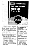
SPECIFICATION
Type of Engine ............................
Horsepower ........................
Maximum RPM .................
Weight ..................
Bore and Stroke
...........
Displacement
Air Cooled 2-Cycle
................
1.75
. ...................
(9 kg) .........
(36 mm x 30 ram)
.............
(30.5 cc)
Fuel Capacity-Engine Tank
....
(0.8 liters)
8000
19,8 Lbs. Approx,
....
1.42" x 1,18"
.............
1.86 cu.in.
..............
Ignition
4/5 qt,
Flywheel Magneto
Spark Plug ..............................
Spark Plug Gap Setting .......
Champinion
(0.6 mm)
RCJ-8
.025"
Bearings (Engine) ....................................
Bearings (Gear Hsg,) ..................
Starter ....
. ....................................
• PropellerDia.
andPitch
......
Ball
; ....
(171mmx104.4mm)
Bal! & Oilite Bronze
Recoil
.
6.73"x4.11"
Lub. (Gear Hsg.)
SAE 90
Fuel Mixture . . . 50 to 1 ratio of regular grade gasoline to 2-cycle outboard
lubricant or its equivalent BIA certified TC-W 2-cycle outboard lubricant.
Steering
243 ° Pivot Steering
...............
Owner's
iMPORTANT...........
Responsibility
BE SURE TO READ
OPERATING
SAFETY
CHECK
1.
Learn
2.
ities.
U.S. Coast Guard
and Operating
-- .........
Safety
Check
List
AND DO THE FOLLOWING
BEFORE
YOUR OUTBOARD
MOTOR
LIST
and observe
the
boating
laws
of the U.S,
Coast
Guard,
state,
iocat author_
;
regulations
require
the following:
a.
3.
4.
S,
Provide
an approved life-vest,
type 1,2 or 3, Personal Flotation
Device for each
person in boat.
(Encourage passengers to Wear them,)
b. If the boat exceeds 16 feet, also carry a type 4, throwable
Personal Flotation
Device,
Do not fill fuel tank with motor
running
or near any flame or lighted
smoking
material.
When loading boat distribute
the load evenly; keep the toad tow; don't
overload;
don't stand in a small boat.
Take weather and water conditions into account.
Do not permit
persons to ride on parts of the boat
Hot designed
Standing,
bow riding and seat back or gunwale riding can be especially
OWNER'S
6.
7,
8,
RESPONSIBILITY
Read owner's manual
before running your new outboard
motor,
Before starting, make sure your motor is securely mounted to boat transom
with a
safety chain, Tighten clamp stud handles securely by hand,
Be sure to have pliers, screwdriver,
spare spark ptugs, wrench, shear pins and cotter
pins in boat whenever leaving Shore.
9. : Be sure to have an adequate supply of fuel lcarry
I0.
for such use
dangerous.
only
in an approved
container}
on
board.
Use a good grade of regular gasoline with proper mixture,
as cited in the
Specifications.
Occasionally
check to be sure clamp stud handles on transom mounting
bracket are
tight.
IN CASE
11,
OF
SING THE
POSITION,
AN
STOP
EMERGENCY,
THE
BUTTON
PLACING
OR
• i'_: ¸ •••
OR AUXILIARY
failure
BY DEPRESFULL
CHOKE
Keep firefighting
and lifesaving
equipment
in good condition
and readily accessible
at all times,
Good housekeeping
is even more important
afloat than ashore.
Cleanliness diminishes the probability
of fire and tripping
hazards,
FOR TRAILERING
from
IN
Keep an alert lookout.
TIPS
have resulted
BE STOPPED
KNOB
13,
15.
accidents
CAN
CHOKE
=
12.
14,
Serious
ENGINE
to use eyes,
USE
When launching
or loading
boat on a trailer, place your outboard
motor
in the
tilted storage position,
Also when trailering
your boat and outboard
motor,
keep
outboard
motor
in upright
(vertical)
position
on the boat transom.
Outboard
motors transported
across rough roads in the "tilt"
position could cause transom
damage or mounting
brackets
to break off, toeing your motor.
If motor
must be
trailered
in "tilt"
position,
a short length of 2 x 4 should be placed between
the
motor bracket
and the motor
leg. The motor leg should then be firmly tied down
against
the 2 x 4 to prevent any possible damage,
Similar Precautions
should be
taken if using the motor
as an auxiliary
power source for a sailboat
or power boat.
When using motor
as an auxiliary
power source, the use of an auxiliary
adjustable
position
motor
bracket
is recommended.
•2
MAJOR
PARTS
Fuel Fi!ler Cap
and Air Ven[ Screw
ChokeLevi
Starlet Handle
Power Heed
Stop Bulton
Fuel Shul-oll Valve
Spark Plug
ThrottleControlLever
Reverse Driving Lock
Fuel SedimentBowl and Filler
" •
- Steerin_Handle
Idenlificalion
Plala
Till Pin Adjustment
ClampStudHandles:
TransomBracket
MufflerPipe
OriveShaftPipe
ExhaustOullel
CavitationPlale
Propeller
Culler Pi_
Fill and Drain Plug
Gear Housing
GearHousingCover
Figure l
Figure
:3
2
Figure 3
MAINTENANCE
1. FEATURE
INFORMATION
a. This
outboard
motor
has special design
features as shown in Figur:e 1,
b, Your seJection of our Marine Products will
provide_you
with
many
hours
Periodically
remove
muffler
cover
screwing
screws
and inspect
for
INSPECTION
build-up
inside the muffler
the
exhaust
port
and
by uncarbon
inlet and outlet,
the
combustion
boating.
To assure your, complete
satisfaction on the investment
you have just made,
we ask you to read this manual thoroughly
before going afloat,
Acquaint yourself with
chamber
of the cylinder,
Excessive carbon
will prevent drawing
the rhaximum
power_
outof
the engine. (See Figure 3),
b..Care
Should
be-exercised
white
cleaning
the particular
areas of operation
on your
outboard motor as you read the step-by-step
procedures.
Keep in mind maximum
performance
is achieved only when the owner
or operator
is completely
familiar with the
away carbon to prevent
scratches to the
surface of the engine components
and dropL
ping carbon inside of crankcase,
and assure prompt
2.
MUFFLER
a,
of enjoyable
operating instructions.
Periodic
servicing will be required,
It is
recommended
that you consult your Sears
Service Center when
service is necessary.
We will be happy to extend our facilities
:,
3,
LUBRICATION
service.
--_GEAR
4,
a,
.,
HOUSING
PROLONGED
(3)
(4)
out-
The
(4)
mounted
on a stand vertically
with
power head up for storage,
Pull starter handle slowly until resistance is felt due to compression
pressure, then stop, Release starter tension
possible corrosion to internal parts•
b. TO Check, Drain or Fill gear housing, follow:these steps:
(1)
Position outboard motor upright.
(6)
(3)
(4)
(5)
Replace plug and washer. Be sure plug
is tightened
securely,
To achieve complete
drainage of lubri-
outboard
motor
should
be
slowly to Prevent engine from
reversing
rotation
due
to
compression
pressure.
This position wilt :close both
the
intake
and
exhaust
ports
for
Recheck
after every fifty
(50)
hours
running time.
Replace with new lubricant at the end
of your outboard
motor season.
This
Remove
drain plug and washer, then
insert
nozzle of gear lubricant
tube:
into hole,
Squeeze tube until lubricant
is forced
out around tube.
for proas fol-
(3)
(5)
(2)
motor
outboard
See paragraph on stopping procedures.
When removing outboard
motor
from
boat, aliow all water
to drain from
unit,
is important,
as it removes any water
from
the gear housing .and prevents-
•
outboard
prepare
(1)
(2)
a, The Gear Housing has been pre-iubricated
at
the factory; however, the grease level should =be checked
as follows
using SAE 90
board motor grease. (See Figure 2).
(1)
Prior to initial operation.
(2)
After first four (4) hours of use.
STORAGE
TO store your
longed
Storage,
lows:
b.
storage,
Drain and fill gear housing as outlined
under Lubrication
of Gear Housing.
Wipe exterior
completely
with
fresh
water cloth and then apply light coating of oil.
When starting a new season, always use fresh
gasoline,
Last year's gasoline may
have
varnish deposits that wilt plug the carburetor jets, thus requiring
a complete
overhaul.
c.
To plan for the coming season, we recommend
you
contact
your
Sears
Service
Center before the new season for any service
repair work required.
cant, remove cotte[ pin, propeller
and
shea= pin from
propeller
shaft, also,
gear housing cover by unscrewing
2
bolts.
(6}
When lubricant
has completely
reptace
parts and refilJ gear
using filling procedure
above.
_. For
with
drained,
housing
best resutts, lubricate
propeller
shaft
lithium grease every 30 to 60 days.
4
OPERATION
_,
a.
BOAT
Mount
MOUNTING
the motor on the center
transom
{stern).
of the boat
(See Figure 4),
CAUTION
Hand
tighten
clamp
bracket
h0nd!_ _imuit0ne0u_ly,
clamp
stud
Do not use a
wrench or any other
device that would
cause damage to brackets,
Occasionally
check to be sure lamp stud handles on
transom
mounting
bracket
are tight,
L
.....
(See Figure 5).
b.
To obtain the best performance
from
your
outboard,
the following
boat transom specifications are recommended:
{See Figure 4),
Transom Angle (See View 3}:
Transom
.............
Height
(See view
View 3
20.7 °'
Figure
4
Figure
5
,
view 4
12 to 15 degrees
4):
............
_ . .20.7 inches
The angle of the motor
column
is easily
adjusted
by removing
the Hitch
Pin and
changing the Tilt Lock Bracket Pin in the
c,
three
(3) different
angle- position
holes
located
on either side of the right or left
Transom
Mounting
Brackets.
Each angle
position
elevates
five (5) degrees.
Try
center hole position first.
(See Figure 6).
To find the cot(act angle position, make a
test Pun at full
throttle
with your usual
loading
in the boat.
Always stop motor to
d.
change the Tilt Lock Bracket Pin, The correct angle
position
wil{ have your boat
traveling with the bow
the stern, but should
slightly
higher than
not porpoise
{bow
rises and falls rapidly
and continuously):
Be
sure Tilt Lock Bracket
Pin is always pushed
completely
through
both Transom
Mounting Brackets and Hitch Pin is secured.'
WARNING
If the motor column is tiited too far outward, the
boat is likely to porpoise or
cavitate
at full throttle,
which can be
dangerous because a cross wind or a wave
could suddenly
deflect
the boat into
a
dangerous
turn.
Als0,
if the
motor
column
is tilted too far inward, the bow
of the boat
will dig in, which can be
dangerous
when crossing a wake or in
rough water.
Do not run motor
in the
storage position.
(See View
t and 2,
Figure 4).
e.
,_ecura motor
Chain
S
.
to
not included
boat
with
with
motor.
Safety
Chain.
6; STEERING
ADJUSTMENT
Tighten
steering tension screw
driver for desired steering effort,
using a screw(See Figure 6).
J backed
There
is
outa too
possibility
CAUTION Of losing
far,
screw
if
1
PERATION
2-CYCLE
ENG4NE
FUEL
MIXTURE
;e a good grade of regular gasoline.
=table belowi)i
_- _ ,CAUTION
(See mix.
.
.
Always use BtA certified
TC-W oil in the
50:1 ratio,
Failure to dosomay
result in
excessive
spark
plug fouling,
pistOn
scoring, or bearing failure.
Do not under
any circumstances,
use multigrade,
such as
10W;30, or other automobile
oils.
If BtA certified
oil is not available, Use
an SAE 30 or 40 2-cycle or outboard oil.
we reser#a the right to refuse warranty on
parts
Which are
damaged
when. using
improper
fue!s Or lubricants.
:/ii_?
Gasoline
Figure 7
"
WARNING
is highly
_
flammable,
AlWays mix:
in we!l ventilated
area. - Do not fill tank
with,motor
_running,
nor near any flame
or,white
smoking.
Be sure, vent Screws
and fitter caps on tanks are finger tightened when
trunk
of
explosion.
transporting
gasoline in the
your automobi|e
to prevent
Figure 7A
[_
U.S. Measure
Regular_
IAmount of o_1
Gasoline
I
to be added
i,o
1
1
0.16
3
TAB LE
50:t
0,48
5
6
[
I
FUEL
:MIXING
I '°
2.6
7.7
I 0.80
I 0.96
I t2.8
{ t5.4
::
I
MIXTURE
I
I
Metric
Regular
Gasoline
in
"
.
8, STARTING
Measure!
i
Amount
of oil
tube added , ,,,,,
Liters
in Liters
0.02
'
0,10 _
0.20"
1
5
-10
20
_ Figure 8
e.
PROCEDURE
(See Fig. 7 &7A)
_. Open air vent screw located on fuel
cap by turning counterclockwise.
a. Open fuel shut-off valve.
:. Open throttle lever to half throttle.
J. Move choke lever to "On, position.
filler
are well
your balance
with
seated
handle
I
9.
slowly
until
you
feel
engage.
Then pull with
rapid
and allow
the starter cord to
slowly.
(See Figure 8),
After engine has started, graduafly move
choke
lever to "Off"
position
white
warming
up the engine.
Let
engine idle
for
approximately
3
minutes before
"Fast"
position.
so as not to lose I
a fast start.
retract
f.
g.
WARNING
1
When starting
outboard,
the boat will I
move with a sudden burst of speed. Make I
sure you
Pull starter
starter
motion
0.40
STOPPING
To stop engine,
"Stop"
position
(See Figure 7A)
moving
throttle
'
lever to
PROCEDURE
move
and
throttte
lever to full
press stop button.
6
OPERATION
WARNING
In case of an Emergency,
the engine can
be stopped by moving the Choke Lever to
Fult Choke Position..
if the motor
will not be operated for a
period of time, if it is to be removed from
the boat, or if it is to be tilted up, we
r_0rnm_nd
prevent
spillage
throat
and
formations
storage:
1.
Close
SLOW
the foll0wing practice to
from
the
carburetor;
bowl
and to prevent
gum.
in
the
carburetor
during
fuel
shut-off
valve
and
/--
Idle Adjusting
Figure 9
air
vent screw at fuel filler cap.
2.
Allow
motor
to run at idling
speed
until
it
stops of its own
accord,
• indicating
the
carburetor
has run
dry..
t0,
'
FLOODING
To clear engine of excess fuel, move choke lever
tO "Off"
position
and throttle
lever to half
throttle
position.,
Pull recoil starter
handle
until engine starts and continues
Figure 10
to run.
11,
CARBURETOR
ADJUSTMENTS
a. Your motor
has =a idle adjusting screw and
the idle speed has been preset at the facYory,
However,
you may need to adjust the idle
speed using [die Adjusting
Screw. Turn the
Screw clockwise
to increase motor
speed
and counter clockwise to decrease it. The
idle speed adjustment
must be done with
throttle
lever at full closed position and the_
idle speed should be as low as possible while
the engine runs steady.
(See Figure 9}
b.
Periodically
check filter for dirt
ing Sediment B0wl.
12.
PROPELLER
SHEAR
PIN
Figure 11
by unscrew-
&
CHAIN
HOLDER
a,
The Shear Pin is used for the purpose
of
protecting
the Drive Train and Gears. The
Shear Pin will not prevent
the proPefler
from becoming
damaged" when striking
an
under
water
object.
When shear pin is
broken,
the engine will continue
to run,
however, the propeller will not be rotating,
Figure 12
.Stop engine immediately
after shearing
pin to avoid possible
CAUTION
damage to the engine.
]
b.
To replace
shear pin,
shut. off
remove cotter
pin with pliers and
propeller.
(See Figures 10 & 11 ).
c.
Replace with new shear pin located in shear
pin and cotter pin holder. (See Figure 12),
7_
motor,
slip off
CONTACT-BREAKER
TIMING
LOCKING
AND
SCREWS
CONTACT
POINT_
. CONTACT*BREAKER
eASE PLATE
Figure 13
Screw
iPERATION
3•
FLYWHEEL
MAGNETO
SYSTEM
The magneto ignition
following component
Condenser,
13).
and
IGNITION
system consists of the
parts: Contact Points,
Ignition
Inspect the following
hard to start:
Coil.
if
plug as often
(See Figure
engine
fails
(1)
Spark
(2)
sure spark plug gap: setting
(0.Atom).
Gasoline
fuel supply
and
(3)
off valve should be open.
Carburetor being starved of fuel.
The correct spark
Champion
RCJ_8.
• To
test
ignition
plug
or
as necessary.
for
system,
is
Be
is .025"
fuel
this
Figure 14
shut,
'
!
motor
remove
is
spark
plug
part
and place against bare spot on metal =
of motor
away from: cylinder
spark
plug
hole and then
pull starter
cord several
times,
If a Spark bridges the plug gap, the
,magneto
is in good operating
condition,
The high tension
lead wire must be connected to the plug for this check•
If there
iS no spark, have the ignition
checked
at
your Sears Service Center.
WARNING
If the motor will not be operated
for a
period of time,
if it is to be remo_'ed
from the boat, or if it is to be tilted up,
we recommend
the following
practice to
preven t
spillage
from
the
carburetor
throat
and bowl
and to prevent
gum
formations
in
the _ carburetor
during
....
.
:
4.
REMOVING
MOTOR
FROM
BOAT
" "
. Always
tilt motor
by lifting
on rear of
shroud.
DO NOT PUSH DOWN
ON THE
STEERING
motor
from
HANDLE.
the boat,
Although
the
WARNING
engine is air cooled,
it
is
possible to burn your hands on the engine
block and upper portion
of the column.
Do not touch,
it
may
be necessary
to rotate
the motor
tO
one side before tilting
the motor
on the
transom to remove leg from the water when
installed on boats with thick transoms,
Always
carry
outboard
with
the engine
above the lower unit to prevent moisture
from
entering
the
engine
through
the
exhaust ports,
Steering handle serves as car_/ing handle as
shown in Figure 14A.
storage:
1.
Close fuel
When removing the
raise the outboard
in
upward
direction
until the propeller
clears
the transom.
Hold the motor upright long
enough ,to allow all water to drain from the
exhaust pipe.
When you find it difficult
to
hold the motor
upright, tighten the Center
8oil
increasingly
for desired effort.
(See
Figure 14).
[4A
Figure
2.
shut-off
valve and air vent
screw at fuel filler cap.
Allow motor
to run at
idling
speed
until it stops of its own accord,
indicating the carburetor
has run dry,
'
15,
To
SALT
WATER
materlally,increase
• parts and decorative
indicated below.
a,
b.
OPERATION
the
finishes,
Always
tilt
your motor
when not in use.
Never leave the lower
life
of all
exposed
fo]10w :the step s
out
unit
of
the water
in salt
water
oyernight,
c. Wipe exterior
completely
with fresh water
cloth and then apply light coating of oil,'
d, Lubricate
propeller
shaft occasionally
with
a waterproof
type of lubricant
(Lithium
Grease), thus enabling the propeller
to be
removed easily,
e.
f.
_t is go0c{ practice when operating
_n salt
water to inspect your
motor daily
and to
apply
a light
coating
of grease to any
part or area that shows evidence
of corrosion or rust,
Always
remove
motor
from
boat
vertically,
allowing
water to drain from column
before tilting the motor,
TROUBLE SHOOTING CHECK LIST
*Take
your
outboard
2000
X
x
x
x
x
Fuel Tank
Empty
Fuel
Shut-Off
Fuel
Line Kinked
x
X
X
x
X
X
Fuel
Filter
X
X
x
X
Vent
Screw
X
x
X
X
Carburetor
x
x
X
X
X
x
X
X
X
X
X
x
X
x
X
X
X
X
X
X
X
X
X
"X ....
X .....
Valve
Units,
Closed
or Pinched
Dirty
or Clogged
on Fuel Tank
Filter
Cap Closed
or Dirty
Fuai_-Oi'l'_'Mixtu re
Carburetor
Out
Engine
Flooded
X
Wrong
TyPe
X
' Defective
X
"Breaker
.........
of Adjostment,
-
:
Spark
or Fouled
Contact
Defective
×
into any one of over
' ...........
Passages Clogged
Incorrect
motor
Sears Service
Plug
..........:
..........
.
..........
Spark
Plug
_'
Points Ou,i o,!,Adjustment
,......
Magneto
q
X
Spark
Does
x
Engine
x
Breaker
0ut
Not Jump
Spark
Plug Gap
0f Time
......
X
..... X
"X
X
X
X
x
x
......
X
X
X
X
X
X
.... Weak
Contact
Ignition
Points Burned
€ol!
Weak or Defective
X,
X
Spark
X
X
Fraye d or (3ra'cked
" 'X
X
...............
........ i'i,
MODEL
SERIAL
DATE
NUMBER:
,,
Not Secured
Lead Wire
Insulation
....
Graunded or'Laose Wiring in Electrical System
' ProP'ei"ie,r,,8,o,un
d by Fareigr_"Obleczs .....
(Fishing Linel Weed,, El,::.),,
High Tension Lead-Salt Water Build Up
X
IMPORTANT
........
Condenser
Plug Lead Wire
Disconnected.
X
'
INFORMATION
IDENTIFICATION
*
....
PLATE
2981585070
NUMBER
OF
PURCHASE
INSURE
YOUR
ENGINE
Many
insurance
companies
including
Allstate
Insurance offer protection
contracts for your
boat and outboard
engine.
Insurance covering
your
own
equipment
against damage,
theft,
etc., as well as liability
insurance
for property
damage and personal
injury
to others is available.
tt would be wise to contact your, insurance
agent for further
information
about adequate
protection,
....
...... ,........
.O.PERATINGlOG
DATE
4
ar Pitted
NO, HRS, USED
GALS, FUEL USED
DATE
,. ,, ,;,:........
NO. HRS, USED
GALS, FUEL USED
==
REPLACEMENT_:PARTS :_
....
i
_ ....
FOR
-MODEL No. 298,585070
10
i
,0
!
I'N
150
80
81
L
7
6
5
4
44_
,I
a
FIG. 1
ENGINE
REF.
No,
PART
1" 1
0 t6-01046-200
1- 2
1-3
t-4
I-5
. 157-04000-900
018-00562-200
002-01046-800
0 t 7-01000-203
t-6
CYLINDER
SPARK
:::
046-01003-804
068-02000-200
1-13
1-14
t-15
070-02401-201.
099-61620-200
999-66t52-500
t,16
1-17
1-18
.076-01000-2t2
999_62101-004
071-02007-220
071-02007-230
071-02007-240
t-25
1.26
"
999-61620-200
_ ::999-66152-500.
1-27
1-28
_090-01000-200
076-0t000-212
:
_:
CRANK
CRANK
SHAFT
SHAFT
SHIM
SHIM
0.10
"0,15
CRANK
CRANK
SHAFT
SHAFT
SHIM
SHIM
0,20
030
BALL
BEARtNG
#6202
SECONDARY
CORD
MAGNETO
CAM
247-01000-201
CAM SUPPORT
POINT COVER
i
256-01046-200
900-t1050`t02
I
I
I
I
I
I
'"
I
i
:
. . CRANK CASE DRIVE SIDE
PRIMARY
CORD GROMMET
202-01003-20t
246-20701-201
1-55
!-65
1-66
I
I
OIL SEAL --15257
CRANK
CASE GASKET
1-34
1-52
I
I
I
I
I
I
112-01046-200
191-01046-200
999-67045-000_
'!73-20701:-802'
2
I
CRANK
CASE MAC SIDE COMP
NEEDLE BEARING
_1010
CONDENSER
COMP
1-33
1-46
1"51
I
I
2
I
1
1-31
1-32
t44
145
I
I
CRANK
SHAFT WASHER
BALL BEARING
;=6202
OIL SEAL 15257
203-01000,201
t67-20753-800
198-01046-900
155,20750-800
1-29
1-30
'.
' PRIMARY
CORD
CONTACT
BREAKER
ASS'Y
CRANK
SHAFT SHIM 0.05
!50-20701-900
071-02007-200
07t-02007-210
1-24
"
I
I
I
ASS'Y
PISTON PI N
'.....
. CRANK
SHAFT COMP
WOOD.RUFF
KEY 3 x 13 x 5
177-20701-80t
173-01046-800
1-19
1-20
SHROUD
PLUG
PISTON
031,01000.200
037,01000`200
:
Q'ty
. PISTON RING/TOP
PISTi3N RING/LOWER
CIR CLIP
04t-0i000-201
039-01000.200
t-ll
1-12
NAME
SPARK
PLUG RCJ-8
CYLINDER
COMP
CYLINDER
GASKET
040-O1000-201
:_
1-8
1-9
' ,1-10
PART
No.
IGNITION
CORD
.
COIL
COMP
SUPPORT
ASS'Y
MAGNETO
ROTOR
, FAN CASE
;
I
I
!
I
I
I
COMP
I
2
I
GROMMET
SPRING
I
I
O-RING G-45
PRIMARY
CORD
SPARK
'SCREW
PLUG RUBBER
5 x 10
I
I
COVER
B
•
I
4
4
1-67
1-68
1-69
902-10050-041
90041050-382
WASHER 5
SCREW 5 x
902-10050`042
990-t1040-061
1-70
1-74
994-15040-101
9g0-I1050-202
S. WASHER 5
SCREW 4 x 6
SCREW 4 x 10iP,S
1 q5
t-76
992-10050-042
065-00000-200
S. WASHER
FLYWHEEL
lq7
1-78
1-79
066,00000-200
990-11050-202
992-10050-042
FLYWHEEL
NUT
SCREW 5 x 20
S, WASHER 5
I
i
4
4
1_80
992-10060-042
S, WASHER
4
SCREW
38
5 x 20
5
WASHER
6
'
4
4
I
2
2
2
4
a
m
34
80
81
7
6
5
4
29
FiG.
1
REF.
ENGINE
No.
PART
1-81
1-91
1-92
1-93
1-94
1.95
1-96
1-150
No.
PART
991-01060-027
992-10040-012
NUT 6
S. WASHER
4
991`01030-011
992-10030-012
NUT 3
S. WASHER
3
992-01030-011
WASHER
Q'ty
4
t
1
1
1
3
3
SCREW,_X t0
990-11040-102
I
NAME
S. WASHER
992-i0040-042
985-35306-900
TOOL
3
1
4
KIT
r
r--
T
•
/-
•
•
L•
:i
i • •_
•,•
•
"'1'1
m
P
6]
62
Z
44 43
42
C
"1"1
"IR
!
I'1t
71
24
6566
48
49
=
F|G_2
:TANK
REF.
No.
&
PART
MUFFLER
No,
PART
2-1
2-2
756°00537-900
595-35100.902
2-3
300-35306;200
TANK CAP ASS'Y
ENGINE COVER
2-4
2-5
600-35! 00-203
401-35300-200
790-00601-202
TANK SUPPORT
TANK
STARTER
PAWL
992-01050-011
788-00601-203
WASHER 5
STARTER
PAWL
STARTER PAWL
'2-6
2-7
2-8
2.91
2-10
2-11
2-12
2-I3
2-14
2-t5
2-16
2-17
2-18 •
2-19
2-20
2-21
2-22
2-23
2-24
2-25
2-26
2-27
2-28
2-29
2-30
2-31
RECOIL
822-00601-200
793:10200-200
STARTER
STEP BOLT
COCK HOLDING
COCK ASS'Y
662-01046-200
"592-10201-900
594-00517_200
170.01046-800
.
3"t
NAME
ASS'Y
!
1
RING
1
1
1
SPRfNG
2
SHIM
2
2
2
METAL
2
1
1
1
COCK NUT
STOP BUTTON
I
266.00503-202/
181-01004-200
STOP BUTTON COVER
SPECIAL SPRING WASHER
1
1
! 60-01004-200
02t-35100-201
STOP BUTTON
PtN HOLDER
NUT
=
t
1
700.t450B-06B
700. t 4508.050
680-01004-200
701'-00517-200
FUEL PIPE
FUEL PIPE
CLIP ¢8
FUEL PiPE =STOPPER
LEAD VALVE SEAT GASKET
1
398-01000-202
395-01225-200
394-01202;201
399-01000-200
390.01046.200
455"22907"901
424"10201"200
r
LEAD
HOLDING
LEAD
LEAD
VALVE
VALVE
FIXING
1
3
1
METAL
1
t
2
1
COLLAR
LEAD VALVE SEAT
CARBURETOR
ASS'Y
CLEANER
CAP
1
t
437"10201 "200
333--01046.200
CLEANER
JOINT
CLUTCH HOLDING
737-01000.201
716-01046-200
MUFFLER
MUFFLER
GASKET
BODY A
245
737-01 046-200
717,.01 O46 -200
221-35600.200
2-46
226-35500-200
MUFFLER
MUFFLER
MUFFLER
MUFFLER
GASKET
BODY B
PiPE GASKET
PIPE STAY A
1
t
1
I
220-35300-200
225-35500-200
MUFFLER
MUFFLER
PIPE
PIPE STAY
t
1
2-49
227-35500-200
MUFFLER
PIPE STAY
2-50
2-51
990.11040-252
992-10040-042
2-52
2-_
990-11060-162
SCREW 4 x 25
S. WASHER 4
SCREW 6x
_6
2-41
2-42
243
247
2_
2-56
2-57
2-59
2-60
2-61
2_2
2-_
S. WASHER
992-10060,042
990-11030-10t
990-11040-162
992-10040-042
990-I 1040-302
992-10040-042
990-11040-122
992-10040-042
990-11060-202
992-1 O060-042
990.11050.122
_
1
1
BASE
1
1
B
1
3
3
3
3
6
SCREW 3 x 10
SCREW 4 x 16
S. WASHER 4
SCREW 4 x
S. WASHER
SCREW 4 x
S. WASHER
30
4
12
4
SCREW 6 x 20
S. WASHER 6 •
SCREW 5 x 12
2
6
6
2
':
2
5
5
2
2
2
]6,
"t'l
"-4
m
6i
62
73
"ri
rm
19
55
5857
FIG,2
TANK
REF.
& MUFFLER
PART
No.
2-64
2-65
2-66
No;
PART
992-10050-042
S. WASHER
SCREW 6 x
-S. WASHER
SCREW 6 x
S. WASHER
990-11060-252
992-10060-042
990-11060-! 22
992-10060-042
2-70
2-71
2-72
SHEAR
NAME
Q'ty
2
1
25
6
12
6
1
2
2
2
PIN
2-73
012-35500-200
011-35100-200
2-!00
2-101
330-35351-200
331-35351-200
SIDE
SIDE MARK: LEFT
1
1
2-102
2o103
906-35306-200
336-35! 18-200
NAME PLATE
STARTER
MARK
1
1
cOTTER
b
PIN
MARKRIGHT
,
r"
•
"
:
•:'
•
• ••
, =
|
•
,
/
z
•
,
S'3
_F.
RECOIL
No.
PART
STARTER
3- 0-1
3-1
756-00537-900
772-00537-200
3-2
774-04015,204
3-3
779-01006-201
776-01006_207
3-8
3-9
3-11
3-12
3-15
3-16
3*20
3-21
3-22
3-23
3-24
3-28
783-00517-200
780-00801-201
785-10207-901
773-00100-204
814-00500-200
990-11050_122
i
PART
No,
RECOIL
NAME
STARTER
* RECOIL STARTER
* STARTER
PULLEY
* RECOIL
SPRING
* PULLEY
* ROPE
SHAFT
*
"
"
"
ASS'Y
BODY
HANDLE
GUIDE
STARTER
HANDLE
ASS'Y
PULLEY SHAFT OUTER
STARTER
PULLEY
SHIM
992-10050-042
992-01060-041
*SCREW
5 x 12
* S.WASHER
5
* WASHER 6
992-10060-042
* S. WASHER
99141060-022
782-00546-200'
* BLIND NUT 6
* ROPE RECEIVE
6
Q'ty
1
1
I
1
1
1
1
t
1
1
2
2
1
1
1
1
FIG:4
I¢ARBURETOR
12
37
L
REF.
No.
4-0-1
4-1
4-2
4-3
4-4
4-5
PART
No.
455-22907-90'1
PART
'
560-22902-202
597-22602-200
B9_22900-200
CA R BU R ETO R -ASS'Y
* RUBBER CAP
* CABLE ADJUSTER
* BODYCAP
'
* THROTTLE
" THROTTLE
594-22602-200
619-22602-200
NAME
592-22907o9t0
591-22907-200
623-22900-200
62_22907-200
* ADJUSTER
SPRING
" ADJUSTER
SCREW
4-12
561-22900-900
607-22900-200
" BODY
4-16
4-17
4-2t
4-25
4-26
4-27
4-_
4-30
4-31
4-37
442
599-22907-200
606-22900,200
994:34040,121
605-22900_200
•
* JET NEEDLE ASS'Y
"="
THROTTLE
VALVE
BAND
ASS'Y
* CHAMBER
GASKET
* MAIN JET
* FLOAT CHAMBER
" SCREW 4 x 12/S
1
I
"
•
'_'-:
VALVE SPRING
SPRING SEAT
4-7
4-8
4-10
4-1t
i
Q*ty
:-
1
I
1
i
t
t
I
1
1
1
1
1
2
t
603-22900-800
628-22900-200
• FLOAT ARM PIN
* NEEDLE VALVE
• FLOAT ARM
604-22903-200
629-22900_200
• FLOAT
* DRAIN
994-31040061
570-22903-200
• SCREW 4 x 6
* GASKET
1
1
990-11940-061
* SCREW 4 x 6
1
GASKET
1
1
1
2O
;.5
HANDLE
& BRACKET
,ii
11
10
13
22
37
23
3O
31
29
28
34
FI G _!5:-HA
REF.
No.
NDLE:_:::
:& B-RA¢ KET _:;
PART
No.
PART
NAME
5-I
885-01046-800
THROTTLE
5-2
5-3
5-4
870-00005-930
990-I !050-252
991-01050-021
THROTTLE
LEVER
SCREW 5 x 25
5-5
5-6
!45-35500-202
990-21080-402
992-10080-042
5-7
5-8
5-9
5-10
5-11
5-12
5-I3
5-15
5-15
5-17
5-18
5-t9
5-20
5-21
5-22
5-23
5-24
5-25
5-26
5-27
5-28
5-29
5-30
5-31
5-32
5-33
5-34
5-35
S. WASHER
HANDLE,
HANDLE
162-35500-200
990-21080-302
992-01080-041
1
1
6
STEERING,
WASHER
I
2
1
ASS'Y
1
1
1
1
':
:'-
1
1
4
BRACKET
115-35500-204
131-35306-200
,"
:
"
THRUST BRACKET
RETURN
CAM
SCREW 6 x 10
GUIDE
S. WASHER
106_35119-800
5-38
5-39
108-35501-200
PLATE
1
4
4
BRACKET
PIN STOPPER A
BRACKET PIN S
CLAMP BRACKET
B COMP.
jl23-35500-201
107-35119-800
"
CLAMP BRACKET
BOLT 6 x 73
A COMP.
CLAMP BRACKET
CAP NUT 6
BUSHING
:
1
1
I
1
1
1
2
6
1
1
MARK
1
1
S, WASHER
WASHER 6
LEVER
t
1
1
t
1
5
SCREW 5 x 12
RETURN
SPRING
;
1
S. WASHER 5
SCREW 5 x 16
RETURN
CAM GUIDE
RETURN
: 138-35500-201
992:10050-042
990-11050-122
910_1046-200
4
1
S, WASHER 8
ADAPTER
COMP.
THRUST WASHER
992-10080-042
079-35350-800
t34-35500-201
5-36
5-37
54O
5-41
5-100
1
,,1
1
4
BOLT 8 x 30
WASHER 8
NUT 8
991-01080-021
991-41060_)22
992-10060-042
992-01060-041
1
8
STEP BOLT
WAVE WASHER
793-10200-200
992-04060-050
160-35500-900
990-21060-732
1
1
1
ASS'Y
SCREW 5 x 20
S. WASHER 5
HANDLE
STOPPER
161-35500-202
139-35500-200
129-35100-200
COMP
NUT 5
JOINT PIPE HOLDER
BOLT 8 x 40
"
990-1 t050-202
992-10050-042
t36-35500-200
990;11060-102
992-10050:042
990-1 t050-162
137-35500-201
WIRE
Q'W
22
:iG.6
DRIVE SHAFT PIPE &iGEARI!jCASE
i
1
2
15"I
17
25
27
26
18
1
3
2O
30
29
19
FIG.6
REF.
DRIVE
No.
6- 'I
6 2
6-3
6-4
6- .5
6-6
6-7
SHAFT
PART
090-35351
PIPE
&
No.
GEAR
PART
NAME
200
DRIVE
SHAFT
PiPE
075-35500 800
086-35500-200
999-62101-521
039-35500-200
091-35500-200
DRIVE
SHAFT
COMP
BEARING
NEEDLE
BEARING
HOLDER
BEARING
HOLDER
DRIVE SHAFT
BOLT 8 _ 40
S. WASHER 8
CASE
1
1
CL1P
1015
6-8
6.9
6-10
6-11
6-12
034-35500-200
091-35500-200
615
03t-35500
6-15-t
6 15-2
999-61600-000
032-35500-210
GEAR CASE ASS'Y
• BALL BEARING
_----6000
* PLANT BEARING
L
6-15-3
6.17
999-66102 200
171-35500-201
"OIL
SEAL
PROPELLER
t0228
SHAFT
SHiM
A 0.10
173-35500-200
174-35500-200
175-35500-200
PROPELLER
PROPELLER
SHAFT
SHAFT
SHIM
SHiM
A 0.20
A 0.30
PROPELLER
STOP RING
GEAR
SHAFT
SHIM
A t,0
6-18
6-19
6-20
900
013-35500-200
0t 7-36t20-200
330_0200-210
6-22
6-23
6-24
6-25
6-26
6-27
6-28
!
t
1
1
1
1
1
}
1
l
01
GEAR
SHAFT
SHIM
0.2
1
t
048-35500-202
999-61600-100
GEAR SHAFT SHIM 0.3
GEAR CASE GASKET
BALL BEARING
_t6001
1
1
1
046-35500.260
999-66t22-266
GEAR CASE COVER
OIL SEAL 12227
1
019-35500-201
012-35500-200
PROPELLER
SHEAR PIN
011-35100-200
010 35306-200
COTTER PIN
PROPELLER
SCREW 6 x 18
6-32
063-35500-200
064-35500-200
6-39
1
2
SHIM
99£-11060-182
992-11060-042
999-62102-463
6-36
6-37
6-38
GASKET
SHAFT
6-29
6-30
6-31
6-33
6-34
6-35
PIPE
GEAR
330-00200-230
330-00200-240
6-21
1
1
)
1
BOLT 8 x 40
S. WASHER 8
GEAR CASE HOLDER
SHAFT
3
2
2
1
PIPE GASKET
990-21080-402
992-10080-042
990-21080-402
992-10080-042
DRIVE
Q'ty
066-35500.200
062-35500-200
060-35300-200
COMP
1
1
SHAFT
3
3
1
2
S. WASHER 6
THRUST BEARING
DRIVE
SHAFT
DRIVE
DRIVE
PtNION
SHAFT SHIM
SHAFT SHIM
COLLAR
SHIM
061-35600-200
026-35500-200
PINION
PINION PiN 4 x 16
GEAR COLLAR
025-35500-200
317-02000-200
GEAR PIN
GROMMET
GASKET
990-11060-082
SCREW 6 x 8
0.50
2
1
1
0 10
0.20
t
1
1024
1
1
1
1
1
1
l
SERVICE MEMO
j
J•,
MODEL NO.
298.585070.
;?
For quick service or repair, take your Outboard
Motor to any Sears Service Unit throughout
the
U.S. and Canada,
Each Service Unit is staffed
by trained
technicians,
using Sears approved
parts and repair procedures
to ensure that we
meet our pledge to you-"We
service what we
sell." Refer to the focal telephone directory
for
the Sears Unit nearest you.
HOW TO ORDER REPAIR PARTS
Refer to the Identification
Plate for the complete model number when reques,ting service or
replacement
parts for your outboard motor.
All parts listed herein may be ordered
any Sears, Roebuck and Co.
WHEN
WAYS
TION:
ORDERING
REPAIR
GIVE THE FOLLOWING
1. Model Number
2, Part Number
from
PARTS,
ALINFORMA-
3. Part Name
4. Quantity
IN
_APAN
For one year from Ihe t=rstday el use 0f
this Outboard motor, when all instruCtions and procedures detailed m the
0wner"s Manual are fo_t0wed, Sears
wifI repair detects m mater_al or
workmanship which appear m fhe outboard motor, free of charge
If the outboard meter is _sed for cornmercia{ or renta_ purposes, thiS warranty apPIies lot only thirly days hem
me firs_day 0f use
Warranty Service is available by simply
returning the outboard motor to the
nearest Searsslore m the United Slates
OrCanada. Warranty _svahd m counlry
of purchase
This warranty gives you specific legal
nghls, and you may also have other
rights which vary from state Io sta_e.
SEARS,ROEBUCKAND CO,
If the parts you need are not stocked locally,
your order will be electronically
transmitted
to a Sears; Repair Parts Distribution
Center for
expedited
handling,
PRINTI_I3
FULL ONEYEARWARRANTYON
OUTBOARDMOTOR
SIEARR.
SLITSf owet"
BSC41,3
Chi_:_ga,]L 60684
SIMPSONS-SEARSLIMITED
222 Jlrvls
RI31FRIJ_K
S!
/tNr_ t"tt_
1oronlo.
OnLiilo,
Clrlidz
P.hie..',_,_t,.Ii
_til_l