1
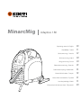
MinarcMig
Adaptive 180
Operating manual • English
Käyttöohje • Suomi
EN
FI
Bruksanvisning • Svenska
SV
Bruksanvisning • Norsk
NO
Brugsanvisning • Dansk
DA
Gebrauchsanweisung • Deutsch
DE
Gebruiksaanwijzing • Nederlands
NL
Manuel d’utilisation • Français
FR
Manual de instrucciones • Español
ES
Instrukcja obsługi • Polski
PL
Инструкции по эксплуатации • По-русски
RU
EN
Operating manual
English
MinarcMig 180 / © Kemppi Oy / 1117
MinarcMig 180 / © Kemppi Oy / 1117
Contents
1.PREFACE.................................................................................................................. 3
1.1General........................................................................................................................... 3
1.2Properties .................................................................................................................... 3
1.3 About welding .......................................................................................................... 4
2.
2.1
2.2
2.3
2.4
2.5
EN
2.6
2.7
MACHINE USE .................................................................................................. 5
Before implementation ....................................................................................... 5
General view of the machine............................................................................ 6
Distribution network.............................................................................................. 6
Cable connections .................................................................................................. 6
Filler wire ...................................................................................................................... 9
2.5.1 Changing the feed roll groove .................................................................. 9
2.5.2 Threading the filler wire ........................................................................... 10
2.5.3 Reversing polarity ....................................................................................... 11
Controls and indicator lights.......................................................................... 12
2.6.1 Display in automatic mode ..................................................................... 13
2.6.2 Welding power adjustment in automatic mode ............................. 14
2.6.3 Arc length trimmer in automatic mode ............................................. 14
2.6.4 Display in manual mode .......................................................................... 15
2.6.5 Adjustments in manual mode ............................................................... 15
Threading the shoulder strap........................................................................ 16
3.SERVICE ............................................................................................................... 17
3.1 Daily maintenance .............................................................................................. 17
3.2 Maintenance of the wire feed mechanism ............................................ 17
3.3Disposal...................................................................................................................... 19
4.TROUBLESHOOTING............................................................................. 19
5. Ordering numbers.......................................................................... 20
6.Technical data...................................................................................... 21
2
PREFACE
1.1
General
Congratulations on choosing the MinarcMig equipment. Used correctly,
Kemppi products can significantly increase the productivity of your welding,
and provide years of economical service.
This operating manual contains important information on the use,
maintenance and safety of your Kemppi product. The technical specifications
of the equipment can be found at the end of the manual.
Please read the manual carefully before using the equipment for the first
time. For your own safety and that of your working environment, pay
particular attention to the safety instructions in the manual.
For more information on Kemppi products, contact Kemppi Oy, consult an
authorised Kemppi dealer, or visit the Kemppi web site at www.kemppi.com.
The specifications presented in this manual are subject to change without
prior notice.
Important notes
Items in the manual that require particular attention in order to minimise
damage and personal harm are indicated with the ’NOTE!’ notation. Read
these sections carefully and follow their instructions.
1.2
Properties
MinarcMig Adaptive 180 is an easy-to-use MIG welding machine suitable
for both hobby and professional use. The welding machine is small, efficient
and extremely light. It is easy to carry with the help of a shoulder strap. The
machine is suitable for a range of different purposes and the possibility to
use a long extention cord eases operation in various sites. It is also suitable
for generator use on construction sites.
The machine has both an automatic and manul mode. In the automatic
mode, you must first select the filler wire material after which the welding
voltage and wire feed speed can be adjusted with one control according
to the thickness of the welded sheet. Thus, selecting the right parameters is
easy. In automatic mode, the length of the arc, or welding heat, is trimmed
with another control. In manual mode, the welding voltage and wire feed
speed are adjusted separately with their own controls. The use of the
machine is aided with a display which also displays the welding current,
welding voltage and wire feed speed.
3
MinarcMig 180 / © Kemppi Oy / 1117
1.
EN
MinarcMig 180 / © Kemppi Oy / 1117
You can also use steel wire (solid or cored wire), stainless steel wire or
aluminium wire as filler wire in the machine. The steel wire can be 0.6 mm, 0.8
mm or 1.0 mm thick, but the machine’s welding properties are optimum with
a steel wire of 0.8 mm diameter. The stainless steel wire can be 0.8 mm, 0.9
mm or 1.0 mm in diameter and the aluminium wire 1.0 mm.
1.3
About welding
In addition to the welding machine, welding outcome is influenced
by the piece being welded and the welding environment. Therefore,
recommendations in this manual must be followed.
During welding electric current is led with the welding gun’s current nozzle
to the filler wire and via that to the welded piece. Earthing cable attached to
the workpiece guides the current back to the machine, forming the needed
closed circuit. Unrestricted current flow is possible when the earthing clamp
is properly attached to the workpiece and the fixing point of the clamp on
the workpiece is clean, paintless and rustfree.
Shielding gas must be used during welding in order to prevent air from
mixing with the weld pool. Pure carbon dioxide or a mixture of argon and
carbon dioxide is suitable for steel wire shielding gas. Argon + 2 % CO²
mixture is suitable for stainless steel wires. Argon is suitable for welding
aluminium wires. Some filler wires form a shielding gas from the wire’s filling
as it melts thus eliminating the need for a separate shielding gas.
EN
4
MACHINE USE
The machine is delivered ready for operation without adjustments with
0.8 mm diameter filler wire.
If you use different thickness filler wire, make sure that the feed roll groove,
welding gun contact tip and machine polarity are suited for the used
wire size and type. If you mainly use aluminium or stainless steel wire, we
recommend you change the wire guide to a plastic one which is better suited
for the wire type.
2.1
Before implementation
The products are packed to durable packages especially designed for them.
However, always make sure before use that the products have not been
damaged during transportation. Check also, that you have received the
products you ordered and the instruction manuals needed. Product packing
material is recyclable.
Transportation
The machine should be transported in an upright position.
NOTE! Always move the welding machine by lifting it from the handle. Never pull
it from the welding gun or other cables.
Environment
The machine is suitable for both indoor and outdoor use, but it should be
protected from heavy rain and sunshine. Store the machine in a dry and clean
environment and protect it from sand and dust during use and storage. The
recommended operating temperature range is -20° C – +40° C.
Place the machine in such a way that it does not come in contact with hot
surfaces, sparks and spatters.
Make sure the air flow in the machine is unrestricted.
5
MinarcMig 180 / © Kemppi Oy / 1117
2.
EN
MinarcMig 180 / © Kemppi Oy / 1117
2.2
General view of the machine
1.
2.
3.
4.
5.
EN
2.3
Welding gun
Earthing cable
Main switch
Supply voltage cable
Shielding gas hose connector
Distribution network
All regular electrical devices without special circuits generate harmonic
currents into distribution network. High rates of harmonic current may cause
losses and disturbance to some equipment.
WARNING: This equipment does not comply with IEC 61000-3-12. If it is
connected to a public low voltage system, it is the responsibility of the
installer or user of the equipment to ensure, by consultation with the
distribution network operator if necessary, that the equipment may be
connected.
2.4
Cable connections
Connection to the mains
The machine is equipped with a 3.3 m long supply voltage cable and plug.
Connect the supply voltage cable to the mains.
NOTE! The fuse size needed is 16 A delayed.
If you use an extension cord, its cross-sectional area should be at least as
large as the supply voltage cable’s (3 x 2.5 mm²). The maximum length for the
extension cord is 50 m.
6
Earthing
The earthing cable is already connected to the machine. Clean the workpiece
surface and fix the earthing cable clamp to the piece in order to create a
closed and interference-free circuit needed for welding.
Welding gun
The welding gun is already connected to the machine. The welding gun
leads the filler wire, shielding gas and electric current to the weld. When you
press the welding gun trigger, shielding gas flow and wire feed begin. The arc
ignites, when the filler wire touches the welded piece.
The factory-installed wire guide in the welding gun is best suited for steel
wire welding. However, it can temporarily be used for stainless steel wire
and aluminium wire welding. Then, however, friction is greater and thus the
wire feed may tangle. If you mainly use stainless steel or aluminium wire, we
recommend you change the wire guide to a plastic wire guide.
The gun neck can be rotated 360°. When turning the neck, always make
sure that the neck is twisted almost all the way to the bottom. This prevents
damaging and overheating the neck.
NOTE! If you use other than 0.8 mm diameter filler wire, change the welding gun
contact tip to match the wire thickness.
7
MinarcMig 180 / © Kemppi Oy / 1117
The machine can also be used with a generator. The minimum power for the
generator is 4.2 kVA, and the recommended power 8.0 kVA in order for the
machine to be used at maximum capacity.
EN
MinarcMig 180 / © Kemppi Oy / 1117
Shielding gas
The shielding gas used for steel wires is carbon dioxide or a mixture of argon
and carbon dioxide which replaces air in the arc’s area. Shielding gas for
stainless steel wires is a mixture of argon and carbon dioxide (2%) and argon
for aluminium wires. Thickness of the welded sheet and welding power
define the flow rate of the shielding gas.
The machine is delivered with a 4.5 m long shielding gas hose. Connect the
bayonet socket of the shielding gas hose to the machine’s hose connector
and the hose connector end to the gas bottle’s control valve.
EN
1. Connect the hose to the gas bottle’s control valve and tighten the
connector.
2. Adjust the flow rate with the control valve screw. A suitable shielding gas
flow rate is 8–15 l/min.
3. Close the bottle’s valve after use.
NOTE! Use a shielding gas suitable for the material’s welding. Fix the gas bottle
securely in an upright position before installing the control valve.
8
Filler wire
The machine is delivered with the welding gun connected to +pole making it
suitable for steel solid wire, stainless steel wire and aluminium wire welding
without adjustments.
2.5.1 Changing the feed roll groove
The feed roll groove is factory set for welding filler wires of 0.8–1.0 mm
diameter. The feed roll groove must be changed if you use 0.6 mm thick filler
wire.
MinarcMig 180 / © Kemppi Oy / 1117
2.5
EN
1. Open the feed roll from the pressure control lever.
2. Switch the machine on from the main switch.
3. Press the welding gun trigger and drive the feed roll in such a position
that its locking screw is up and can be opened.
4. Switch the power off from the main switch.
5. Open the feed roll locking screw with a 2.0 mm Allen wrench
approximately half a turn.
6. Pull the feed roll from its shaft.
7. Turn the feed roll and reinstall it to its shaft all the way to the bottom
making sure that the screw is on the shaft’s level.
8. Tighten the feed roll locking screw.
9
MinarcMig 180 / © Kemppi Oy / 1117
2.5.2 Threading the filler wire
EN
1. Open the reel housing by pressing on the opening button and install
the wire reel in such a way that it rotates counter clockwise. You can
use either a 5 kg (diameter 200 mm) or 1 kg (100 mm) wire reel in the
machine.
2. Attach the reel with a reel lock.
3. Unfasten the wire end from the reel, but hold on to it all the time.
4. Straighten the wire end for approximately 20 cm and cut the wire in the
straightened location.
5. Open the pressure control lever which then opens the feed gear.
6. Thread the wire through the wire’s rear guide to the gun’s wire guide.
7. Close the feed gear and fasten it with the pressure control lever. Make
sure that the wire runs in the feed roll groove.
8. Adjust the compression pressure with the pressure control lever no
higher than to the middle of the scale. If the pressure is too high, it
removes metal fragments from the wire surface and may damage the
wire. On the other hand, if the pressure is too low, the feed gear slips and
the wire does not run smoothly.
9. Press the welding gun trigger and wait for the wire to come out.
10. Close the reel housing cover.
10
2.5.3 Reversing polarity
Some filler wires are recommended to be welded with the gun in the –pole,
so the polarity should be reversed. Check the recommended polarity from
the filler wire package.
MinarcMig 180 / © Kemppi Oy / 1117
NOTE! When driving the wire in to the gun, do not point the gun at yourself or
others or put, for example, your hand in front of the tip, because the cut wire end
is extremely sharp. Also, do not put your fingers near the feed rolls, because they
might get squeezed between the rolls.
EN
1. Disconnect the machine from the mains.
2. Bend the rubber cover of the earthing cable’s pole in such way that the
cable can be disconnected.
3. Remove poles’ tightening nuts and washers. Note the correct order of
the washers!
4. Interchange the cables.
5. Install the washers in place and close the tightening nuts to spanner
tightness.
6. Put the rubber cover of the earthing cable’s pole firmly in place. The
rubber cover must always protect the earthing cable’s pole.
11
MinarcMig 180 / © Kemppi Oy / 1117
2.6
Controls and indicator lights
3.
4.
5.
7.
1.
6.
2.
EN
1. Welding power control (automatic mode) OR Wire feed speed control
(manual mode)
2. Arc length trimmer (automatic mode) OR Welding voltage control
(manual mode)
3. Standby indicator light
4. Overheating indicator light
5. Mode selection button
6. Material selection button (automatic mode)
7. Display
In automatic mode, the welding power is adjusted according to the thickness
of the welded sheet. The machine also has a trimmer for arc length in
automatic mode. There are three material options for filler wires and you can
browse through them with the material selection button.
In manual mode, the wire feed speed and welding voltage are adjusted
separately. Modes can be changed with the mode selection button. Note that
material or sheet thickness selections made in the automatic mode are not
valid in manual mode or manual mode’s selections in automatic mode.
Indicator lights display the machine’s standby mode and inform of a possible
overheating.
12
2.6.1 Display in automatic mode
EN
MinarcMig 180 / © Kemppi Oy / 1117
When you switch the machine on, a green standby light switches on.
Simultaneously, the main switch indicator light switches on. If the machine
overheats or the supply voltage is too low or too high, the welding operation
automatically switches off and the yellow overheating indicator light
switches on. The light switches off when the machine is ready for operation
again. Make sure that there is enough space around the machine allowing air
to freely flow and cool the machine.
1. Sheet thickness
2. Chart for sheet thickness and arc length trimmer
3. Operating mode
4. Material
5. Shielding gas and wire diameter recommendation
6. Wire feed speed chart
7. Welding values: wire feed speed, welding voltage and welding current
Sheet thickness displays the selected welding power setting which is based
on the fillet weld’s sheet thickness in millimetres. When you adjust the
welding power according to sheet thickness, the sheet thickness in the chart
changes thinner or thicker correspondingly.
The selected operating mode and material are shown on the display. The
display also shows a recommendation as to what shielding gas and wire
diameter should be used with the material in question.
During welding, the wire feed speed chart displays the wire’s speed.
Of all the welding parameters, only filler wire feed speed is visible on the
display all the time. Welding voltage and welding current are visible on the
13
MinarcMig 180 / © Kemppi Oy / 1117
display during welding. The last used values remain on the display until
welding is restarted or settings are changed.
When adjusting the arc length, the voltage display shows a comparative scale
(-9…0…9) which will disappear from the display after some time once the
adjustment is made.
2.6.2 Welding power adjustment in automatic mode
Adjusting the welding power according to sheet thickness affects
simultaneously both wire feed speed and amount of current lead to the wire.
This is a good starting point for welding in different operating situations.
However, connection type and root opening may influence the amount of
welding power needed.
Select the correct parameter with the welding power control according
to the welded fillet weld’s sheet thickness. If the fillet weld’s sheets are of
different thickness, use their average as a default parameter.
Sheet thickness display has been given in millimetres and it is based on ,
with steel and stainless steel wires, 0.8 mm wire diameter. When using a 0.6
mm wire, set the welding power control slightly higher than the used sheet
thickness and correspondingly slightly lower with 0.9–1.0 mm wires. With
aluminium wires, the welding power adjustment is based on 1.0 mm wire
diameter.
EN
NOTE! When welding for the first time, we recommend that you set the arc
length trimmer to 0.
2.6.3 Arc length trimmer in automatic mode
The arc length trimmer adjusts the length of the arc shorter or longer and
affects the welding temperature. A shorter arc is colder and a longer one
hotter. The arc length trimmer also affects the arc’s welding properties and
spatters with different combinations of filler wire diameters and shielding
gases. The trimmer range is -9...0...9: negative values shorten and positive
values lenghten the arc. The trimmer is preset at 0 which is, in most cases, a
suitable basic setting.
If the weld is too convex, the arc is too short or cold. Then adjust the arc
longer or hotter by turning the control clockwise.
If, on the other hand, you want to weld with a colder arc to prevent for
example the parent material from burning through, adjust the arc shorter by
turning the control counter clockwise. You can also adjust the welding power,
if need be.
When adjusting the arc length, the weld on the arc trimmer chart on the
display correspondingly changes more concave or convex.
14
MinarcMig 180 / © Kemppi Oy / 1117
Once the arc has been trimmed, it usually does not need to be changed
when the welded sheet thickness changes.
2.6.4 Display in manual mode
1. Operating mode
2. Wire feed speed chart
3. Welding values: wire feed speed, welding voltage and welding current
The selected operating mode is visible on the display. During welding, the
wire feed speed chart displays the wire’s speed.
Wire feed speed is the only welding parameter always visible on the display.
When adjusting welding voltage, the display shows the set value for the
voltage, and only during welding does the display show the actual value.
Welding current is visible on the display only during welding.
Values for actual welding voltage and welding current remain on the display
after welding until welding is restarted or settings are changed.
2.6.5 Adjustments in manual mode
In manual mode, the wire feed speed and welding voltage are both adjusted
separately. Welding current and power are defined according to wire feed
speed. The desired arc and welding properties can be reached by adjusting
the voltage.
15
EN
MinarcMig 180 / © Kemppi Oy / 1117
2.7
Threading the shoulder strap
EN
The machine is delivered with a shoulder strap which helps carrying the
machine. Thread the shoulder strap in place according to the picture.
NOTE! The machine should not be hung up from the shoulder strap.
16
SERVICE
When servicing the machine, its utilization degree and environmental
circumstances should be taken into account. If you use the machine
appropriately and service it regularly, you will spare yourself from
unnecessary malfunctions.
NOTE! Disconnect the machine from the mains before handling the electrical
cables.
3.1
Daily maintenance
• Remove welding spatters from the welding gun’s tip and check the
condition of the parts. Change damaged parts to new ones immediately.
Only use original Kemppi spare parts.
• Check that the insulating tips of the welding gun’s neck are undamaged
and in place. Change damaged insulation parts to new ones
immediately.
• Check the tightness of the welding gun’s and earthing cable’s
connections.
• Check the condition of the supply voltage and welding cable and
replace faulty cables.
3.2
Maintenance of the wire feed mechanism
Service the wire feed mechanism at least every time the reel is changed.
• Check the wear of the feed roll groove and change the feed roll when
necessary.
• Clean the welding gun wire guide with compressed air.
17
MinarcMig 180 / © Kemppi Oy / 1117
3.
EN
MinarcMig 180 / © Kemppi Oy / 1117
Cleaning the wire guide
Pressure of the feed rolls remove metal dust from the filler wire’s surface
which then finds its way to the wire guide. If the wire guide is not cleaned, it
gradually clogs up and causes wire feed malfunctions. Clean the wire guide
in the following manner:
1. Remove the welding gun’s gas nozzle, contact tip and contact tip’s
adapter.
2. With a pneumatic pistol, blow compressed air through the wire guide.
3. Blow the wire feed mechanism and reel housing clean with compressed
air.
4. Reattach the welding gun’s parts. Tighten the contact tip and contact
tip’s adapter to spanner tightness.
Changing the wire guide
If the wire guide is too worn or totally clogged, change it to a new one
according to the following instructions. The wire guide should also be
replaced with a plastic one, if you mainly use stailess steel or aluminium wire.
1. Disconnect the welding gun from the machine.
A. Disconnect the cable clamp of the gun’s power cable by opening the
screws.
B. Disconnect the gun’s power cable from the machine’s pole.
C. Disconnect the connector of the trigger conductors from the
machine.
D. Open the gun’s mounting nut.
E. Extract the gun gently from the machine whereupon all parts come
through the front part’s cable hole.
2. Open the mounting nut of the wire guide which exposes the end of the
wire guide.
3. Straighten the welding gun’s cable and withdraw the wire guide from
the gun.
4. Push a new wire guide in to the gun. Make sure that the wire guide
enters all the way into the contact tip’s adapter and that there is an
o-ring at the machine-end of the guide.
5. Tighten the wire guide in place with the mounting nut.
6. Cut the wire guide 2 mm from the mounting nut and file the sharp
edges of the cut round.
7. Reattach the gun in place and tighten the parts to spanner tightness.
EN
18
Disposal
Do not dispose of electrical equipment with normal waste!
In observance of European Directive 2002/96/EC on waste electrical
and electronic equipment, and its implementation in accordance with
national law, electrical equipment that has reached the end of its life must
be collected separately and taken to an appropriate environmentally
responsible recycling facility.
The owner of the equipment is obliged to deliver a decommissioned unit
to a regional collection centre, per the instructions of local authorities
or a Kemppi representative. By applying this European Directive you will
improve the environment and human health.
4.
TROUBLESHOOTING
Problem
Cause
The wire does not
move or wire feed
entangles
Feed rolls, wire conduit or contact tips are defective
• Check that feed rolls are not too tight or too loose
• Check that the feed roll groove is not too worn
• Check that the wire conduit is not blocked
• Check that the contact tip and wire guide are suitable for the wire used
• Check that there are no spatters on the conduit tip and that the hole is not
cramped or worn loosei
Main switch indicator
does not switch on
The machine has no supply voltage light • Check supply voltage fuses
• Check supply voltage cable and plug
Machine welds badly
Welding outcome is influenced by several factors
• Check that the wire feed is constant
• Check the trimming settings of welding power control and arc length
• Check the material selection setting
• Check that the earthing clamp is fixed properly, fixing point is clean, and both
cable and its connections are undamaged
• Check that the shielding gas is suitable for the wire material used
• Check the flow of shielding gas from the tip of the welding gun
• Supply voltage is uneven, too low or too high
Over-heating
indicator light
switches on
The machine has over-heated • Check that cooling air can flow without obstructions
• Machine’s volume-capacity ratio has been exceeded; wait for the indicator light to
switch off
• The supply voltage is too low or too high
MinarcMig 180 / © Kemppi Oy / 1117
3.3
EN
19
MinarcMig 180 / © Kemppi Oy / 1117
5.
Ordering numbers
Product
Ordering number
MinarcMig™ Adaptive 180
(includung gun, cables, gas hose and shoulder strap)
6108180
Welding gun MMG20 (3 m)
6250200
Earthing cable and clamp (3 m)
6184003
Shielding gas hose (4.5 m)
W001077
Shoulder strap
9592162
Consumables for wire feed mechanism
EN
Feed roll 0.6–1.0 mm
W000749
Feed roll 0.8–1.0 mm, knurled
W001692
Pressure roll
9510112
Wire rear guide
W000651
Parts for wire reel hub
Reel flange
W000728
Spring
W000980
Wire reel lock
W000727
Consumables for MMG20 gun
20
Gas nozzle
9580101
Gas nozzle insulating bush
9591010
Contact tip M6 ø 0.6 mm
9876634
Contact tip M6 ø 0.8 mm
9876635
Contact tip M6 ø 0.9 mm
9876633
Contact tip M6 ø 1.0 mm
9876636
Contact tip adapter
9580173
Neck insulating ring
9591079
Wire guide 0.6–1.0 mm (Fe)
4307650
Wire guide 0.6–1.0 mm (Ss, Al)
4307660
Technical data
MinarcMig 180 / © Kemppi Oy / 1117
6.
MinarcMig™ Adaptive 180
Connection voltage
1 ~ 230 V ±15%, 50/60 Hz
Rated power
• 25% ED
8.6 kVA 180 A
• 60% ED
5.3 kVA 120A
• 100% ED
4.2 kVA 100A
Supply current
I1max
32 A
I1eff
16 A
Connection cable
3G2.5(3.3 m)
Fuse (delayed)
16 A
EN
Load capacity 40° C
• 25% ED
180 A / 23.0 V
• 60% ED
120 A / 20.0 V
• 100% ED
100 A / 19.0 V
Welding range
20 A/12 V – 180 A/23 V
Wire feed speed adjustment range
1–12 m/min
Open circuit voltage
15.5– 42.5 V
Power factor
0.60 (180 A / 23,0 V)
Efficiency
81% (180 A / 23,0 V)
Filler wires:
• Fe solid wire
ø 0.6...1.0 mm
• Fe cored wire
ø 0.8...1.0 mm
• Ss
ø 0.8...1.0 mm
• Al
ø 1.0 mm
Shielding gases
CO², Ar, Ar+CO² -mixed
200 mm / 5 kg
Wire spool (max. ø)
21
MinarcMig 180 / © Kemppi Oy / 1117
EN
22
Temperature class
H (180° C) / F (155° C)
External dimensions LxWxH
400 x 180 x 340 mm
Weight (incl. gun and cables 3,0 kg)
9.8 kg
Operating temperature range
-20° C...+40° C
Storage temperature range
-40° C...+60° C
Degree of protection
IP23S
EMC class
A
EN
23
MinarcMig 180 / © Kemppi Oy / 1117
KEMPPI OY
Hennalankatu 39
PL 13
FIN-15801 LAHTI
FINLAND
Tel +358 3 899 11
Telefax +358 3 899 428
[email protected]
www.kemppi.com
Kotimaan myynti:
Tel +358 3 899 11
Telefax +358 3 734 8398
[email protected]
KEMPPI SVERIGE AB
Box 717
S-194 27 UPPLANDS VÄSBY
SVERIGE
Tel +46 8 590 783 00
Telefax +46 8 590 823 94
[email protected]
KEMPPI NORGE A/S
Postboks 2151, Postterminalen
N-3103 TØNSBERG
NORGE
Tel +47 33 346000
Telefax +47 33 346010
[email protected]
KEMPPI DANMARK A/S
Literbuen 11
DK-2740 SKOVLUNDE
DANMARK
Tel +45 4494 1677
Telefax +45 4494 1536
[email protected]
KEMPPI BENELUX B.V.
Postbus 5603
NL-4801 EA BREDA
NEDERLAND
Tel +31 765717750
Telefax +31 765716345
[email protected]
KEMPPI FRANCE S.A.S.
65 Avenue de la Couronne des Prés
78681 EPONE CEDEX
FRANCE
Tel +33 1 30 90 04 40
Telefax +33 1 30 90 04 45
[email protected]
KEMPPI GmbH
Otto-Hahn-Straße 14
D-35510 BUTZBACH
DEUTSCHLAND
Tel +49 6033 88 020
Telefax +49 6033 72 528
[email protected]
KEMPPI SPÓŁKA Z O.O.
Ul. Borzymowska 32
03-565 WARSZAWA
POLAND
Tel +48 22 7816162
Telefax +48 22 7816505
[email protected]
KEMPPI AUSTRALIA PTY LTD.
13 Cullen Place
P.O. Box 5256, Greystanes NSW 2145
SMITHFIELD NSW 2164
AUSTRALIA
Tel. +61 2 9605 9500
Telefax +61 2 9605 5999
[email protected]
OOO KEMPPI
Polkovaya str. 1, Building 6
127018 MOSCOW
RUSSIA
Tel +7 495 739 4304
Telefax +7 495 739 4305
[email protected]
ООО КЕМППИ
ул. Полковая 1, строение 6
127018 Москва
Tel +7 495 739 4304
Telefax +7 495 739 4305
[email protected]
KEMPPI, TRADING (BEIJING) COMPANY,
LIMITED
Room 420, 3 Zone, Building B,
No.12 Hongda North Street,
Beijing Economic Development Zone,
100176 Beijing
CHINA
Tel +86-10-6787 6064
+86-10-6787 1282
Telefax +86-10-6787 5259
[email protected]
肯倍贸易(北京)有限公司
中国北京经济技术开发区宏达
北路12号
创新大厦B座三区420室
(100176)
电话: +86-10-6787 6064
+86-10-6787 1282
传真: +86-10-6787 5259
[email protected]
KEMPPI INDIA PVT LTD
LAKSHMI TOWERS
New No. 2/770,
First Main Road,
KAZURA Gardens,
Neelangarai,
CHENNAI - 600 041
TAMIL NADU
Tel +91-44-4567 1200
Telefax +91-44-4567 1234
[email protected]
191017210
1117
www.kemppi.com
KEMPPI (UK) Ltd
Martti Kemppi Building
Fraser Road
Priory Business Park
BEDFORD, MK44 3WH
UNITED KINGDOM
Tel +44 (0)845 6444201
Telefax +44 (0)845 6444202
[email protected]