1
JH-Turbo-Engels1a
30-06-2002
13:17
Pagina 1
MARINE DIESEL ENGINE
MODELS:
4JH3-TE/-HTE/-DTE/-TCE Series
OPERATION MANUAL
GB
California
Proposition 65 Warning
Diesel engine exhaust and some of
its constituents are recognized by
the State of California to cause
cancer, birth defects, and other
reproductive harm.
Warranty-GB.fm Page 1 Tuesday, February 22, 2005 9:06 PM
Warranty
YANMAR CO., LTD. LIMITED EMISSIONS CONTROL SYSTEM WARRANTY
Your Warranty Rights and Obligations:
California:
The California Air Resources Board and Yanmar Co., Ltd. ("Yanmar") is pleased to explain the
emission control system warranty on your off-road compression-ignition model year 2000 or
later engine. In California, new heavy-duty off-road engines must be designed, built and
equipped to meet the State's stringent anti-smog standards.
All States
Yanmar warrants that the engine is: (1) designed, built and equipped so as to conform with all
applicable emissions regulations, including in California, all applicable regulations adopted by
the Air Resources Board; and (2) free from defects in materials and workmanship which cause
such engine to fail to conform with applicable emissions regulations for its warranty period.
Yanmar warrants the emission control system on your engine for the periods of time listed below provided there has been no abuse, neglect or improper maintenance of your engine. Your
emission control system may include parts such as the fuel injection system and the air induction system. Also included may be hoses, belts, connectors and other emission-related assemblies.
GB
Where a warrantable condition exists, Yanmar will repair your heavy-duty off-road engine at
no expense to you for diagnosis, parts or labor. Warranty services or repairs wiII be provided
at a Yanmar authorized Dealer.
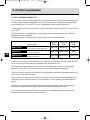
Manufacturer's Warranty Period:
The model year 2000 or later heavy-duty off-road engines are warranted for the periods listed
below. If any emission-related part on your engine is defective, the part will be replaced by
Yanmar.
Engine Type
Warranty Period by Number of Years or Hours of 0peration
Engines rated at or above 19 kW
Warranty period is five (5) years or 3,000 hours of use, whichever
occurs first. In the absence of a device to measure hours of use, the
engine has a warranty period of five (5) years.
Engines rated under 19 kW
Warranty period is two (2) years or 1,500 hours of use, whichever
occurs first. In the absence of a device to measure hours of use, the
engine has a warranty period of two (2) years.
Warranty period is two (2) years or 1,500 hours of use, whichever
Constant speed engines rated
occurs first. In the absence of a device to measure hours of use, the
under 37 kW with rated speeds
greater than or equal to 3,000 min-1 engine has a warranty period of five (5) years,
Constant speed engines rated at or
above 37 kW
Warranty period is five (5) years or 3,000 hours of use, whichever
occurs first. In the absence of a device to measure hours of use, the
engine has a warranty period of five (5) years.
Warranty-GB.fm Page 2 Tuesday, February 22, 2005 9:06 PM
Warranty Coverage:
This warranty is transferable to each subsequent purchaser for the duration of the warranty
period. Repair or replacement of any warranted part will be performed at an authorized Yanmar dealer.
Warranted parts not scheduled for replacement as required maintenance in the owner's manual shall be warranted for the warranty period. Any part repaired or replaced under warranty
shall be warranted for the remaining warranty period. Warranted parts scheduled for replacement as required maintenance in the owner's manual are warranted for the period of time prior
to the first scheduled replacement.
Yanmar is liable for damages to other engine components caused by the failure of any warranted part during the warranty period.
Any replacement part which is functionally identical to the original equipment part in all respects may be used in the maintenance or repair of your engine, and shall not reduce Yanmar's warranty obligations. Add-on or modified parts that are not exempted may not be used.
The use of any non-exempted add-on or modified parts shall be grounds for disallowing a warranty.
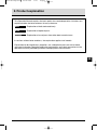
Warranted Systems/ Parts Covered by this Warranty:
(1)
(2)
(3)
(4)
(5)
Fuel Injection System
Cold start enrichment system
Intake manifold
Turbocharger Systems
Exhaust manifold
Exclusions:
Failures other than those arising from defects in material or workmanship are not covered by
this warranty. The Warranty does not extend to the following: malfunctions caused by abuse,
misuse, improper adjustment, modification, alteration, tampering, disconnection, improper or
inadequate maintenance, or use of non-recommended fuels or lubricating oils; accidentcaused damage, or replacement of expendable items made in connection with scheduled
maintenance. Yanmar disclaims any responsibility for incidental or consequential damages
such as loss of time, inconvenience, loss of use of equipment/engine or commercial loss.
Owner's Warranty Responsibilities:
As the heavy-duty off-road engine owner, you are responsible for the performance of
the required maintenance listed in your owner's manual.
Yanmar recommends that you retain all documentation, including receipts, covering maintenance on your heavy-duty off-road engine, but Yanmar cannot deny warranty solely for the
lack of receipts, or for your failure to ensure the performance of all scheduled maintenance.
Your engine is designed to operate on diesel fuel only. Use of any other fuel may result in your
engine no longer operating in compliance with applicable emissions requirements.
You are responsible for initiating the warranty process. You must present your off-road engine
to a Yanmar Dealer as soon as a problem exists. The warranty repairs should be completed
by the Dealer as expeditiously as possible. If you have any questions regarding your warranty
rights and responsibilities, or would like information on the nearest Yanmar Dealer/authorized
service center, you should contact Yanmar Marine U.S.A. Corp. at Adairsville, GA U.S.A.
GB
JH-Turbo-Engels1a
30-06-2002
13:17
Pagina 2
Contents
CONTENTS
3.3 Operating your Engine ...................... 25
3.3.1 Inspection Before Starting ...... 25
3.3.2 How to Start the Engine .......... 27
3.3.3 Operation................................ 28
3.3.4 Cautions during Operation...... 29
3.3.5 Stopping the Engine ............... 30
3.3.6 Procedure............................... 31
3.4 Long term Storage ............................ 32
INTRODUCTION .............................................. 3
1
FOR YOUR SAFETY ................................... 4
1.1 Warning symbols ................................ 4
1.2 Safety Precautions.............................. 4
1.3 Warning Labels ................................... 7
2
PRODUCT EXPLANATION ......................... 8
2.1 Use, Driving System etc...................... 8
2.2 Engine Specifications ....................... 10
2.3 Names of Parts ..................................13
2.4 Major Servicing Parts.........................14
2.5 Control Equipment ............................15
2.5.1 Control Panel...........................15
2.5.2 Remote Control Handle...........18
2.5.3 Stopping Equipment ...............19
GB
3
2
OPERATION ............................................. 20
3.1 Fuel Oil, Lube Oil & Cooling Water .... 20
3.1.1 Fuel Oil.................................... 20
3.1.2 Lube Oil .................................. 20
3.1.3 Cooling Water......................... 21
3.2 Before Initial Operation ..................... 22
3.2.1 Supply Fuel Oil........................ 22
3.2.2 Bleeding the fuel system......... 22
3.2.3 Supply Engine Lube Oil........... 22
3.2.4 Supply Clutch Lube Oil .......... 23
3.2.5 Supply Cooling Water............. 23
3.2.6 Cranking (Idling)...................... 24
3.2.7 Check and Resupply Lube
Oil and Cooling Water ............. 25
4
MAINTENANCE & INSPECTION ............... 34
4.1 General Inspection Rules .................. 34
4.2 List of Periodic Inspection Items ....... 35
4.3 Periodic Inspection Items ................. 37
4.3.1 Inspection on Initial 50 Hrs. of
Operation (or after 1 month) .... 37
4.3.2 Inspection Every 50 Hours
(or monthly)............................. 38
4.3.3 Inspection Every 250 Hrs ........ 39
4.3.4 Inspection Every 500 Hrs ........ 42
4.3.5 Inspection Every 1000 Hrs ...... 42
5
TROUBLE AND TROUBLESHOOTING..... 43
5.1 Trouble and Troubleshooting............ 43
5.2 Emergency Repairs for Clutch .......... 44
6
PIPING DIAGRAMS .................................. 47
7
WIRING DIAGRAMS ................................. 48
APPENDIX A (Piping diagrams)..................... A-1
(See the back of this Manual)
APPENDIX B (Wiring diagrams) .................... B-1
(See the back of this Manual)
JH-Turbo-Engels1a
30-06-2002
13:17
Pagina 3
Introduction
Thank you for purchasing a YANMAR Marine Diesel Engine.
This Operation Manual describes the operation, maintenance and inspection of the
4JH3-TE/-HTE/-DTE/-TCE Series Yanmar Marine Diesel Engines.
Read this Operation Manual carefully before operating the engine to ensure that it is used
correctly and that it stays in the best possible condition.
Keep this Operation Manual in a convenient place for easy access.
If this Operation Manual is lost or damaged, order a new one from your dealer or distributor.
Make sure this manual is transfered to subsequent owners. It should be considered as a
permanent part of the engine and remain so.
GB
Constant efforts are made to improve the quality and performance of Yanmar products, so
some details included in this Operation Manual may differ slightly from your engine. If you
have any questions about this, please contact your Yanmar dealer or distributor.
Models
Operation Manual
(Marine Engine)
Code. No.
4JH3-TE/-HTE/-DTE/-TCE
49961-202850
3
JH-Turbo-Engels1a
30-06-2002
13:17
Pagina 4
1. For your safety
1.1 WARNING SYMBOLS
Most operation, maintenance and inspection problems arise due to users’ failure to comply
with the rules and precautions for safe operation described in this operation manual. Often,
users do not understand or recognize the signs of approaching problems. Improper
handling can cause burns and other injuries and can result in death.
Be sure to read this operation manual carefully before operating the engine and observe all
of the instructions and precautions described in this manual.
Below follow the warning signs used in this manual and on the products. Pay special
attention to parts containing these words and signs.
GB
DANGER
DANGER indicates an imminently hazardous
situation which, if not avoided, WILL result in death
or serious injury.
WARNING
WARNING indicates a potentially hazardous situation which, if not avoided, COULD result in death or
serious injury.
CAUTION
CAUTION indicates a potentially hazardous situation
which, if not avoided, MAY result in minor or
moderate injury.
This sign is also be used to alert against unsafe
practices.
The descriptions captioned by NOTICE are particularly important cautions for
handling. If you ignore them, the performance of your machine may deteriorate leading to
problems.
1.2 SAFETY PRECAUTIONS
(Observe these instructions for your own safety!)
Precautions for Operation
DANGER
4
Filler Cap of Fresh Water Tank
Never open the cap of the fresh water tank while the engine is still hot.
Steam and hot water will spurt out and burn you seriously. Wait until the
temperature of the fresh water tank has dropped, wrap a cloth around
the filler cap and loosen the cap slowly. After inspection, refasten the
cap firmly.
JH-Turbo-Engels1a
30-06-2002
13:17
Pagina 5
1. For your safety
DANGER
Battery
Never smoke or permit sparks near the battery, because it may emit
explosive hydrogen gas. Place the battery in a well-ventilated place.
DANGER
Fuel
Use only diesel oil. Never use other fuels, including gasoline, kerosene,
etc., because they could cause a fire. The wrong fuel could also cause
the fuel injection pump and injector to fail due to lack of proper
lubrication. Be sure to check that you have selected the correct diesel
fuel before filling the fuel tank.
DANGER
Fire Prevention
Be sure to stop the engine and confirm that there are no open flames in
the vicinity before supplying fuel. If you do spill fuel, wipe such spillage
carefully and dispose of the wiping materials properly. Wash your hands
thorougly with soap and water.
Never place oil or other flammable material in the engine room.
Install a fire extinguisher near the engine room, and familiarize yourself
with its use.
WARNING
Exhaust Gas
Exhaust gas contains poisonous carbon monoxide and should not be
inhaled.
Be sure to install ventilation ports or ventilators in the engine room and
ensure good ventilation during engine operation.
WARNING
Moving Parts
Do not touch or let your clothing get caught in the moving parts of the
engine, such as the front drive shaft, V-belt or propeller shaft, during
engine operation. You will be injured.
Never operate the engine without the covers on the moving parts.
Before starting the engine, check to see that any tools or cloths used in
maintenance have been removed from the area.
CAUTION
Burns
The whole engine is hot during operation and immediately after
stopping. The turbocharger, intercooler, exhaust manifold, exhaust pipe
and high pressure fuel pipe are very hot. Never touch these parts with
your body or clothing.
5
GB
JH-Turbo-Engels1a
30-06-2002
13:17
Pagina 6
1. For your safety
WARNING
Alcohol
Never operate the engine while you are under the influence of alcohol.
Never operate the engine when you are ill or feeling unwell.
SAFETY PRECAUTIONS FOR INSPECTION
DANGER
Battery Fluid
Battery fluid is dilute sulfuric acid. It can blind you if it gets in your eyes,
or burn your skin. Keep the fluid away from your body. If you touch it,
wash it off immediately with a large quantity or fresh water and call your
doctor for treatment.
WARNING
Fire by Electric Short-Circuits
Always turn off the battery switch before inspecting the electrical
system.
Failure to do so could cause short-circuiting and fires.
WARNING
Stop the engine before servicing
Stop the engine before you service it.
Turn the battery switch off. If you must inspect while the engine is in
operation, never touch moving parts. Keep your body and clothing well
clear of all moving parts.
GB
CAUTION
6
Scalds
If extracting oil from the engine while it is still hot, don’t let the oil splash
on you.
Wait until the temperature has dropped before extracting cooling water
from the engine. Don’t let it splash on you.
NOTICE
Forbidden Modifications
Never release the limiting devices such as the engine speed limit, fuel
injection limit, etc.
Modification will impair the safety and performance of the product and
shorten product life.
Also note that any troubles arising from modification are not covered by
our warranty.
NOTICE
Precautions for Treating Waste
Never dispose of waste oil or other fluid in a field, sewer, river, or the sea.
Treat waste matters safely observing regulations or laws.
Ask a waste recovery company to collect it.
JH-Turbo-Engels1a
30-06-2002
13:17
Pagina 7
1. For your safety
SAFETY PRECAUTIONS FOR INSPECTION
1.3 WARNING LABELS
To insure safe operation, warning device
labels have been attached. Their location is
shown below and they should always be
visible. Please replace if damaged or lost.
Product Safety Labels, Parts Code Numbers
128377-07350
128296-07260
128296-07300
196630-12980
GB
7
JH-Turbo-Engels1a
30-06-2002
13:17
Pagina 8
2. Product explanation
2.1 USE, DRIVING SYSTEM, ETC.
This is a light, compact diesel engine for use in pleasure boats. The engine is equipped with
a turbocharger and intercooler which insures maximum output while preserving lightness
and compact size. (The 4JH3-TE series is equipped with the turbocharger only.)
Power output for this group of engines increases progressively from 4JH3-TE, 4JH3-HTE to
4JH3-DTE.
The inboard series is equipped with a marine gear connecting the output shaft with the
propeller shaft for operation.
The different types of marine gears used for each series are shown below.
GB
Marine Gear
4JH3-TE
Series
4JH3-HTE
Series
4JH3-DTE
Series
KBW21 Clutch
Mechanical wet cone clutch
Input/output special parallel drive
4JH3-TE
4JH3-HTE
N/A
KM4A Clutch
Mechanical wet cone clutch
7° Down angle drive
4JH3-TBE 4JH3-HTBE
KMH4A Clutch
Hydraulic wet multiple disk clutch
8° Down angle drive
4JH3-THE 4JH3-HTHE 4JH3-DTHE
N/A
In order to obtain full performance from your engine, it is imperative that you check the size
and structure of the hull and use a propeller of the appropriate size.
The engine must be installed correctly with safe cooling water and exhaust piping and
electrical wiring. The PTO work should be easy to use for onboard equipment.
The laws of some countries may require hull and engine inspections, depending on the use,
size and cruising area of the boat.
The installation, fitting and surveying of this engine all require specialized knowledge and
engineering skills. Consult Yanmar’s local subsidiary in your region or your distributor or
dealer.
Consult your Yanmar dealer or distributor when selecting optional parts. Optional parts
selections should take into account operational and surrounding conditions.
This Operation Manual explains the basic points for standard operation. Variations are
explained under the specially marked sections.
8
JH-Turbo-Engels1a
30-06-2002
13:17
Pagina 9
2. Product explanation
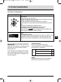
This Operation Manual explains the basic points for standard operation. Variations are
explained under the letter emblems for easy reference.
Model
: Explanation of indicated model only.
Option
: Explanation of optional parts.
Customer
: Explanation of use of parts from other boat manufacturers.
In sections without letter emblems, the explanation applies to all models.
Explanation for driving devices, propellers, etc. and optional parts are not included,
and special attention should be paid to the explanations and safety precautions in the
operation manuals provided by the boat and equipment manufacturers.
GB
9
JH-Turbo-Engels1a
30-06-2002
13:17
Pagina 10
2. Product explanation
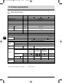
2.2 Engine Specifications
2.2.1
Item
Unit
Engine Model
--
Type
--
Model
4JH3-TE
4JH3-TBE
4JH3-THE
4JH3-TCE
vertical 4-cycle water cooled diesel engine
direct injection
Combustion system
--
Number of cylinders
--
Bore x stroke
mm
Displacement
1.995
Aspiration system
--
turbocharger
Continuous
rating output
Output/crankshaft
speed
kW/rpm
(hp/rpm)
50.7 / 3700
(69 / 3700)
One hour
rating output
Output/crankshaft
speed
kW/rpm
(hp/rpm)
55.2 / 3800
(75 / 3800)
Low idling
rpm
Fuel injection timing (b.T.D.C.)
º
Fuel injection pressure
kg/cm
4
84 x 90
700 ± 25
12 ± 1
2
220 ± 5
at flywheel side
Main power take off
at crankshaft V-pulley side
Front power take off
GB
Direction of
rotation
clockwise
Propeller shaft (ahead)
bi-rotation
fresh water cooler with heat exchanger
Cooling system
complete enclosed forced lubrication
Lubrication system
electric
Type
Starting
system
Starting motor
DC 12V, 1.4 kW
AC generator
12V, 55A (12V, 80A optional)
Engine
Lubricating oil
capacity (rake angle)
standard
unit Model
Type
Reduction ratio
Lubricating oil
capacity
LxWxH
7.05
(0°)
Total
KM4A
KMH4A
hydraulic wet
mechanical wet
multiple disk clutch
cone clutch 7°
down angle drive 8° down angle drive
SD40-4TSail Drive
Cone clutch
Forward
2.17
2.62
1.47 2.14 2.63 3.30
2.04
2.45
2.32
Reverse
3.06
3.06
1.47 2.14 2.63 3.30
2.04
2.45
2.32
mm
1.2
1.3
2.0
906 x 560 x 635
888 x 565 x 635
938 x 565 x 635
1086 x 565 x 433
250
260
Cooling water Fresh water tank
capacity
Subtank
Engine weight with marine gear
kg
1.) Rating condition: ISO 3046-1 and ISO 8665
10
6.3
(7°)
KWB21
mechanical wet
multiple disk clutch
Input/output eccentric parallel drive
Marine gear
Dimensions
counter-clockwise or
clockwise viewed from
stem
Counter-clockwise viewed from stern
Crankshaft
1.8
6.0
0.8
249
2.) 1hp=0.7355 kW
247
JH-Turbo-Engels1a
30-06-2002
13:17
Pagina 11
2. Product explanation
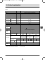
2.2.2
Item
Unit
Engine Model
--
Type
Model
--
4JH3-HTE
4JH3-HTBE
4JH3-HTHE
vertical 4-cycle water cooled diesel engine
Combustion system
--
direct injection
Number of cylinders
--
Bore x stroke
mm
4
84 x 90
Displacement
1.995
Aspiration system
--
turbocharger, intercooler
Continuous
rating output
Output/crankshaft
speed
kW/rpm
(hp/rpm)
67.7 / 3700
(92 / 3700)
One hour
rating output
Output/crankshaft
speed
kW/rpm
(hp/rpm)
73.6 / 3800
(100 / 3800)
Low idling
rpm
Fuel injection timing (b.T.D.C.)
º
Fuel injection pressure
kg/cm
700 ± 25
12 ± 1
2
220 ± 5
at flywheel side
Main power take off
at crankshaft V-pulley side
Front power take off
Direction of
rotation
Counter-clockwise viewed from stern
Crankshaft
clockwise
Propeller shaft (ahead)
fresh water cooler with heat exchanger
Cooling system
complete enclosed forced lubrication
Lubrication system
electric
Type
Starting
system
Starting motor
Engine
Lubricating oil
capacity (rake angle)
DC 12V, 1.4 kW
12V, 55A (12V, 80A optional)
AC generator
standard
unit Model
Reduction ratio
LxWxH
7.5
(0°)
KWB21
Type
Lubricating oil
capacity
6.3
(7°)
KM4A
mechanical wet multiple mechanical wet cone
disk clutch Input/output clutch 7° down angle
eccentric parallel drive
drive
Marine gear
Dimensions
GB
bi-rotation
Total
KMH4A
hydraulic wet multiple
disk clutch 8° down
angle drive
Forward
2.17
2.62
1.47 2.14 2.63 3.30
2.04
2.45
Reverse
3.06
3.06
1.47 2.14 2.63 3.30
2.04
2.45
mm
1.2
906 x 576 x 660
Cooling water Fresh water tank
capacity
Subtank
Engine weight with marine gear
kg
1.) Rating condition: ISO 3046-1 and ISO 8665
1.3
2.0
888 x 581 x 660
938 x 581 x 660
7.2
0.8
258
256
259
2.) 1hp=0.7355 kW
11
JH-Turbo-Engels1a
30-06-2002
13:17
Pagina 12
2. Product explanation
2.2.3
Item
Unit
Engine Model
--
Type
Model
--
4JH3-DTHE
vertical 4-cycle water cooled diesel engine
Combustion system
--
direct injection
Number of cylinders
--
Bore x stroke
mm
4
84 x 90
Displacement
1.995
Aspiration system
--
turbocharger, intercooler
Continuous
rating output
Output/crankshaft
speed
kW/rpm
(hp/rpm)
85.3 / 3700
(116.0 / 3700)
One hour
rating output
Output/crankshaft
speed
kW/rpm
(hp/rpm)
91.9 / 3800
(125 / 3800)
Low idling
rpm
Fuel injection timing (b.T.D.C.)
º
Fuel injection pressure
kg/cm
700 ± 25
12 ± 1
2
220 ± 5
at flywheel side
Main power take off
at crankshaft V-pulley side
Front power take off
GB
Direction of
rotation
clockwise viewed from stern
Crankshaft
bi-rotation
Propeller shaft (ahead)
fresh water cooler with heat exchanger
Cooling system
complete enclosed forced lubrication
Lubrication system
electric
Type
Starting
system
Starting motor
Engine
Lubricating oil
capacity (rake angle)
DC 12V, 1.4 kW
12V, 55A (12V, 80A optional)
AC generator
standard
unit Model
KMH4A
hydraulic wet multiple disk clutch 8° down angle drive
Type
Marine gear
Reduction ratio
Lubricating oil
capacity
Dimensions
7.5
(0°)
Total
LxWxH
Forward
2.04
2.45
Reverse
2.04
2.45
2.0
mm
938 x 581 x 660
Cooling water Fresh water tank
capacity
Subtank
0.8
Engine weight with marine gear
kg
260
1.) Rating condition: ISO 3046-1 and ISO 8665
12
7.2
2.) 1hp=0.7355 kW
JH-Turbo-Engels1a
30-06-2002
13:17
Pagina 13
2. Product explanation
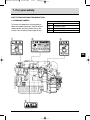
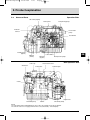
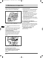
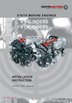
2.3
Names of Parts
Operation Side
Oil cooler (engine)
Name plate
Fuel priming pump
Intake air
silencer
Fresh water
pump
Fuel oil filter
Trawling lever
(option)
GB
Lube oil filter
Dipstick
(clutch)
Dipstick
(engine)
Non Operation Side
Filler cap
Alternator
Fuel injection pump
Fresh water cooler
* Intercooler
Turbocharger
V-belt
Seawater pump
Starter
Clutch lever
Oil cooler(clutch)
NOTE:
The 4JH3-DTHE engine (with KMH4A clutch) is used as the example for the above diagram.
The 4JH3-TE Series is not equipped with an intercooler (indicated by * in the diagram).
13
JH-Turbo-Engels1a
30-06-2002
13:17
Pagina 14
2. Product explanation
2.4
GB
Major Servicing Parts
Name of part
Function
Fuel filter
Removes dust and water from fuel. The internal element (filter) should be
changed periodically.
A water separator is on the bottom of the filter and should be drained
periodically.
Fuel priming pump
This is a manual fuel pump. Moving the knob on the top of the fuel filter
feeds the fuel. The pump is also used to bleed air from the fuel system.
Fuel feed pump
This is a mechanical pump used to feed fuel to the fuel injection pump. It is
built into the fuel injection pump.
Filler port (engine)
Filler port for engine lube oil.
Filler port (marine gear)
Filler port for marine gear lube oil.
Dipstick (Lube oil)
Gauge stick for determinining the level of the engine and marine gear oil.
Lube oil filter
Filters fine metal fragments and carbon from the lube oil.
Filtered lube oil is distributed to the engine’s moving parts.
Cooling System
Seawater passes through the heat exchanger cooling the fresh water,
which in turn cools the engine.
Fresh water cooling
Fresh water pump
There are two cooling systems: fresh water and seawater.
The fresh water pump is run by the alternator and the V-belt.
Fresh water cooling
The fresh water in the fresh water cooler is fed to the engine by the fresh
water pump. The cooling fresh water returns to the engine after it is cooled
with seawater in the fresh water cooler.
Filler cap
The filler cap on the cooling water tank covers the water supply port. The
cap has a pressure regulating valve. When the cooling water temp. rises,
the pressure rises inside the fresh water cooler.
Subtank
The pressure regulating valve releases vapor and hot water overflow to the
subtank.
Oil cooler (engine oil)
This heat exchanger cools high temp. engine oil with seawater.
Oil cooler (clutch oil)
This heat exchanger cools high temp. clutch oil with seawater.
Turbocharger
With the pressurized intake air feeding device the exhaust gas turbine is
rotated by exhaust gas, and the power is used to rotate the blower.
This pressurizes the intake air for sending to the cylinder gives high power
output.
Intercooler
This heat exchanger cools the pressurized intake air from the
turbocharger with seawater and further compresses it.
Intake air silencer
This is the air intake silencer. The silencer guards against dirt in the air and
reduces the noise of air intake.
Name plate
Name plates are provided on the engine and the marine gear and have the
model, serial number and other data.
Starter
Starter motor for the engine. Powered by the battery.
Alternator
Rotates by belt drive, generates electricity and charges the battery.
14
JH-Turbo-Engels1a
30-06-2002
13:18
Pagina 15
2. Product explanation
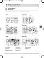
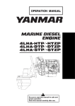
2.5 Control Equipment
2.5.1 Control Panel
The instrument panel is located in the control room. The following instruments enable you to
start/stop the engine and to monitor its condition during operation.
B type
New B type
C type
New C type
GB
D type
New D type
Tachometre
Hour metre
C.W. temp. metre
L.O. temp. metre
Boost pressure metre
Alarm lamps
Starter switch
Stop button switch
Buzzer stop switch
Alarm buzzer
Illumination switch
Digital clock
Fuse
15
JH-Turbo-Engels1a
30-06-2002
13:18
Pagina 16
2. Product explanation
(1) Metres
The following metres are located in the
upper centre part of the instrument panel.
• B/C/D and New B/C/D type panels use
analog electric systems and have a
pointer indicator.
GB
Turn the panel light switch ON for easy
viewing.
• Tachometre
The engine's rotation speed is indicated.
Load and engine rotation can be
monitored.
• Hour metre
The number of hours of operation is
indicated, and can be used as a guide for
periodic maintenance checks.
• Cooling Water Temperature Metre
Option Instrument Panel C.D.
The cooling water temperature is
indicated. Enables monitoring of the
cooling condition of the engine.
• Lube Oil Pressure Metre
Option Instrument Panel C.D.
The engine oil pressure is indicated.
Enables monitoring of the condition of
the engine's lube oil.
1 BATTERY CHARGE
When the charge is abnormal, the
lamp will come on. When charging
begins the lamp will go off. (Alarm
buzzer will not sound when the lamp comes
on.)
2 C. WATER TEMP
When the temperature of the
cooling fresh water exceeds the
maximum (95°C or higher), the lamp
will light. Continuing operation at
temperatures exceeding the maximum will
result in damage and seizure. Check the
load and the fresh water cooling system for
any abnormalities.
3 LUB. OIL PRESS.
When the lube oil pressure falls
below normal the oil pressure
sensor will register this and the lamp
will come on. Continuing operation with
16
insufficient oil will result in damage and
seizure. Check the oil level.
4 FUEL FILTER
When the drain inside the water
separator in the fuel filter becomes
excessive, the sensor will cause the
lamp to come on. Clean out the drain in the
water separator. If operation is continued
without cleaning, it will become impossible
to feed fuel to the engine or damage and
seizure of the fuel injection pump will result.
5 EXHAUST Option
When the amount of cooling
seawater being discharged
becomes too small, the sensor will
activate the lamp. Continuing operation
under this condition will result in damage
and seizure. Check for clogging in the
seawater cooling system and damaged
parts.
JH-Turbo-Engels1a
30-06-2002
13:18
Pagina 17
2. Product explanation
(2) Controls and Equipment
Controls and Equipment
GLOW OFF ON
START
Option
KM4A Clutch
KMH4A Clutch
Mechanism
Key Switch
Rotary switch with 4 positions.
In the OFF position, the switch key can be inserted or removed.
In OFF, all electric current is cut off.
In ON (1 position to the right), the engine is turned on.
In ON, electric current to the controls and equipment is turned
on.
In the START position the engine will start.
The engine cannot be stopped with the key switch.
In GLOW, position for turning on the air heater.
The air heater Option aids starting during cold conditions by
warming up the intake air before starting.
Note:
Neutral Safety Switch
The engine can only be started when the clutch is in neutral. If an
attempt is made to start the engine in any other position, the
neutral safety switch will operate to make starting impossible.
(3) Alarm Equipment (lamps and buzzer)
Mechanism
When the sensor detects a problem during
operation, the lamps come on and the
buzzer goes off.
Alarm monitors are located on the control
panel. Under normal conditions, the monitors are off. When there is a problem, the
monitors light up.
(4) Alarm Devices
Check that the pilot lamps on the
instrument panel are as shown below when
the starter key is turned on:
Low L.O. pressure alarm lamp
Pilot
Charge lamp
lamps
Cooling water temp. alarm lamp
Lit
Lit
Off
NOTE:
All these signals will continue until the engine starts up or the key is turned off.
17
GB
JH-Turbo-Engels1a
30-06-2002
13:18
Pagina 18
2. Product explanation
2.5.2 Remote Control Handle
(1) Morse Type Option
This remote control system uses a single
handle to operate marinegear-clutch(neutral, forward, reverse) and to control the
engine speed.
NEUTRAL: Power to the propeller shaft is
cut off and the engine idles.
FWD (FORWARD)
REV (REVERSE)
(2) Trawling Handle Option KMH4A Clutch
(The trawling valve is optional to KMH4A
Clutch only.)
The trawling control is a single remote
control handle.
The marine gear trawling lever operates by
remote control cable.
The operation labels on the handle are :
H : High speed (normal operation)
L : Low speed (trawling operation)
GB
FWD (forward)
REV (reverse)
NEUTRAL (boat is stopped)
Clutch is disengaged
Pull out handle
The handle controls the course of the boat
(ahead or astern) and, at the same time,
acts as an accelerator increasing the engine
speed as it is pushed further in the FWD or
REV direction. If the handle is pulled out,
engine speed can be controlled without
engaging the clutch (clutch remains in the
NEUTRAL, no load position).
NOTICE
Yanmar recommends the use of a
single-lever type for the remote control lever. If only the two-lever type is
available in the market, operate the
engine at 1000 rpm or lower before
engaging and disengaging the marine
gear-clutch.
18
H (High speed)
L (Low Speed)
Only operate with the trawling handle in the
low speed position, 1000 rpm or less.
In L(low speed) the clutch is at half clutching
position and the propeller turns very slowly
rubbing against the friction plate.
The engine cannot be run at high speed
under these conditions.
1. Loosen the handle grip by turning it to the
left.
2. Move the handle toward L and position at
the desired speed.
JH-Turbo-Engels1a
30-06-2002
13:18
Pagina 19
2. Product explanation
2.5.3 Stopping Equipment
KMH4A Clutch
Electric Operation
Push the stop button on the instrument
panel. Continue to push the stop button
until the engine has come to a complete
stop.
Stop button on the instrument panel
Trawling lever
High speed
Low speed (trawling)
NOTICE
Before returning to normal high speed
operation, be sure to position the
handle in H.
Engine stopping by stop button
GB
CAUTION
If the engine is stopped suddenly at a
high temperature, the temperature of
various parts will increase and engine
trouble may occur.
19
JH-Turbo-Engels1b
28-06-2002 19:54
Pagina 20
3. Operation
3.1 Fuel Oil, Lube Oil, and Cooling Water
3.1.1 Fuel Oil
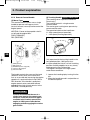
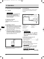
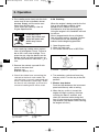
(3) Fuel System
Install the fuel pipe from the fuel tank to
the fuel pump in accordance with the
diagram.
NOTICE
When other than the specified fuel
oil is used, the engine will not
perform to full capacity and parts
may be damaged.
(1) Selection of Fuel Oil
Use diesel fuels only.
Cetane fuel number should be 45 or
greater.
GB
(2) Handling of Fuel Oil
1) Water and dust in the fuel cause engine
failure. When fuel is stored, be sure that
the inside of the storage container is
clean, and that the fuel is stored away
from dirt or rain water.
2) Keep the fuel container stationery for
several hours to allow any dirt or water
to settle to the bottom. Use a pump to
extract the clear, filtered fuel from the
top of the container for use.
Fuel system
Fuel filter
Approx. 20~30 mm
Within 500 mm
Drain cock
Fuel cock
Fuel return
To fuel injection
pump
Fuel tank
3.1.2 Lube Oil
NOTICE
Using other than the specified
lube oil will lead to seizure of
parts, abnormal wear, and shorten
engine life.
(1) Selection of Engine Lube Oil
Use the following lube oil:
• API Classification...............................CD
• SAE Viscosity ..............................15W40
Use the clear filtered fuel from the upper
middle section of the container only, leaving any
contaminated fuel at the bottom.
20
(2) Clutch Oil Selection
Use the following lube oil:
• 4JH3-TE, 4JH3-HTE Series Converter
oil for automobiles ATF-A
KBW21 Clutch
• 4JH3-TBE, 4JH3-HTBE, 4JH3-DTBE
Series and 4JH3-THE, 4JH3-HTHE,
4JH3-DTHE Series
KM4A Clutch KMH4A Clutch
API Classification............... CC or higher
SAE Viscosity........................ #20 or #30
JH-Turbo-Engels1b
28-06-2002 19:54
Pagina 21
3. Operation
(3) Handling the Lube Oil
1) When handling and storing lube oil, be
careful not to allow dust and water to
enter the lube oil. Clean around the
filter port before refilling.
2) Do not mix lube oils of different types
or brands. Mixing may cause the
chemical characteristics of the lube oil
to change and lubricating performance
to drop, reducing the engine’s life.
Before supplying lube oil to the engine
and marine gear for the first time,
extract all the lube oil already in the
tank. Use new lube oil.
3) Lube oil supplied to the engine will
undergo natural degeneration with time
even when the engine is not used.
Lube oil should be replaced at the
specified intervals, regardless of
whether the engine is being used or
not.
3.1.3 Cooling Water
It is important to check the cooling water
daily. Be sure to use clean soft water (tap
water) for cooling fresh water.
Handling of Cooling Water
1. Choose antirust which will not have any
adverse effects on the materials (cast
iron, aluminum, copper, etc.) of the
engine’s fresh water cooling system.
2. Use the proper mixing ratio of antirust
to fresh water strictly as instructed by
the antirust maker.
3. Replace the cooling water periodically,
according to the maintenance schedule
given in this operation manual.
4. Remove the scale from the cooling
water system periodically, according to
the instructions in this operation
manual.
5. Use the proper mixing ratio of
antifreeze to fresh water strictly, as
instructed by the antifreeze maker. If
too much antifreeze is used, the cooling
performance of the cooling water will
drop and the engine may become
overheated.
6. Do not mix different brands of antirust
or antifreeze.
Chemical reactions may make the
antifreeze or antirust useless and
engine trouble could result.
NOTICE
NOTICE
Be sure to add antirust or antifreeze
to cooling fresh water.
In cold seasons, the antifreeze is
especially important.
Without antirust, cooling performance
will drop due to scale and rust in the
cooling water system. Without
antifreeze, cooling water will freeze
and expand, breaking various parts.
For your reference, antifreeze mixed
with antirust is now available in the
market.
Excessive use of antifreeze also
lowers the cooling efficiency of
the engine. Be sure to use the
mixing ratios specified by the
antifreeze maker for your temperature range.
21
GB
JH-Turbo-Engels1b
28-06-2002 19:54
Pagina 22
3. Operation
3.2 Before Initial Operation
Perform the following before using the
engine for the first time:
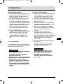
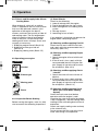
3. Move the priming pump knob up and
down until fuel mixed with air bubbles
flows out of the air bleeding bolt and
tighten the air bleeding bolt. The priming
pump is on the top of the fuel filter.
3.2.1 Supply Fuel Oil
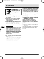
3.2.3 Supply Engine Lube Oil
DANGER
GB
Using gasoline, etc. may
cause a fire.
To avoid mistakes, be
sure to double-check the
kind of fuel before inserting. Wipe off any spilled
fuel carefully.
1. Before filling with fuel, wash out the fuel
tank and fuel system with clean
kerosene or light oil.
2. Fill the tank with clean fuel oil free of dirt
and water.
3.2.2 Bleeding the Fuel System
Bleed the fuel system according to the
following procedure. When there is air in
the fuel system, the fuel injection pump will
not be able to function.
1. Remove the filler port cap (yellow) at the
top of the bonnet, and fill with engine
oil.
2. Fill with oil to the upper limit on the
dipstick. Insert the dipstick fully to
check the level.
Engine oil capacity: See 2.2 Engine
Specifications
3. Tighten the filler port cap securely by
hand.
NOTICE
Do not overfill.
Overfilling will cause oil to be sprayed
out from breather and lead to engine
problems.
1. Open the fuel cock of the fuel tank.
2. Loosen the air bleeding bolt on the top
of the fuel filter by turning it 2~3 times.
Filler port
Bonnet
Priming pump
22
Air bleeding bolt
Dipstick
Upper limit
Lower limit
JH-Turbo-Engels1b
28-06-2002 19:54
Pagina 23
3. Operation
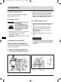
3.2.4 Supply Clutch Lube Oil
3.2.5
Supply Cooling Water
1. Remove the filler port cap at the top of
the bonnet, and fill with marine gearclutch- lube oil.
2. Fill with oil to the upper limit on the
dipstick. Insert the dipstick fully to
check the level.
Clutch oil capacity: See 2.2 Engine
Specifications
3. Tighten the filler port cap securely by
hand.
Supply cooling water according to the
following procedures. Be sure to add
antirust or antifreeze to the cooling water.
1. Be sure to close the water drain cocks.
Note: The water drain cocks are opened
before shipping from the plant.
4JH3-TE series KMH4A Clutch
NOTICE
Do not overfill.
Overfilling will cause oil to be sprayed
out during operation and affect the
efficiency of the marine gear.
GB
Fresh water
Oil filler port cap
Upper limit/Lower limit
Dipstick
Seawater
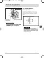
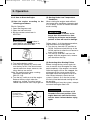
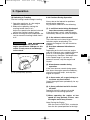
2. Remove the filler cap of the fresh water
cooler by turning the cap counterclockwise 1/3 of a turn.
Filler cap
Dents
Fresh water cooler
Notches
23
JH-Turbo-Engels1b
28-06-2002 19:55
Pagina 24
3. Operation
3. Pour cooling water slowly into the fresh
water tank so that air bubbles do not
develop. Supply until the water overflows from the filler port.
Fresh water tank capacity: See 2.2
Engine Specifications
DANGER
GB
If the filler cap is
loose, hot steam and
water will spout out
which may cause
burns.
4. After supplying cooling water, replace
filler cap and tighten it firmly. Failure to
do so will cause water leakage. To replace the cap, align the detents on the
bottom of the cap with the notches on
the filler port and turn clockwise 1/3 of a
turn.
5. Remove the subtank cap and fill with
water to the lower limit.
Replace cap.
Subtank capacity: 0.8 6. Check the rubber hose connecting the
subtank to the fresh water cooler. Be
sure the hose is securely connected and
there is no looseness or damage. When
the hose is not watertight, an excessive
amount of cooling water will be used.
To fresh water cooler
Lower limit
24
Upper limit
Cap
3.2.6 Cranking
When the engine is being used for the first
time or has not been used for a long
period of time, lube oil will not be
distributed to all of the operating parts.
Using the engine in this condition will lead
to seizure.
After a long period of disuse, distribute
lube oil to each part by cranking. Perform
in accordance with the following procedures before beginning operation.
1. Open Kingston cock.
2. Open fuel tank cock.
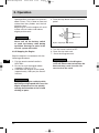
3. Put remote control lever in NEUTRAL.
Forward
Neutral
Reverse
4. Turn on battery switch and insert key
into key switch. Turn the key to the ON
position.
5. Electric stop device
Push the stop button on the instrument
panel continuously while cranking.
6. When the key switch is turned, the
engine will begin cranking. Continue
cranking for about 5 seconds, and
check for abnormal noise during that
time. (If you remove your hand from the
stop knob or stop button while cranking,
the engine will start.)
JH-Turbo-Engels1b
28-06-2002 19:55
Pagina 25
3. Operation
3.2.7 Check and Resupply Lube Oil and
Cooling Water
When engine oil, clutch oil, or cooling
water is supplied for the first time or when
they must be replaced, conduct a trial
operation of the engine for about 5
minutes and check the quantity of lube oil
and cooling water. The trial engine operation will send the lube oil and cooling
water to the parts, so the lube oil and
cooling water levels will drop. Check and
resupply as necessary.
1. Supplying engine lube oil (See 3.2.3)
2. Supplying marine gear lube oil
(See 3.2.4)
3. Supplying cooling water (See 3.2.5)
3.3 Operating your engine
WARNING
Alcohol
Exhaust gas
Moving parts
Burns
3.3.1 Inspection Before Starting
Before starting the engine, make it a daily
rule to conduct the following inspections:
(1) Visual Checks
Check for the following:
1. Lube oil leakage from the engine
2. Fuel oil leakage from the fuel system
3. Water leakage from the cooling water
system
4. Damage to parts
5. Loosening or loss of bolts
If any problem is found, do not operate the
engine before completing repairs.
(2) Checking and Resupplying Fuel Oil
Check the fuel level inside the fuel tank
and supply with the recommended fuel, if
necessary. (See 3.2.1)
(3) Checking and Resupplying Engine
Lube Oil
1. Check the engine oil level with the oil
dipstick.
2. If the oil level is low, supply with the
recommended lube oil using the filler
port. Supply oil up to the top mark on
the oil dipstick. (See 3.2.3)
GB
(4) Checking and Resupplying Clutch
Lube Oil
1. Check the clutch oil level with the oil
dipstick.
2. If the oil level is low, supply with the
recommended lube oil using the filler
port. Supply oil up to the top mark on
the oil dipstick. (See 3.2.4)
(5) Checking and Resupplying Fresh
Water (For Fresh Water Cooling
System)
Check the fresh water level before
operation while the engine is cold.
Checking the water level while the engine
is hot is dangerous, and the cooling water
reading will be misleading due to thermal
expansion.
Check and supply cooling water routinely
at the subtank only.
Do not remove the filler cap of the fresh
water tank during usual operation.
25
JH-Turbo-Engels1b
28-06-2002 19:55
Pagina 26
3. Operation
DANGER
If the filler cap is
loose, hot steam and
water will spout out
which may cause
burns.
1. Check that the cooling fresh water level
is above the lower limit on the side of
the subtank.
2. If the water level is close to the lower
limit, remove the subtank cap and
supply fresh water.
3. When the water in the subtank runs out,
remove the filler cap of the fresh water
cooler and supply water until it overflows from the filler port. (See 3.2.5)
NOTICE
GB
If the cooling fresh water runs out too
often, or only the cooling fresh water
in the fresh water tank drops without
any change in the water level of the
subtank, there may be some leakage
of water or air. In such cases, consult
your Yanmar dealer or distributor
without delay.
Note: The water rises in the subtank during
engine operation.
This is not abnormal. After stopping the
engine, the cooling water cools down
and the extra water in the subtank
returns to the fresh water tank.
26
(6) Checking the Remote Control Handle
Be sure to check that the remote control
handle lever moves smoothly before use. If
it is hard to operate, lubricate the joints of
the remote control cable and also the lever
bearings.
If the lever comes out or there is play in the
lever, adjust the remote control cable.
(See 4.3.4 (5))
(7) Preparing Fuel, Lube Oil, and Cooling
Fresh Water in Reserve
Prepare sufficient fuel for the day’s
operation. Always store lube oil and
cooling fresh water in reserve (for at least
one refill) onboard, to be ready for emergencies.
(8) Checking the Alarm Devices Electric
Operation
When operating the key switch, check that
the alarm devices work normally. (See
2.5.1 (4))
JH-Turbo-Engels1b
28-06-2002 19:55
Pagina 27
3. Operation
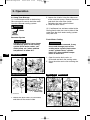
3.3.2 How to Start the Engine
(1) Start the engine according to the
following procedures:
Electric Operation
1. Open the Kingston cock.
2. Open the fuel tank cock.
3. Set the remote control lever in
NEUTRAL.
NOTICE Option
Do not leave the air heater on for
longer than 20 seconds at a time.
Leaving the air heater on for longer
periods of time will result in damage.
NOTICE
Safety equipment Option makes it
impossible to start the engine in any
other position than NEUTRAL.
4. Turn on the battery switch.
5. Insert the key into the key switch and
turn the key to ON. If the alarm buzzer
sounds and alarm lamps come on, the
alarm devices are normal.
Note: The cooling water temp. warning
lamp does not come on.
(See 2.5.1.(4))
6. Turn the key switch to start the engine.
Release the key switch when the
engine has started. The alarm buzzer
should stop and the alarm lamps go out.
OFF position
ON position
START position
GLOW position
(2) Starting Under Low Temperature
Conditions
When starting the engine under difficult
low temperature conditions (approximately
0°C or lower), use the air heater to enable
easier starting.
Follow steps 1~4 of the above procedure,
and then follow the steps below:
5. Turn the key from the OFF position to
GLOW. Continue to hold the key in the
GLOW position to allow the air heater to
warm up the engine.
6. Turn the key to START and start the
engine. After the engine starts, remove
your hand from the key.
(3) Restarting After Starting Failure
Before turning the key switch again, be
sure to confirm that the engine has stopped completely. If the engine is restarted
while the engine still has not stopped, the
pinion gear of the starter motor will be
damaged. When the engine will not start
after several attempts, check the fuel
system. If there is air in the fuel system,
the fuel will not be fed and starting will not
be possible.
After bleeding air from the system, attempt
to restart the engine. See 3.2.2
NOTICE
GLOW OFF ON
START
Turn the key for a maximum of 15
seconds in the start position. If the
engine does not start the first time,
wait for about 1 minute before trying
again.
27
GB
JH-Turbo-Engels1b
28-06-2002 19:55
Pagina 28
3. Operation
(4) After the Engine has Started
After the engine has started, check the
following items at a low engine speed:
GB
1. Check that the gauges and alarm
devices on the instrument panel are
normal.
2. Check for water or oil leakage from the
engine.
3. Check that exhaust colour, engine vibrations and sound are normal.
4. When there are no problems, keep the
engine at low speed with the boat still
stopped to send lube oil to all parts of
the engine.
5. Check that sufficient cooling water is
discharged from the seawater outlet
pipe. Operation with too small seawater
discharge will burn the impeller of the
seawater pump. If seawater discharge is
too small, stop the engine immediately.
Identify the cause and repair.
• Is the Kingston cock open?
• Is the inlet of the Kingston cock on
the hull bottom clogged?
• Is the seawater suction hose broken,
or does the hose suck in air due to a
loose joint?
NOTICE
The engine will seize if it is operated
when cooling seawater discharge is
too small or if load is applied without
any warming up operation.
28
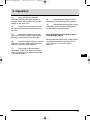
3.3.3 Operation
(1) Engine Acceleration and
Deceleration
Use the governor handle to control
acceleration and deceleration. Move the
handle slowly.
(2) FORWARD–NEUTRAL
(boat stopped) – REVERSE Clutch
Use the clutch handle to change from
FORWARD to NEUTRAL (boat stopped) to
REVERSE.
NOTICE
Shifting the clutch while operating at
high speed or not pushing the handle
fully into position (half clutch) will
result in damage to clutch parts and
abnormal wear.
1. Before using the clutch, be sure to move
the governor handle to a low speed
position (less than 1000 rpm). Move the
governor handle to a high speed position
after completing clutch operation.
2. When changing between FORWARD
and REVERSE, bring the clutch to
NEUTRAL and pause before slowly
shifting to the desired position. Do not
shift abruptly from FORWARD to
REVERSE or vice versa.
3. Move the clutch handle accurately and
fully into the FORWARD, NEUTRAL, and
REVERSE positions.
JH-Turbo-Engels1b
28-06-2002 19:55
Pagina 29
3. Operation
(3) Switching to Trawling
Use the trawling handle to begin trawling.
1. Operation continues at a low engine
speed of 1000rpm or less.
2. Reduce the speed by moving the
trawling handle from H to L.
Adjust the speed to the desired rate and
secure the trawling handle in place.
3. Before returning to normal operation, be
sure to move the trawling handle from L
to H.
NOTICE
Option KMH4A Clutch
When trawling, do not raise the
engine speed above 1000rpm, as this
results in early wear of and damage
to the clutch.
L
High speed (normal operation)
Low speed (trawling operation)
H
3.3.4 Cautions During Operation
Always be on the lookout for problems
during engine operation.
Pay particular attention to the following:
(1) Is sufficient water being discharged
from the seawater outlet pipe?
If the discharge is small, stop the engine
immediately, identify the cause and repair.
(2) Is the exhaust colour normal?
The continuous emission of black exhaust
indicates engine overloading. This
shortens the engine’s life and should be
avoided.
(3) Are there abnormal vibrations or
noise?
Depending on the hull structure, engine
and hull resonance may suddenly become
great at a certain engine speed range,
causing heavy vibrations. Avoid operation
in this speed range. If you hear any
abnormal sounds, stop the engine and
inspect.
(4) Alarm buzzer sounds during
operation.
If the alarm buzzer sounds during operation, lower the engine speed immediately,
check the warning lamps, and stop the
engine for repairs.
(5) Is there water, oil, or gas leakage, or
are there any loose bolts?
Check the engine room periodically for any
problems.
(6) Is there sufficient fuel oil in the fuel
oil tank?
Replenish fuel oil in advance to avoid
running out of fuel during operation.
7) When operating the engine at low
speed for long periods of time, race
the engine once every 2 hours.
Note: Racing the Engine
With the clutch in NEUTRAL, accelerate
from the low speed position to the high
29
GB
JH-Turbo-Engels1b
28-06-2002 19:55
Pagina 30
3. Operation
speed position and repeat this process
about 5 times. This is done to clean out
carbon from the cylinders and the fuel
injection valve.
Neglecting to race the engine will result
in poor exhaust colour and reduce
engine performance.
4. Push the stop button on the instrument
panel.
Stop button on the instrument panel
NOTICE
Electric Operation
Never turn off the battery switch
or spark the battery cable during
operation. Damage to parts in the
electric system will result.
3.3.5 Stopping the Engine
Stop the engine in accordance with the
following procedures:
GB
1. Put the remote control handle in
NEUTRAL.
2. Be sure to race the engine before
stopping it. (See 3.3.4 (7))
3. Cool down the engine at low speed
(approximately 1000 rpm) for about 5
minutes.
NOTICE
Stopping the engine suddenly while
operating at high speed will cause the
engine temperature to rise quickly,
causing deterioration of the oil and
sticking of parts.
30
Engine stopping by stop button
5. Turn the starter switch to OFF.
6. Close the fuel tank cock.
7. Close the Kingston cock.
NOTICE
Neglecting to close the Kingston
cock will allow water to leak into the
boat and may cause it to sink. Be
sure to close the cock.
JH-Turbo-Engels1b
28-06-2002 19:55
Pagina 31
3. Operation
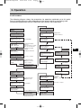
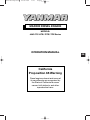
3.3.6 Procedure
The following diagram shows the procedures for operation explained up to this point.
Parts of the operation may differ depending on the remote control system being used.
Accompanying operation manuals should be read carefully and understood.
Starting Operation
Inspection Before
Starting
Driving Device Clutch
Clutch Remote Control
Lever
Starting the Engine
Driving Device Clutch
Clutch Remote Control
Lever
Starter Switch
OFF ON
ON START
ON
Alarm Lamps
Instrument Panel
Put in NEUTRAL
• Checking the Alarm
Devices
• Turn the key for no longer
than 15 secs. Remove
hand from key after
starting.
Checking for Problems
Warming-up Operation
For 5 mins. or longer
Speed Lever
Govenor Remote Control
Handle
Low Speed Position
1000rpm or lower for
5 mins. or longer
Engage Clutch
Forward or Reverse
Speed Lever
Govenor Remote
Control Handle
Adjust Speed
Speed lever
Governor Remote
Control Handel
Low Speed Position
1000rpm or lower
Driving Device Clutch
Clutch Remote Control
Lever
KMH4A Clutch
Trawling
Forward or
Reverse
Speed Lever
Govenor Remote
Control Handle
Trawling Handle
Trawling Lever
Low Speed
Adjust speed
Checking the Engine
During Operation
Return to Normal
Operation
Stopping the Boat/
Preparing to Stop the
Engine
Trawling Handle
Trawling Lever
Speed Lever
Govenor Remote
Control Handle
Low Speed Position
1000rpm or lower
Driving Device Clutch
Clutch Remote Control
Lever
Put in Neutral
Speed Lever
Govenor Remote
Control Handle
High Speed
Speed lever
Governor Remote
Control Handle
Low Speed
Position
1000rpm or lower
Cooling-down Operation
For 5 mins. or longer
Engine Stop Button
Low Speed High Speed
Racing the Engine
Engine Stops
Repeat Several Times
31
GB
JH-Turbo-Engels1b
28-06-2002 19:55
Pagina 32
3. Operation
3.4 Long Term Storage
(1) In cold temperatures or before long
term storage, be sure to drain the water
from the seawater cooling system.
2. Loosen the 4 bolts fixing the side cover
of the seawater pump, remove the cover
and drain the water from inside.
Retighten the bolts when finished.
3. Close the drain cocks.
CAUTION
(2) If antifreeze has not been added to the
cooling fresh water, be sure to drain off the
water from the fresh water cooling system
daily after use.
Burns
Seawater System
Fresh Water Cooling
NOTICE
If water is left inside, it may freeze
and damage parts of the cooling
system (fresh water cooler, seawater pump, etc.) when ambient
temperature is below 0°C.
GB
4JH3-TE Series
NOTICE
If the water is not removed, it may
freeze and damage parts of the
cooling water system (fresh water
cooler, cylinder block, cylinder
head, etc.) when ambient temperature is below 0°C.
1. Open the water drain cocks as
illustrated and drain the cooling water.
2. Close the drain cocks after draining the
water.
4JH3-TE series KMH4A Clutch
4JH3-HTE/DTE Series
Seawater
1. Loosen the drain cocks as illustrated,
and drain off the water inside.
Fresh water
32
JH-Turbo-Engels1b
28-06-2002 19:55
Pagina 33
3. Operation
(3)
Carry out the next periodic
inspection before placing the engine in
storage. Clean the outside of the engine
wiping off any dust or oil.
(4)
To prevent condensation inside
the fuel tank, either drain off the fuel or fill
the tank.
(5)
Grease the exposed area and
joints of the remote control cable and the
bearings of the remote control handle.
(6)
Cover the intake silencer, exhaust
pipe, etc. with vinyl sheets and seal them
to prevent moisture from entering.
(8)
Waterproof the engine room to
prevent rain and seawater from entering.
(9)
During long term storage, charge
the battery once a month to compensate
for the battery’s self-discharge.
Checking the Engine for Reuse After a
Long Storage Period
When using the engine after a long period
of storage, prepare for operation in the
same manner as for a new engine.
See 3.3.1
(7)
Drain bilge in the hull bottom
completely. Water may leak into the boat
when it is moored, and whenever possible
it should be landed.
GB
33
JH-Turbo-Engels1b
28-06-2002 19:55
Pagina 34
4. Maintenance & Inspection
4.1 General Inspection Rules
Conduct Periodic Inspection for Your
Safety.
The functions of engine components will
degenerate and engine performance will
drop according to the use of the engine. If
countermeasures are not taken, you may
encounter unexpected troubles while
cruising at sea. Consumption of fuel or
lube oil may become excessive and
exhaust gas and engine noise may
increase. These all shorten the life of the
engine. Daily and periodic inspection and
servicing increase your safety at sea.
Inspect Before Starting.
Make it a daily rule to inspect before
starting. (See 3.3.1)
GB
Periodic Inspections at Fixed Intervals.
Periodic inspections must be made after
every 50 hrs., every 250 hrs (1 yr.), every
500 hrs. (2 yrs.), every 1000 hrs. (4 yrs.) of
use. Conduct periodic inspections
according to the procedures described in
this Operation Manual.
Use Genuine Parts.
Be sure to use genuine parts for
consumable and replacement parts.
Use of other parts will reduce engine
performance and shorten the life of the
engine.
Consult Your YANMAR Dealer or
Distributor.
Specialized technicians are ready to assist
you with periodic inspections and maintenance. Consult your YANMAR dealer or
distributor in accordance with the service
agreement.
Servicing Tools
Prepare servicing tools onboard to be
ready for inspecting and servicing the
engine and other equipment.
Tightening Torque of Bolts & Nuts
Over-tightening of bolts and nuts causes
them to come off or their threads to be
damaged. Insufficient tightening causes oil
leakage from the installation face or
troubles due to the loosening of bolts.
Bolts and nuts must be tightened to the
appropriate tightening torque. Important
parts must be tightened with a torque
wrench to the correct tightening torque
and in the right order. Consult with your
dealer or distributor if the servicing
requires the removal of such parts.
The standard tightening torque for
standard bolts & nuts is listed below.
NOTICE
Apply the following tightening torque to bolts having “7” on the head. (JIS strength
classification: 7T)
Tighten bolts with no “7” mark to 60% tightening torque.
If the parts to be tightened are made from light alloy aluminum, tighten the bolts to 80%
tightening torque.
Bolt dia. × pitch mm
M6×1.0
M8×1.25
M10×1.5
M12×1.75
M14×1.5
M16×1.5
Tightening torque Nm
11 ± 01
26 ± 03
50 ± 05
90 ± 10
140 ± 15
230 ± 20
34
JH-Turbo-Engels1b
28-06-2002 19:55
Pagina 35
4. Maintenance & Inspection
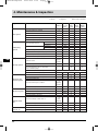
4.2 List of Periodic Inspection Items
Daily and periodic inspections are
important to keep the engine in its best
condition. The following is a summary of
inspection and servicing items by
inspection interval. Periodic inspection
intervals should vary depending on the
uses, loads, fuels and lube oils used and
handling conditions, and are hard to
establish definitively. The following should
be treated as a general standard only.
Section 4.3 gives a detailed explanation of
which parts must be inspected and the
procedure for doing so for each interval.
GB
35
JH-Turbo-Engels1b
28-06-2002 19:55
Pagina 36
4. Maintenance & Inspection
: Replace
❍: Check
System
Item
Before
starting
After 50
Every
Every
Every
hrs or one 250 hrs 500 hrs 1000 hrs
month
(1 year) (2 years) (4 years)
❍
Check the fuel level, and refill
Fuel system
●: Consult local dealer
Drain the fuel tank
❍ (first)
Drain the fuel filter
❍
❍
Replace the fuel filter
●
Check the injection timing
❍
Check the injection spray condition
Check the lube oil level
Lubricating
system
GB
Crankcase
❍
Marine gear
❍
Replace the engine lube oil filter
(first)
(first)
(first)
Wash the lube oil filter (Marine gear)
❍ (first)
❍
Replace the lube oil
Crankcase
Marine gear
Clean the engine oil cooler
●
Clean the oil cooler (Marine gear)
●
Seawater outlet
Cooling system
❍
Check cooling water level
❍
During
operation
❍
Check the impeller of the cooling water
pump (seawater pump)
❍
Every year
Replace the fresh water cooling
●
Clean & check the water passages
Air intake and
exhaust system
Clean the element of the air intake silencer
❍
Clean the exhaust/water mixing elbow
❍
Clean the breather pipe
❍
Check the exhaust gas condition
❍
During
operation
❍
Wash turbocharger blower
Check the alarm lamps & devices
Electrical system
❍
❍
Check the electrolyte level in the battery
❍ (first)
Adjust the tension of the alternator driving belt
Check for leakage of water and oil
Cylinder head,
etc.
36
❍
(After
starting)
●
Retighten all major nuts and bolts
❍ (first)
Adjust intake/exhaust valve clearance
Remote control
system, etc.
❍
❍
Check the wiring connectors
Check/adjust the remote control operation
Adjust the propeller shaft alignment
❍
●
❍
❍ (first)
❍
JH-Turbo-Engels1b
28-06-2002 19:55
Pagina 37
4. Maintenance & Inspection
4.3 Periodic Inspection Items
CAUTION
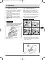
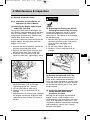
4.3.1 Inspection on Initial 50 Hrs. of
Operation (or after 1 Month)
(1) Replacing the Engine Lube Oil and
Lube Filter (1st time)
During initial operation of the engine, the
oil is quickly contaminated due to the initial
wear of internal parts. The lube oil must
therefore be replaced early. Replace the
lube oil filter at the same time.
It is easiest and most effective to drain the
engine lube oil after operation while the
engine is still warm.
1. Remove the lube oil dipstick. Attach the
oil drain pump and drain off oil.
2. Remove the lube oil filter with the filter
detach/attach tool. (Turn to the left.)
3. Clean the filter installation face and
attach the new filter, tightening by hand.
4. Turn an additional 3/4 of a turn with the
attachment tool. (Turn to the right.
Tightening torque: 20 ~ 24 Nm)
5. Fill with new lube oil. (See 3.2.3)
6. Perform a trial run and check for oil
leakage.
7. Approximately 10 minutes after stopping
the engine, remove the oil dipstick and
check the oil level. Add oil if the level is
too low.
Burns
(2) Replacing the Clutch Lube Oil and
Cleaning the Clutch Filter (1st time)
During initial operation, the oil is quickly
contaminated due to the initial wear of
internal parts. The lube oil must therefore
be replaced early.
1. Remove the cap from the filler port and
attach the oil drain pump. Drain off oil.
Clean the filter thoroughly with
kerosene.
2. Fill with new lube oil. (See 3.2.4)
3. Perform a trial run and check for oil
leakage.
GB
KMH4A
(3) Draining the (optional) Fuel Tank
Open the drain cock and drain off any
water or dirt collected on the bottom.
Put a pan under the drain to catch the fuel.
Once the water and dirt has been drained
off and the fuel coming out is clear, close
the drain cock.
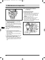
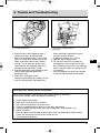
(4) Inspection and Adjustment of
Intake/ Exhaust Valve Head
Clearance (1st time)
Settling of a new engine and individual
engine use will cause changes in the
intake/exhaust valve and rocker arm clearance, and adjustment is necessary. This
adjustment requires specialized knowledge
and techniques. Consult your Yanmar
dealer or distributor.
37
JH-Turbo-Engels1b
28-06-2002 19:56
Pagina 38
4. Maintenance & Inspection
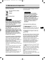
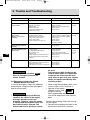
4.3.2 Inspection Every 50 Hours
(or Monthly)
(1) Draining the Fuel Filter
1. Close the fuel oil cock.
2. Loosen the plug screw at the bottom of
the fuel filter oil/water separator, and
drain off any water and dirt collected
inside.
Retighten the plug screw.
3. After reassembly, be sure to vent air
from the fuel system. (See 3.2.2)
4. When there is a heavy deposit, drain the
fuel tank at the same time.
GB
(5) Adjusting the Tension of the Alternator Driving Belt.
When there is not enough tension in the Vbelt, the alternator will not turn and power
will not be generated.
When there is too much tension in the Vbelt, the belt will become damaged more
quickly, and the alternator bearing may be
damaged.
1. Check the tension of the V-belt by
pressing down on the middle of the belt
with your finger.
With proper flexion, the V-belt should
sink 8~10mm.
2. Loosen the set bolt and move the alternator to adjust V-belt tension.
3. Be careful not to get any oil on the Vbelt. Oil on the belt causes slipping and
stretching. Replace the belt if it is marred.
38
JH-Turbo-Engels1b
28-06-2002 19:56
Pagina 39
4. Maintenance & Inspection
(2) Electric Operation
Fire due to Electric ShortCircuits
Battery
Battery Fluid
WARNING
Before inspecting the electrical system,
be sure either to turn off the battery
switch or to disconnect the (-) terminal
of the earth cable. Otherwise, a shortcircuit could cause a fire.
Ensure good ventilation when charging
the battery. The use of open flames is
strictly prohibited. Hydrogen gas may
also catch fire.
Battery fluid is diluted sulfuric acid. It
can blind you or burn your eyes or skin.
Wear goggles and gloves when handling
battery fluid. Should the fluid be
deposited on your skin, wash with a
large quantity of fresh water and seek
treatment from a doctor.
1) If operation continues with insufficient
battery fluid, the battery will be destroyed.
Check the fluid level periodically. If the
level is lower than specified, resupply
battery fluid (available in the market) up to
the upper limit of the battery.
(Battery fluid tends to evaporate in high
temperatures, especially in summer. In
such cases, inspect the battery earlier than
specified.)
2) If the engine speed will not rise and the
engine cannot be started, measure the
specific gravity with a pycnometre (available in the market).
The specific gravity of the fluid when fully
charged is over 1.27(at 20°C).
Fluid with a specific gravity of below 1.24
needs charging. If the specific gravity
cannot be raised by charging, the battery
must be replaced.
NOTICE
The capacities of the standard
alternator and the recommended
battery assume only the power
necessary for regular operation.
If the power is also used for inboard
lighting or other purposes, the
generating and charging capacities
may be insufficient. In such cases,
consult your Yanmar dealer or
distributor.
4.3.3 Inspection Every 250 hours.
(1) Replace the engine oil and the
clutch lube oil.
After the second oil change, the engine oil
should be replaced after every 250 hours.
(2) Replacing the Engine Oil and Lube
Oil Filter
(See 4.3.1(1))
(3) Adjusting the Remote Control Cable
The various control levers on the engine
side are connected to the remote control
lever by the remote control cable. The
cable will become stretched and the
attachments loose after long hours of use
causing deviation. It is dangerous to
control operation under these conditions,
and the remote control cable must be
checked and adjusted periodically.
A) Adjusting the Governor Remote Control
Cable
Check to see that the control lever on the
engine side moves to the high speed bolt
position and low speed bolt position when
the remote control lever is moved to
H (high speed) and L (low speed) respectively.
When there is deviation, loosen the
bracket for the remote control cable on the
engine side and adjust.
39
GB
JH-Turbo-Engels1b
28-06-2002 19:56
Pagina 40
4. Maintenance & Inspection
Adjust the high speed bolt position first
and then adjust the low speed idling.
(5) Cleaning the Intake Silencer
Disassemble the intake silencer and clean
the inside thoroughly.
Remove the cover by taking off the clamp.
Clean the element with a neutral detergent.
Reassemble after it is completely dry.
Marine gear Cable Adjustment
GB
B) Adjusting the Clutch Remote Control
Cable
Check to see that the control lever moves
to the correct position when the remote
control handle is put in NEUTRAL,
FORWARD, REVERSE.
Use the NEUTRAL position as the standard for adjustment. When there is deviation, loosen the bracket for the remote
control cable on the clutch side and
adjust.
Speed lever Low speed High speed
(4) Replacing the Fuel Filter
When there is dirt in the fuel, the filter becomes clogged, and the fuel will not flow
easily. Check and replace the inside
element.
40
1. Close the fuel cock.
2. Remove the filter case by loosening the
retainer ring (turn to the left) with the
filter wrench.
3. Pull the element out from the bottom,
and replace with a new one.
4. Clean the inside of the case thoroughly,
put on the O-ring, and close with the
retainer ring. (Turn to the right.
Tightening torque: 12 Nm)
5. Air will enter into the fuel system when
the filter is disassembled, and should be
vented. (See 3.2.2)
(6) Adjusting the Tension of the
Alternator Driving Belt
(See first 50 hrs.)
JH-Turbo-Engels1b
28-06-2002 19:56
Pagina 41
4. Maintenance & Inspection
(7) Inspecting Inner Parts of the Seawater Pump
Depending on the use, the inside parts of
the seawater pump deteriorate and discharge performance drops. At the
specified interval or when the volume of
seawater discharged is reduced, inspect
the seawater pump in accordance with the
following procedures:
1. Loosen the side cover set bolts and
remove the side cover.
2. Illuminate the inside of the seawater
pump with a flashlight and inspect.
3. If any of the following problems is
found, disassembly and maintenance
are necessary:
a) Impeller blades are cracked or nicked.
Edges or surfaces of the blades are
marred or scratched.
Note: The impeller must be replaced
periodically (every 1000 hrs.).
b) Wear plate is damaged.
4. If no damage is found when inspecting
the inside of the pump, reassemble the
side cover.
Fit the O-ring to the groove of the joint
face before replacing the side cover.
If a large amount of water leaks
continuously from the water drain pipe
beneath the seawater pump during
operation, disassembly and maintenance
(replacement of the oil seal) are
necessary.
When disassembly and maintenance of
the seawater pump are necessary, consult your Yanmar dealer or distributor.
NOTICE
The seawater pump turns in the
counterclockwise direction, but the
impeller must be installed by turning
in the clockwise direction. If the
impeller has been removed for any
reason and must be reassembled, be
very careful not to make a mistake
and turn it in the wrong direction.
Additionally, if the engine is being
turned manually, be careful to turn it
in the correct direction. Incorrect
turning will twist the impeller and
damage it.
(8) Washing the Turbocharger Blower
When engine revolution seems sluggish or
the exhaust colour poor, the blades of the
turbocharger blower may be dirty. Wash
the blower in the following manner:
1. Have ready blower wash (liquid
detergent), fresh water, and a small
pitcher.
2. Put the clutch in neutral and run the
engine at high speed (2500~3000rpm).
3. Slowly pour approximately 50cc of
blower wash into the turbocharger
suction inlet over a period of about
10 seconds.
NOTICE
Do not pour in a large amount of
blower wash at one time (pour it in
gradually) as this can damage the
blower blades and get water hammer
in the combustion chamber leading to
accidents.
4. After about 3 minutes, pour in
approximately 50cc of fresh water in the
same manner over a period of about
10 seconds.
41
GB
JH-Turbo-Engels1b
28-06-2002 19:56
Pagina 42
4. Maintenance & Inspection
Adjustment requires specialized knowledge and techniques. Consult your Yanmar dealer or distributor.
(5) Adjusting the Remote Control Cable
(See 4.3.2(3))
4.3.5 Inspection Every 1000 hrs.
Blower wash
GB
Inlet
5. After operating the engine for about
10 minutes, check the boost pressure
and power output.
If there is no improvement after washing
the blower, repeat the washing process
several times.
If there is still no improvement consult
your local Yanmar dealer.
4.3.4 Inspection every 500 hrs.
(1) Draining the fuel tank.
(See first 50 hrs.)
(2) Inspecting and Adjusting the Fuel
Injection Spray Condition.
Adjustment is necessary to obtain the
optimal fuel injection to ensure the best
possible engine performance. This inspection requires specialized knowledge and
techniques. Consult your Yanmar dealer or
distributor.
(3) Replace Driving Belt
(See first 50 hrs.)
(4) Inspection and Adjustment of Intake/
Exhaust Valve Clearance.
When operating for long periods of time,
the clearance between the intake/exhaust
valve and the rocker arm will change and
affect operation performance. Adjustment
is necessary.
42
(1) Inspecting and Adjusting the Fuel
Injection Timing
Fuel injection timing must be adjusted to
ensure optimal engine performance.
This maintenance requires specialized
knowledge.
Consult your Yanmar dealer or distributor.
(2) Washing the Cooling Water System
and Checking and Maintaining Parts
This maintenance requires specialized
knowledge. Consult your Yanmar dealer or
distributor. Over time rust and scale builds
up in the seawater and fresh water
systems, reducing their cooling
performance. Additionally, when the inside
of the engine oil cooler and the clutch oil
cooler become dirty, lube oil cooling
worsens causing the oil to deteriorate
more quickly.
Wash the following related parts when the
cooling water is being replaced.
Cooling water system related parts:
seawater pump, engine oil cooler, clutch
oil cooler, fresh water pump, fresh water
cooler, thermostat, etc.
(3) Replace Impeller of Seawater Pump
(See 250 hrs.)
JH-Turbo-Engels1b
28-06-2002 19:56
Pagina 43
5. Trouble and Troubleshooting
5.1 Trouble and Troubleshooting
Trouble
Alarm Buzzer and Alarm
Lamps On During
Operation
Probable Cause
Measure
Reference
NOTICE
Shift to low speed operation immediately, and check which lamp has come on. Stop
the engine for inspection. If no abnormality is identified and there is no problem with
operation, return to port at your lowest speed and request repairs.
Eng.Lube Oil Press.
Warning Lamp goes on
Engine Lube Oil insufficient;
Fuel filter clogged.
Check Lube Oil level.
Replenish or replace.
3.2.3
4.3.1(1)
C.W.Temp.(Fresh Water)
warning lamp goes on
Insufficient water in fresh water cooler.
Insufficient seawater causing temp. to
rise.
Contamination inside cooling system.
Check cooling water and replenish.
Check seawater system.
Ask for repairs.
3.2.5
Faulty Warning Devices
NOTICE
Do not operate the engine if alarm devices are not repaired.
Serious accidents may result if difficulties are not spotted due to faulty alarm lamps.
When switch is turned ON:
Alarm buzzer does not sound. Circuit broken or buzzer defective. Ask for repairs.
C.W. Level Alarm Lamp
goes on
Insufficient cooling water in fresh water
tank.
Check and replenish fresh cooling
water.
3.2.5
Fuel Filter Alarm Lamp
goes on
Increased fuel filter drain.
Drain the fuel filter.
4.3.2(1)
Exhaust Alarm Lamp goes
on
Insufficient discharge of cooling
seawater.
Damaged cooling seawater pump.
Kingston cock is closed.
Kingston cock is clogged.
Suction hose is damaged or joints
are loose.
Check seawater pump impeller.
4.3.3(7)
One of the warning lamps
does not go out
Sensor switches faulty.
Ask for repairs.
Charge lamp does not go
out during operation
(Buzzer does not sound)
V-belt is loose or broken.
Battery defective.
Alternator power generator failure.
Replace V-belt; adjust tension.
Check fluid level, specific gravity;
replace.
Ask for repairs.
GB
4.3.1(3)
4.3.2(4)
*Note: Other warning lamps do not go on when the switch is turned on. They only go on when there is an abnormality.
43
JH-Turbo-Engels1b
28-06-2002 19:56
Pagina 44
5. Trouble and Troubleshooting
Trouble
Probable Cause
Measure
Reference
Starter turns, but engine
does not start
No fuel.
Fuel filter is clogged.
Improper fuel.
Faulty fuel injection.
Compression leakage from
intake/exhaust valve.
Replenish fuel; vent air.
Replace element.
Replace with recommended fuel.
Ask for repairs.
Ask for repairs.
3.2.2
4.3.4(1)
Starter does not turn or
turns slowly
(Engine can be turned
manually)
Faulty clutch position.
Insufficient battery charge.
Cable terminal contact failure.
Faulty safety switch device.
Faulty starter switch.
Power lacking due to other use.
Shift to NEUTRAL and start.
3.3.2(1)
Check fluid lever; recharge; replace. 4.3.2(4)
Remove rust from terminal; retighten.
Ask for repairs.
Ask for repairs.
Ask for repairs.
Consult your dealer.
Engine cannot be turned
manually
Internal parts seized; broken.
Ask for repairs.
Abnormal Exhaust Colour
Black smoke
Load increased.
Contaminated intake silencer.
Boost pressure low.
Improper fuel.
Faulty spraying of fuel injection valve.
Incorrect intake/exhaust valve head
clearance.
Inspect propeller.
Clean element.
Wash turbocharger blower.
Replace with recommended fuel.
Ask for repairs.
Ask for repairs.
White smoke
Improper fuel.
Faulty spraying of fuel injection valve.
Fuel injection timing off.
Lube oil burns; excessive consumption.
Ask for repairs.
Ask for repairs.
Ask for repairs.
Ask for repairs.
Starting Failures
GB
NOTICE
When the clutch is broken KMH4A :
See 5.2, Emergency Repairs for
Clutch Trouble.
5.2 Emergency Repairs for Clutch.
KMH4A Marine Gear Only
In case of emergency, follow the following
procedure for using the clutch emergency
bolt to return to port.
NOTICE
• Using the emergency bolt directly
connects the clutch to the engine
making it possible to turn the
propeller. However, when the engine
is started and the propeller turns, the
boat will only move forward. The
neutral and reverse positions cannot
44
4.3.4(4)
4.3.3(8)
3.1.1
3.1.1
be used.
The emergency bolt should only be
used in cases where it is impossible
to operate the clutch and the boat
must return to port. Ask your Yanmar
dealer for repairs immediately after
returning to port.
• When using the emergency bolt, never
use the clutch as this will break it.
• Operate at low speed,
1000rpm or less, and
navigate carefully.
When approaching the pier
turn off the engine early and stop the
boat.
Perform the following steps after turning
off the engine:
1. Remove the hexagonal red bolts at the
back of the clutch with a spanner.
JH-Turbo-Engels1b
28-06-2002 19:56
Pagina 45
5. Trouble and Troubleshooting
Turning stick direction
Emergency bolt tightening tool
Bolt (red)
2. Check to see if the emergency bolt is
visible at the back of the bolt hole.
When the emergency bolt is not visible,
insert a turning stick little by little in the
holes at the front side of the V-pulley,
turning it in the direction of the crank
shaft rotation and stopping when the
emergency bolt becomes visible.
3. Inset the emergency bolt tightening tool
into the bolt hole and tighten the
emergency bolt.
4. There are 2 emergency bolts.
Follow the procedure described in 2 and
3 for the second bolt, and tighten the
bolts alternately applying the same
amount of force to each.
(Tightening torque: 19 ~ 01 Nm)
5. Replace the hexagonal bolt.
6. Fill with the clutch oil set aside for
emergencies to the mouth of the filler
port. (When the oil pump is not working,
there is no lubrication and filling with oil
is essential.)
7. Start the engine with the clutch handle
in neutral and proceed at low speed.
Consulting Your Yanmar Dealer or Distributor
Refer difficult problems and repairs to your Yanmar dealer or distributor.
At the time of trouble, check and report the following:
1.
2.
3.
4.
5.
6.
Engine model and number:
Boat name, material of hull, size (tons):
Use, type of fishing done, no. of hours run:
Total no. of operation hours (refer to hour metre), age of boat:
Condition before trouble (engine rpm, type of operation, load condition, etc.):
Details of trouble:
(exhaust colour; sound of engine; does engine start; can engine be turned manually;
type of fuel used; brand and viscosity of lube oil; etc.)
7. Past problems and repairs:
45
GB
JH-Turbo-Engels1b
28-06-2002 19:56
Pagina 46
5. Trouble and Troubleshooting
WARRANTY SERVICE
Owner Satisfaction
Your satisfaction and goodwill are
important to us and to your dealer.
Normally any problems concerning the
product will be handled by our dealer’s
service department. If you have a warranty
problem that has not been handled to your
satisfaction, we suggest you take the
following action:
• Discuss your problem with a member of
the dealership management.
Complaints can often quickly be
resolved at this level. If the problem has
already been reviewed with the Service
Manager, contact the owner of the
dealership or the General Manager.
GB
• If your problem still has not been
resolved to your satisfaction, contact
your local Yanmar Subsidiary Company. (See the back of this manual for
addresses)
46
We will need the following information in
order to assist you:
• Your name, address and telephone
number
• Product model and serial number
• Purchase date
• Dealer’s name and address
• Nature of the problem
After reviewing all the facts involved, you
will be advised of what action can be
undertaken. Please remember that your
problem will most likely be resolved at the
dealership, using the dealer’s facilities,
equipment and personnel. It is therefore
very important that your initial contact be
with the dealer.
JH-Turbo-Engels1b
28-06-2002 19:56
Pagina 47
6. Piping diagram
(See appendix A at the back of this book)
NOTATION
RH
Rubber hose
SGP STS
Steel pipe
C1201T
Copper pipe
Screw joint (Union)
Flange joint
Eye joint
Insertion joint
Drill hole
Cooling fresh water
piping
Cooling seawater piping
Lubricating oil piping
Fuel oil piping
01
02
03
04
05
06
07
08
09
10
11
12
13
14
15
16
17
18
19
20
21
22
23
24
25
26
27
Overflow
Fuel oil inlet
Piston cooling oil jet
Fuel injection pump
Lub. oil filter (cartridge type)
Fuel high pressure pipe
Fuel injection nozzle
Oil pressure switch
Lub. oil cooler
Mixing elbow
Fresh water cooler
Lub. oil inlet filter
Main bearing
Seawater inlet
Cooling water pump (seawater)
Hot water connection outlet
Thermostat
Cooling water pump (fresh
water)
Hot water connection inlet
Fresh water temperature
switch
Lub. oil pump
Pressure control valve
Clutch lube oil cooler
Turbo charger
Seawater outlet
Air cooler*
Fuel oil filter (cartridge type)
NOTES:
Dimension of steel pipe:
outer dia.x thickness
Dimension of rubber pipe:
inner dia. x thickness
Note: This piping diagram is for the
4JH3E model.
GB
* Not applicable (for the TE-model)
47
JH-Turbo-Engels1b
28-06-2002 19:56
Pagina 48
7. Wiring diagrams
(See appendix B at the back of this book)
Colour coding for wiring
diagrams
R
GB
Red
B
Black
W
White
Y
Yellow
L
Blue
G
Green
O
Orange
Lg
Light green
Lb
Light blue
Br
Brown
P
Pink
Gr
Grey
Pu
Purple
For B/C-type panel
01 Starter switch
02 Stop switch
03 Switch (lamp chk/illum.)
04 Relay
05 Relay (optional)
06 Engine stop solenoid (optional)
07 Procured by customer
08 (Cross sectional area)
09 Battery switch
10 Battery
11 Air heater
12 Starter relay*
13 Starter
14 Cooling water temperature
switch
15 Engine oil pressure switch
16 Alternator
17 Earth bolt
18 Not applicable
19 Tachometre sensor
20 (Cooling water temperature
sender)
21 Engine oil pressure sender
22 Wire harness for 2 panel
(optional)
23 Wire harness (optional)
24
25
26
27
28
29
30
31
32
33
34
35
36
37
38
39
40
41
42
43
44
45
46
47
48
49
Option
Instrument panel
Buzzer
Tachometre
Not applicable
Oil pressure
Cooling Fresh Water temp.
Charge
Switch (lamp chk/illum.)
Starter switch
Stop switch
Instrument panel
(No.2 station)(optional)
Tachometre
Buzzer
Water proof
Oil pressure
Cooling Fresh Water temp.
Charge
Buzzer switch
FUSE (3A)
Eng. oil pressure metre
Cooling water temp. metre
Hour metre
Illumination switch
Cooling water temp.
Eng. oil pressure
* Note: When using extension wireharnesses of more than 6m, the starter
relay connection is as shown here.
48
•
•
•
•
•
MANUFACTURER’S DECLARATION FOR MACHINERY PARTS ACCORDING TO 94/25/EEC(ANNEX-15) & 89/336/EEC
MANUFACTURER:
YANMAR CO., LTD.
1-32, Chayamachi, Kita-ku, Osaka, Japan
DESCRIPTION OF THE MACHINERY PARTS
CATEGORY: Diesel engine
1.
MAKE: YANMAR
2.
THIS MACHINERY PART MUST NOT BE PUT INTO SERVICE UNTIL THE MACHINERY INTO WHICH IT IS TO BE INCORPORATED HAS
BEEN DECLARED IN CONFORMITY WITH THE PROVISIONS OF THE DIRECTIVE.
IMPORTER IN THE EU:
YANMAR MARINE INTERNATIONAL B.V.
Brugplein 11
1332 BS Almere-de Vaart, The Netherlands
Nagahama, Japan, Sept. 21, 1997
Place and date issued
Y. Sugita
Manager
Quality Assurance Dept.
Power System Operation Div.