1
2 2 2
HARTREY
AVE.,
EVANSTON,
IL.
6 0 2 0 4
U.S.A.
GENERAL
The Shure M675 Broadcast Production Master is designed for use in conjunction with a Shure M67 or
M67-2E Professional Microphone Mixer, M63 Audio
Master, or SE30 Gated Compressor/Mixer. The combination of the two units provides a complete, compact
console permitting mixing of a number of microphones,
high level sources (such as tape or tape cartridge or
cassette machines) and turntables. By making an internal jumper change, the two phono inputs may be
used for tape head or high impedance microphone
inputs.
The M675 is not a complete mixer in itself. It may be
thought of as two separate sections: a four-input mixer,
and a monitor amplifier and speaker. The mixer section adds four more inputs to the M67, M63 or SE30.
Two inputs are line level (switchable to "Bridge" or
"Terminate"), and the other two are switchable between "Phono" (RIAA equalized preamplifier) and
"Bridging" line level.
The primary purpose of the monitor amplifier and
speaker section of the M675 is to allow the operator
to audibly monitor the output of the M67, M63 or SE30.
Note that the output of the associated mixer consists
of its own signals plus those from the M675 inputs.
The M675 speaker reproduces the M67, M63 or SE30
output signal, and the M675 "Monitor" control adjusts
the speaker volume. A second function of the M675
monitor amplifier and speaker is to "cue" or preview
the signals entering the M675 mixer section without
having these signals appear at the M67, M63 or SE30
output. This is accomplished using the "Cue" position
of the appropriate M675 "lnput" control knob.
NOTE: Except as noted, references to M67 refer also
to operation with M63 or SE30.
Features
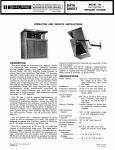
m Provides a complete compact portable production
console when used with M67 or other Shure Microphone Mixers.
Adds four channels with cue provision, when used
with the M67.
Powered by either internal batteries (popular 9V
type) or by M67. Can also provide battery voltage
for powering M67.
Operator can hear program material at a reduced
level during cuing.
Wide flat frequency response and low distortion.
Extremely low noise and RF susceptibility.
Four balanced line inputs with individual gain controls.
Two line inputs switchable to magnetic phono inputs
(RIAA equalization).
AREA
CODE
3121328-9000
CABLE:
SHUREMICRO
Convertible line inputs are switchable at front panel.
Two line inputs are switchable between high impedance, bridging, or 600-ohm terminating.
Front-panel 600-ohm headphone output jack for
program monitor and cue. Rear panel headphone
output jack for program monitor.
External &ohm speaker output jack for monitoring
program and cue, with provision for external muting.
Internal monitor speaker for program and cue.
All connections are phase-matched to M67.
Compact, lightweight.
Stacking hardware included for mounting M675 to
M67.
SPECIFICATIONS
Frequency Response:
Program Channel (measured at M67 output):
phono: t 2 dB of standard RIAA
line:
+2 dB, 30-20 kHz
Monitor Channel: response tailored to - 5 dB @ 40 Hz,
- 3 dB @ 15 kHz.
Gain at 1 kHz:
A. Program Channel:
Mix Bus Output
(with 3.5k load)
M67 Output
+13.5&2dB
+83.5-+2dB
-29
k 2 dB
+ 4 1 t 2 dB
Line 3 , 4 bridge
-29
f 2 dB
+41 * 2 dB
Line 3, 4 terminate
-35
t 2 dB
+35 t 2 dB
Input
Phono
Line 1, 2
NOTE: Gain to Mix Bus output will b e approximately 13 dB higher
than shown above if loaded with high impedance (50k).
B. Monitor Channel (to &ohm speaker output loaded
with 8 ohms):
Input
Headphone cable
(from M67)
Condition
Gain
No pots in cue
+ 13
This hput only
in cue"
+49 +-2 dB
Line 1 or 2
R
+7.5 +-2 dB
Line 3 or 4, bridge
,I
+7.5
+-2 dB
Line 3 or 4, terminate
,t
+1.5
f 2 dB
Phono
t 2 dB
NOTE: Monitor channel gain to 600-ohm output loaded
by 600 ohms is 19 dB higher than gain shown
in above table.
NOTE: Connections of M675 to M67 will reduce gain
on M67 inputs by 3 dB.
Copyright 1976, Shure Brothers Inc.
27A1336 (PJ)
Printed in U.S.A.
0
-t
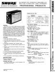
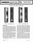
2 8 9 mm
(11-318
IN.)
178 mm ( 7 IN.)
t 5.5
(7/32
Noise:
Phono: measured at Mix bus output, at least 71 dB
below 10 mV input, 20-20 kHz. Measured at M67
output, noise depends upon M67 master gain control.
With M67 master gain at "5%" ( - 20 dB) noise output
of M67 will be -50 dBv maximum.
Outputs:
lmpedance
Line: Less than 1 % THD with
18 dBm, 30 Hz-20 kHz.
+
input
Actual
(Internal)
Mix Bus
M67 Mix Bus
(3.5k load)
or higher
13 kilohms
t 20%
Front-Panel
Headphone Jack
600 ohms or
greater
70 ohms
&lo%
17 dBV
(7 VRMS)
Rear-Panel
Headphone Jack
Low
5 kilohms
k 20%
1.1 kilohms
-c 20%
Same
as
M67
4 ohms max.
-2dBV
(0.8 V;
80 mW)
Output
Control Interaction:
Under 1% dB with any control combination.
lmpedance
Designed for
Use With
Actual
(Internal)
Input
Clipping
Phono
Magnetic
phono
cartridges
25 kilohms*
+350 pF
90 mV
Line Bridging
Less than
10 kilohms
75 kilohms
t10%
Over +16
d BV
(6.3 VRMS)
Line Terminated
600 ohms
600 ohms
?z 10%
Over 18
dBM
(6.3 VRMS)
Monitor Input
(via headphone
plug)
M67 headphone
jack
1000 ohms
t20%
Over 8
dBV
(2.5 VRMS)
Corresponds
to + I 8 dBM
output from
M67
+
+
'NOTE: The input impedance is set for 25k which is the correct load
for a stereo cartridge operating with the L & R channels
parallel (monophonic mode). ~f an input impedance of 47k is
desired, the 47k resistors (R226, R227) across the phono input
jacks may be removed.
Minimum Common Mode Rejection:
80 dB with line input of 10 volts at 100 Hz.
8-ohm Speaker
Output
8 ohms or
greater
-
+
Overload and Shorting Protection:
Shorting the outputs will produce no damage. Overload
of phono inputs up to 3 volts will produce no damage.
Operating Voltage:
27 Vdc nominal supply from either internal supply
comprised of six 9V type 216 batteries or from the
associated M67 or M63 Audio Master. Minimum supply
is 21.5 Vdc; maximum is 35.0 Vdc.
Inputs:
Input
High
(See
"Headphone"
section)
level of
Monitor Channel: measured at &ohm speaker output
with Bohm load. Less than 1.0% THD with output level
of .56 volts to 8 ohms (40 mW) 100 Hz- 15 kHz. Less
than 2% THD with level of .31 volts at 40 Hz.
Output
Clipping
Level
Designed For
Use With
Line: will not add to noise of M67.
Distortion:
Program Channel: (measured at Mix Bus output)
Phono: Less than 1% THD with input level of 35 mV,
30 Hz-20 kHz.
rnm
IN.)
Weight:
Without batteries: 2.38 kg (5 Ib, 4 oz)
With batteries: 2.61 kg (5 Ib, 12 oz)
CONTROLS, CONNECTIONS
AND OPERATION
CONNECTIONS (TO M67, M63 OR SE30)
Stacking hardware is included for mounting the M67
or M63 on top of the M675. See installation instructions for the A68S Stacking Kit provided in the data
sheet covering mixer and circuitry accessories. The
stacking kit is not used with the SE30. The plug on
the "Headphones" output cable at the rear of the
M675 is inserted fully into the M67, M63 or SE30
Headphones jack. The phono-type plug on the "Mix
Bus" cable at the rear of the M675 is inserted into the
Mix Bus jack on the M67 or SE30, or High Level lnput
of the M63. The red and black "30 VDC" wires at the
rear of the M675 should be connected to the 30 Vdc
connecfors on the M67, M63 or SE30. If rack mounting
is desired, the M67 and M675 can each be mounted in
A68R rack mount accessories. The connecting cables
on the M675 are of sufficient length to reach the M67
in this case.
INPUTS
Line:
The four line inputs (professional three-pin female
audio connector+) are located on the rear panel and
designated "Line 1" through "Line 4." Inputs are
balanced (internal transformer, mumetal shielded)
and connections are Pins 2 and 3 "hot," Pin 1
"ground."
Line 3 and Line 4 may be either 600 ohm line
termination or bridging, the choice being made by
the appropriate position of the "Bridge-Terminate"
switches above the Line 3 and Line 4 input connectors. To obtain "Line" operation for the Line 1 and
Line 2 inputs, the corresponding "Line-Phono"
switch above the lnput 1 and lnput 2 controls on the
front panel must be in the "Line" position.
Impedances and operating signal levels are shown
in the "lnput Specifications" Section.
Phono:
The two phono inputs (RCA type phono jack) are
located on the rear panel and designated "Phono 1"
and "Phono 2." To obtain "Phono" operation for the
Phono 1 and Phono 2 inputs, the corresponding
"Line-Phono" switch above the lnput 1 and lnput 2
controls on the front panel, must be in the "Phono"
position.
The nominal "Phono" input impedance is 25 kilohms
resistive, 330 pF capacitive. In order to change the
resistive input to 47 kilohms, remove the 47-kilohm
resistors at "Phono" input terminals (R226, R227).
When phono inputs are not being used, both "LinePhono" switches should be left in "Line" to conserve battery life.
CONTROLS
Individual lnput Gain Controls:
Front panel controls designated "Input 1" through
"lnput 4" are the individual gain controls for correspondingly numbered inputs. Note that the input
connectors are located on the rear panel directly
behind their corresponding control.
The lnput 1 and lnput 2 controls may be used to
control either "Line 1 - Phono 1" or "Line 2- Phono
2" inputs, respectively, depending upon the position
of the "Line-Phono" switch located immediately
above the lnput 1 and lnput 2 controls.
NOTE: The Line-Phono switches above Controls 1
and 2 are intended as SET-UP CONTROLS,
not operating controls. To conserve battery
life, these switches also control supply voltage to the phono preamplifiers. Hence, the
Line-Phono switches should not be thrown
while "on the air" unless the input controls
are both fully CCW ("0") to avoid introducing switching noise in the program material.
If phono inputs are not being used, both of
these switches should be switched to "Line"
to conserve battery life.
Monitor Gain Control:
This control is used to adjust the level of the front
panel monitor speaker, the front panel Headphone
jack, and the rear panel speaker jack. (See Cue
Operation below.)
tDesigned to mate with Cannon
series or equivalent connector.
XL
series,
Switchcraft
A3
(Q.G.)
OUTPUTS
Mix Bus:
The Mix Bus output is a shielded cable extending
from the rear of the M675 cabinet and terminated
with a phono plug. This cable should be connected
to the "Mix Bus" jack on the back of the M67 or
SE30 (use the "Aux Level Input" on the M63). Once
this connection is made, the four M675 input signals
will be added and mixed with the M67, M63 or
SE30 input signals.
Front Panel Headphone Jack:
This jack provides both program and cue material to
600-ohm headphones. The "Monitor" control on the
front panel is used to adjust this headphone level.
The internal (or external) 8-ohm speaker is muted
when a plug is inserted into this jack.
Rear Panel 600 Ohm Headphone Jack:
This is a two-position jack for monitoring the output
of the M67, when the "Headphone" cable at rear of
M675 chassis is connected to the M67 "Headphone"
jack. The two-position phone jack is used to provide
a choice of level. Normally, a single circuit plug
should be used. If inserted only partially to the first
detent, the output level will be less than when
pushed fully in. If stereo phones are used, the twoposition plug may be inserted fully and the output
will appear in both phones.
This jack is an extension of the two-level headphone
jack of the M67, and hence, it carries program
material only and its level is not controlled by the
monitor level control on the front panel.
While intended primarily for 600-ohm to 2-kilohm
headphones, this jack may be used with 8-ohm to
50-kilohm headphones, with resultant variation in
level. Crystal phones may also be used.
The "Tip" connections of the headphone plugs and
the two phono inputs are in phase with Pin 3 of all
input connectors on both the M675 and M67, and
with the tip of the Mix Bus connector.
Rear Panel 8-Ohm Output Speaker Jack:
This jack is for an 8-ohm high efficiency speaker or
for 8-ohm high quality headphones and provides
both program and cue material. The internal speaker
on the front panel is muted when the phone plug is
inserted into this jack. Use of the front panel
headphone jack, in turn, will mute the internal (or
external) speaker. A mono (2 circuit) plug should
normally be used. If a stereo (3 circuit) plug is used,
external muting of the internal speaker is possible.
See schematic.
Monitor Speaker:
The internal speaker is activated unless either the
external &ohm Output Jack or the front-panel 600ohm Headphone Jack is used. It monitors both
program and cue material.
OPERATION
Cue Operation:
The M675 "lnput" controls are in the Cue position
when rotated fully counter-clockwise and past the
detent.
With no M675 lnput Controls in the "Cue" position,
the monitor amplifier receives a program feed via
the connection to the M67 headphone output. The
an acceptable ac line voltage, due to the characteristics of the M63 power supply. Automatic power
switchover is possible with the SE30, although the
SE30 has its own built-in battery supply for this
purpose.
"Monitor" gain control can then be used to adjust
the level of this signal which appears across the
front panel monitor speaker, the front panel Headphone jack, and the rear panel speaker jack.
When one or more M675 lnput controls are turned to
"Cue" (fully counter-clockwise), the program feed to
the monitor amplifier is attenuated by 19 to 31 dB.
The Cue material is then routed to the monitor
amplifier, overriding the program material. When all
lnput controls are returned to normal (not in cue),
program feed is again applied at normal level to the
monitor amplifier. This provision allows monitoring
of program material at a low level while simultaneously cuing.
Talkback Operation:
To hear talkback material originating at the opposite
end of a two-way line connected to the M67 line
output, turn all input pots on the M675 out of cue
and turn up the monitor amp volume control. The
M67 master volume control may be turned down if
necessary.
DC Power
The M675 can be powered in two ways: by an external source or by internal batteries. When 30 Vdc
is applied to the "30 VDC" connectors of the M675,
the M675 will be turned on. The power "On-Off"
switch on the front panel controls only its own
internal battery supply. Thus, if the M675 is to be
powered by an external source such as an M67,
M63 or SE30, the power switch on the M675 need
not be on. Note that if the M675 internal battery
supply is used to power an accessory such as the
A68M Microphone Preamplifier, the power switch
will control power to the accessory.
The M675 internal battery supply can be used to
provide automatic switchover to battery operation
when used with the M67. When the M675 batteries
are installed and the M675 is connected to an
ac-operated M67, automatic power switchover will
take place if the ac line voltage fails, as long as
the M675 power switch is in the "On" position. The
M675 batteries will then power both the M675 and
the M67. Note that automatic power switchover is
not advisable with the M63, because some battery
drain will occur even when the M63 is operating on
Batteries (not included):
The M675 contains a battery supply requiring six
9V transistor radio batteries (Burgess 2U6, Eveready
#216 or equivalent are recommended). Access to
the steel, leak-resistant battery compartment is on
the bottom panel of the M675. To remove the battery
compartment, each of the two locking screws should
be given a '/4 turn CCW. The battery assembly may
then be removed. The six 9V batteries are snapped
into position on the printed circuit board contained
in the compartment cover. The entire compartment is
removable from the M675 by disconnecting the snap
connector (attached to the leads leaving the cover)
from the M675 receptacle. When the M675 is stacked
with an M67 Mixer, the M675 should be below the
M67 to retain access to this compartment.
Battery Check:
The nominal voltage available from the complement
of six 9V batteries is 27.0 volts. Initially, new batteries may provide a supply voltage of up to 30.5
volts. Minimum acceptable battery voltage is considered to be 21.5 volts.
The battery-check function of the M67 may be used
to indicate battery condition when the M67 and
M675 are used together. "0" on the M67 VU meter
indicates a marginal battery condition.
For best performance on battery operation at
temperatures below 40°F, change batteries when the
1.0 VU or lower.
Battery Check meter reading is
This is due to the operating characteristics of carbon
zinc batteries at low temperatures.
NOTE: For improved performance and longer operation at low temperatures (O0C-32"For lower), use manganese-alkaline batteries
(Mallory MN-1604 or equivalent).
+
RF Susceptibility:
When using M675-M67 combination in a high RF
location, RF pickup may occur due to the grounding system of the Mix Bus on early M67s. If this
difficulty should occur, it may be easily remedied by
Current Drain and Battery Life:
Condition
M675 only, "Phono-Line" in "Line," monitor level down
M675 only, "Phono-Line" in "Phono," monitor level down
M675
M67, "Phono-Line" in "Line," M67 @ + 4 dBM
M67, "Phono-Line" in "Phono," M67 @ + 4 dBM
M675
M675
M67, "Phono-Line" in "Line," M67 @ 4-4 dBM,
M675 monitor speaker at 10 mW
M67, "Phono-Line" in "Phono," M67 @ + 4 dBM,
M675
M675 monitor speaker at 10 mW
+
+
+
+
Approximate
Current Drain
1
4
5
8
mA
mA
mA
mA
Approximate
Battery Life
over 300 hrs
170 hrs
140 hrs
85 hrs
7 mA
100 hrs
10 mA
65 hrs
NOTE: Due to operating characteristics of carbon-zinc batteries at low temperatures, the useful operating
life will be noticeably shorter at lower than normal room temperatures. See Battery Check Instructions.
shorting the ground connection of the M67 Mix Bus
input jack to chassis. To make this modification,
which should be performed by qualified service
personnel only, disconnect ac power from the M67
and remove M67 cover. Connect a short wire from
the ground lug of the Mix Bus jack to the nearest
chassis point. The ground lug of mic. input connector # 2 or #3 may be used. The ground lug is
the large lug closest to the cover. This wire should
be as short as possible.
Conversion of Phono lnputs to Tape (NAB) or Flat:
Inputs 1 and 2 may be converted from RlAA
equalization to tape (7% i.p.s. NAB) or flat. The
modification should be performed by qualified service personnel only.
1. Disconnect M675 from M67.
2. Remove four Phillips Head Screws retaining
cover-one on front, one on back, two on
bottom.
3. Remove cover.
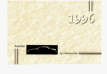
4. Refer to Figure of Printed Circuit Assembly B I .
Note the jumpers on the printed circuit assembly.
5. Remove jumpers from Pin C to Pin E (Channel 1)
and Pin S to Pin V (Channel 2).
6. Replace jumpers to achieve desired equalization.
For Channel 1, jumper C to D for "flat," or B to
D for "tape." For Channel 2, jumper S to T for
"flat" or R to T for "tape."
7. DO NOT remove any jumpers inserted through
the actual printed circuit board. Only change
jumpers between pins mentioned above.
8. Replace cover.
Specifications for Tape and Flat Equalization:
Gain in flat = 6.5 dB to Mix Bus output, Gain in Tape
(7% i.p.s.) = 16.0 dB to Mix BUS output.
Response in flat is i 2 dB, 30-20 kHz.
Response in tape is 2 2 dB of the 71/2 i.p.s. NAB
curve from 50 Hz to 15 kHz.
Distortion: under 1.0% with tape input of 26 mV or
flat input of 78 mV.
lnput Clipping Level: Tape: 80 mV; Flat: 225 mV.
Conversion of Cue Circuitry:
If it is desired that the cuing action (reduction of
program level during cuing) be more pronounced
than the 19 dB-31 dB obtained in a standard M675,
the following modification may be performed by
qualified service personnel only: Remove R115 (470k)
and change R112 (330k) to 2.2 megohms. Program
level reduction during cuing will now be 37 to 49 dB.
Adding Microphone Inputs:
The M675 line inputs may be adapted for use with
microphone inputs by the addition of one or two
Shure A68M Microphone Preamplifiers. Remove the
phono pin output connector on the A68M and attach
a professional three-pin male audio connector? in
its place ("hot" lead to pin 3; shield to pins 1 and
2). Connect the A68M to Line lnput 3 or 4 of the
M675. Place the corresponding BridgeITerminate
switch in the Bridge position. Connect the (+) and
( - ) power cables of the A68M to the M675. Note
that the M675 power switch must be turned off to
conserve batteries when the A68M is not in use.
?Designed to mate with Cannon
series or equivalent connector.
XL
series,
Switchcraft
A3
(Q.G.)
DESCRIPTION OF CIRCUITRY
(Refer to Schematic)
lnput Circuitry:
Line inputs 1 and 2 are transformer coupled to
Line/Phono switches 1 and 2. Phono inputs are
amplified by the two phono preamplifiers consisting
of Q1 and Q3 for channel I and Q2 and Q4 for
channel 2. In the phono preamps, equalization is
provided in the feedback path from the collector of
Q3 (Q4) to the emitter of Q1 (Q2). For channel 1
phono equalization, gain is determined by the ratio
of the R7-C6, R9-C10 combination versus R13. The
outputs of the phono preamps also drive the Line/
Phono switches. Setting a Line/Phono switch to
Phono will, in addition to transferring the associated
input volume control, apply dc voltage to the preamplifier power supply terminal. Either switch will
apply power to both phono preamplifiers.
Line inputs 3 and 4 are directly transformer coupled
to input volume controls 3 and 4. Bridge/Terminate
switches on these two inputs switch a 600-ohm terminating resistor off or onto the input of the transformer.
The outputs of the four input pots are summed via
33k build-out resistors and carried via shielded cable
to the Mix Bus input of the associated M67.
Monitor-Cue Circuitry:
The phone plug and cable at rear of the M675 are
plugged into the associated M67 headphone output.
Program material appearing at the M67 output is
brought via this cable to the M675 where it is transformer coupled into emitter-follower Q106. The
output of the follower is applied to FET Q105, which
serves only as a variable attenuator. With no input
pots in cue, the FET is "on" and presents a low
impedance in parallel with R115 (470k). The output
of the FET (Drain) drives the monitor volume control.
When any pots are in cue, their associated 330k
resistor (R218-221) is switched to the cue bus which,
thru R112 (330k) turns the FET off. Hence, the resistance of the FET in shunt with R115 is now very
high, and the program material fed to the monitor
volume pot is reduced in level by 19 to 31 dB. At the
same time, the cue material for the channel in cue is
fed to the cue bus and hence to the top of the
monitor volume control (for channel 1 the path is
R210, C204, C106).
The monitor amplifier is a complementary symmetry
amplifier similar to many hi-fi power amplifiers. The
gain of the stage is 40 dB, determined by the ratio
of R105 to R106. The idle current of the stage is
approximately 1 mA. The output of the monitor amp
drives J7 directly. J7 is transformer coupled to J8
and the internal 2" speaker.
GUARANTEE
This Shure product is guaranteed in normal use to
be free from electrical and mechanical defects for a
period of one year from the date of purchase. Please
retain proof of purchase date. This guarantee includes
all parts and labor.
SHIPPING INSTRUCTIONS
Carefully repack the unit and return it prepaid to
the factory. If outside the United States, return the
unit to your dealer or Authorized Shure Service Center
for repair. The unit will be returned to you prepaid.