1
FMP Programmer’s Guide
DC 900-1339H
Simpact, Inc.
9210 Sky Park Court
San Diego, CA 92123
June 1998
Simpact, Inc.
9210 Sky Park Court
San Diego, CA 92123
(619) 565-1865
FMP Programmer’s Guide
© 1994 through 1998 Simpact, Inc. All rights reserved
Printed in the United States of America
This document can change without notice. Simpact, Inc. accepts no liability for any errors this
document might contain.
Freeway is a registered trademark of Simpact, Inc.
All other trademarks and trade names are the properties of their respective holders.
Cross References:
(keep this hidden)
FMP
fmp
Financial Market
Protocols
Contents
List of Figures
7
List of Tables
9
Preface
11
1
17
Introduction
1.1
Product Overview . . . . . . . . . . . . . . . . . . .
1.1.1 Freeway Server . . . . . . . . . . . . . . . . . .
1.1.2 Embedded ICP . . . . . . . . . . . . . . . . . .
1.2 Freeway Client-Server Environment . . . . . . . . .
1.2.1 Establishing Freeway Server Internet Addresses
1.3 Embedded ICP Environment . . . . . . . . . . . . .
1.4 Client Operations . . . . . . . . . . . . . . . . . . .
1.4.1 Defining the DLI and TSI Configuration . . . .
1.4.2 Opening a Session . . . . . . . . . . . . . . . .
1.4.3 Exchanging Data with the Remote Application .
1.4.4 Closing a Session . . . . . . . . . . . . . . . . .
1.5 FMP Overview . . . . . . . . . . . . . . . . . . . . .
1.5.1 Software Description . . . . . . . . . . . . . . .
1.5.2 Hardware Description . . . . . . . . . . . . . .
2
.
.
.
.
.
.
.
.
.
.
.
.
.
.
.
.
.
.
.
.
.
.
.
.
.
.
.
.
.
.
.
.
.
.
.
.
.
.
.
.
.
.
.
.
.
.
.
.
.
.
.
.
.
.
.
.
.
.
.
.
.
.
.
.
.
.
.
.
.
.
.
.
.
.
.
.
.
.
.
.
.
.
.
.
.
.
.
.
.
.
.
.
.
.
.
.
.
.
.
.
.
.
.
.
.
.
.
.
.
.
.
.
.
.
.
.
.
.
.
.
.
.
.
.
.
.
.
.
.
.
.
.
.
.
.
.
.
.
.
.
.
.
.
.
.
.
.
.
.
.
.
.
.
.
FMP Protocol Summary
2.1
Message Formats. . . . . . . . . . . .
2.1.1 Bisynchronous Market Feeds . .
2.1.1.1 BSC 2780 Frame Structure.
2.1.1.2 BSC 3780 Frame Structure.
DC 900-1339H
17
17
19
21
22
22
22
22
23
23
23
23
24
25
27
.
.
.
.
.
.
.
.
.
.
.
.
.
.
.
.
.
.
.
.
.
.
.
.
.
.
.
.
.
.
.
.
.
.
.
.
.
.
.
.
.
.
.
.
.
.
.
.
.
.
.
.
.
.
.
.
.
.
.
.
.
.
.
.
.
.
.
.
.
.
.
.
.
.
.
.
27
28
28
28
3
FMP Programmer’s Guide
2.1.2 Asynchronous Market Feeds . . . . . . .
2.1.2.1 Structured Asynchronous Frame .
2.1.2.2 Unstructured Asynchronous Frame
2.1.3 Isochronous Market Feeds . . . . . . . .
2.1.4 Bonneville Market Feed. . . . . . . . . .
2.1.5 Character Codes. . . . . . . . . . . . . .
2.1.6 Message Transmission . . . . . . . . . .
2.2 FMP Access Modes . . . . . . . . . . . . . . .
3
.
.
.
.
.
.
.
.
.
.
.
.
.
.
.
.
.
.
.
.
.
.
.
.
.
.
.
.
.
.
.
.
.
.
.
.
.
.
.
.
.
.
.
.
.
.
.
.
.
.
.
.
.
.
.
.
.
.
.
.
.
.
.
.
.
.
.
.
.
.
.
.
.
.
.
.
.
.
.
.
.
.
.
.
.
.
.
.
.
.
.
.
.
.
.
.
.
.
.
.
.
.
.
.
.
.
.
.
.
.
.
.
FMP DLI Functions
3.1
Summary of DLI Concepts . . . . . . . . . . . .
3.1.1 Configuration in the Freeway Environment .
3.1.2 Normal versus Raw Operation . . . . . . . .
3.1.3 Blocking versus Non-blocking I/O . . . . . .
3.1.4 Buffer Management . . . . . . . . . . . . . .
3.2 Example FMP Call Sequences . . . . . . . . . . .
3.3 Overview of DLI Functions for FMP . . . . . . .
3.3.1 DLI Optional Arguments . . . . . . . . . . .
3.4 Overview of FMP Requests using dlWrite . . . .
3.4.1 Commands using Raw dlWrite . . . . . . . .
3.4.1.1 Set Translation Table Command . . . .
3.4.1.2 Clear Statistics Command . . . . . . .
3.4.1.3 Set ICP Message Buffer Size Command
3.4.1.4 Configure Link Command . . . . . . .
3.4.1.5 Start Link Command . . . . . . . . . .
3.4.1.6 Stop Link Command . . . . . . . . . .
3.4.2 Information Requests using Raw dlWrite . .
3.4.2.1 Request Buffer Report . . . . . . . . .
3.4.2.2 Request Configuration Report . . . . .
3.4.2.3 Request Statistics Report . . . . . . . .
3.4.2.4 Request Status Report . . . . . . . . .
3.4.2.5 Request Translation Table Report . . .
3.4.2.6 Request Software Version ID . . . . . .
3.4.3 Data Transfer using Raw dlWrite . . . . . . .
3.4.3.1 Send Normal Data . . . . . . . . . . .
3.4.3.2 Send Transparent Data . . . . . . . . .
4
.
.
.
.
.
.
.
.
29
30
30
31
31
31
32
32
35
.
.
.
.
.
.
.
.
.
.
.
.
.
.
.
.
.
.
.
.
.
.
.
.
.
.
.
.
.
.
.
.
.
.
.
.
.
.
.
.
.
.
.
.
.
.
.
.
.
.
.
.
.
.
.
.
.
.
.
.
.
.
.
.
.
.
.
.
.
.
.
.
.
.
.
.
.
.
.
.
.
.
.
.
.
.
.
.
.
.
.
.
.
.
.
.
.
.
.
.
.
.
.
.
.
.
.
.
.
.
.
.
.
.
.
.
.
.
.
.
.
.
.
.
.
.
.
.
.
.
.
.
.
.
.
.
.
.
.
.
.
.
.
.
.
.
.
.
.
.
.
.
.
.
.
.
.
.
.
.
.
.
.
.
.
.
.
.
.
.
.
.
.
.
.
.
.
.
.
.
.
.
.
.
.
.
.
.
.
.
.
.
.
.
.
.
.
.
.
.
.
.
.
.
.
.
.
.
.
.
.
.
.
.
.
.
.
.
.
.
.
.
.
.
.
.
.
.
.
.
.
.
.
.
.
.
.
.
.
.
.
.
.
.
.
.
.
.
.
.
.
.
.
.
.
.
.
.
.
.
.
.
.
.
.
.
.
.
.
.
.
.
.
.
.
.
.
.
.
.
.
.
.
.
.
.
.
.
.
.
.
.
.
.
.
.
.
.
.
.
.
.
.
.
.
.
.
.
.
.
.
.
.
.
.
.
.
.
.
.
.
.
.
.
.
.
.
.
.
.
.
.
.
.
.
.
.
.
36
36
37
38
39
40
42
44
45
47
47
47
48
49
50
51
53
53
54
54
55
56
57
57
58
59
DC 900-1339H
Contents
3.5
4
Overview of FMP Responses using Raw dlRead . . . . . . .
3.5.1 Received Data . . . . . . . . . . . . . . . . . . . . . . .
3.5.2 Error, Confirmation, and Acknowledgment Responses.
3.5.3 Reports in Response to dlWrite Information Requests .
.
.
.
.
.
.
.
.
.
.
.
.
.
.
.
.
.
.
.
.
.
.
.
.
.
.
.
.
FMP Link Configuration Options
4.1
4.2
Data Rate Option (1) . . . . . . . . . . . . . . .
Clock Source Option (2) . . . . . . . . . . . . .
4.2.1 External . . . . . . . . . . . . . . . . . . . .
4.2.2 Internal . . . . . . . . . . . . . . . . . . . .
4.3 Number of Leading SYN Characters Option (4).
4.4 Protocol Option (5) . . . . . . . . . . . . . . . .
4.5 Parity Option (6) . . . . . . . . . . . . . . . . .
4.6 Character Set Option (7) . . . . . . . . . . . . .
4.6.1 ASCII/LRC-8 . . . . . . . . . . . . . . . . .
4.6.2 EBCDIC/CRC-16 . . . . . . . . . . . . . . .
4.6.3 ASCII/CRC-16 . . . . . . . . . . . . . . . .
4.6.4 ASCII/LRC-8 OR’d with 0x40 Hex . . . . .
4.6.5 EBCDIC/CCITT-0 . . . . . . . . . . . . . .
4.6.6 ASCII/CCITT-0. . . . . . . . . . . . . . . .
4.7 Transmission Block Size Option (8) . . . . . . .
4.8 Data Translation Option (10) . . . . . . . . . . .
4.9 Data Packing Option (12). . . . . . . . . . . . .
4.9.1 How Data Packing Works . . . . . . . . . .
4.9.2 Data Packing Examples. . . . . . . . . . . .
4.10 Buffer Timer Option (15) . . . . . . . . . . . . .
4.11 Modem Control Option (16) . . . . . . . . . . .
4.11.1 RTS Signal . . . . . . . . . . . . . . . . . .
4.11.2 DSR and DCD Signals . . . . . . . . . . . .
4.12 Feed ID Option (18). . . . . . . . . . . . . . . .
4.13 Message Blocking Option (19) . . . . . . . . . .
4.13.1 Raw Blocks . . . . . . . . . . . . . . . . . .
4.13.2 Data Records . . . . . . . . . . . . . . . . .
4.13.3 Single Records . . . . . . . . . . . . . . . .
4.13.4 Data Records with Header . . . . . . . . . .
4.13.5 Raw Blocks with Header . . . . . . . . . . .
DC 900-1339H
60
60
63
63
65
.
.
.
.
.
.
.
.
.
.
.
.
.
.
.
.
.
.
.
.
.
.
.
.
.
.
.
.
.
.
.
.
.
.
.
.
.
.
.
.
.
.
.
.
.
.
.
.
.
.
.
.
.
.
.
.
.
.
.
.
.
.
.
.
.
.
.
.
.
.
.
.
.
.
.
.
.
.
.
.
.
.
.
.
.
.
.
.
.
.
.
.
.
.
.
.
.
.
.
.
.
.
.
.
.
.
.
.
.
.
.
.
.
.
.
.
.
.
.
.
.
.
.
.
.
.
.
.
.
.
.
.
.
.
.
.
.
.
.
.
.
.
.
.
.
.
.
.
.
.
.
.
.
.
.
.
.
.
.
.
.
.
.
.
.
.
.
.
.
.
.
.
.
.
.
.
.
.
.
.
.
.
.
.
.
.
.
.
.
.
.
.
.
.
.
.
.
.
.
.
.
.
.
.
.
.
.
.
.
.
.
.
.
.
.
.
.
.
.
.
.
.
.
.
.
.
.
.
.
.
.
.
.
.
.
.
.
.
.
.
.
.
.
.
.
.
.
.
.
.
.
.
.
.
.
.
.
.
.
.
.
.
.
.
.
.
.
.
.
.
.
.
.
.
.
.
.
.
.
.
.
.
.
.
.
.
.
.
.
.
.
.
.
.
.
.
.
.
.
.
.
.
.
.
.
.
.
.
.
.
.
.
.
.
.
.
.
.
.
.
.
.
.
.
.
.
.
.
.
.
.
.
.
.
.
.
.
.
.
.
.
.
.
.
.
.
.
.
.
.
.
.
.
.
.
.
.
.
.
.
.
.
.
.
.
.
.
.
.
.
.
.
.
.
.
.
.
.
.
.
.
.
.
.
.
.
.
.
.
.
68
69
69
70
70
70
71
71
71
72
72
72
72
72
72
73
74
75
76
79
80
80
81
81
81
83
84
86
87
88
5
FMP Programmer’s Guide
4.13.6 Message Blocking for the Bonneville Feed . . . . . .
4.14 Block Checking Option (20). . . . . . . . . . . . . . . .
4.15 Queue Limit Option (21) . . . . . . . . . . . . . . . . .
4.16 ETB Switch Option (24) . . . . . . . . . . . . . . . . . .
4.17 DSR Delay Option (30) . . . . . . . . . . . . . . . . . .
4.18 Line Mode Option (33) . . . . . . . . . . . . . . . . . .
4.19 Asynchronous Terminating Character Option (34) . . .
4.20 Number of Terminating Characters Option (38). . . . .
4.21 User-defined Data Rate Option (39) . . . . . . . . . . .
4.21.1 Example for Platforms other than the Freeway 1000
4.21.2 Example for the Freeway 1000 Platform . . . . . . .
4.22 Electrical Interface Option (40) . . . . . . . . . . . . . .
5
.
.
.
.
.
.
.
.
.
.
.
.
.
.
.
.
.
.
.
.
.
.
.
.
.
.
.
.
.
.
.
.
.
.
.
.
.
.
.
.
.
.
.
.
.
.
.
.
.
.
.
.
.
.
.
.
.
.
.
.
.
.
.
.
.
.
.
.
.
.
.
.
.
.
.
.
.
.
.
.
.
.
.
.
.
.
.
.
.
.
.
.
.
.
.
.
FMP Link Configuration Using dlicfg
5.1
5.2
A
.
.
.
.
.
.
.
.
.
.
.
.
97
Configuration Overview . . . . . . . . . . . . . . . . . . . . . . . . . . . 97
DLI Session Configuration . . . . . . . . . . . . . . . . . . . . . . . . . 102
Line Control Procedures
A.1
A.2
A.3
A.4
A.5
89
90
91
92
92
92
93
93
93
94
95
95
DSR Up/Down Reporting
Freeway/Line Interface . .
Modem Control Lines . .
Clock Signals . . . . . . .
Idle Line Condition . . .
105
.
.
.
.
.
.
.
.
.
.
.
.
.
.
.
.
.
.
.
.
.
.
.
.
.
.
.
.
.
.
.
.
.
.
.
.
.
.
.
.
.
.
.
.
.
.
.
.
.
.
.
.
.
.
.
.
.
.
.
.
.
.
.
.
.
.
.
.
.
.
.
.
.
.
.
.
.
.
.
.
.
.
.
.
.
.
.
.
.
.
.
.
.
.
.
.
.
.
.
.
.
.
.
.
.
.
.
.
.
.
.
.
.
.
.
.
.
.
.
.
.
.
.
.
.
.
.
.
.
.
105
105
106
106
107
B
ASCII Translation Tables
109
C
Error Codes
117
D
FMP Loopback Test Program
121
D.1 Loopback Test Programs. . . . . . . . . . . . . . . . . . . . . . . . . . . 121
Index
6
127
DC 900-1339H
List of Figures
Figure 1–1:
Freeway Configuration . . . . . . . . . . . . . . . . . . . . . . . . . . .
18
Figure 1–2:
Embedded ICP Configuration . . . . . . . . . . . . . . . . . . . . . . .
19
Figure 1–3:
A Typical Freeway Server Environment . . . . . . . . . . . . . . . . . .
21
Figure 3–1:
“C” Definition of DLI Optional Arguments Structure . . . . . . . . . .
44
Figure 3–2:
Link Configuration Block with Two Options . . . . . . . . . . . . . . .
50
Figure 3–3:
Packed Data with 5-Byte Header Format . . . . . . . . . . . . . . . . .
62
Figure 4–1:
Data Packing Enabled (Message Blocking = Raw Blocks) . . . . . . . . .
77
Figure 4–2:
Data Packing Enabled (Message Blocking = Data Records) . . . . . . . .
77
Figure 4–3:
Data Packing Enabled (Message Blocking = Single Records) . . . . . . .
78
Figure 4–4:
Data Packing Enabled (Message Blocking = Data Records with Header) .
78
Figure 4–5:
Data Packing Enabled (Message Blocking = Raw Blocks with Header) . .
79
Figure 4–6:
Received Data Used in Message Blocking and Data Packing Examples .
82
Figure 4–7:
Message Blocking Example (Raw Blocks) . . . . . . . . . . . . . . . . .
83
Figure 4–8:
Example of User’s Outbound Message (Raw Blocks Option) . . . . . . .
84
Figure 4–9:
Message Blocking Example (Data Records) . . . . . . . . . . . . . . . .
85
Figure 4–10: User’s Non-transparent Outbound Message (Data Records Option) . . .
85
Figure 4–11: Message Blocking Example (Single Records) . . . . . . . . . . . . . . . .
86
Figure 4–12: Example of a User’s Transparent Inbound Message . . . . . . . . . . . .
87
Figure 4–13: Message Blocking Example (Data Records with Header) . . . . . . . . .
88
Figure 4–14: Message Blocking Example (Raw Blocks with Header) . . . . . . . . . .
89
Figure 5–1:
DLI and TSI Configuration Process . . . . . . . . . . . . . . . . . . . . 101
Figure 5–2:
Example DLI Configuration File for Two Links . . . . . . . . . . . . . . 103
DC 900-1339H
7
FMP Programmer’s Guide
8
DC 900-1339H
List of Tables
Table 2–1:
Messages Duplicated for all Non-Control Sessions on a Link . . . . . . .
33
Table 2–2:
FMP Session Access Modes . . . . . . . . . . . . . . . . . . . . . . . . .
33
Table 2–3:
FMP Access Modes for Various Operations . . . . . . . . . . . . . . . . .
34
Table 3–1:
DLI Call Sequence for FMP (Blocking I/O). . . . . . . . . . . . . . . . .
40
Table 3–2:
DLI Call Sequence for FMP (Non-blocking I/O) . . . . . . . . . . . . . .
41
Table 3–3:
DLI Functions: Syntax and Parameters (Listed in Typical Call Order) . .
43
Table 3–4:
Categories for FMP dlWrite Requests. . . . . . . . . . . . . . . . . . . .
46
Table 3–5:
Buffer Report Definition . . . . . . . . . . . . . . . . . . . . . . . . . . .
53
Table 3–6:
Statistics Report Definition . . . . . . . . . . . . . . . . . . . . . . . . .
54
Table 3–7:
Status Report Definition . . . . . . . . . . . . . . . . . . . . . . . . . . .
55
Table 3–8:
FMP Response Codes . . . . . . . . . . . . . . . . . . . . . . . . . . . .
61
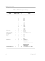
Table 4–1:
FMP Default Options and Settings . . . . . . . . . . . . . . . . . . . . .
66
Table 4–2:
Modem Control Option Settings . . . . . . . . . . . . . . . . . . . . . .
80
Table 4–3:
Message Blocking Option Settings for Received Data . . . . . . . . . . .
82
Table 5–1:
FMP ICP Link Parameters and Defaults for Using dlicfg. . . . . . . . . . 104
Table A–1:
EIA-232 Modem Control Lines . . . . . . . . . . . . . . . . . . . . . . . 106
Table A–2:
EIA-232 Clock Signals . . . . . . . . . . . . . . . . . . . . . . . . . . . . 107
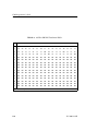
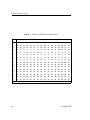
Table B–1:
ASCII to EBCDIC Translation Table 1 . . . . . . . . . . . . . . . . . . . 110
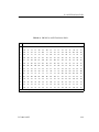
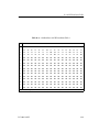
Table B–2:
EBCDIC to ASCII Translation Table 1 . . . . . . . . . . . . . . . . . . . 111
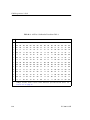
Table B–3:
ASCII to 6-bit Baudot Translation Table 2 . . . . . . . . . . . . . . . . . 112
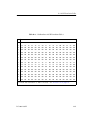
Table B–4:
6-bit Baudot to ASCII Translation Table 2 . . . . . . . . . . . . . . . . . 113
Table B–5:
ASCII to 5-bit Baudot Translation Table 3 . . . . . . . . . . . . . . . . . 114
Table B–6:
5-bit Baudot to ASCII Translation Table 3 . . . . . . . . . . . . . . . . . 115
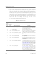
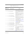
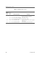
Table C–1:
FMP Error Codes. . . . . . . . . . . . . . . . . . . . . . . . . . . . . . . 118
Table D–1:
Loopback Test Programs and Directories . . . . . . . . . . . . . . . . . . 121
DC 900-1339H
9
FMP Programmer’s Guide
10
DC 900-1339H
Preface
Purpose of Document
This document describes the operation and programming interface required to use
Simpact’s Financial Market Protocols (FMP) product for Simpact’s Freeway communications server or embedded ICP. It is written for subscribers who receive broadcast market feeds from various stock exchanges.
Note
In this document, the term “Freeway” can mean either a Freeway
server or an embedded ICP. For the embedded ICP, also refer to
the user’s guide for your ICP and operating system (for example,
the ICP2432 User’s Guide for Windows NT).
Intended Audience
This document should be read by programmers who are interfacing an application program (such as a ticker plant) to one or more of the primary U.S. or international market
feeds. You should understand the Freeway data link interface (DLI), as explained in the
Freeway Data Link Interface Reference Guide, and be familiar with the message formats
of the market feeds you are receiving.
Required Equipment
The FMP product requires the following two major hardware components to operate:
DC 900-1339H
11
FMP Programmer’s Guide
•
a Freeway communications server or embedded ICP that runs the communications software
•
a client computer that runs the following:
•
TCP/IP (for a Freeway server)
•
Freeway DLI
•
the user application program
Organization of Document
Chapter 1 is an overview of Freeway and the FMP product.
Chapter 2 summarizes the basic communication protocol formats available on the FMP
software package.
Chapter 3 describes how to use the data link interface (DLI) between the client application program and the FMP communications software running on the Freeway ICP.
Chapter 4 describes the link configuration options available on the FMP software package.
Chapter 5 describes how to configure the FMP link options using the dlicfg program.
4/5/99 Leslie:
Add DC-9001512, Solaris
STREAMS
Techpubs:
Don’t delete
the “Other
Helpful
Documents”
(separate
table at end of
References).
Also set “space
below” on first
table = 0 pt.
Appendix A describes the line control procedures for FMP.
Appendix B contains the ASCII/EBCDIC and ASCII/Baudot code translation tables.
Appendix C describes error handling and lists the error codes.
Appendix D describes the FMP loopback test program.
Simpact References
The following documents provide useful supporting information, depending on the
customer’s particular hardware and software environments. Most documents are
available on-line at Simpact’s web site, www.simpact.com.
12
DC 900-1339H
Preface
General Product Overviews
•
•
•
•
Freeway 1100 Technical Overview
Freeway 2000/4000/8800 Technical Overview
ICP2432 Technical Overview
ICP6000X Technical Overview
25-000-0419
25-000-0374
25-000-0420
25-000-0522
Hardware Support
•
•
•
•
•
•
•
•
•
•
Freeway 1100/1150 Hardware Installation Guide
Freeway 1200 Hardware Installation Guide
Freeway 1300 Hardware Installation Guide
Freeway 2000/4000 Hardware Installation Guide
Freeway 8800 Hardware Installation Guide
Freeway ICP6000R/ICP6000X Hardware Description
ICP6000(X)/ICP9000(X) Hardware Description and Theory of
Operation
ICP2424 Hardware Description and Theory of Operation
ICP2432 Hardware Description and Theory of Operation
ICP2432 Hardware Installation Guide
DC 900-1370
DC 900-1537
DC 900-1539
DC 900-1331
DC 900-1553
DC 900-1020
DC 900-0408
DC 900-1328
DC 900-1501
DC 900-1502
Freeway Software Installation Support
•
•
•
•
•
•
•
•
Freeway Release Addendum: Client Platforms
Freeway User’s Guide
Getting Started with Freeway 1100/1150
Getting Started with Freeway 1200
Getting Started with Freeway 1300
Getting Started with Freeway 2000/4000
Getting Started with Freeway 8800
Loopback Test Procedures
DC 900-1555
DC 900-1333
DC 900-1369
DC 900-1536
DC 900-1538
DC 900-1330
DC 900-1552
DC 900-1533
Embedded ICP Installation and Programming Support
•
•
•
•
•
•
ICP2432 User’s Guide for Digital UNIX
ICP2432 User’s Guide for OpenVMS Alpha
ICP2432 User’s Guide for OpenVMS Alpha (DLITE Interface)
ICP2432 User’s Guide for Solaris STREAMS
ICP2432 User’s Guide for Windows NT
ICP2432 User’s Guide for Windows NT (DLITE Interface)
DC 900-1339H
DC 900-1513
DC 900-1511
DC 900-1516
DC 900-1512
DC 900-1510
DC 900-1514
13
FMP Programmer’s Guide
Application Program Interface (API) Programming Support
•
•
•
Freeway Data Link Interface Reference Guide
Freeway Transport Subsystem Interface Reference Guide
QIO/SQIO API Reference Guide
DC 900-1385
DC 900-1386
DC 900-1355
Socket Interface Programming Support
•
Freeway Client-Server Interface Control Document
DC 900-1303
Toolkit Programming Support
•
Freeway Server-Resident Application and Server Toolkit
Programmer’s Guide
OS/Impact Programmer’s Guide
Protocol Software Toolkit Programmer’s Guide
•
•
DC 900-1325
DC 900-1030
DC 900-1338
Protocol Support
•
•
•
•
•
•
•
•
•
•
•
•
•
•
•
•
ADCCP NRM Programmer’s Guide
Asynchronous Wire Service (AWS) Programmer’s Guide
Addendum: Embedded ICP2432 AWS Programmer’s Guide
AUTODIN Programmer’s Guide
Bit-Stream Protocol Programmer’s Guide
BSC Programmer’s Guide
BSCDEMO User’s Guide
BSCTRAN Programmer’s Guide
DDCMP Programmer’s Guide
FMP Programmer’s Guide
Military/Government Protocols Programmer’s Guide
SIO STD-1200A (Rev. 1) Programmer’s Guide
SIO STD-1300 Programmer’s Guide
X.25 Call Service API Guide
X.25/HDLC Configuration Guide
X.25 Low-Level Interface
DC 900-1317
DC 900-1324
DC 900-1557
DC 908-1558
DC 900-1574
DC 900-1340
DC 900-1349
DC 900-1406
DC 900-1343
DC 900-1339
DC 900-1602
DC 908-1359
DC 908-1559
DC 900-1392
DC 900-1345
DC 900-1307
Other helpful documents:
14
•
General Information — Binary Synchronous Communications, GA27-3004
IBM
•
3274 Control Unit Description and Programmer’s Guide, IBM
GA23-0061
DC 900-1339H
Preface
Document Conventions
This document follows the most significant byte first (MSB) and most significant word
first (MSW) conventions for bit-numbering and byte-ordering. In all packet transfers
between the client applications and the ICPs, the ordering of the byte stream is preserved. However, FMP packed data contains word values that are not byte-swapped.
The term “Freeway” refers to any of the Freeway server models (for example, Freeway
1100/1150/1200/1300, Freeway 2000/4000, or Freeway 8800), or to the embedded ICP
product (for example, the embedded ICP2432).
Physical “ports” on the ICPs are logically referred to as “links.” However, since port and
link numbers are usually identical (that is, port 0 is the same as link 0), this document
uses the term “link.”
Program code samples are written in the “C” programming language.
Revision History
The revision history of the FMP Programmer’s Guide, Simpact document
DC 900-1339H, is recorded below:
Document Revision
Release Date
Description
DC 900-1339A
DC 900-1339B
DC 900-1339C
June 1994
October 1994
November 1994
DC 900-1339D
February 1995
DC 900-1339E
January 1996
Preliminary release
Full release
• Minor modifications and updated error codes
• Updated file names for software release 2.1
• Change the usICPStatus field to iICPStatus
and change the usProtModifier field to
iProtModifier (page 44)
• Minor modifications
• Add the Freeway 1000 user-defined data rate
(Section 4.21.2)
• New FMP options in Chapter 4 and Chapter 5.
• Minor modifications
• Add dlControl function (Table 3–3 on page 43)
• Add Windows NT to Chapter 5 and Appendix D
DC 900-1339H
15
FMP Programmer’s Guide
Document Revision
DC 900-1339F
Release Date
April 1997
Description
•
•
•
•
•
DC 900-1339G
August 1997
DC 900-1339H
June 1998
•
•
•
•
•
•
•
•
•
•
Add Simpact browser configuration information
Add normal and transparent data codes to dlRead
responses (Table 3–8 on page 61)
Modify Table 2–1 on page 33, Section 3.4.3 on
page 57, Section 3.5.1 on page 60, Table 5–1 on
page 104, and Table C–1 on page 118
Add Data Packing option (Section 4.9 on page 74)
Modify Message Blocking option (Section 4.13 on
page 81)
Modify the explanation of Figure 3–3 on page 62
Correct message blocking option default
(Table 4–1 on page 66)
Correct ETB enable option default (Table 5–1 on
page 104)
Minor changes in Chapter 5 and Appendix D
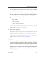
Modify Section 1.1 through Section 1.4
Remove browser interface support
Add the Bonneville Market Feed (Section 2.1.4 on
page 31, Section 4.13.6 on page 89, and
Section 4.14 on page 90)
Minor changes to Section 3.1.2 on page 37 and
Section 3.2 on page 40, add dlpErrString and
dlSyncSelect functions (Table 3–3 on page 43)
Add 5-byte header codes to Table C–1 on page 118
Minor changes to Chapter 5 and Appendix D
Customer Support
If you are having trouble with any Simpact product, call us at 1-800-275-3889 Monday
through Friday between 8 a.m. and 5 p.m. Pacific time.
You can also fax your questions to us at (619)560-2838 or (619)560-2837 any time.
Please include a cover sheet addressed to “Customer Service.”
We are always interested in suggestions for improving our products. You can use the
report form in the back of this manual to send us your recommendations.
16
DC 900-1339H
Chapter
1
Introduction
1.1 Product Overview
Most recent
modification
date:
03/25/98
Leslie: Remove
“Freeway
Embedded”
and just say
“embedded
ICP” (as an
interim fix
prior to BIG
makeover).
Simpact provides a variety of wide-area network (WAN) connectivity solutions for
real-time financial, defense, telecommunications, and process-control applications.
Simpact’s Freeway server offers flexibility and ease of programming using a variety of
LAN-based server hardware platforms. Now a consistent and compatible embedded
intelligent communications processor (ICP) product offers the same functionality as
the Freeway server, allowing individual client computers to connect directly to the
WAN.
Both Freeway and the embedded ICP use the same data link interface (DLI). Therefore,
migration between the two environments simply requires linking your client application with the proper library. Various client operating systems are supported (for example, UNIX, VMS, and Windows NT).
Simpact protocols that run on the ICPs are independent of the client operating system
and the hardware platform (Freeway or embedded ICP).
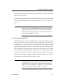
1.1.1 Freeway Server
Simpact’s Freeway communications servers enable client applications on a local-area
network (LAN) to access specialized WANs through the DLI. The Freeway server can be
any of several models (for example, Freeway 1100, Freeway 2000/4000, or Freeway
8000/8800). The Freeway server is user programmable and communicates in real time.
It provides multiple data links and a variety of network services to LAN-based clients.
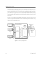
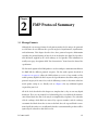
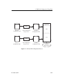
Figure 1–1 shows the Freeway configuration.
DC 900-1339H
17
FMP Programmer’s Guide
To maintain high data throughput, Freeway uses a multi-processor architecture to support the LAN and WAN services. The LAN interface is managed by a single-board computer, called the server processor. It uses the commercially available VxWorks operating
system to provide a full-featured base for the LAN interface and layered services needed
by Freeway.
Freeway can be configured with multiple WAN interface processor boards, each of
which is a Simpact ICP. Each ICP runs the communication protocol software using
Simpact’s real-time operating system.
Application DLI
n
Client n
Server
Processor
SCADA
Defense
ICP
Financial
Commercial
X.25
Bisync
HDLC . . .
ICP
3413
…
Client 2
Ethernet LAN
Application DLI
2
AAAA
AAAA
AA
AAAAAA
AAAA
AA
AAAAAA
AAAA
AA
AAAAAA
AAAA
AA
AAAAAA
Industry Standard Bus
Client 1
WAN Protocol
Options
WAN
Interface
Processors
…
Freeway Server
Application DLI
1
Figure 1–1: Freeway Configuration
18
DC 900-1339H
1: Introduction
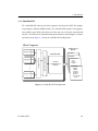
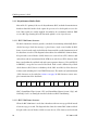
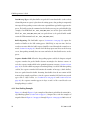
1.1.2 Embedded ICP
The embedded ICP connects your client computer directly to the WAN (for example,
using Simpact’s ICP2432 PCIbus board). The embedded ICP provides client applications with the same WAN connectivity as the Freeway server, using the same data link
interface. The ICP runs the communication protocol software using Simpact’s real-time
operating system. Figure 1–2 shows the embedded ICP configuration.
Client Computer
AAA
AA
AAA
AA
AAAAA
AAAAA
AAA
AA
AAA
AA
AAAAA
AAA
AA
AAAAA
AAA
AA
AAA
Industry Standard Bus
…
Application DLI
2
Simpact Driver
Application DLI
1
WAN Protocol
Options
SCADA
Embedded ICP
Defense
Commercial
X.25
Bisync
HDLC . . .
Simpact
WAN Protocol
Software
Financial
SWIFT
CHIPS
Telerate
Telekurs
Reuters
40+ Market
Feeds . . .
3414
Application DLI
n
Figure 1–2: Embedded ICP Configuration
DC 900-1339H
19
FMP Programmer’s Guide
Summary of product features:
•
Provision of WAN connectivity either through a LAN-based Freeway server or
directly using an embedded ICP
•
Elimination of difficult LAN and WAN programming and systems integration by
providing a powerful and consistent data link interface
•
Variety of off-the-shelf communication protocols available from Simpact which
are independent of the client operating system and hardware platform
•
Support for multiple WAN communication protocols simultaneously
•
Support for multiple ICPs (two, four, eight, or sixteen communication lines per
ICP)
•
Wide selection of electrical interfaces including EIA-232, EIA-449, EIA-485,
EIA-530, EIA-562, V.35, ISO-4903 (V.11), and MIL-188
•
Creation of customized server-resident and ICP-resident software, using
Simpact’s software development toolkits
•
Freeway server standard support for Ethernet and Fast Ethernet LANs running
the transmission control protocol/internet protocol (TCP/IP)
•
Freeway server standard support for FDDI LANs running the transmission control protocol/internet protocol (TCP/IP)
•
Freeway server management and performance monitoring with the simple network management protocol (SNMP), as well as interactive menus available
through a local console, telnet, or rlogin
20
DC 900-1339H
1: Introduction
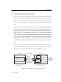
1.2 Freeway Client-Server Environment
The Freeway server acts as a gateway that connects a client on a local-area network to a
wide-area network. Through Freeway, a client application can exchange data with a
remote data link application. Your client application must interact with the Freeway
server and its resident ICPs before exchanging data with the remote data link application.
One of the major Freeway server components is the message multiplexor (MsgMux)
that manages the data traffic between the LAN and the WAN environments. The client
application typically interacts with the Freeway MsgMux through a TCP/IP BSD-style
socket interface (or a shared-memory interface if it is a server-resident application
(SRA)). The ICPs interact with the MsgMux through the DMA and/or shared-memory
interface of the industry-standard bus to exchange WAN data. From the client application’s point of view, these complexities are handled through a simple and consistent
data link interface (DLI), which provides dlOpen, dlWrite, dlRead, and dlClose functions.
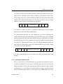
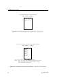
Figure 1–3 shows a typical Freeway connected to a locally attached client by a TCP/IP
network across an Ethernet LAN interface. Running a client application in the Freeway
client-server environment requires the basic steps described in Section 1.4.
Client
Application DLI TSI
TCP/IP
TCP/IP
Socket Interface
client1
192.52.107.99
Freeway
SRA
Msg
TSI Mux
ICP0
ICP1
WAN
Protocols
ICP2
ICP3
3125
Shared Memory
Interface
Ethernet
Industry
Standard Bus
Client
freeway2
192.52.107.100
Figure 1–3: A Typical Freeway Server Environment
DC 900-1339H
21
FMP Programmer’s Guide
1.2.1 Establishing Freeway Server Internet Addresses
The Freeway server must be addressable in order for a client application to communicate with it. In the Figure 1–3 example, the TCP/IP Freeway server name is freeway2,
and its unique Internet address is 192.52.107.100. The client machine where the client
application resides is client1, and its unique Internet address is 192.52.107.99. Refer to
the Freeway User’s Guide to initially set up your Freeway and download the operating
system, server, and protocol software to Freeway.
1.3 Embedded ICP Environment
Refer to the user’s guide for your embedded ICP and operating system (for example, the
ICP2432 User’s Guide for Windows NT) for software installation and setup instructions.
The user’s guide also gives additional information regarding the data link interface
(DLI) and embedded programming interface descriptions for your specific embedded
environment. Refer back to Figure 1–2 on page 19 for a diagram of the embedded ICP
environment. Running a client application in the embedded ICP environment requires
the basic steps described in Section 1.4
1.4 Client Operations
1.4.1 Defining the DLI and TSI Configuration
You must define the DLI sessions and the transport subsystem interface (TSI) connections between your client application and Freeway (or an embedded ICP). To accomplish this, you first define the configuration parameters in DLI and TSI ASCII
configuration files, and then you run two preprocessor programs, dlicfg and tsicfg, to
create binary configuration files (see Chapter 5). The dlInit function uses the binary
configuration files to initialize the DLI environment.
22
DC 900-1339H
1: Introduction
1.4.2 Opening a Session
After the DLI and TSI configurations are properly defined, your client application uses
the dlOpen function to establish a DLI session with an ICP link. As part of the session
establishment process, the DLI establishes a TSI connection with the Freeway MsgMux
through the TCP/IP BSD-style socket interface for the Freeway server, or directly to the
client driver for the embedded ICP environment.
1.4.3 Exchanging Data with the Remote Application
After the link is enabled, the client application can exchange data with the remote application using the dlWrite and dlRead functions.
1.4.4 Closing a Session
When your application finishes exchanging data with the remote application, it calls the
dlClose function to disable the ICP link, close the session with the ICP, and disconnect
from Freeway (or the embedded ICP).
1.5 FMP Overview
Simpact’s Financial Market Protocols (FMP) data feed receiver is a software product
that allows financial analysis programs to receive information from one or more of the
available primary market feeds. Primary market feeds are financial information data
feeds that are digitally broadcast from the world’s stock exchanges. The FMP product
consists of communications software that runs on Simpact’s Freeway platform.
The communications software on Freeway handles the low-level protocol interface
requirements of the market feed, thus freeing clients from this CPU-intensive activity.
The FMP software presents packets of market data to your application program
through the Freeway DLI.
DC 900-1339H
23
FMP Programmer’s Guide
Each serial link on the FMP ICP can be configured as a receiver of one of several defined
market feeds. Each link operates independently of the other links on the same ICP and
can be configured with different communication options.
Data messages on the primary market feeds are broadcast using bisynchronous, asynchronous, or isochronous frames. To receive the bisynchronous information, the Simpact FMP product uses a variation of IBM’s 2780 or 3780 BSC protocol as described in
the document, General Information — Binary Synchronous Communications, IBM. To
receive the asynchronous and isochronous information, the Simpact FMP product uses
various settings of the FMP asynchronous communication capabilities. Refer to
Chapter 4 for more information about the FMP protocol options.
1.5.1 Software Description
Simpact’s FMP product includes the following major software components:
•
A group of communications software downloadable images:
1. Freeway server or embedded ICP software
2. Real-time operating system (OS/Impact)
3. FMP communications software
•
DLI library for linking with client applications
•
A loopback test program (fmpalp.c) to check product installation (see
Appendix D)
•
An interactive demonstration program (bscdemo) that allows a user to send individual commands to the FMP software on Freeway. The bscdemo program is
described in the BSCDEMO User’s Guide.
The Freeway User’s Guide or the user’s guide for your particular embedded ICP and
operating system (for example, the ICP2432 User’s Guide for Windows NT) describes
the software installation procedures. The DLI provides an interface by which data is
24
DC 900-1339H
1: Introduction
exchanged between the client application and Freeway; refer to the Freeway Data Link
Interface Reference Guide.
1.5.2 Hardware Description
A typical Freeway configuration of Simpact’s FMP product requires the following hardware:
•
Communications server processor (for example, Freeway 1100, Freeway 2000,
Freeway 4000 or Freeway 8800) or an embedded ICP (for example, the PCIbus
ICP2432)
•
Ethernet connection to a client running TCP/IP (for a Freeway server)
DC 900-1339H
25
FMP Programmer’s Guide
26
DC 900-1339H
Chapter
2
FMP Protocol Summary
2.1 Message Formats
Although the text message format of each primary market feed is unique, the protocols
used to frame the text fall into three general categories: bisynchronous, asynchronous,
and isochronous. This chapter describes these three protocol categories. Information
regarding the protocol framing of your feed can be found in the digital feed specification document supplied by the stock exchange or feed provider. This information is
usually a one-page description called “line characteristics” located near the front of the
specification.
The line mode option of the FMP product is used to configure communication links on
the FMP ICP for different protocol categories. The line mode option (described in
Section 4.18 on page 92) allows the FMP software to receive a large number of the
world’s primary digital feeds. Refer to your feed specification to determine what general
protocol category it fits into. Next, read the following sections to determine what line
mode option setting to use. Finally, refer to Chapter 4 for any additional options
required for your feed.
All of the feeds described in this chapter are simplex; that is, they are one-way digital
broadcasts. There are no protocol-level acknowledges for received blocks. Retransmission of data blocks for some feeds may be accomplished by telephone. The subscriber
tells the exchange which block was missed (by sequence number) and the exchange
retransmits the block when there is time on the link. Since the repeated block is transmitted to all subscribers, it is usually marked with a retransmission flag so that it will be
ignored by the subscribers who don’t need it.
DC 900-1339H
27
FMP Programmer’s Guide
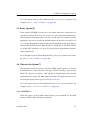
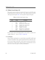
2.1.1 Bisynchronous Market Feeds
Most of the U.S. primary feeds use the bisynchronous (BSC) method of transmission to
broadcast data. BSC market feeds require the presence of a clock signal to receive the
feed. Clock signals are usually supplied externally by the synchronous modem. FMP
receives BSC-type framing when the line mode option is set to bisynchronous.
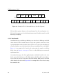
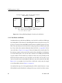
2.1.1.1 BSC 2780 Frame Structure
The BSC 2780 frame structure provides a method of transmitting individually blockchecked messages. Each data message is placed into a single record within the BSC
frame. Several records can be included in the frame until the specified maximum size of
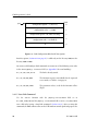
the data frame is reached. The diagram below outlines the normal BSC 2780 text frame.
It begins with a start-of-header (SOH) character or a start-of-text (STX) character and
ends with an end-of-transmission-block (ETB) or an end-of-text (ETX) character. Each
data record within the text block ends with a unit separator character (US in ASCII, IUS
in EBCDIC), except the last record of the block. Each record is followed by a block
check character (BCC) that is a redundancy check (CRC-16 or LRC-8) of the characters
in that record, including the US or ETB/ETX character. The number of synchronization
(SYN) characters are described in Section 4.3 on page 70. PAD characters ensure complete transmission of the data block.
SYN SYN SOH record US BCC record US BCC record ETX BCC PAD
SIAC’s Consolidated Tape System (CTS) and Consolidated Quote System (CQS), and
NASDAQ’s Level 2 are among the market feeds that use BSC 2780 framing.
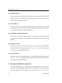
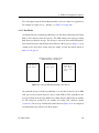
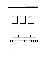
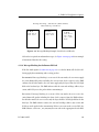
2.1.1.2 BSC 3780 Frame Structure
When the BSC 3780 frame is used, data is broadcast with one message per block instead
of one message per record. The diagram below shows the normal BSC 3780 text block.
It begins with a start-of-header (SOH) or a start-of-text (STX) character and ends with
28
DC 900-1339H
2: FMP Protocol Summary
an end-of-text (ETX) character. Each text block is followed by a block check character
(BCC) that is a redundancy check (CRC-16 or LRC-8) of the characters in the entire
block starting with the first character following SOH or STX and ending with the ETX
character. The number of SYN characters are described in Section 4.3 on page 70. PAD
characters ensure complete transmission of the data block.
SYN SYN SOH
text message
ETX BCC PAD
An example of a market feed that uses normal BSC 3780 framing is the New Market
Reporting System from the Tokyo Stock Exchange.
The diagram below shows the same BSC 3780 message received in transparent BSC
mode. Each block starts with a data-link-escape (DLE) STX character pair (DLE STX
character combination) and ends with a DLE ETX character combination. Data within
the block can appear as any bit combination. Transparency of data is maintained by the
insertion of an additional DLE character after each DLE bit combination within the
data stream. The FMP software removes the additional DLE characters before sending
the message to the client application.
SYN SYN DLE STX
transparent text message
DLE ETX BCC PAD
The Osaka Stock Exchange is one of the market feeds that uses transparent BSC 3780
framing.
2.1.2 Asynchronous Market Feeds
There are two basic types of asynchronous feeds: structured and unstructured. Structured feeds broadcast one text message in each block. Unstructured feeds can consist of
almost any format (or none at all). Asynchronous market feeds do not require external
clock signals to be received. However, the proper data rate option setting must be used
for each asynchronous line whether or not a modem is used. FMP handles these types
DC 900-1339H
29
FMP Programmer’s Guide
of frames when the line mode option is set to one of the asynchronous settings (see
Chapter 4 for more information on these option settings).
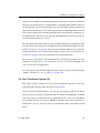
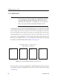
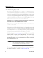
2.1.2.1 Structured Asynchronous Frame
A structured asynchronous frame is similar to a BSC frame containing one message.
The diagram below shows the structured asynchronous text frame which is identical to
a normal BSC 3780 frame without leading SYN or trailing PAD characters. The frame
begins with an STX (or SOH) character and ends with an ETX character. Each text
block is followed by a BCC character (usually LRC-8) that is a redundancy check of the
characters in the entire block starting with the first character following SOH or STX
and ending with the ETX character.
STX
text message
ETX BCC
The London International Financial Futures Exchange (LIFFE) is an example of a market feed using a structured asynchronous frame.
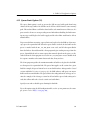
2.1.2.2 Unstructured Asynchronous Frame
The most common method of broadcasting information on an asynchronous line is to
use an unstructured frame. In this format, no start-of-text or end-of-text characters are
broadcast. Characters are received as one continuous stream of information. On some
feeds, a terminating character (TC) can be used to signify the end of a received block as
shown below:
text message
TC
FMP uses the terminating character to divide messages into separate buffers before
sending them to the client. If your feed does not specify a distinct character for message
termination, a common recurring character (such as a carriage return or line feed) can
be used as a message break.
30
DC 900-1339H
2: FMP Protocol Summary
An example of an unstructured asynchronous feed is SIAC’s Ticker A feed.
2.1.3 Isochronous Market Feeds
The isochronous protocol is asynchronous character framing that is clocked by an
external source (such as a modem). FMP receives these feeds in the same manner as the
unstructured asynchronous feeds except that the line mode option must be set to
isochronous and the clock source option must be set to external. See the diagram in
Section 2.1.2.2.
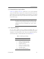
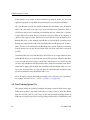
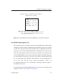
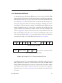
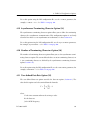
2.1.4 Bonneville Market Feed
The Bonneville feed is an 8-bit asynchronous broadcast feed generated by the
Bonneville Telecommunications Company. Each incoming packet starts with a fixed
size header that contains the count of the data bytes in the packet. The following is an
example of a Bonneville feed packet:
Start Address Byte VCN VCN
Flag
Flag Count High Low
Data Bytes
FCS1
FCS2
End
Flag
The frame check sequence (FCS) for each packet consists of two bytes. The first FCS
byte is calculated by taking the “exclusive or” of every other byte beginning with the
byte count field. The second FCS byte is calculated by taking the “exclusive or” of every
other byte beginning with the VCN high byte. For more information about the
Bonneville packet format, refer to the Packet Definition and Description document
available from the Bonneville Telecommunications Company.
2.1.5 Character Codes
The Simpact FMP software can transmit and receive data in either the American Standard Code for Information Interchange (ASCII) character set, Extended Binary Coded
Decimal Interchange (EBCDIC), or five-level or six-level Baudot code depending on
the setting of the data translation option. The data transferred between the client pro-
DC 900-1339H
31
FMP Programmer’s Guide
gram and the Freeway server or embedded ICP is always in ASCII and is translated by
the FMP software as required.
2.1.6 Message Transmission
In addition to receiving the market feeds, the FMP product can transmit data in the
same format. This capability is not usually used during normal operations; however, it
can be used for port-to-port loopback testing.
The client sends data to the FMP software as a complete message. A message consists of
one buffer of text data. The FMP control characters are not included in the message.
The control characters are inserted by FMP before transmitting the data except when
the message blocking option (Section 4.13 on page 81) is set to no blocking. Once in
memory, FMP may transmit the messages in smaller blocks, called transmission blocks,
to provide more accurate and efficient error control. The FMP software begins each
transmission block with a start-of-header (SOH) control character and ends each message with an end-of-text (ETX) character. All data blocking and deblocking is transparent to the user; however, the ICP message buffer size (Section 3.4.1.3 on page 48) and
transmission block size (Section 4.7 on page 72) must be defined by the user before a
communication link is placed in operation (if other than the default values are
required).
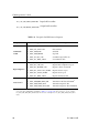
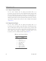
2.2 FMP Access Modes
Each FMP session on a link can be set to one of the following access modes: Manager,
Shared Manager, User, or Control. The access mode is defined in the DLI configuration
file (Chapter 5) using the client-related “mode” parameter (described in the Freeway
Data Link Interface Reference Guide).
When several sessions have access to a link, each non-Control session receives a copy of
any message listed in Table 2–1. A maximum of six non-Control sessions may register
on any one link. Only one Control session is allowed per link.
32
DC 900-1339H
2: FMP Protocol Summary
Table 2–1: Messages Duplicated for all Non-Control Sessions on a Link
Response Codes
DLI_PROT_RECV_PACKED_DATA
Usage
Received packed data
Reference Section
Section 3.5.1 on page 60
DLI_PROT_RECV_PACKED_DATA_EOM Received packed data (EOM) Section 3.5.1 on page 60
DLI_PROT_RESP_ERROR
Error reports
Section 3.5.2 on page 63
DLI_PROT_SEND_NORM_DATA
Received normal data
Section 3.5.1 on page 60
DLI_PROT_SEND_NORM_DATA_EOM
Received normal data (EOM) Section 3.5.1 on page 60
DLI_PROT_SEND_TRANS_DATA
Received transparent data
Section 3.5.1 on page 60
DLI_PROT_SEND_TRANS_DATA_EOM
Received transparent data
(EOM)
Section 3.5.1 on page 60
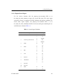
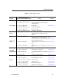
The valid FMP access modes are defined in Table 2–2. Table 2–3 shows the required
access modes for various FMP operations.
Table 2–2: FMP Session Access Modes
Mode
Usage
Manager
Set Manager mode for a session by setting the DLI “mode” configuration
parameter to “mgr.” Manager mode gives the client the right to issue any command or request. There can be only one Manager session per link.
Shared Manager
Shared Manager mode works the same as the Manager mode except that the
exclusive access of Manager mode is not enforced. Set Shared Manager mode
for a session by setting the DLI “mode” configuration parameter to “shrmgr.”
Shared Manager mode gives the client the right to issue any command or
request. There can be up to six Shared Manager sessions per link.
User
Set User mode for a session by setting the DLI “mode” configuration parameter
to “user.” User mode allows clients to receive all messages listed in Table 2–3.
User mode does not allow the client to issue any command that would modify
or change the operational status of the link.
Control
Set Control mode for a session by setting the DLI “mode” configuration parameter to “control.” The Control session may not transmit data and does not
receive incoming data. Any other non-Control sessions for the link with the
active Control session will not receive copies of responses to commands sent by
the Control session. There can be only one Control session per link.
DC 900-1339H
33
FMP Programmer’s Guide
Table 2–3: FMP Access Modes for Various Operations
Operation
34
Access Mode Required
Reference Section
Set Translation Table
Manager or Shared Manager
Section 3.4.1.1
Clear Statistics
Manager or Shared Manager
Section 3.4.1.2
Change Buffer Size
Any mode
Section 3.4.1.3
Configure Link
Manager or Shared Manager
Section 3.4.1.4
Start Link
Manager or Shared Manager
Section 3.4.1.5
Stop Link
Manager or Shared Manager
Section 3.4.1.6
Buffer Report
Any mode
Section 3.4.2.1
Configuration Report
Any mode
Section 3.4.2.2
Statistics Report
Any mode
Section 3.4.2.3
Status Report
Any mode
Section 3.4.2.4
Translation Table Report
Any mode
Section 3.4.2.5
Software Version Report
Any mode
Section 3.4.2.6
Data Transmit (dlWrite)
Manager or Shared Manager
Section 3.4
Data Receive (dlRead)
Any mode
Section 3.5
DC 900-1339H
Chapter
3
Note
FMP DLI Functions
In this document, the term “Freeway” can mean either a Freeway
server or an embedded ICP. For the embedded ICP, also refer to
the user’s guide for your ICP and operating system (for example,
the ICP2432 User’s Guide for Windows NT).
This chapter describes how to use the data link interface (DLI) functions to write client
applications interfacing to the Freeway FMP protocol software. You should be familiar
with the concepts described in the Freeway Data Link Interface Reference Guide ; however, some summary information is provided in Section 3.1.
The following might be helpful references while reading this chapter:
•
Section 3.2 compares a typical sequence of DLI function calls using blocking versus non-blocking I/O.
•
Appendix C explains error handling and provides a summary table for FMP error
codes. The Freeway Data Link Interface Reference Guide gives complete DLI error
code descriptions.
•
The Freeway Data Link Interface Reference Guide provides a generic code example
which can guide your application program development, along with the programs described in Appendix D of this manual.
DC 900-1339H
35
FMP Programmer’s Guide
3.1 Summary of DLI Concepts
The DLI presents a consistent, high-level, common interface across multiple clients,
operating systems, and transport services. It implements functions that permit your
application to use data link services to access, configure, establish and terminate sessions, and transfer data across multiple data link protocols. The DLI concepts are
described in detail in the Freeway Data Link Interface Reference Guide. This section
summarizes the basic information.
3.1.1 Configuration in the Freeway Environment
Several items must be configured before a client application can run in the Freeway
environment:
•
Freeway server configuration
•
data link interface (DLI) session configuration
•
transport subsystem interface (TSI) connection configuration
•
protocol-specific ICP link configuration
The Freeway server is normally configured only once, during the installation procedures described in the Freeway User’s Guide. DLI session and TSI connection configurations are defined by specifying parameters in DLI and TSI ASCII configuration files
and then running two preprocessor programs, dlicfg and tsicfg, to create binary configuration files. Refer to Chapter 5 of this document, as well as the Freeway Data Link
Interface Reference Guide and the Freeway Transport Subsystem Interface Reference
Guide.
ICP link configuration can be performed using any of the following methods:
•
The dlOpen function can configure the ICP links during the DLI session establishment process using the default ICP link configuration values provided by the protocol software.
36
DC 900-1339H
3: FMP DLI Functions
•
You can specify ICP link parameters in the DLI ASCII configuration file and then
run the dlicfg preprocessor program (see Chapter 5). The dlOpen function uses
the resulting DLI binary configuration file to perform the link configuration during the DLI session establishment process.
•
You can perform ICP link configuration within the client application (described
in Section 3.4.1.4). This method is useful if you need to change link configuration
without exiting the application.
3.1.2 Normal versus Raw Operation
There are two choices for the protocol DLI configuration parameter:
•
A session is opened for Normal operation if you set protocol to a specific protocol
(for example, “FMP”); then the DLI software configures the ICP links using the
values in the DLI configuration file and transparently handles all headers and I/O.
•
A session is opened for Raw operation if you set protocol to “raw”; then your
application must handle all configuration, headers, and I/O details. Refer to the
Freeway Data Link Interface Reference Guide if you need to use Raw operation.
To read and write using Normal operation, your client application typically interacts
with Freeway only for the purpose of exchanging data with the remote application. The
writeType DLI configuration parameter (Table 5–1 on page 104) specifies the type of
data (normal or transparent).
However, if your client application needs to interact with Freeway to obtain status or
reports, or to provide Freeway with protocol-specific information relating to the data
exchange, Normal and Raw operation can be mixed. The client application session
should be configured for Normal operation (allowing DLI to handle some of the headers), but the write and read requests (Section 3.4 and Section 3.5) can use Raw operation by including the optional arguments structure (Section 3.3) containing the
protocol-specific information.
DC 900-1339H
37
FMP Programmer’s Guide
Note
For most applications, the FMP protocol requires Raw read and
write requests to specify protocol-specific information.
3.1.3 Blocking versus Non-blocking I/O
Note
Earlier Freeway releases used the term “synchronous” for blocking
I/O and “asynchronous” for non-blocking I/O. Some parameter
names reflect the previous terminology.
Non-blocking I/O applications are useful when doing I/O to multiple channels with a
single process where it is not possible to “block” on any one channel waiting for I/O
completion. Blocking I/O applications are useful when it is reasonable to have the calling process wait for I/O completion.
In the Freeway environment, the term blocking I/O indicates that the dlOpen, dlClose,
dlRead and dlWrite functions do not return until the I/O is complete. For non-blocking
I/O, these functions might return after the I/O has been queued at the client, but before
the transfer to Freeway is complete. The client must handle I/O completions at the software interrupt level in the completion handler established by the dlInit or dlOpen
function, or by periodic use of dlPoll to query the I/O completion status.
The asyncIO DLI configuration parameter specifies whether an application session uses
blocking or non-blocking I/O. The alwaysQIO DLI configuration parameter further
qualifies the operation of non-blocking I/O activity. Refer to the Freeway Data Link
Interface Reference Guide for more information.
The effects on different DLI functions, resulting from the choice of blocking or nonblocking I/O, are explained in the Freeway Data Link Interface Reference Guide and
throughout this chapter as they relate to FMP.
38
DC 900-1339H
3: FMP DLI Functions
3.1.4 Buffer Management
Currently the interrelated Freeway, DLI, TSI and ICP buffers default to a size of 1024
bytes.
Caution
DC 900-1339H
If you need to change a buffer size for your application, refer to the
Freeway Data Link Interface Reference Guide for explanations of
the complexities that you must consider.
39
FMP Programmer’s Guide
3.2 Example FMP Call Sequences
Table 3–1 shows the sequence of DLI function calls to send and receive data using
blocking I/O. Table 3–2 is the non-blocking I/O example. The remainder of this chapter
and the Freeway Data Link Interface Reference Guide give further information about
each function call. Section 3.1.3 on page 38 describes blocking and non-blocking I/O.
Note
The example call sequences assume that the cfgLink and enable
DLI configuration parameters are both set to “yes” (the defaults).
This means that dlOpen configures and enables the ICP links.
Figure 5–2 on page 103 shows an example DLI configuration file.
Table 3–1: DLI Call Sequence for FMP (Blocking I/O)
1. Call dlInit to initialize the DLI operating environment.
The first parameter is your DLI binary configuration file name.
2. Call dlOpen for each required session (link) to get a session ID.
3. Call dlBufAlloc for all required input and output buffers.
4. Call dlWrite to send requests and data to Freeway (Section 3.4 on page 45).
5. Call dlRead to receive responses and data from Freeway (Section 3.5 on page 60).
6. Repeat Step 4 and Step 5 until you are finished writing and reading.
7. Call dlBufFree for all buffers allocated in Step 3.
8. Call dlClose for each session ID obtained in Step 2.
9. Call dlTerm to terminate your application’s access to Freeway.
40
DC 900-1339H
3: FMP DLI Functions
Note
When using non-blocking I/O, a dlRead request must always be
queued to avoid loss of data or responses from the ICP (see Step 5
of Table 3–2).
Table 3–2: DLI Call Sequence for FMP (Non-blocking I/O)
1. Call dlInit to initialize the DLI operating environment.
The first parameter is your DLI binary configuration file name.
2. Call dlOpen for each required session (link) to get a session ID.
3. Call dlPoll to confirm the success of each session ID obtained in Step 2.
4. Call dlBufAlloc for all required input and output buffers.
5. Call dlRead to queue the initial read request.
6. Call dlWrite to send requests and data to Freeway (Section 3.4 on page 45).
7. Call dlRead to queue reads to receive responses and data from Freeway (Section 3.5 on
page 60).
8. As I/Os complete and the I/O completion handler is invoked, call dlPoll to confirm the
success of each dlWrite in Step 6 and to accept the data from each dlRead in Step 7.
9. Repeat Step 6 through Step 8 until you are finished writing and reading.
10. Call dlBufFree for all buffers allocated in Step 4.
11. Call dlClose for each session ID obtained in Step 2.
12. Call dlPoll to confirm that each session was closed in Step 11.
13. Call dlTerm to terminate your application’s access to Freeway.
DC 900-1339H
41
FMP Programmer’s Guide
3.3 Overview of DLI Functions for FMP
This section summarizes the DLI functions used in writing a client application. An
overview of using the DLI functions is:
•
Start up communications (dlInit, dlOpen, dlBufAlloc)
•
Send requests and data using dlWrite
•
Receive responses using dlRead
•
For blocking I/O, use dlSyncSelect to query read availability status for multiple
sessions
•
For non-blocking I/O, handle I/O completions at the software interrupt level in
the completion handler established by the dlInit or dlOpen function, or by
periodic use of dlPoll to query the I/O completion status
•
Monitor errors using dlpErrString
•
If necessary, reset and download the protocol software to the ICP using dlControl
•
Shut down communications (dlBufFree, dlClose, dlTerm)
Table 3–3 summarizes the DLI function syntax and parameters, listed in the most likely
calling order. Refer to the Freeway Data Link Interface Reference Guide for details.
Caution
42
When using non-blocking I/O, there must always be at least one
dlRead request queued to avoid loss of data or responses from the
ICP.
DC 900-1339H
3: FMP DLI Functions
Table 3–3: DLI Functions: Syntax and Parameters (Listed in Typical Call Order)
DLI Function
int dlInit
Parameter(s)
(char *cfgFile,
char *pUsrCb,
int (*fUsrIOCH)(char *pUsrCb));
int dlOpena
(char *cSessionName,
int (*fUsrIOCH)
(char *pUsrCB, int iSessionID));
int dlPoll
(int iSessionID,
int iPollType,
char **ppBuf,
int *piBufLen,
char *pStat,
DLI_OPT_ARGS **ppOptArgs);
int dlpErrString (int dlErrNo);
Parameter Usage
DLI binary configuration file name
Optional I/O complete control block
Optional IOCH and parameter
Session name in DLI config file
Optional I/O completion handler
Parameters for IOCH
Session ID from dlOpen
Request type
Poll type dependent buffer
Size of I/O buffer (bytes)
Status or configuration buffer
Optional arguments
DLI error number (global variable
dlerrno)
Minimum buffer size
Session ID from dlOpen
Buffer to receive data
Maximum bytes to be returned
Optional arguments structure
Session ID from dlOpen
Source buffer for write
Number of bytes to write
Write priority (normal or expedite)
Optional arguments structure
Number of session IDs
Packed array of session IDs
Array containing read status for IDs
Buffer to return to pool
Session ID from dlOpen
Mode (normal or force)
char *dlBufAlloc (int iBufLen);
int dlRead
(int iSessionID,
char **ppBuf,
int iBufLen,
DLI_OPT_ARGS *pOptArgs);
int dlWrite
(int iSessionID,
char *pBuf,
int iBufLen,
int iWritePriority,
DLI_OPT_ARGS *pOptArgs);
int dlSyncSelect (int iNbrSessID,
int sessIDArray[],
int readStatArray[]);
char *dlBufFree (char *pBuf);
int dlClose
(int iSessionID,
int iCloseMode);
int dlTerm
(void);
int dlControl
(char *cSessionName,
Session name in DLI config file
int iCommand,
Command (e.g. reset/download)
int (*fUsrIOCH)
Optional I/O completion handler
(char *pUsrCB, int iSessionID)); Parameters for IOCH
a It is critical for the client application to receive the dlOpen completion status before making any other DLI
requests; otherwise, subsequent requests will fail. After the dlOpen completion, however, you do not have to
maintain a one-to-one correspondence between DLI requests and dlRead requests.
DC 900-1339H
43
FMP Programmer’s Guide
3.3.1 DLI Optional Arguments
Section 3.4 and Section 3.5 describe the dlWrite and dlRead functions for an FMP
application. Both functions can use the optional arguments parameter to provide the
protocol-specific information required for Raw operation (Section 3.1.2). The “C” definition of the optional arguments structure is shown in Figure 3–1.
typedef struct
{
unsigned short
unsigned short
}
unsigned short
unsigned short
unsigned short
unsigned short
short
unsigned short
unsigned short
short
unsigned short
unsigned short
unsigned short
unsigned short
unsigned short
DLI_OPT_ARGS;
_DLI_OPT_ARGS
usFWPacketType;
usFWCommand;
usFWStatus;
usICPClientID;
usICPServerID;
usICPCommand;
iICPStatus;
usICPParms[3];
usProtCommand;
iProtModifier;
usProtLinkID;
usProtCircuitID;
usProtSessionID;
usProtSequence;
usProtXParms[2];
/* FW_CONTROL or FW_DATA
*/
/* FW_ICP_WRITE, FW_ICP_WRITE_EXP */
/*
or FW_ICP_READ
*/
/* Required for start/stop cmds */
/* ICP return error code (dlRead) */
/* Required field (dlWrite)
*/
/* Used for translation tables
*/
Figure 3–1: “C” Definition of DLI Optional Arguments Structure
44
DC 900-1339H
3: FMP DLI Functions
3.4 Overview of FMP Requests using dlWrite
For FMP the dlWrite function supports three dlWrite categories: commands, information requests, and data transfer, which are discussed in detail in Section 3.4.1 through
Section 3.4.3. Whether you use blocking or non-blocking I/O, each dlWrite request
must be followed by a dlRead request to receive the command confirmation, information requested, or acknowledgment of the data transfer. Section 3.5 discusses these different responses received using dlRead.
In a typical FMP application, most dlWrite requests use Raw operation; that is, the
optional arguments structure (page 44) is required to specify protocol-specific information.
If your application is limited to interacting with Freeway only to exchange data with the
remote application, you can read and write using Normal operation. The writeType
DLI configuration parameter (Table 5–1 on page 104) specifies the type of data to be
exchanged. If writeType is set to “normal,” normal data with EOM is used
(Section 3.4.3.1); if writeType is set to “transparent,” transparent data with EOM is
used (Section 3.4.3.2).
Caution
Take care not to confuse the terms “Normal operation” and “normal data.” Normal data can be sent using either Normal or Raw
operation.
Table 3–4 shows the FMP DLI request codes for different categories of the dlWrite
function. Each request is explained in the following sections.
In addition to the command-specific error codes listed in the following sections, an
unsuccessful dlWrite function can return one of the following error codes in the dlRead
pOptArgs.iICPStatus field (see Appendix C for error handling):
DC 900-1339H
45
FMP Programmer’s Guide
DLI_ICP_ERR_INBUF_OVERFLOW
Input buffer overflow
DLI_ICP_ERR_OUTBUF_OVERFLOW Output buffer overflow
Table 3–4: Categories for FMP dlWrite Requests
Category
Commands
to ICP
Report Requests
Data Transfer
a
46
DLI Request Code
Usage
DLI_PROT_CFG_LINK
Configure link
DLI_PROT_CLR_STATISTICS
Clear statistics
DLI_PROT_SEND_BIND
Start link
DLI_PROT_SEND_UNBIND
Stop link
DLI_PROT_SET_BUF_SIZE
Set ICP message buffer size
DLI_PROT_SET_TRANS_TABLE
Set translation table
DLI_PROT_GET_BUF_REPORT
Request buffer report
DLI_PROT_GET_LINK_CFG
Request link configuration report
DLI_PROT_GET_SOFTWARE_VER
Request software version ID
DLI_PROT_GET_STATISTICS_REPORT
Request statistics report
DLI_PROT_GET_STATUS_REPORT
Request status report
DLI_PROT_GET_TRANS_TABLE
Request translation table
DLI_PROT_SEND_NORM_DATA
Transmit normal data
DLI_PROT_SEND_NORM_DATA_EOM
Transmit normal data with EOMa
DLI_PROT_SEND_TRANS_DATA
Transmit transparent data
DLI_PROT_SEND_TRANS_DATA_EOM
Transmit transparent data with EOMa
If you use dlWrite without optional arguments, one of the EOM types is used, depending on the
writeType DLI configuration parameter (Table 5–1 on page 104). If writeType is set to “normal,”
DLI_PROT_SEND_NORM_DATA_EOM is used; if it is set to “transparent,” DLI_PROT_SEND_TRANS_DATA_EOM is
used.
DC 900-1339H
3: FMP DLI Functions
3.4.1 Commands using Raw dlWrite
Section 3.4.1.1 through Section 3.4.1.6 explain how to issue specific commands to the
FMP software using the dlWrite function. Call dlRead to receive the command confirmation response (the dlRead pOptArgs.usProtCommand field is set by the DLI).
3.4.1.1 Set Translation Table Command
Use the dlWrite function with the pOptArgs.usProtCommand field set to
DLI_PROT_SET_TRANS_TABLE to set translation table 1 or 2 (translation table 3 cannot be
changed). Use the MSB of the pOptArgs.usProtCircuitID field to specify the translation table to be set (1 or 2). Each link can use any of the three tables for character translation. After Freeway startup, the tables contain the default values shown in
Appendix B. Use the data area of the buffer pointed to by the pBuf parameter to send the
translation table values. The first 256 bytes of data are the conversion values for the
ASCII-to-new character set translation. The next 256 bytes are the conversion values for
the new character set-to-ASCII translation.
An unsuccessful Set Translation Table command can return one of the following error
codes in the dlRead pOptArgs.iICPStatus field (see Appendix C for error handling):
DLI_ICP_ERR_BAD_MODE
The function request is not available for the requested
access mode; see Table 2–2 on page 33.
DLI_ICP_ERR_BAD_PARMS
The parameter value(s) used for the function call are
illegal.
3.4.1.2 Clear Statistics Command
Use the dlWrite function with the pOptArgs.usProtCommand field set to
DLI_PROT_CLR_STATISTICS to clear the link statistics report. The link statistics are
cleared as soon as this command is received. The statistics are automatically cleared
when a Start Link command (Section 3.4.1.5) is issued.
DC 900-1339H
47
FMP Programmer’s Guide
An unsuccessful Clear Statistics command can return the following error code in the
dlRead pOptArgs.iICPStatus field (see Appendix C for error handling):
DLI_ICP_ERR_BAD_MODE
The function request is not available for the requested
access mode; see Table 2–2 on page 33.
3.4.1.3 Set ICP Message Buffer Size Command
The ICP message buffer size applies to all links on the ICP. The DLI sets the ICP message buffer size as part of the configuration process during the dlOpen command. The
default ICP message buffer size of 1024 is used in the following situations:
•
If the buffer size is not changed when the very first dlOpen is issued, immediately
after the FMP software is downloaded (the dlOpen function uses the value specified in the msgBlkSize parameter value, page 104)
•
If you specify an invalid buffer size for the Set ICP Message Buffer Size command
If your application must set the ICP message buffer size itself (see the caution previously mentioned in Section 3.1.4), it must set the cfgLink and enable DLI configuration parameters to “no” (Section 5.2 on page 102) and perform the following
procedure:
First, download the FMP software and send a dlOpen request for one link on the ICP.
Second, send a dlWrite function with the pOptArgs.usProtCommand field set to
DLI_PROT_SET_BUF_SIZE. Set the iBufLen parameter to 2, and set the write buffer to the
maximum data size (in bytes) for any single transfer to or from the ICP. The valid range
is 256 to 8192 bytes and must be less than or equal to the maxBufSize parameter in the
TSI configuration file (the default value is 1024).
An unsuccessful Set ICP Message Buffer Size command can return one of the following
error codes in the dlRead pOptArgs.iICPStatus field (see Appendix C for error handling):
48
DC 900-1339H
3: FMP DLI Functions
DLI_ICP_ERR_BAD_MODE
The function request is not available for the requested
access mode; see Table 2–2 on page 33.
DLI_ICP_ERR_BAD_PARMS
The parameter value(s) used for the function call are
illegal.
DLI_ICP_ERR_LINK_ACTIVE
The link is already started.
3.4.1.4 Configure Link Command
You can define the ICP link configuration by setting parameters in the DLI text configuration file and running the dlicfg preprocessor program as described in Chapter 5;
however, if your application must perform link configuration, set both the cfgLink and
enable DLI configuration parameters to “no” for that link and then perform the config-
uration as follows:
Use the dlWrite function with the pOptArgs.usProtCommand field set to
DLI_PROT_CFG_LINK to set the link configuration options. The buffer pointed to by the
pBuf parameter contains a string of 16-bit words containing link configuration infor-
mation. The string consists of a variable number of two-word configuration
option/value pairs ending with a zero word. The iBufLen field equals the number of
bytes in the configuration string including the zero terminator word. Figure 3–2 gives
an example of the link configuration string.
Each option number corresponds to a software-selectable option of the FMP software.
The configuration value is used to set that option. Table 4–1 on page 66 lists the available options and values for the FMP protocol.
Leslie — 3/97:
This may not
still be true
about the
Electrical
Interface
option???
All valid parameters are set by the ICP. If invalid parameters are requested, the ICP lists
them in the data area of the response, but no error code is returned. Customers who
want to know if all their link parameters were set can check the data area of the
response. This approach enables applications to set hardware-dependent options on
startup without being concerned about receiving an error. For example, the Electrical
DC 900-1339H
49
FMP Programmer’s Guide
pBuf
configuration option = 1 (data rate)
Word
0
configuration value = 9 (9600)
1
configuration option = 20 (block checking)
2
configuration value = 0 (disabled)
3
0
4
iBufLen = 10
Figure 3–2: Link Configuration Block with Two Options
Interface option (Section 4.22 on page 95) is valid only on the Freeway 1000, not the
Freeway 2000 or 4000.
An unsuccessful Configure Link command can return one of the following error codes
in the dlRead pOptArgs.iICPStatus field (see Appendix C for error handling):
DLI_ICP_ERR_LINK_ACTIVE
The link is already started.
DLI_ICP_ERR_BAD_MODE
The function request is not available for the requested
access mode; see Table 2–2 on page 33.
DLI_ICP_ERR_BAD_PARMS
The parameter value(s) used for the function call are
illegal.
3.4.1.5 Start Link Command
Use the dlWrite function with the pOptArgs.usProtCommand field set to
DLI_PROT_SEND_BIND and the pOptArgs.usICPCommand field set to DLI_ICP_CMD_BIND to
start a link after issuing a Stop Link command (Section 3.4.1.6). After receiving this
command, the FMP software turns on the DTR modem control signal and prepares the
50
DC 900-1339H
3: FMP DLI Functions
link to transmit and receive data according to the current configuration settings. After
a link starts, data transmission can begin on the line.
For blocking I/O, a successful Start Link command returns zero, but you must call
dlRead to receive the DLI_PROT_RESP_BIND_ACK response indicating that the FMP soft-
ware has received a data set ready (DSR) signal from the remote end. The link is not
considered started until this signal is received; however, DSR can be ignored by using
certain settings of the modem control option (Section 4.11 on page 80). If you are using
non-blocking I/O, you must also make a dlRead request to read the completion status.
An unsuccessful Start Link command can return one of the following error codes in the
dlRead pOptArgs.iICPStatus field (see Appendix C for error handling):
DLI_ICP_ERR_LINK_ACTIVE
The link is already started.
DLI_ICP_ERR_BAD_MODE
The function request is not available for the requested
access mode; see Table 2–2 on page 33.
The parameter value(s) used for the function call are
DLI_ICP_ERR_BAD_PARMS
illegal.
3.4.1.6 Stop Link Command
Use the dlWrite function with the pOptArgs.usProtCommand field set to
DLI_PROT_SEND_UNBIND
and
the
pOptArgs.usICPCommand
field
set
to
DLI_ICP_CMD_UNBIND to stop a link without ending your session with Freeway. This
command turns off the DTR modem control signal and shuts down the link transmitter
and receiver. A Stop Link command can be sent to a link that is active or already inactive.
A call to dlClose (described in the Freeway Data Link Interface Reference Guide) also
stops the link, but terminates the session as well. This is the normal method to terminate a session at the end of a client application. The Stop Link command is useful for
temporarily stopping the link without terminating the session (for example, to recon-
DC 900-1339H
51
FMP Programmer’s Guide
figure the link using the Link Configuration command). The link is restarted again by
issuing a Start Link command.
For blocking I/O a successful Stop Link command returns zero, but you must call
dlRead to receive the DLI_PROT_RESP_UNBIND_ACK response indicating the link is deacti-
vated. If you are using non-blocking I/O, you must also make a dlRead request to read
the completion status.
An unsuccessful Stop Link command can return one of the following error codes in the
dlRead pOptArgs.iICPStatus field (see Appendix C for error handling):
DLI_ICP_ERR_BAD_MODE
The function request is not available for the requested
access mode; see Table 2–2 on page 33.
DLI_ICP_ERR_BAD_PARMS
The parameter value(s) used for the function call are
illegal.
52
DC 900-1339H
3: FMP DLI Functions
3.4.2 Information Requests using Raw dlWrite
Section 3.4.2.1 through Section 3.4.2.6 explain how to issue specific information
requests to the FMP software using the dlWrite function. You must then make a Raw
dlRead request to receive the report information (the dlRead pOptArgs.usProtCommand
field is set by the DLI to reflect the type of report, and the iBufLen parameter indicates
the size of the message).
Caution
The dlWrite iBufLen parameter must specify a buffer size large
enough for the requested report; otherwise, the dlRead function
truncates the text to the size indicated by the dlWrite iBufLen
parameter.
3.4.2.1 Request Buffer Report
Use the dlWrite function with the pOptArgs.usProtCommand field set to
DLI_PROT_GET_BUF_REPORT to request a buffer report. The dlRead buffer report response
(the pOptArgs.usProtCommand field is set to DLI_PROT_GET_BUF_REPORT by the DLI) consists of 20 words (40 bytes) of buffer information as described in Table 3–5.
Table 3–5: Buffer Report Definition
Word
1
ICP message buffer size
2
Number of free ICP message buffers
3
Total number of ICP message buffers
4
Transmission buffer size
5
Number of free transmission buffers
6
Total number of transmission buffers
7
Total number of links
8–20
DC 900-1339H
Parameter
Reserved for Simpact diagnostics
53
FMP Programmer’s Guide
3.4.2.2 Request Configuration Report
Use the dlWrite function with the pOptArgs.usProtCommand field set to
DLI_PROT_GET_LINK_CFG to request the current configuration option settings for a link.
The dlRead configuration report response (the pOptArgs.usProtCommand field is set to
DLI_PROT_GET_LINK_CFG by the DLI) consists of a sequence of 16-bit word pairs con-
taining the option number in the first word and the option setting in the second. The
report format is identical to that used by the dlWrite Configure Link command
(Section 3.4.1.4).
3.4.2.3 Request Statistics Report
Use the dlWrite function with the pOptArgs.usProtCommand field set to
DLI_PROT_GET_STATISTICS_REPORT to request link statistics. The FMP software main-
tains a set of link statistics. The report consists of 8 words (16 bytes) of statistics. Link
statistics keep track of events specific to a physical link on the ICP. The format of the
dlRead statistics report response (the pOptArgs.usProtCommand field is set to
DLI_PROT_GET_STATISTICS_REPORT by the DLI) is shown in Table 3–6.
Table 3–6: Statistics Report Definition
Word
54
Statistic
1
Block check errors
2
Parity errors
3
Receive overrun errors
4
Queue limit errors
5
Messages sent
6
Messages received
7
Buffer not available
8
Buffer overrun errors
DC 900-1339H
3: FMP DLI Functions
3.4.2.4 Request Status Report
Use the dlWrite function with the pOptArgs.usProtCommand field set to
DLI_PROT_GET_STATUS_REPORT to request the current link status. The status report
returned by dlRead is a snapshot of the link’s hardware and software condition. The
dlRead status report response (the pOptArgs.usProtCommand field is set to
DLI_PROT_GET_STATUS_REPORT by the DLI) is an eleven-word report containing the cur-
rent link status as shown in Table 3–7.
Table 3–7: Status Report Definition
Word
1
2
3
4
5
6
7
8
DC 900-1339H
Description
Link status
Current operation mode
DTR
DCD
RTS
CTS
Receiver
Transmitter
9
Reserved
10
Reserved
11
DSR
Value
Setting
0
off
1
on
2
starting
0
idle
1
DSR off
0
off
1
on
0
off
1
on
0
off
1
on
0
off
1
on
0
off
1
on
0
off
1
on
0
off
1
on
55
FMP Programmer’s Guide
Link status indicates whether the link is on, off, or starting. Starting indicates that a connection command was received, but the link did not start because it did not receive the
data set ready (DSR) signal from the remote station. A line is off until it is started and
the DSR signal has been received from the remote station.
Current operation mode settings indicate whether the line can operate. A line is idle
when data transmission or reception can occur. The setting is DSR off if the DSR signal
is off.
The signals DTR, DSR, DCD, RTS, and CTS are reported on when the link detects them.
The transmitter or receiver is on while the link is actually transmitting or receiving data.
The transmitter is also reported as on if the link is attempting (unsuccessfully) to transmit data on the line. This situation can occur if the transmit clock signal is not present.
3.4.2.5 Request Translation Table Report
Use the dlWrite function with the pOptArgs.usProtCommand field set to
DLI_PROT_GET_TRANS_TABLE to request any of the three translation tables. Use the MSB
of the pOptArgs.usProtCircuitID field to specify the translation table to be read (1, 2,
or 3).
The dlRead translation table report response (the pOptArgs.usProtCommand field is set
to DLI_PROT_GET_TRANS_TABLE by the DLI) has the same format as the dlWrite Set
Translation Table command (Section 3.4.1.1).
An unsuccessful translation table report request can return the following error code in
the dlRead pOptArgs.iICPStatus field (see Appendix C for error handling):
DLI_ICP_ERR_BAD_PARMS
The parameter value(s) used for the function call are
illegal.
56
DC 900-1339H
3: FMP DLI Functions
3.4.2.6 Request Software Version ID
Use the dlWrite function with the pOptArgs.usProtCommand field set to
DLI_PROT_GET_SOFTWARE_VER to request the software version ID. The dlRead software
version
report
response
(the
pOptArgs.usProtCommand
field
is
set
to
DLI_PROT_GET_SOFTWARE_VER by the DLI) is a one-line report such as the following:
@(#) Simpact FMP for Freeway 2000 – V01.15a 16-May-94 OS/Impact Version V1.5
3.4.3 Data Transfer using Raw dlWrite
FMP provides two write types for sending data: Normal Data and Transparent Data.
The FMP software also provides two command variations (EOM and non-EOM) for
each type of write. These variations are meaningful only when receiving data. When
sending data, they both result in sending a block of data which starts with SOH and
ends with ETX (for BSC and Structured Async lines). This block structure is the most
widely used for BSC type feeds (i.e., feeds from SIAC, OPRA, NASDAQ, etc.). If the
transparent data commands are used, the sent block starts with DLE SOH and ends in
DLE ETX. The FMP software has an ETB Switch option (Section 4.16 on page 92) that
allows sent data blocks to end with ETB instead of ETX in limited situations. More write
format options are available using the Message Blocking option (Section 4.13 on
page 81).
Each dlWrite consists of a data buffer containing n bytes of data, where n is a number
from 0 to the maximum data size specified by the Set ICP Message Buffer Size command (Section 3.4.1.3). The ICP response to each dlWrite is a data acknowledge which
is also called a local ack (DLI_PROT_RESP_LOCAL_ACK). The client application program
can process the local acks itself with dlRead or have the DLI process it automatically (see
below). If an application writes a data message that is larger than the configured ICP
message
buffer
size,
Freeway
returns
the
data
message
with
the
DLI_ICP_ERR_BUF_TOO_SMALL error code instead of the data acknowledge (local ack)
response.
DC 900-1339H
57
FMP Programmer’s Guide
If the localAck DLI configuration parameter is set to “no” (see the Freeway Data Link
Interface Reference Guide), the client application must make a dlRead request to receive
the data acknowledge response for each dlWrite data transfer request (the dlRead
pOptArgs.usProtCommand field is set to DLI_PROT_RESP_LOCAL_ACK by the DLI). One
DLI_PROT_RESP_LOCAL_ACK response (with the dlRead pOptArgs.iICPStatus field set to
1, signifying that one block of data was sent) is sent to the client computer after each
data block has been successfully transmitted to the remote computer, and can be treated
by the client program as the remote acknowledgment. Data acknowledgments are also
used to report transmission errors (as a response to a dlRead request as described in
Section 3.5.2). The client application can use the data acknowledge response to monitor
the success or failure of transmitted data messages, or for regulating the number of outbound messages that the FMP software has pending transmission at any one time.
If the DLI localAck configuration parameter is set to “yes” (which is the default), the
data acknowledge response is implied by a successful dlWrite.
An unsuccessful dlWrite data transfer request can return one of the following error
codes in the dlRead pOptArgs.iICPStatus field (see Appendix C for error handling):
DLI_ICP_ERR_LINK_INACTIVE
The link is stopped.
DLI_ICP_ERR_BAD_MODE
The function request is not available for the requested
access mode; see Table 2–2 on page 33.
DLI_ICP_ERR_XMIT_TIMEOUT
The protocol software was unable to transmit the
data. This error occurs when some or all of the
modem signals are not present.
3.4.3.1 Send Normal Data
If your application needs to perform a Raw dlWrite, use the dlWrite function with the
pOptArgs.usProtCommand
field
set
to
DLI_PROT_SEND_NORM_DATA
or
DLI_PROT_SEND_NORM_DATA_EOM to send normal data.
58
DC 900-1339H
3: FMP DLI Functions
To automatically send normal data with EOM, set writeType = “normal” in the DLI
configuration file (Table 5–1 on page 104).
3.4.3.2 Send Transparent Data
If your application needs to perform a Raw dlWrite, use the dlWrite function with the
pOptArgs.usProtCommand
field
set
to
DLI_PROT_SEND_TRANS_DATA
or
DLI_PROT_SEND_TRANS_DATA_EOM to send transparent data. The client can send transpar-
ent data in either ASCII or EBCDIC mode. In either mode, the data is not code-converted. The blocks are transmitted with DLE SOH and terminated with DLE ETX. The
DLE characters are not counted in the block size. FMP performs all the required DLE
insertion and deletion for transparent data streams.
To automatically send transparent data with EOM, set writeType = “transparent” in
the DLI configuration file (Table 5–1 on page 104).
DC 900-1339H
59
FMP Programmer’s Guide
3.5 Overview of FMP Responses using Raw dlRead
Table 3–8 shows the valid FMP codes sent to your application in response to a Raw
dlRead request; the returned dlRead pOptArgs.usProtCommand field indicates the
response code. If the dlRead return value is zero or positive, it indicates the number of
bytes read; if it is less than zero, an error has occurred. FMP error codes that can be
associated with the responses are described in Appendix C.
Note
The use of Normal dlRead requests (that is, without the optional
arguments parameter) is not recommended for FMP since error
reports would be indistinguishable from data received from the
remote application.
The following types of data can be returned from the ICP:
•
Normal, transparent, and packed received data
•
Error and confirmation responses
•
Acknowledgments (if the localAck DLI configuration parameter is set to “no”)
•
Reports in response to dlWrite information requests
3.5.1 Received Data
FMP provides three read types for receiving data: Normal Data, Transparent Data, and
Packed Data. Data blocks received from the serial line are sent to the client with the
dlRead pOptArgs.usProtCommand field set to one of these data types (see Table 3–8).
Note that the word “SEND” is used in some of the receive command types. This is
because the same command code is used to both send and receive these data types.
The FMP software also provides two command variations (EOM and non-EOM) for
each type of read. When a data block ending with ETX is received on the serial line (BSC
and Structured Async lines), the ICP uses the EOM variation of the data type. This is
60
DC 900-1339H
3: FMP DLI Functions
Table 3–8: FMP Response Codes
Category
Received Data
DLI Response Code in
pOptArgs.usProtCommand Field
Normal or transparent data with header
DLI_PROT_RECV_PACKED_DATA_EOM
Normal or transparent data with header
(end of message)
DLI_PROT_SEND_NORM_DATA
Normal data
DLI_PROT_SEND_NORM_DATA_EOM
Normal data (EOM)
DLI_PROT_SEND_TRANS_DATA
Transparent data
DLI_PROT_SEND_TRANS_DATA_EOM
Transparent data (EOM)
DLI_PROT_RESP_ERROR
Error report; the dlRead pOptArgs.
Appendix C
iICPStatus field contains more information.
DLI_PROT_RESP_LOCAL_ACK
Acknowledgment that a transmission Section 3.4.3.1
buffer has been sent (if the pOptArgs. and
iICPStatus field = 1). If it is less than Section 3.4.3.2
zero, an error has occurred.
DLI_PROT_RESP_BIND_ACK
Acknowledgment of Start Link com- Section 3.4.1.5
mand
DLI_PROT_RESP_UNBIND_ACK
Acknowledgment of Stop Link com- Section 3.4.1.6
mand
DLI_PROT_SET_TRANS_TABLE
Set Translation Table confirmation
Section 3.4.1.1
DLI_PROT_CLR_STATISTICS
Clear Statistics confirmation
Section 3.4.1.2
Command
Confirmations DLI_PROT_SET_BUF_SIZE
Reports
Section
DLI_PROT_RECV_PACKED_DATA
Errorsa
Acknowledgments
Usage
Section 3.5.1
Set ICP Message Buffer Size confirma- Section 3.4.1.3
tion
DLI_PROT_CFG_LINK
Configure Link confirmation
Section 3.4.1.4
DLI_PROT_GET_BUF_REPORT
Buffer report
Section 3.4.2.1
DLI_PROT_GET_LINK_CFG
Link configuration report
Section 3.4.2.2
DLI_PROT_GET_STATISTICS_REPORT
Statistics report
Section 3.4.2.3
DLI_PROT_GET_STATUS_REPORT
Link status report
Section 3.4.2.4
DLI_PROT_GET_TRANS_TABLE
Translation table report
Section 3.4.2.5
DLI_PROT_GET_SOFTWARE_VER
Software version ID report
Section 3.4.2.6
a All of the responses, as well as the error report, can return an error code in dlRead pOptArgs.iICPStatus field
DC 900-1339H
61
FMP Programmer’s Guide
the most widely used format for BSC type feeds (i.e., feeds from SIAC, OPRA, NASDAQ, etc.). When a data block ending with ETB is received or if the ICP must split a single block in order to fit the records into a smaller message buffer, the ICP uses the nonEOM variation. For most data feed applications, both variations should be treated as
the same.
If the Message Blocking option (Section 4.13 on page 81) is set to 0, 1, or 2 (Raw Blocks,
Data Records, or Single Records), the ICP uses the Normal Data types. If the ICP receives
a transparent data block on the line, (i.e., a block starting with DLE SOH or DLE STX
and ending with DLE ETB or DLE ETX), the Transparent Data types are used for those
blocks.
If the Message Blocking option is set to 3 or 4 (Data Records with Header or Raw Blocks
with Header), the ICP uses the Packed Data types for all received data blocks, normal or
transparent. The Packed Data type indicates the presence of 5-byte ICP-generated
record or block headers within the data. Each header consists of a 16-bit count, a 16-bit
sequence number, and an 8-bit error code, as shown in Figure 3–3. The 5-byte header
error code values are listed in Appendix C.
COUNT
SEQUENCE NUMBER
ERROR
data
Figure 3–3: Packed Data with 5-Byte Header Format
The two-byte count includes the sequence number, error byte, and the size of the data
in bytes. Depending on the type of data block received, the 5-byte header can occur
multiple times within a single received data buffer. The client application must be able
to search through the received buffer for multiple records or blocks until the byte count
from the dlRead call is reached.
62
DC 900-1339H
3: FMP DLI Functions
Caution
The 16-bit header fields are not byte-swapped by the FMP software. The client application must perform any necessary swapping. Additionally, packed data headers might not start on word
boundaries. The packed data is in most significant byte (MSB) first
order in the data area.
3.5.2 Error, Confirmation, and Acknowledgment Responses
Table 3–8 lists the possible FMP error, confirmation, and acknowledgment response
codes returned in the dlRead pOptArgs.usProtCommand field. All of the responses, as well
as the DLI_PROT_RESP_ERROR error report, can return an error code in the dlRead
pOptArgs.iICPStatus field to indicate failure. Section 3.4.3 on page 57 gives more
information about the data acknowledgment response (DLI_PROT_RESP_LOCAL_ACK).
3.5.3 Reports in Response to dlWrite Information Requests
After issuing a dlWrite information request (Section 3.4.2 on page 53), a dlRead request
must be issued to receive the report information. The reports are listed in Table 3–8 on
page 61.
DC 900-1339H
63
FMP Programmer’s Guide
64
DC 900-1339H
Chapter
4
FMP Link Configuration
Options
This chapter describes the various link configuration options that can be defined using
the DLI configuration file described in Section 5.2 on page 102. Alternatively, the link
options can be set using the dlWrite Configure Link command as described in
Section 3.4.1.4 on page 49.
Table 4–1 lists all the available options in numerical order along with the allowed settings and defaults. The defaults are in effect immediately after the protocol software is
downloaded to the ICP. They remain in effect until you either modify the DLI configuration file and redownload the ICP, or send a dlWrite Configure Link command.
Note
Link configuration options can be set only when the link being
configured is stopped.
Some of the possible error conditions are discussed in the following sections, as they
relate to using each configuration option. Appendix C explains FMP error handling
and gives a list of errors.
DC 900-1339H
65
FMP Programmer’s Guide
Table 4–1: FMP Default Options and Settings
Option
Data Rate
Value
1
0
75 bits/second
1
110
2
135
3
150
4
300
5
600
6
1200
7
2400
8
4800
9
Clock Source
Default
(✓)
Number
2
✓
Setting
9600
10
19200
11
38400
12
56000
0
✓
1
External
Internal
Number of Leading
Sync Characters
4
n
3
n = sync chars (2 ≤ n ≤ 8)
Protocol
5
2
2
FMP
Parity
6
0
1
None
✓
2
Character Set
Transmission Block Size
66
7
8
0
Odd
Even
✓
ASCII/LRC-8
1
EBCDIC/CRC-16
2
ASCII/CRC-16
3
ASCII/LRC-8 OR’d with 0x40 hex
4
EBCDIC/CCITT-0
5
ASCII/CCITT-0
n
512
n = size in bytes (64 ≤ n ≤ 4096)
DC 900-1339H
4: FMP Link Configuration Options
Table 4–1: FMP Default Options and Settings (Cont’d)
Option
Data Translation
Number
Value
10
0
1
Data Packing
12
Default
(✓)
Setting
Disable
✓
Table 1 (default is EBCDIC)
2
Table 2 (default is Baudot level 6)
3
Table 3 (default is Baudot level 5)
0
Disable
1
✓
Enable
0
n = delay in tenths of seconds
(0 ≤ n ≤ 8000)
Buffer Timer
15
n
Modem Control
16
0
1
HDX-1
✓
FDX-1
2
HDX-2
3
FDX-2
4
HDX-3
5
FDX-3
6
HDX-4
7
FDX-4
Feed ID
18
n
0
Message Blocking
19
0
Raw Blocks
1
Data Records
2
3
Block Checking
20
Single Records
✓
Raw Blocks with Header
0
Disable
✓
2
21
0
24
0
✓
DC 900-1339H
30
n
No limit
Buffer limit (0 ≤ n ≤ 4096)
✓
1
DSR Delay
Exclude first byte
Include first byte
n
ETB Switch
Data Records with Header
4
1
Queue Limit
n = 0–999 (defined by user)
Disable
Enable
3
n = delay in seconds (1 ≤ n ≤ 127)
67
FMP Programmer’s Guide
Table 4–1: FMP Default Options and Settings (Cont’d)
Option
Line Mode
Number
Value
Default
(✓)
33
0
✓
Structured Asynchronous
2
8-bit Unstructured Asynchronous
3
7-bit Unstructured Asynchronous
4
6-bit Unstructured Asynchronous
5
5-bit Unstructured Asynchronous
6
8-bit Isochronous
7
Bonneville Asynchronous Feed
34
A
Number of Terminating
Characters
38
0
39
3
40
A = ASCII character code (0–255)
No terminating character
1
✓
One terminating character
(as defined by option 34)
0
✓
Disable
Time Constant (0 ≤ n ≤ 4096)
n
Electrical Interface
(Freeway 1000 only)
Bisynchronous
1
Asynchronous Terminating Characters
User-defined Data Rate
Setting
0
✓
EIA-232
1
EIA-485
2
EIA-530/EIA-449 (balanced, EIA-422)
3
V.35
4
EIA-449 (unbalanced, EIA-423)
5
EIA-562
4.1 Data Rate Option (1)
The data rate can be set by the client for installations where the FMP software must generate the data clocking signal. If external clocking is provided by a modem or modem
eliminator, the configuration of the data rate is not required. However, when transmitting data, the data rate setting is used to calculate the amount of time to wait before
aborting a transmission with the DLI_ICP_ERR_XMIT_TIMEOUT transmit timeout error.
68
DC 900-1339H
4: FMP Link Configuration Options
Therefore, if FMP is being used to transmit data, the data rate should be set to match,
or be slower than, the modem clock rate.
The data rate on a link can be set from 75 through 56,000 bits/second. When using data
rates above 19,200 bits/second, be careful not to overload the communications server
processor. Freeway supports up to16 links per ICP, and the maximum link data rates
are:
•
1 link at 56,000 b/s
•
4–8 links at 19,200 b/s
•
16 links for a 16-port ICP at 9,600 b/s
To set this option using the DLI configuration file, use the dataRate parameter; for
example, dataRate = 9600. See Table 5–1 on page 104.
4.2 Clock Source Option (2)
The clock source option determines the source of the data clock signals for a link. Data
clocking can be provided by the FMP software or received from an external source.
To set this option using the DLI configuration file, use the clockSource parameter; for
example, clockSource = “external”. See Table 5–1 on page 104.
4.2.1 External
Simpact recommends the external clock setting for most communications applications
that involve a cable length greater than 25 feet. With the external setting, the clock generator is disabled, and data clocking must be supplied by an external source such as a
modem or modem eliminator. Receive clocking is input through the receiver timing
signal (EIA-232 pin 17), and transmit clocking is input through the transmitter timing
signal (EIA-232 pin 15). Your Freeway server is factory configured for external clocking
using a hardware jumper.
DC 900-1339H
69
FMP Programmer’s Guide
4.2.2 Internal
When the internal clock setting is used, the clock signal is generated at the rate specified
in the data rate option (Section 4.1). The generated clock signal is used for transmit
clocking and is output on the terminal timing signal (EIA-232 pin 24). Receive clocking
is input through the receiver timing signal (EIA-232 pin 17). The transmitter timing
signal (EIA-232 pin 15) is not used. Your Freeway server is factory configured for
external clocking using a hardware jumper. If you need to set internal clocking, call the
Simpact customer support number given in the Preface.
4.3 Number of Leading SYN Characters Option (4)
This option specifies the number of SYN characters to precede all transmitted data
blocks. Certain links may require more SYN characters to ensure synchronization on
poor-quality lines. The minimum number of leading SYN characters is two; the maximum number is eight. SYN characters are not added to unstructured asynchronous
transmissions.
To set this option using the DLI configuration file, use the numLeadSync parameter; for
example, numLeadSync = 3. See Table 5–1 on page 104.
4.4 Protocol Option (5)
This option indicates the protocol used on the ICP and has only one setting (FMP).
This setting is reported in the configuration report (Section 3.4.2.2 on page 54) which
may be used by client application programs to verify the protocol running on the ICP.
The DLI configuration program (Chapter 5) considers this protocol option to be protocol-independent, but it must be set to “FMP” in order to select the FMP protocol. This
parameter must be set prior to any attempt to assign another FMP configuration option
within a session definition (see Figure 5–2 on page 103); otherwise the DLI configuration program will fail.
70
DC 900-1339H
4: FMP Link Configuration Options
To set this option using the DLI configuration file, use the protocol parameter; for
example, protocol = “FMP”. See Figure 5–1 on page 104.
4.5 Parity Option (6)
When using the ASCII/LRC-8 character set, this option controls the setting of bit 7 of
each character. Parity can be set to odd, even, or none (space parity for bisynchronous).
Any transmission containing a parity error is detected by the receiver hardware, and the
appropriate error recovery is taken by the FMP software. If no parity is selected, bit 7 is
set to zero for all transmitted characters when using bisynchronous line mode. Parity is
automatically disabled when the EBCDIC/CRC-16, ASCII/CRC-16, EBCDIC/CCITT-0
or ASCII/CCITT-0 character set is used. The parity used for bisynchronous transmission is normally odd.
To set this option using the DLI configuration file, use the parity parameter; for example, parity = “odd”. See Table 5–1 on page 104.
4.6 Character Set Option (7)
This option determines the character code for the FMP control sequences used on the
transmission line. It also determines what type of block checking is done on data
blocks. The character set option is valid only for the bisynchronous and structured
asynchronous line modes. The FMP software transmits all control characters on the
line with space parity when no parity is selected (Section 4.5).
To set this option using the DLI configuration file, use the charSet parameter; for
example, charSet = “asciilrc8”. See Table 5–1 on page 104.
4.6.1 ASCII/LRC-8
When this setting is used, the FMP control sequences are transmitted in 7-bit ASCII
format, and LRC-8 block checking is performed.
DC 900-1339H
71
FMP Programmer’s Guide
4.6.2 EBCDIC/CRC-16
When this setting is used, the FMP control sequences are transmitted in 8-bit EBCDIC
format, and the CRC-16 block check polynomial is performed. The parity option is
ignored when using EBCDIC/CRC-16.
4.6.3 ASCII/CRC-16
When this setting is used, the FMP control sequences are transmitted in 7-bit ASCII
(space parity) format, and the CRC-16 block check polynomial is performed. Data parity checking is disabled when using ASCII/CRC-16.
4.6.4 ASCII/LRC-8 OR’d with 0x40 Hex
This setting is used with the Hong Kong Foreign Exchange feed. The FMP control
sequences are transmitted in 7-bit ASCII format with LRC-8 block checking OR’d with
0x40 hex.
4.6.5 EBCDIC/CCITT-0
When this setting is used, the FMP control sequences are transmitted in 8-bit EBCDIC,
and the CCITT-0 block check polynomial (X16 + X12 + X5 +1) is used. The parity option
is ignored when using EBCDIC/CCITT-0.
4.6.6 ASCII/CCITT-0
When this setting is used, the FMP software uses the CCITT-0 block check polynomial
(X16 + X12 + X5 +1) on all input and output ASCII data blocks. The parity option is
ignored when using ASCII/CCITT-0
4.7 Transmission Block Size Option (8)
The transmission block size is selectable from 64 through 4096 bytes. This value controls the size of the data blocks transferred over the data link. The size of the transmission block includes the bisynchronous text control characters as well as the data
72
DC 900-1339H
4: FMP Link Configuration Options
characters. For example, a transmission block size of 512 bytes consists of 510 bytes of
data plus two control characters (SOH and ETX). SYN, DLE, PAD, and BCC characters
are not included in the transmission block size count. The FMP software automatically
inserts all control characters in the blocks sent and removes them from blocks received.
If the remote station sends a transmission block that is larger than the configured size,
the FMP software sends the DLI_ICP_ERR_BUF_OVERFLOW buffer overrun error to the client with all the data that was received.
The size of message buffers from the client is independent of the transmission block
size. The ICP message buffer size is controlled by the Set ICP Message Buffer Size command (Section 3.4.1.3 on page 48). Messages to be transmitted that are greater than the
transmission block size are broken into smaller messages and sent separately. See
Section 2.1.6 on page 32 for more information on transmission blocks.
For messages received on the communication line, the ICP message buffer size is the
maximum size that can be received; otherwise, the DLI_ICP_ERR_BUF_OVERFLOW error
code is sent to the client application.
To set this option using the DLI configuration file, use the transBlkSize parameter; for
example, transBlkSize = 512. See Table 5–1 on page 104.
4.8 Data Translation Option (10)
This option invokes transmit and receive data translation using one of the three
onboard ASCII translation tables described in Appendix B.
When one of the translation tables is selected, data translation is enabled. Data blocks
from the client are treated as ASCII data and are translated into EBCDIC or Baudot
code before they are transmitted on the communication line. Conversely, data blocks
received from the line are treated as EBCDIC or Baudot code and are translated to
ASCII before they are sent to the client. No translation is done on transparent data
blocks.
DC 900-1339H
73
FMP Programmer’s Guide
If this option is set to disable, no data translation is performed. In this case, the client
application program is responsible for performing any necessary data translation.
The 5-bit Baudot-to-ASCII and ASCII-to-Baudot data translation using Translation
Table 3 does not work in the same way as data translation using Translation Table 1.
ASCII values that are to be translated to 5-bit Baudot code are evaluated to see whether
a figure-shift or letter-shift character should be inserted in front of the character. A
character that requires a figure-shift character inserted before it has the high bit of its
Baudot table value set. For example, if ASCII value 33 (hexadecimal) is translated to its
Baudot code equivalent, the value in the translation table would appear as 81 (hexadecimal). The value 81 (hexadecimal) is the Baudot 01 value with the high bit set indicating
that the character is to be preceded by a figure shift. It is the 01 value that is sent out on
the link.
On inbound data, the letter-shift and figure-shift characters are stripped from the data,
and all Baudot characters are translated to their ASCII equivalents. All figure-shift characters are listed in the last 128 bytes, and all letter-shift characters are listed in the first
128 bytes of the Baudot-to-ASCII translation tables. Only data translation using Translation Table 3 employs this method; data translation using Translation Table 1 or 2 uses
one-to-one correspondence. See Appendix B for the translation tables and for an example of data translation using Translation Table 1 or 2.
To set this option using the DLI configuration file, use the dataTranslation parameter;
for example, dataTranslation = “table1”. See Table 5–1 on page 104.
4.9 Data Packing Option (12)
This option controls the packing of multiple incoming records or blocks into a single
buffer. Data packing is especially useful when receiving a burst of small data blocks
from the serial line (such as test messages). In this situation the data packing feature of
FMP conserves buffer space on Freeway by packing as many of these small blocks as will
74
DC 900-1339H
4: FMP Link Configuration Options
fit in one buffer. Data packing also helps move data from Freeway to the client more
efficiently over the Ethernet.
The default for this option is enabled. To disable this option using the DLI configuration
file, use the dataPacking parameter; for example, dataPacking = “no”. See Table 5–1 on
page 104.
Note
Earlier versions of the BSCDEMO interactive program might display this option as “space compression”; however, you can still use
this option to turn data packing on or off. For more information,
refer to the BSCDEMO User’s Guide.
4.9.1 How Data Packing Works
When data packing is enabled, the FMP software starts packing incoming messages
when it detects that the message buffers are not being read by the client fast enough; i.e.,
unread buffers start collecting on the Freeway ICP board. When this happens, the FMP
software attempts to put any newly received data into the previous waiting message
buffer. This happens only if the previous message buffer has enough free space to hold
the new data. If it does, FMP copies the new data into the previous buffer, placing it
behind the data already in the buffer. The data size of the previous buffer is updated to
reflect the number of bytes added to the buffer. Finally, the ICP buffer that contained
the new data is released to the ICP free pool to be reused.
Note
DC 900-1339H
Data packing takes place only when the client cannot read the
incoming data fast enough. If the client application is keeping up
with the flow of incoming data, it might never see a packed data
buffer, even though the data packing option is enabled.
75
FMP Programmer’s Guide
Data Message Types: Only data buffers are packed. If a non-data buffer (such as a data
acknowledgment or report) is placed on the waiting queue, data packing is temporarily
interrupted. Data packing resumes when two sequential data type buffers appear on the
queue. The buffer retains the command code of the first message in a packed buffer. For
example, if an ETB block (DLI_PROT_SEND_NORM_DATA) was on the queue and an ETX
block (DLI_PROT_SEND_NORM_DATA_EOM) was packed into it, the packed buffer would
retain the ETB command code (DLI_PROT_SEND_NORM_DATA).
Buffer Reporting: The link buffer request (Section 3.4.2.1 on page 53) reports the
number of buffers in the ICP waiting queue (HOSTOQ) at any one time. For best
results on an active link, the buffer request should be issued through the control access
mode (Section 2.2 on page 32). Because the ICP always posts two writes to the Freeway
server, data packing normally does not start until after the third buffer arrives on the
queue.
Sequence Number Field: When the data packing option enabled, the Simpact assigned
sequence numbers for packed buffers become meaningless for obvious reasons. As
such, the sequence number field in the optional arguments structure (Section 3.3.1 on
page 44) is used for a different purpose when data packing is enabled. With data packing
enabled, the sequence number field contains the number of messages (whole buffers)
that were packed into this buffer. Incoming data buffers that do not remain in ICP
memory long enough to pack have a 1 in the sequence number field. On Freeway record
types with a 5-byte header, (see Section 4.13.4 on page 87 and Section 4.13.5 on
page 88), the sequence number appears in bytes 4 and 5 of the record header even
though packing is enabled.
4.9.2 Data Packing Examples
Figure 4–1 through Figure 4–5 give examples of how data is packed for the various Message Blocking options (Section 4.13 on page 81). Compare these with the examples of
unpacked data in Figure 4–7 on page 83 through Figure 4–14 on page 89. Both series of
76
DC 900-1339H
4: FMP Link Configuration Options
figures show how the three example data blocks shown in Figure 4–6 on page 82 would
be received for each option setting
Message Blocking = Raw Blocks
Data Packing = Enabled
3263
<soh> A B C
<etx> <bc1>
<soh> D E F
<etx> <bc2>
<soh> G H I
<us> <bc3>
J K L <etx>
<bc4>
Figure 4–1: Data Packing Enabled (Message Blocking = Raw Blocks)
Message Blocking = Data Records
Data Packing = Enabled
B
E
H
K
C <us>
F <us>
I <us>
L
3265
A
D
G
J
Figure 4–2: Data Packing Enabled (Message Blocking = Data Records)
DC 900-1339H
77
FMP Programmer’s Guide
Message Blocking = Single Records
Data Packing = Enabled
3267
A B C D E F
G H I J K L
Figure 4–3: Data Packing Enabled (Message Blocking = Single Records)
Message Blocking = Data Records (With Header)
Data Packing = Enabled
0
0
0
0
3269
06 00
A B C
06 01
D E F
06 02
G H I
06 02
J K L
Note 5-byte header in this example = 06 00 0
Where: 06 = size of record including seq # and error code
00 = Simpact generated sequence number of block
0 = error code for record
Figure 4–4: Data Packing Enabled (Message Blocking = Data Records with Header)
78
DC 900-1339H
4: FMP Link Configuration Options
Message Blocking = Raw Blocks (With Header)
Data Packing = Enabled
0
A B C <etx> <bc1>
0
D E F <etx> <bc2>
0
G H I <us> <bc3>
<etx> <bc4>
3274
09 00
<soh>
09 01
<soh>
14 02
<soh>
J K L
Note 5-byte
Where: 09 =
00 =
0 =
header in this example: 09 00 0
size of block including seq # and error code
Simpact generated sequence number of block
error code for block
Figure 4–5: Data Packing Enabled (Message Blocking = Raw Blocks with Header)
4.10 Buffer Timer Option (15)
This option allows you to control the amount of time the FMP software holds a buffer
containing data while waiting for additional data. The Buffer Timer interval is specified
in tenths of seconds and can range from 0 (infinite delay) to 8000 (800 seconds). This
option prevents you from waiting indefinitely for a terminating character that does not
arrive. This option applies only when line mode is asynchronous or isochronous; that
is, the line mode option is set to a value greater than or equal to 2. If the interval expires,
the current buffer, if it has data, is sent to the client with the error field marked with
DLI_ICP_ERR_NO_TERM_CHAR. All buffers marked with DLI_ICP_ERR_NO_TERM_CHAR are
sent to the client with the dlRead optArgs.usProtCommand
field set to
DLI_PROT_RECV_PACKED_DATA. The asynchronous terminating character option is
described in Section 4.19.
To set this option using the DLI configuration file, use the bufferTimer parameter; for
example, bufferTimer = 0. See Table 5–1 on page 104.
DC 900-1339H
79
FMP Programmer’s Guide
4.11 Modem Control Option (16)
This option determines two things: the operation of the request to send (RTS) output
modem signal and the detection of the data set ready (DSR) and data carrier detect
(DCD) input modem signals. Table 4–2 lists the possible settings for this option.
Table 4–2: Modem Control Option Settings
Value
Setting
Description
0
HDX-1
Half duplex, detect DSR
1
FDX-1
Full duplex, detect DSR
2
HDX-2
Half duplex, ignore DSR and DCD
3
FDX-2
Full duplex, ignore DSR and DCD
4
HDX-3
Half duplex, detect DCD
5
FDX-3
Full duplex, detect DCD
6
HDX-4
Half duplex, detect DSR and DCD
7
FDX-4
Full duplex, detect DSR and DCD
To set this option using the DLI configuration file, use the modemControl parameter; for
example, modemControl = “FDX1”. See Table 5–1 on page 104.
4.11.1 RTS Signal
When the modem control option is set to any half-duplex setting (HDX), the RTS signal
is turned on when FMP is ready to transmit and turned off when transmission is complete. For any full-duplex setting (FDX), the RTS signal is turned on when the link is
started and stays on until the link is stopped. In all cases, transmission does not start
until a clear to send (CTS) signal is received by the FMP software.
80
DC 900-1339H
4: FMP Link Configuration Options
4.11.2 DSR and DCD Signals
Line activity ceases when the signal on the DSR pin is lost. With either the HDX-2 or
FDX-2 setting, the incoming DSR signal is ignored by the FMP software. This setting is
useful when DSR may not be present.
4.12 Feed ID Option (18)
This option lets the application program assign a number to a configuration. For example, if an application program services a given number of multiple links or communications servers, the configuration feed ID is used to determine what market feed that
line is configured for. In other words, the user application assigns unique feed IDs to
every different market feed. The user application can then identify the market feed by
using the feed ID option. This option has no effect on the FMP software.
To set this option using the DLI configuration file, use the feedID parameter; for example, feedID = 0. See Table 5–1 on page 104.
4.13 Message Blocking Option (19)
This option controls the logical blocking and deblocking of data between ICP message
buffers (Section 3.4.1.3 on page 48) and transmission blocks (Section 4.7 on page 72)
during normal link operation. See Section 2.1.6 on page 32 for more information on
message buffers and transmission blocks. This option, in conjunction with the Data
Packing option (Section 4.9 on page 74), determines how received data is formatted in
an FMP buffer. Table 4–3 summarizes the Message Blocking option settings for received
data.
Before determining which setting is best for your application, it is important to know
the difference between a data block and a data record. A data block starts with STX or
SOH and ends with ETB or ETX followed by a BCC (block check character). A block
can contain one or more records. Multiple records within a block are separated by unit
separator (US) or record separator (RS) characters. Data feeds that use US characters to
DC 900-1339H
81
FMP Programmer’s Guide
Table 4–3: Message Blocking Option Settings for Received Data
Value
Setting
Description
Freeway Data Codes
0
Raw Blocks
Block is received with SOH, US, DLI_PROT_SEND_NORM_DATA
and BCC characters left in
DLI_PROT_SEND_NORM_DATA_EOM
DLI_PROT_SEND_TRANS_DATA
DLI_PROT_SEND_TRANS_DATA_EOM
1
Data Records
BSC control chars are removed, DLI_PROT_SEND_NORM_DATA
US chars are left in to separate DLI_PROT_SEND_NORM_DATA_EOM
records
DLI_PROT_SEND_TRANS_DATA
DLI_PROT_SEND_TRANS_DATA_EOM
2
Single Records
All control chars are removed,
one record per message buffer
3
Data Records
with Header
All control chars are removed
DLI_PROT_RECV_PACKED_DATA
and a 5-byte header before each DLI_PROT_RECV_PACKED_DATA_EOM
record
4
Raw Blocks
with Header
Same as ‘0’ but with a 5-byte
header before each block
DLI_PROT_SEND_NORM_DATA
DLI_PROT_SEND_NORM_DATA_EOM
DLI_PROT_SEND_TRANS_DATA
DLI_PROT_SEND_TRANS_DATA_EOM
DLI_PROT_RECV_PACKED_DATA
DLI_PROT_RECV_PACKED_DATA_EOM
separate records also place a BCC for that record after each US character as well as after
the ETB or ETX.
To illustrate the effects of the Message Blocking option on received data, Figure 4–7 on
page 83 through Figure 4–14 on page 89 graphically represent how the data looks when
received with each of the Message Blocking option settings (when the Data Packing
option is disabled). Compare these with the examples of Data Packing enabled in
Figure 4–1 on page 77 through Figure 4–5 on page 79. Both series of figures show how
the three example data blocks of Figure 4–6 would be received for each option setting:
<syn> <syn> <soh> A B C <etx> <bcc> <pad>
<syn> <syn> <soh> D E F <etx> <bcc> <pad>
<syn> <syn> <soh> G H I <us> <bcc> J K L <etx> <bcc> <pad>
Figure 4–6: Received Data Used in Message Blocking and Data Packing Examples
82
DC 900-1339H
4: FMP Link Configuration Options
To set this option using the DLI configuration file, use the messageBlocking parameter;
for example, messageBlocking = “DataHdr”. See Table 5–1 on page 104.
4.13.1 Raw Blocks
On inbound messages with Message Blocking set to Raw Blocks, FMP strips any leading
PAD or SYN characters from the message. The FMP software also strips any trailing
PAD characters from the message. The message is sent to the client with all bisynchronous control characters and all block check characters (BCCs) present. Figure 4–7 is an
example of the Raw Blocks setting using the sample received data blocks shown in
Figure 4–6 on page 82.
Message Blocking = Raw Blocks
Data Packing = Disabled
<soh> D E F
<etx> <bc2>
<soh> G H I
<us> <bc3>
J K L <etx>
<bc4>
3262
<soh> A B C
<etx> <bc1>
Figure 4–7: Message Blocking Example (Raw Blocks)
An outbound message with Message Blocking set to Raw Blocks must be sent to FMP
with any necessary control characters (that is, SOH, ETB, or ETX) embedded in the
message. In front of the message, FMP inserts a PAD character followed by the number
of SYN characters specified by the number of leading SYN characters option
(Section 4.3). The message is followed by a PAD character. Figure 4–8 is an example of
an outbound message with the Raw Blocks option.
DC 900-1339H
83
FMP Programmer’s Guide
SOH
data A
US
BCC
data B
ETX BCC
User’s Outbound Message as Sent to FMP using the Raw Blocks Option
PAD SYN SYN SYN SOH
data A
US BCC
data B
ETX BCC PAD
Same Message with Characters Added by FMP Using the Raw Blocks Option
Figure 4–8: Example of User’s Outbound Message (Raw Blocks Option)
The Raw Blocks option is always used on asynchronous lines (line mode options 2–6).
The Raw Blocks option can be used in bisynchronous mode if explicit control is needed
for message enveloping.
4.13.2 Data Records
On inbound messages with Message Blocking set to Data Records, FMP strips out block
check characters and all control characters except unit separators (which are used to
separate individual records). If a BCC error or other receive error is detected within any
record in a block, an error code is placed in the Freeway error field of the received buffer.
Figure 4–9 is an example of the Data Records setting using the sample received data
blocks shown in Figure 4–6 on page 82. There is no data blocking on unstructured
asynchronous lines.
On outbound messages, the client application places individual records in the write
buffer separated by US characters. The FMP software adds all the BSC control characters necessary to send the records in one block. In addition, FMP generates the block
check character for each record. Figure 4–10 is an example of the Data Records setting
for transmitted data.
84
DC 900-1339H
4: FMP Link Configuration Options
Message Blocking = Data Records
Data Packing = Disabled
D E F
G H I <us>
J K L
3264
A B C
Figure 4–9: Message Blocking Example (Data Records)
data A
US
data B
User’s Outbound Message as Sent to FMP using the Data Records Option
PAD SYN SYN SYN SOH
data A
US BCC
data B
ETX BCC PAD
Same Message with Characters Added by FMP Using the Data Records Option
Figure 4–10: User’s Non-transparent Outbound Message (Data Records Option)
DC 900-1339H
85
FMP Programmer’s Guide
4.13.3 Single Records
Note
The Single Records setting was added for compatibility with older
versions of FMP on embedded ICP boards. This setting is not recommended for high-speed or multiple-line use on Freeway
devices, as it generates more overhead on the Ethernet LAN.
On inbound messages with the Message Blocking option set to Single Records, FMP
strips out block check characters and all control characters including unit separators.
Also, each individual record is placed in a separate message buffer. This means that the
client program must issue a dlRead for each record received. If a BCC error or other
receive error is detected within the record, an error code is placed in the Freeway error
field of the received buffer. Figure 4–11 is an example of the Single Records setting using
the sample received data blocks shown in Figure 4–6 on page 82.
Message Blocking = Single Records
Data Packing = Disabled
D E F
G H I
J K L
3266
A B C
Figure 4–11: Message Blocking Example (Single Records)
The Single Records setting is not applicable to outbound messages. Messages that are
sent with this setting are formatted the same way as with the Data Records setting
(Section 4.13.2).
86
DC 900-1339H
4: FMP Link Configuration Options
4.13.4 Data Records with Header
On inbound messages with Message Blocking set to Data Records with Header, FMP
strips out block check characters and all control characters including unit separators.
Each individual record is preceded by a 5-byte header that contains information about
the record. Figure 4–12 shows the format of the record header. The first two bytes contain a 16-bit count of the number of record bytes that follow it (including the rest of the
record header). The next two bytes contain a 16-bit FMP-generated block sequence
number. If multiple records are received in the same block, they will have the same
sequence number. The last header byte contains an 8-bit error code pertaining to that
record (see Appendix C for the error code values). If the record contains no errors, this
field is zero. If a BCC error or other receive error is detected within the record, an error
code is placed in this field. Figure 4–13 is an example of the Data Records with Header
setting using the sample received data blocks shown in Figure 4–6 on page 82.
PAD SYN SYN SYN DLE SOH
data
DLE ETX BCC PAD
Message as received by FMP
count
sequence number
error
data
(DLI_PROT_RECV_PACKED_DATA_EOM)
User’s inbound message from FMP
Techpubs —
This drawing
looks bad on
the screen (at
all
magnification
s) but prints
OK.
Figure 4–12: Example of a User’s Transparent Inbound Message
On outbound messages, the client application places individual records in the write
buffer separated by US characters (as in the Data Records setting). The FMP software
adds all the BSC control characters necessary to send the records in one block. In addition, FMP generates the block check character for each record. No header is required on
outbound messages. See Figure 4–10 on page 85 for an example of transmitted data for
this setting.
DC 900-1339H
87
FMP Programmer’s Guide
Message Blocking = Data Records (With Header)
Data Packing = Disabled
06 01 0
D E F
06 02 0
G H I
06 02 0
J K L
3268
06 00 0
A B C
Note 5-byte
Where: 06 =
00 =
0 =
header in this example = 06 00 0
size of record including seq # and error code
Simpact generated sequence number of block
error code for record
Figure 4–13: Message Blocking Example (Data Records with Header)
4.13.5 Raw Blocks with Header
On inbound messages with Message Blocking set to Raw Blocks with Header, FMP strips
any leading PAD or SYN characters and trailing PAD characters from the message. The
message is sent to the client with all BSC control characters and BCC characters present.
This is the same format as in the Raw Blocks setting except that each block is preceded
by a 5-byte header that contains information about the block (see Appendix C for the
error code values). Figure 4–12 on page 87 shows the format of the record header. The
first two bytes contain a 16-bit count of the number of bytes that follow it (including the
rest of the block header). The next two bytes contain a 16-bit FMP-generated block
sequence number. The last header byte contains an 8-bit error code pertaining to that
block. If the block contains no errors, this field is zero. If a BCC error or other receive
error is detected in any record within the block, an error code is placed in this field.
Figure 4–14 is an example of the Raw Blocks with Header setting using the sample
received data blocks shown in Figure 4–6 on page 82.
On outbound messages, the client application places all the control characters (except
SYN and PAD) into the block before sending it to Freeway (as in the Raw Blocks setting).
88
DC 900-1339H
4: FMP Link Configuration Options
Message Blocking = Raw Blocks (With Header)
Data Packing = Disabled
09 01 0
<soh> D E F
<etx> <bc2>
14 02 0
<soh> G H I
<us> <bc3>
J K L <etx>
<bc4>
3273
09 00 0
<soh> A B C
<etx> <bc1>
Figure 4–14: Message Blocking Example (Raw Blocks with Header)
No header is required on outbound messages. See Figure 4–8 on page 84 for an example
of transmitted data for this setting.
4.13.6 Message Blocking for the Bonneville Feed
If the line mode option (Section 4.18 on page 92) is set for the Bonneville feed, the following apply for transmitting and receiving packets.
For transmit: If message blocking is set to one of the raw modes, the user must supply
the entire Bonneville packet including the correct frame check sequence to the FMP
software. For all other modes, the user must supply only the bytes from the VCN high
field to the last data byte. The FMP software adds the start and end flags, address, byte
count, and FCS bytes to the packet before transmitting it.
For receive: If message blocking is set to one of the raw modes, the user receives the
entire Bonneville packet including the frame check sequence from the FMP software.
For all other modes, the user receives only the bytes from the VCN high field to the last
data byte. The FMP software removes the start and end flags, address, byte count, and
FCS bytes to the packet before transmitting. If there is an error on the received FCS, the
FMP software sets the DLI_ICP_ERR_BAD_BCC error code in the appropriate header field.
DC 900-1339H
89
FMP Programmer’s Guide
4.14 Block Checking Option (20)
This option determines what characters are included in the block check character
(BCC) calculation on transmitted and received data blocks. If the received block check
character does not match the BCC value calculated by FMP, the DLI_ICP_ERR_BAD_BCC
error code is returned to the client application. Block checking can be set to include or
exclude the leading FMP control character or can be disabled completely. It does not
apply to unstructured asynchronous lines (line mode options 2–5).
If the option is set to exclude, the BCC calculation starts with the first data character following SOH. This is the normal FMP mode of BCC calculation.
If the option is set to include, the SOH is included in the BCC calculation for transmitted and received data blocks.
If the option is set to disable, a block check character is still generated on transmit and
expected on receive, but the receive BCC comparison is not performed and each
received data block is sent to the client without regard to any possible error. The BCC
calculation is done on transmitted blocks as if the option is set to exclude.
If the line mode option (Section 4.18 on page 92) is set for the Bonneville feed, the FMP
software calculates the special two-byte Bonneville frame check sequence (FCS)
whether this option is set for include or exclude. However, if this option is set to disable,
the FMP software will not check the FCS of incoming packets and pass every packet to
the user without block check error.
Note
When transmitting non-transparent text, embedded SYN characters are not included in the outbound BCC calculation.
To set this option using the DLI configuration file, use the blockChecking parameter;
for example, blockChecking = “exclFirst”. See Table 5–1 on page 104.
90
DC 900-1339H
4: FMP Link Configuration Options
4.15 Queue Limit Option (21)
The queue limit option is used to prevent the ICP message buffer pool from being
exhausted. Message buffers for all links on the ICP are taken from the same memory
pool. This method allows each link to draw buffers as demand increases. However, if a
process on the client were to stop reading on one link without disabling the link, incoming messages could deplete the buffer supply and the other links would not be able to
obtain buffers.
To prevent this from occurring, a queue limit can be placed on the FMP-to-client message queue for a particular link. When the queue limit is reached, the last buffer on the
queue is marked with the DLI_ICP_ERR_QFULL error code, and all subsequent blocks
from the link are discarded until the client program begins reading messages from the
queue. Control blocks such as status report, that cannot be placed on the queue, are discarded. When the client program receives the DLI_ICP_ERR_QFULL error, it should check
the sequence number to determine how much data, if any, was lost.
The client program specifies the maximum number of buffers to be placed in the FMPto-client queue for a particular link. The queue limit applies to all sessions for a given
link. For example, if a queue limit of ten is set on a link that has a Manager and a Control
session established (Section 2.2 on page 32), the FMP software will queue ten master
buffers and ten control buffers. The queue limit is also independent for each type of session; for example, if the Manager session has all ten buffers queued and waiting to be
read, this will not affect the Control session’s ten-buffer limit.
Specify a zero value to disable queue limiting for that link.
To set this option using the DLI configuration file, use the qLimit parameter; for example, qLimit = 0. See Table 5–1 on page 104.
DC 900-1339H
91
FMP Programmer’s Guide
4.16 ETB Switch Option (24)
The end of text block (ETB) switch option is normally set to disable, and all message
blocks end in ETX. If you need blocks to end with ETB instead of ETX, enable this
option. Then when a text block is too large and must be divided into smaller blocks, all
blocks end in ETB except for the final block, which ends with ETX.
To set this option using the DLI configuration file, use the etbEnable parameter; for
example, etbEnable = “no”. See Table 5–1 on page 104.
4.17 DSR Delay Option (30)
This option determines the delay in seconds between the time FMP detects a loss of the
data set ready (DSR) modem signal and the time this loss is reported to the client application program. This option is designed for use in systems where momentary losses of
the DSR signal are common.
When the FMP software detects a loss of the DSR signal, it delays for the specified number of seconds before reporting the loss with the DLI_ICP_ERR_DSR_DOWN error report. If
the DSR signal returns before the delay time expires, the timer is reset and no report is
made.
To set this option using the DLI configuration file, use the dsrDelay parameter; for
example, dsrDelay = 3. See Table 5–1 on page 104.
4.18 Line Mode Option (33)
The value you use for the line mode option determines the general protocol category
(bisynchronous, asynchronous, or isochronous) of the communication line. Table 4–1
at the beginning of this chapter lists the available line mode settings and their values.
Note that there are multiple settings of the asynchronous line mode, including one
especially for the Bonneville market feed. Refer to the protocol descriptions in
Chapter 2 if you are unsure of which line mode to use for your market feed.
92
DC 900-1339H
4: FMP Link Configuration Options
To set this option using the DLI configuration file, use the lineMode parameter; for
example, lineMode = “bsc”. See Table 5–1 on page 104.
4.19 Asynchronous Terminating Character Option (34)
The asynchronous terminating character option allows you to define the terminating
character for asynchronous communication. This configuration option is used only
when the line mode is set to asynchronous or isochronous. See also Section 4.18.
To set this option using the DLI configuration file, use the asyncTermChar parameter;
for example, asyncTermChar = 3. See Table 5–1 on page 104.
4.20 Number of Terminating Characters Option (38)
The number of terminating characters option allows you use the asynchronous terminating character option. The current allowed values are 0 (no terminating character) or
1 (one terminating character as defined by the asynchronous terminating character
option, Section 4.19).
To set this option using the DLI configuration file, use the numTermChar parameter; for
example, numTermChar = 1. See Table 5–1 on page 104.
4.21 User-defined Data Rate Option (39)
The user-defined data rate option overrides the data rate option (Section 4.1). The
value for this option can be determined from the formula:
1
f
V = --- × ----- – 2
R 32
where
V is the time constant and must be an integer value
R is the data rate
f is the PCLK frequency
DC 900-1339H
93
FMP Programmer’s Guide
Note
This option applies only to asynchronous lines.
To set this option using the DLI configuration file, use the usrDataRate parameter; for
example, usrDataRate = 14. See Table 5–1 on page 104.
4.21.1 Example for Platforms other than the Freeway 1000
The Freeway PCLK frequency equals 7.3728 x 10⁶.
An example follows for 14400 bits per second:
7372800
V = --------------------------- – 2
14400 × 32
V = 16 – 2
V = 14
94
DC 900-1339H
4: FMP Link Configuration Options
4.21.2 Example for the Freeway 1000 Platform
The Freeway PCLK frequency equals 3.6864 x 10⁶ for the Freeway 1000.
An example follows for 14400 bits per second:
3684400
V = --------------------------- – 2
14400 × 32
V = 8–2
V = 6
4.22 Electrical Interface Option (40)
The electrical interface option applies to the Freeway 1000 model only and allows the
electrical interface for each link to be set. The valid values are EIA-232 (default),
EIA-485, EIA-530/EIA-449 (balanced, EIA-422), V.35, EIA-449 (unbalanced, EIA-423),
and EIA-562. Refer to the ICP2424 Hardware Description and Theory of Operation guide
for more information on electrical interfaces and cabling options.
To set this option using the DLI configuration file, use the elecInterface parameter;
for example, elecInterface = “EIA232”. See Table 5–1 on page 104.
DC 900-1339H
95
FMP Programmer’s Guide
96
DC 900-1339H
Chapter
5
Note
FMP Link Configuration
Using dlicfg
In this document, the term “Freeway” can mean either a Freeway
server or an embedded ICP. For the embedded ICP, also refer to
the user’s guide for your ICP and operating system (for example,
the ICP2432 User’s Guide for Windows NT).
5.1 Configuration Overview
Section 3.1.1 on page 36 summarized your choices for performing ICP link configuration. This chapter describes the FMP link configuration process using the DLI text configuration file as input to the dlicfg preprocessor program to produce a binary
configuration file which is used by the dlInit and dlOpen functions.
If you use the DLI configuration file to define link configuration, and later need to
change a link parameter value, you must shut down your application, modify the DLI
text configuration file, rerun dlicfg, and then restart your application using the
updated binary configuration file (you do not have to rebuild your application). If you
need to make changes to link configuration frequently, consider using the Configure
Link command (Section 3.4.1.4 on page 49) in your application.
Even if you choose not to use the DLI configuration file to define the FMP links, you still
must configure DLI sessions and TSI connections. You should be familiar with the protocol-independent configuration procedures described in the Freeway Data Link Interface Reference Guide and the Freeway Transport Subsystem Interface Reference Guide.
DC 900-1339H
97
FMP Programmer’s Guide
The DLI and TSI configuration process is a part of the loopback testing procedure
described in Appendix D and the installation procedure described in the Freeway User’s
Guide. During your client application development and testing, you might need to perform DLI and TSI configuration repeatedly.
The DLI and TSI configuration procedures are summarized as follows:
1. Create or modify a TSI text configuration file specifying the configuration of the
TSI connections (for example, fmpaltcfg in the freeway/client/test/fmp directory).
2. Create or modify a DLI text configuration file specifying the DLI session configuration and optional ICP link configurations for all ICPs and serial communication links in your Freeway system (for example, fmpaldcfg in the
freeway/client/test/fmp directory).
3/97 Leslie: A
decision was
made by Eric
Loos and
Mark Attaway
to leave in all
the references
to nonsupported
platforms (in
the name of
user
friendliness).
However, I
did change all
the examples
to use only
supported
platforms.
Supported
platforms are:
VAX VMS
UCX 6.x, AXP
VMS UCX
6.x, Solaris
2.5.x, HP-UX
10.x, AXP
Windows NT
3.51, and Intel
Windows NT
3.51,
3. If you have a UNIX or Windows NT system, skip this step. If you have a VMS system, run the makefc.com command file from the [FREEWAY.CLIENT.TEST.FMP]
directory to create the foreign commands used for dlicfg and tsicfg.
@MAKEFC <tcp-sys>
where <tcp-sys> is your TCP/IP package:
MULTINET
(for a Multinet system)
TCPWARE
(for TCPware system)
UCX
(for a UCX system)
VMS example: @MAKEFC UCX
4. From the freeway/client/test/fmp directory, execute tsicfg with the text file
from Step 1 as input. This creates the TSI binary configuration file in the same
directory as the location of the text file (unless a different path is supplied with the
optional filename). If the optional filename is not supplied, the binary file is given
the same name as your TSI text configuration file plus a .bin extension.
98
DC 900-1339H
5: FMP Link Configuration Using dlicfg
tsicfg TSI-text-configuration-filename [TSI-binary-configuration-filename]
VMS example:
tsicfg fmpaltcfg
UNIX example: freeway/client/op-sys/bin/tsicfg fmpaltcfg
NT example:
freeway\client\op-sys\bin\tsicfg fmpaltcfg
5. From the freeway/client/test/fmp directory, execute dlicfg with the text file
from Step 2 as input. This creates the DLI binary configuration file in the same
directory as the location of the text file (unless a different path is supplied with the
optional filename). If the optional filename is not supplied, the binary file is given
the same name as your DLI text configuration file plus a .bin extension.
dlicfg DLI-text-configuration-filename [DLI-binary-configuration-filename]
VMS example:
dlicfg fmpaldcfg
UNIX example:
freeway/client/op-sys/bin/dlicfg fmpaldcfg
NT example:
freeway\client\op-sys\bin\dlicfg fmpaldcfg
Note
You must rerun dlicfg or tsicfg whenever you modify the text
configuration file so that the DLI or TSI functions can apply the
changes. On all but VMS systems, if a binary file already exists with
the same name in the directory, the existing file is renamed by
appending the .BAK extension. If the renamed file duplicates an
existing file in the directory, the existing file is removed by the configuration preprocessor program.
6. If you have a UNIX system, move the TSI and DLI binary configuration files that
you created in Step 4 and Step 5 into the appropriate freeway/client/op-sys/bin
directory where op-sys indicates the operating system: sunos, hpux, solaris,
rs_aix, osf1.
UNIX example: mv fmpaldcfg.bin /usr/local/freeway/client/hpux/bin
mv fmpaltcfg.bin /usr/local/freeway/client/hpux/bin
DC 900-1339H
99
FMP Programmer’s Guide
7. If you have a VMS system, run the move.com command file from the
[FREEWAY.CLIENT.TEST.FMP] directory. This moves the DLI and TSI binary con-
figuration files you created in Step 4 and Step 5 into the bin directory for your
particular TCP/IP package.
@MOVE filename <tcp-sys>
where filename is the name of the binary configuration file and
<tcp-sys> is the TCP/IP package:
MULTINET
(for a Multinet system)
TCPWARE
(for TCPware system)
UCX
(for a UCX system)
VMS example: @MOVE FMPALDCFG.BIN UCX
8. If you have a Windows NT system, move the TSI and DLI binary configuration
files that you created in Step 4 and Step 5 into the appropriate
freeway\client\op-sys\bin directory where op-sys indicates the operating sys-
tem: ant or int.
NT example: copy fmpaldcfg.bin \freeway\client\ant\bin
copy fmpaltcfg.bin \freeway\client\ant\bin
When your application calls the dlInit function, the DLI and TSI binary configuration
files generated in Step 4 and Step 5 are used to configure the DLI sessions and TSI connections. Figure 5–1 shows the configuration process.
100
DC 900-1339H
5: FMP Link Configuration Using dlicfg
Application
dlicfg
DLI
DLI Text
Configuration File
DLI Configuration
Preprocessor
DLI Binary
Configuration File
TSI
2836
tsicfg
TSI Text
Configuration File
TSI Configuration
Preprocessor
TSI Binary
Configuration File
Transport
Environment
Figure 5–1: DLI and TSI Configuration Process
DC 900-1339H
101
FMP Programmer’s Guide
5.2 DLI Session Configuration
The DLI text configuration file used by the dlicfg program consists of the following
sections:
•
A “main” section which specifies the DLI configuration for non-session-specific
operations (described in the Freeway Data Link Interface Reference Guide)
•
One or more additional sections, each specifying a protocol-specific session associated with a particular Freeway serial communication link (port). Each link can
be configured independently of the other links. The FMP protocol allows multiple
sessions per link.
The protocol-specific session parameters can be divided into two groups:
•
Client-related parameters are described in the Freeway Data Link Interface Reference Guide. For example, each session has an associated TSI connection name
which you also specify in your TSI configuration file, though multiple sessions
can use the same TSI connection.
•
Protocol-specific link parameter values which are different from the defaults
shown in Table 5–1. These parameters are optional in the DLI text configuration
file. The dlWrite Configure Link command described in Section 3.4.1.4 on
page 49 also can perform protocol-specific configuration.
Figure 5–2 is an example DLI configuration file showing the “main” section and two
FMP sessions. The DLI client-related parameters are shown in typewriter type. The
protocol-specific parameters are shown in bold typewriter type. You need to
include only those parameters whose values differ from the defaults. Chapter 4
describes the link configuration options in detail.
The syntax for the FMP link configuration parameters is shown in Table 5–1, along
with the defaults. The parameter names are case independent but are shown in upper
and lower case for readability.
102
DC 900-1339H
5: FMP Link Configuration Using dlicfg
main
{
asyncIO = “no”;
tsiCfgName = “fmpaltcfg.bin”;
}
// DLI “main” section:
//
// Use blocking I/O
// TSI binary config file
//
//
ICP0link0
{
asyncIO = “no”;
boardNo = 0;
portNo = 0;
protocol = “FMP”;
transport = “client1”;
// First session name:
//
// Client-related parameters:
//
// Use blocking I/O
//
// First ICP is zero
//
// First ICP link is zero
//
// Session protocol
//
// TSI connection name specified//
//
in TSI configuration file //
// Optional protocol parameters (different from defaults)://
dataRate = 4800;
// 4800 bits/second
//
qLimit = 10;
// 10-buffer queue limit
//
}
ICP0link1
{
asyncIO = “no”;
boardNo = 0;
portNo = 1;
protocol = “FMP”;
transport = “client1”;
// Second session name:
//
// Client-related parameters:
//
// Use blocking I/O
//
// First ICP is zero
//
// Second ICP link is one
//
// Session protocol
//
// TSI connection name specified//
//
in TSI configuration file //
// Optional protocol parameters (different from defaults)://
transBlkSize = 1024;
// 1024-byte transmit blocks
dataTranslation = “Table2”;
// Data translation table
//
//
}
Figure 5–2: Example DLI Configuration File for Two Links
DC 900-1339H
103
FMP Programmer’s Guide
Table 5–1: FMP ICP Link Parameters and Defaults for Using dlicfg
dlicfg Option
Name
Default
Valid Values
dataRate
9600
75, 110, 135, 150, 300, 600, 1200, 2400, 4800, 9600,
19200, 38400 or 56000
clockSource
“external”
“external” or “internal”
numLeadSync
3
2–8
protocol
“FMP”
“FMP”
parity
“odd”
“none”, “odd”, or “even”
charSet
“asciilrc8” “asciilrc8”, “ebcdiccrc16”, “asciicrc16”,
“asciilrc8bit6”, “ebcdicccitt0” or “asciiccitt0”
transBlkSize
512
64–4096
dataTranslation “table1”
“disable”, “table1”, “table2” or “table3”
dataPacking
“yes”
“yes” or “no”
bufferTimer
0
0–8000
modemControl
“FDX1”
“HDX1”, “FDX1”, “HDX2”, “FDX2”, “HDX3”, “FDX3, “HDX4” or
“FDX4”
feedID
0
0–999
messageBlocking “DataHdr”
“RawBlk”, “DataBlk”, “SingleRec”, “DataHdr” or “RawHdr”
blockChecking
“exclFirst” “disable”, “exclFirst” or “inclFirst”
qLimit
0
0–4096
etbEnable
“no”
“yes” or “no”
dsrDelay
3
1–127
lineMode
“bsc”
“bsc”, “structAsync”, “unstructAsync8”, “unstructAsync7”,
“unstructAsync6”, “unstructAsync5”, “iso8” or “bonneville”
asyncTermChar
3
0–255
numTermChar
1
0 or 1
usrDataRate
0
0–4096
elecInterface
“EIA232”
“EIA232”, “EIA485”, “EIA530”, “V35”, “unbEIA449” or “EIA562”
msgBlkSize
1024
256–8192
writeTypeb
“normal”
“normal” or “transparent”
a
a The msgBlkSize parameter allows the DLI to configure the ICP message buffer size (equivalent to the Set ICP Message Buffer Size command in Section 3.4.1.3 on page 48).
b If you use dlWrite without optional arguments, one of the EOM types is used, depending on the writeType DLI
configuration parameter. If writeType is set to “normal,” DLI_PROT_SEND_NORM_DATA_EOM is used; if it is set to “transparent,” DLI_PROT_SEND_TRANS_DATA_EOM is used.
104
DC 900-1339H
Appendix
A
Line Control Procedures
This appendix defines line control procedures for the FMP package.
A.1 DSR Up/Down Reporting
If the data set ready (DSR) signal is lost while a link is active, FMP suspends line operations for that link and notifies the client with the DLI_PROT_RESP_ERROR error report
containing the DLI_ICP_ERR_DSR_DOWN error code. At that time, all ICP message buffers
that are queued for transmission are discarded. The client receives the
DLI_PROT_RESP_LOCAL_ACK data acknowledge with the DLI_ICP_ERR_DSR_DOWN error
code for each discarded message buffer (if the localAck DLI configuration parameter is
set to “no”).
When the DSR signal returns, FMP sends the client the DLI_PROT_RESP_ERROR error
report containing the DLI_ICP_ERR_DSR_UP information code, and normal line operation resumes.
DSR up/down reporting is disabled when the modem control option is set to HDX-2 or
FDX-2 (Section 4.11 on page 80).
A.2 Freeway/Line Interface
Freeway communicates to remote devices through serial connectors. The ports can be
connected to standard modem cables.
DC 900-1339H
105
FMP Programmer’s Guide
A.3 Modem Control Lines
Table A–1 lists the EIA-232 modem control lines used by the FMP software.
Table A–1: EIA-232 Modem Control Lines
Signal
Pin
Direction
Description
RTS
4
Output
For half-duplex, RTS is turned on just before transmission is started and turned off when transmission
is complete.
CTS
5
Input
CTS is checked after RTS is turned on but prior to
transmit. If CTS is on at this point, transmit is
started and further changes in the CTS pin are
ignored until the next block is ready to be transmitted. If CTS is off at this point, transmission is delayed
until the CTS pin is turned on.
DSR
6
Input
DSR is monitored by the protocol software, and its
status is reported in the link status report.
DCD
8
Input
DCD status is reported in the link status report.
DTR
20
Output
DTR is turned on when the link is started and turned
off when the link is stopped.
A.4 Clock Signals
The FMP communication interface is designed to use either externally or internally
generated clock signals. Clocking is selected through the clock source option
(Section 4.2 on page 69). The FMP software always uses receive clocking provided by
the receive data source. Under external clocking, FMP receives its transmit clocks from
the remote computer. Under internal clocking, the transmit clock is internally generated and also output to the remote computer. You must also set the hardware clock
jumper for each link. Refer to the Freeway ICP6000R/ICP6000X Hardware Description
manual. If you need to set internal clocking, call the Simpact customer support number
given in the Preface. For the Freeway 1000, refer to the ICP2424 Hardware Description
and Theory of Operation.
106
DC 900-1339H
A: Line Control Procedures
Table A–2 defines the EIA-232 clock signals used by the FMP software.
Table A–2: EIA-232 Clock Signals
Signal
Pin
Direction
Description
XMT CLK
15
Input
External clocking: transmit clock
Internal clocking: not used
RCV CLK
17
Input
External clocking: receive clock
Internal clocking: receive clock
EXT CLK
24
Output
External clocking: not used
Internal clocking: server-generated
Clock signal to be connected to the XMT CLK of the
local interface and the RCV CLK pin of the remote
interface.
A.5 Idle Line Condition
When no data is being transmitted on a full-duplex circuit, the transmit line is held in
a marking condition (all one-bits are transmitted).
DC 900-1339H
107
FMP Programmer’s Guide
108
DC 900-1339H
Appendix
B
ASCII Translation Tables
The FMP software contains ASCII/EBCDIC, ASCII/Baudot level-5, and ASCII/Baudot
level-6 translation tables. Each table may be modified using software commands.
Table B–1 through Table B–6 show the contents of the three translation tables immediately after the communications server download.
DC 900-1339H
109
FMP Programmer’s Guide
Table B–1: ASCII to EBCDIC Translation Table 1
0
1
2
3
4
5
6
7
8
9
A
B
C
D
E
0
20
45
2F
41
70
53
49
55
77
44
52
4A
4E
46
43
4B
1
54
5A
4C
57
48
59
50
51
4F
42
47
26
4D
58
56
72
2
2E
35
63
31
2E
73
67
00
30
34
74
79
00
36
33
2E
3
7C
7D
74
7B
38
5D
73
5B
00
32
37
42
53
7E
5E
00
4
00
00
00
00
00
00
00
00
00
00
00
00
00
00
00
00
5
00
00
00
00
00
00
00
00
00
00
00
00
00
00
00
00
6
00
00
00
00
00
00
00
00
00
00
00
00
00
00
00
00
7
00
00
00
00
00
00
00
00
00
00
00
00
00
00
00
00
8
00
00
00
00
00
00
00
00
00
00
00
00
00
00
00
00
9
00
00
00
00
00
00
00
00
00
00
00
00
00
00
00
00
A
00
00
00
00
00
00
00
00
00
00
00
00
00
00
00
00
B
00
00
00
00
00
00
00
00
00
00
00
00
00
00
00
00
C
00
00
00
00
00
00
00
00
00
00
00
00
00
00
00
00
D
00
00
00
00
00
00
00
00
00
00
00
00
00
00
00
00
E
00
00
00
00
00
00
00
00
00
00
00
00
00
00
00
00
F
00
00
00
00
00
00
00
00
00
00
00
00
00
00
00
00
Example: 6-level Baudot code 25 translates to ASCII character 73.
110
DC 900-1339H
B: ASCII Translation Tables
Table B–2: EBCDIC to ASCII Translation Table 1
0
1
2
3
4
5
6
7
8
9
A
B
C
D
E
0
00
01
02
03
9C
09
86
7F
97
8D
8E
0B
0C
0D
0E
0F
1
10
11
12
13
9D
85
08
87
18
19
92
8F
1C
1D
1E
1F
2
80
81
82
83
84
0A
17
1B
88
89
8A
8B
8C
05
06
07
3
90
91
16
93
94
95
96
04
98
99
9A
9B
14
15
9E
1A
4
20
A0
A1
A2
A3
A4
A5
A6
A7
A8
5B
2E
3C
28
2B
21
5
26
A9
AA
AB
EC
AD
AE
AF
B0
B1
5D
24
2A
29
3B
5E
6
2D
2F
B2
B3
B4
B5
B6
B7
B8
B9
7C
2C
25
5F
3E
3F
7
BA
BB
BC
BD
BE
BF
C0
C1
C2
60
3A
23
40
27
3D
22
8
C3
61
62
63
64
65
66
67
68
69
C4
C5
C6
C7
C8
C9
9
CA
6A
6B
6C
6D
6E
6F
70
71
72
CB
CC
CD
CE
CF
D0
A
D1
7E
73
74
75
76
77
78
79
7A
D2
D3
D4
D5
D6
D7
B
D8
D9
DA
DB
DC
DD
DE
DF
E0
E1
E2
E3
E4
E5
E6
E7
C
7B
41
42
43
44
45
46
47
48
49
E8
E9
EA
EB
EC
ED
D
7D
4A
4B
4C
4D
4E
4F
50
51
52
EE
EF
F0
F1
F2
F3
E
5C
9F
53
54
55
56
57
58
59
5A
F4
F5
F6
F7
F8
F9
F
30
31
32
33
34
35
36
37
38
39
FA
FB
FC
FD
FE
FF
Example: EBCDIC character 26 translates to ASCII character 17.
DC 900-1339H
111
FMP Programmer’s Guide
Table B–3: ASCII to 6-bit Baudot Translation Table 2
0
1
2
3
4
5
6
7
8
9
A
B
C
D
E
0
00
00
00
00
00
00
00
00
00
00
00
00
00
00
00
00
1
00
00
00
00
00
00
00
00
00
00
00
00
00
00
00
00
2
00
00
00
00
00
00
1B
00
00
00
00
00
00
00
20
02
3
28
23
39
2E
29
21
2D
3A
34
00
00
00
00
00
00
00
4
00
03
19
0E
09
01
0D
1A
14
06
0B
0F
12
1C
0C
18
5
16
17
0A
05
10
07
1E
13
1D
15
11
37
00
35
3E
00
6
00
03
19
22
09
01
0D
26
25
06
0B
0F
12
1C
0C
18
7
04
17
1F
36
32
07
1E
08
1D
2B
2A
33
30
31
3D
00
8
00
00
00
00
00
00
00
00
00
00
00
00
00
00
00
00
9
00
00
00
00
00
00
00
00
00
00
00
00
00
00
00
00
A
00
00
00
00
00
00
00
00
00
00
00
00
00
00
00
00
B
00
00
00
00
00
00
00
00
00
00
00
00
00
00
00
00
C
00
00
00
00
00
00
00
00
00
00
00
00
00
00
00
00
D
00
00
00
00
00
00
00
00
00
00
00
00
00
00
00
00
E
00
00
00
00
00
00
00
00
00
00
00
00
00
00
00
00
F
00
00
00
00
00
00
00
00
00
00
00
00
00
00
00
00
Example: ASCII character 42 translates to 6-level Baudot code 19.
112
DC 900-1339H
B: ASCII Translation Tables
Table B–4: 6-bit Baudot to ASCII Translation Table 2
0
1
2
3
4
5
6
7
8
9
A
B
C
D
E
0
20
45
2F
41
70
53
49
55
77
44
52
4A
4E
46
43
4B
1
54
5A
4C
57
48
59
50
51
4F
42
47
26
4D
58
56
72
2
2E
35
63
31
2E
73
67
00
30
34
74
79
00
36
33
2E
3
7C
7D
74
7B
38
5D
73
5B
00
32
37
42
53
7E
5E
00
4
00
00
00
00
00
00
00
00
00
00
00
00
00
00
00
00
5
00
00
00
00
00
00
00
00
00
00
00
00
00
00
00
00
6
00
00
00
00
00
00
00
00
00
00
00
00
00
00
00
00
7
00
00
00
00
00
00
00
00
00
00
00
00
00
00
00
00
8
00
00
00
00
00
00
00
00
00
00
00
00
00
00
00
00
9
00
00
00
00
00
00
00
00
00
00
00
00
00
00
00
00
A
00
00
00
00
00
00
00
00
00
00
00
00
00
00
00
00
B
00
00
00
00
00
00
00
00
00
00
00
00
00
00
00
00
C
00
00
00
00
00
00
00
00
00
00
00
00
00
00
00
00
D
00
00
00
00
00
00
00
00
00
00
00
00
00
00
00
00
E
00
00
00
00
00
00
00
00
00
00
00
00
00
00
00
00
F
00
00
00
00
00
00
00
00
00
00
00
00
00
00
00
00
Example: 6-level Baudot code 25 translates to ASCII character 73.
DC 900-1339H
113
FMP Programmer’s Guide
Table B–5: ASCII to 5-bit Baudot Translation Table 3
0
1
2
3
4
5
6
7
8
9
A
B
C
D
E
0
00
00
00
00
00
00
00
87
00
00
00
02
00
08
00
00
1
00
00
00
00
00
00
00
00
00
00
00
00
00
00
00
00
2
04
00
13
00
9A
8D
00
85
8F
92
00
91
8C
83
9C
00
3
96
97
93
81
8A
90
95
87
86
98
8E
00
00
9E
00
9D
4
00
03
19
0E
09
01
0D
1A
14
06
0B
0F
12
1C
0C
18
5
16
17
0A
05
10
07
1E
00
1D
15
11
00
00
00
00
00
6
00
03
19
0E
09
01
0D
1A
14
06
0B
0F
12
1C
0C
18
7
16
17
0A
05
10
07
1E
00
1D
15
11
00
00
94
00
00
8
80
00
00
00
00
00
00
87
00
00
00
82
00
88
00
00
9
00
00
00
00
00
00
00
00
00
00
00
00
00
00
00
00
A
84
00
13
00
9A
8D
00
85
8F
92
00
91
8C
83
9C
00
B
96
97
93
81
8A
90
95
87
86
98
8E
00
00
9E
00
9D
C
00
03
19
0E
09
01
0D
1A
14
06
0B
0F
12
1A
0B
18
D
16
17
0A
05
10
07
1E
00
1D
15
11
00
00
00
00
00
E
00
03
19
0E
09
01
0D
1A
14
06
0B
0F
12
1C
0C
18
F
16
17
0A
05
10
07
1E
00
1D
15
11
00
00
94
00
00
Example: ASCII 41 (hex) translates to 5-level Baudot code 03 (hex). This
example assumes that a letter-shift character precedes the 03 (hex). See
Section 4.8 on page 73.
114
DC 900-1339H
B: ASCII Translation Tables
Table B–6: 5-bit Baudot to ASCII Translation Table 3
0
1
2
3
4
5
6
7
8
9
A
B
C
D
E
0
00
45
0B
41
20
53
49
55
0D
44
52
4A
4E
46
43
4B
1
54
5A
4C
22
48
59
50
51
4F
42
47
00
4D
58
56
00
2
00
00
00
00
00
00
00
00
00
00
00
00
00
00
00
00
3
00
00
00
00
00
00
00
00
00
00
00
00
00
00
00
00
4
00
00
00
00
00
00
00
00
00
00
00
00
00
00
00
00
5
00
00
00
00
00
00
00
00
00
00
00
00
00
00
00
00
6
00
00
00
00
00
00
00
00
00
00
00
00
00
00
00
00
7
00
00
00
00
00
00
00
00
00
00
00
00
00
00
00
00
8
00
33
0B
2D
20
27
38
37
0D
00
34
07
2C
25
3A
28
9
35
2B
29
32
23
36
30
31
39
3F
24
00
2E
2F
3D
00
A
00
00
00
00
00
00
00
00
00
00
00
00
00
00
00
00
B
00
00
00
00
00
00
00
00
00
00
00
00
00
00
00
00
C
00
00
00
00
00
00
00
00
00
00
00
00
00
00
00
00
D
00
00
00
00
00
00
00
00
00
00
00
00
00
00
00
00
E
00
00
00
00
00
00
00
00
00
00
00
00
00
00
00
00
F
00
00
00
00
00
00
00
00
00
00
00
00
00
00
00
00
Example: After receiving a figure-shift character, Baudot code 01 (hex) shifts
to row 08 and translates to ASCII 33 (hex). See Section 4.8 on page 73.
DC 900-1339H
115
FMP Programmer’s Guide
116
DC 900-1339H
Appendix
C
Error Codes
There are several methods used by the DLI and FMP software to report errors
(Table C–1 lists the FMP errors).
1. The error code can be returned directly by the DLI function call. Typical errors
are those described in the Freeway Data Link Interface Reference Guide.
2. The FMP errors listed in Table C–1 can be returned in the global variable
iICPStatus. The DLI constants are defined in the file dlicperr.h.
3. The FMP errors listed in Table C–1 can also be returned in the dlRead
pOptArgs.iICPStatus field of the response to a dlWrite request. The DLI sets the
dlRead pOptArgs.usProtCommand field to the same value as the dlWrite request
that caused the error. An example of this type of error is the
DLI_ICP_ERR_BAD_MODE invalid mode error.
4. The FMP error can be reported in an error report response to a dlRead request.
The
returned
dlRead
pOptArgs.usProtCommand
field
is
set
to
DLI_PROT_RESP_ERROR, and the dlRead pOptArgs.iICPStatus field is set to the
actual error code. An example of this type of error is the DLI_ICP_ERR_DSR_DOWN
error.
5. The FMP errors can also be returned in the error code byte within the 5-byte
header in data blocks that contain a 5-byte header (see Section 4.13.4 on page 87
and Section 4.13.5 on page 88). The error code values are listed in the “5-byte
Header Code” column of Table C–1.
DC 900-1339H
117
FMP Programmer’s Guide
6. Under certain communication line conditions that cause queued transmission
buffers to be discarded (such as losing the DSR signal while transmitting data),
the FMP error can be reported in a data acknowledgment response to a dlRead
request. In this case, the returned dlRead pOptArgs.usProtCommand field is set to
DLI_PROT_RESP_LOCAL_ACK, and the dlRead pOptArgs.iICPStatus field is set to the
actual
error
code.
An
example
of
this
type
of
error
is
the
DLI_ICP_ERR_XMIT_TIMEOUT transmit timeout error.
Table C–1: FMP Error Codes
5-byte
Header Freeway
Code
Code
DLI Constant Name
Meaning
0
0
DLI_ICP_ERR_NO_ERR
A data block has been successfully transmitted or received on the line or a command has
been successfully executed.
75
1
DLI_ONE_BLOCK
One block of data has been sent.
16
–103
DLI_ICP_ERR_NO_CLIENT
The protocol software has the maximum
number of clients registered for that link.
71
–104
DLI_ICP_ERR_MASTER_IN_USE
The Manager or Control session is already in
use.
78
–105
DLI_ICP_ERR_BAD_CMD
The command from the client program is
not a legal value.
1
–106
DLI_ICP_ERR_BAD_BCC
The received block check character does not
match the BCC value calculated by the protocol software.
6
–107
DLI_ICP_ERR_NO_TERM_CHAR
A terminating character was not received in
the time specified by the buffer timer option
(Section 4.10 on page 79). This error occurs
only when the line mode option
(Section 4.18 on page 92) is set to one of the
unstructured asynchronous settings.
7
–108
DLI_ICP_ERR_QFULL
The ICP message buffer queue limit
(Section 4.15 on page 91) has been reached.
This error usually occurs when the client
fails to make dlRead requests frequently
enough to read incoming messages.
118
DC 900-1339H
C: Error Codes
Table C–1: FMP Error Codes (Cont’d)
5-byte
Header Freeway
Code
Code
Techpubs —
The 3 missing
codes in
column one
are OK, per
Fred Dickson.
DLI Constant Name
Meaning
9
–109
DLI_ICP_ERR_XMIT_TIMEOUT
The protocol software was unable to transmit the data. This error occurs when some
or all of the modem signals are not present.
10
–110
DLI_ICP_ERR_DSR_UP
The protocol software has received a positive data set ready (DSR) signal from the
remote station.
11
–111
DLI_ICP_ERR_DSR_DOWN
The data set ready (DSR) signal from the
remote station was lost. All polling and data
transfer operations are stopped.
23
–112
DLI_ICP_ERR_BAD_PARITY
The protocol software has detected a parity
error or errors.
25
–113
DLI_ICP_ERR_RCV_OVERFLOW
The protocol software did not process a
character before the next character was
received. This can be caused by high data
rates on several of the links.
27
–114
DLI_ICP_ERR_BUF_OVERFLOW
A message larger than the transmission/receive buffer (Section 4.7 on page 72)
was received. Some data was lost.
43
–115
DLI_ICP_ERR_BUF_TOO_SMALL
The ICP message buffer size (Section 3.4.1.3
on page 48) is smaller than the buffer
received from the client.
77
–117
DLI_ICP_ERR_LINK_ACTIVE
The link is already started.
79
–118
DLI_ICP_ERR_LINK_INACTIVE
The link is stopped.
74
–119
DLI_ICP_ERR_BAD_SESSID
If this error occurs, please call Simpact.
—
–120
DLI_ICP_ERR_LINK_NOT_CONFIG The device is not owned; no legal operations.
72
–121
DLI_ICP_ERR_NO_SESSION
No more clients are available on this ICP.
This error should never occur; if it does,
please call Simpact.
76
–122
DLI_ICP_ERR_BAD_PARMS
The parameter value(s) used for the function call are illegal.
73
–123
DLI_ICP_ERR_BAD_MODE
The function request is not available for the
requested access mode; see Table 2–2 on
page 33.
DC 900-1339H
119
FMP Programmer’s Guide
Table C–1: FMP Error Codes (Cont’d)
5-byte
Header Freeway
Code
Code
DLI Constant Name
Meaning
45
–125
DLI_ICP_ERR_NO_CTRL_SESS
No non-Control session is registered for this
link. The operation is not allowed.
—
–145
DLI_ICP_ERR_INBUF_OVERFLOW
Input buffer overflow
—
–146
DLI_ICP_ERR_OUTBUF_OVERFLOW Output buffer overflow
54
–150
DLI_ICP_ERR_DATA_LOST
Data was dropped by the ICP (sequence
number gap)
55
–151
DLI_ICP_ERR_BCC_PARITY
BCC and parity errors were detected
120
DC 900-1339H
Appendix
D
FMP Loopback Test
Program
Note
In this document, the term “Freeway” can mean either a Freeway
server or an embedded ICP. For the embedded ICP, also refer to
the user’s guide for your ICP and operating system (for example,
the ICP2432 User’s Guide for Windows NT).
D.1 Loopback Test Programs
The FMP loopback test programs and test directories are listed in Table D–1, according
to operating system (UNIX, VMS, or Windows NT). This section provides a summary
of the steps required to run the loopback test; see the Loopback Test Procedures document for the details and an example output (this information was previously in the
Freeway User’s Guide). The loopback program uses non-blocking I/O, meaning that the
asyncIO DLI configuration parameter (described in the Freeway Data Link Interface
Reference Guide) must be set to “yes” (the default is “no” for blocking I/O).
Table D–1: Loopback Test Programs and Directories
Operating System
Loopback Program
UNIX
fmpalp.c
usr/local/freeway/client/test/fmp
VMS
Windows NT
FMPALP.C
SYS$SYSDEVICE:[FREEWAY.CLIENT.TEST.FMP]
fmpalp.c
c:\freeway\client\test\fmp
DC 900-1339H
Test Directory
121
FMP Programmer’s Guide
To run the test program, perform the following steps:
1. Make sure the server TSI configuration parameter is correctly defined in the TSI
text configuration file for each TSI connection definition. Refer to the Freeway
Transport Subsystem Interface Reference Guide.
2. Make any required changes to the DLI text configuration file for DLI session
parameters or ICP link parameters whose values differ from the defaults (for
example, the elecInterface parameter for a Freeway 1000). Refer to the Freeway
Data Link Interface Reference Guide and to Chapter 5 of this guide.
3. Be sure you are in the correct directory.
3/97 Leslie: A
decision was
made by Eric
Loos and
Mark Attaway
to leave in all
the references
to nonsupported
platforms (in
the name of
user
friendliness).
However, I
did change all
the examples
to use only
supported
platforms.
Supported
platforms are:
VAX VMS
UCX 6.x, AXP
VMS UCX
6.x, Solaris
2.5.x, HP-UX
10.x, AXP
Windows NT
3.51, and Intel
Windows NT
3.51,
For UNIX:
cd /usr/local/freeway/client/test/fmp
For VMS:
SET DEF SYS$SYSDEVICE:[FREEWAY.CLIENT.TEST.FMP]
For NT:
cd c:\freeway\client\test\fmp
4. Run the make file provided in the test directory.
For UNIX: make -f makefile.<op-sys> all
where <op-sys> is the operating system:
sun
(for a Sun system)
hpux
(for an HP/UX system)
sol
(for a Solaris system)
aix
(for an RS6000/AIX system)
osf1
(for an OSF1 system)
UNIX example: make -f makefile.sol all
For VMS: @MAKEVMS "" <tcp-sys>
where <tcp-sys> is the TCP/IP package:
MULTINET
(for a Multinet system)
TCPWARE
(for TCPware system)
UCX
(for a UCX system)
VMS example: @MAKEVMS "" UCX
122
DC 900-1339H
D: FMP Loopback Test Program
For NT: nmake -f makefile.<op-sys> all
where <op-sys> is the operating system:
ant
(for Alpha NT)
int
(for Intel NT)
NT example: nmake -f makefile.ant all
The make file automatically performs the following:
•
In VMS systems only, creates the foreign commands used for the dlicfg and
tsicfg configuration preprocessor programs. (This is not necessary for
UNIX and NT systems.)
•
Runs the dlicfg and tsicfg configuration preprocessor programs. These
programs process the appropriate DLI and TSI text configuration files to
create the DLI and TSI binary configuration files. The text configuration
files provided for non-blocking I/O are:
DLI:
fmpaldcfg
TSI:
fmpaltcfg
The resulting binary configuration files have the same names with a .bin
extension. For example, fmpaldcfg.bin.
•
Copies the DLI and TSI binary configuration files to the appropriate bin
directory.
UNIX example: freeway/client/op-sys/bin
VMS example:
[FREEWAY.CLIENT.<vms_platform>_tcp-sys.BIN]
where <vms_platform> is VAX or AXP
for example, [FREEWAY.CLIENT.VAX_UCX.BIN]
NT example:
•
freeway\client\op-sys\bin
Compiles and links the loopback test program and copies it to the same bin
directory.
DC 900-1339H
123
FMP Programmer’s Guide
5. Boot the Freeway server and load the FMP protocol software onto the ICP (refer
to the Freeway User’s Guide).
6. Connect two ICP links with loopback cables (refer to the Loopback Test Procedures document).
7. Execute the test program from the directory where the binary DLI and TSI configuration files reside (that resulted from Step 4 above).
In Step 4 above, the make file runs the dlicfg and tsicfg preprocessor programs and
compiles and links the test program. If you already compiled and linked the test program, you can avoid recompiling and relinking it by running dlicfg and tsicfg yourself instead of running the make file. However, note the following if you do.
In a UNIX system, if you run dlicfg and tsicfg instead of running the make file, you
must manually move the resulting DLI and TSI binary configuration files to the appropriate freeway/client/op-sys/bin directory where op-sys indicates the operating system: sunos, hpux, solaris, rs_aix, osf1.
UNIX example: mv fmpaldcfg.bin usr/local/freeway/client/hpux/bin
mv fmpaltcfg.bin usr/local/freeway/client/hpux/bin
In a VMS system, if you run dlicfg and tsicfg instead of running the make file, you
must do the following:
•
Before you run dlicfg and tsicfg, run the makefc.com command file to create the
foreign commands used for dlicfg and tsicfg.
@MAKEFC <tcp-sys>
where <tcp-sys> is your TCP/IP package:
MULTINET
(for a Multinet system)
TCPWARE
(for TCPware system)
UCX
(for a UCX system)
VMS example: @MAKEFC UCX
124
DC 900-1339H
D: FMP Loopback Test Program
•
After you run dlicfg and tsicfg, run the move.com command file which moves
the DLI and TSI binary configuration files to the bin directory for your TCP/IP
package.
@MOVE filename <tcp-sys>
where filename is the name of the binary configuration file and <tcp-sys> is
your TCP/IP package as shown above.
VMS example: @MOVE FMPALDCFG.BIN UCX
In a Windows NT system, if you run dlicfg and tsicfg instead of running the make
file, you must manually move the resulting DLI and TSI binary configuration files to the
appropriate freeway\client\op-sys\bin directory where op-sys indicates the operating
system: ant or int.
NT example: copy fmpaldcfg.bin \freeway\client\ant\bin
copy fmpaltcfg.bin \freeway\client\ant\bin
DC 900-1339H
125
FMP Programmer’s Guide
126
DC 900-1339H
Index
A
Access modes 32, 34
control 33
manager 33
shared manager 33
user 33
Acknowledgments
local ack 57, 58, 60, 105, 118
Addressing
Internet 22
ASCII character code 31
ASCII translation tables
see Translation tables
Asynchronous
market feeds 24, 29
structured frame 30
terminating character 30
terminating character option 93
unstructured frame 30
Audience 11
B
Baudot character code 31
Baudot translation tables
see Translation tables
Binary configuration files 22, 98
Bisynchronous market feeds 24, 28
Bit numbering 15
Block check character 28, 81, 83, 84, 86, 87
see also Message blocking option
Block checking option 90
Blocking I/O 38
call sequence 40
Bonneville feed
message blocking 89
DC 900-1339H
Bonneville market feed 31
BSC 2780 frame 28
BSC 3780 frame 28
Buffer report 53
Buffer timer option 79
Byte ordering 15
C
Caution
data loss 41, 42
Character codes
ASCII 31
Baudot 31
EBCDIC 31
see also Translation tables
Character set option 71
ASCII/CRC-16 72
ASCII/LRC-8 71
ASCII/LRC-8 OR'd with 0x40 hex 72
EBCDIC/CRC-16 72
Client operations 22
Client-server environment 21
establishing Internet address 22
Clock signals 28, 56, 106
Clock source option 31, 69
external 69
internal 70
Codes
see Character codes
see Command codes
see Data codes
see Error codes
see Information codes
see Response codes
Command codes 46
127
FMP Programmer’s Guide
DLI_PROT_CFG_LINK 49
DLI_PROT_CLR_STATISTICS 47
DLI_PROT_SEND_BIND 50
DLI_PROT_SEND_UNBIND 51
DLI_PROT_SET_BUF_SIZE 48
DLI_PROT_SET_TRANS_TABLE 47
Commands
foreign 98, 123
see dlWrite
Communications software 23
Configuration 36
binary files 98
DLI
alwaysQIO parameter 38
asyncIO parameter 38
cfgLink parameter 40, 48, 49
elecInterface parameter 122
enable parameter 40, 48, 49
example 103
localAck parameter 57, 58, 60
main section 102
mode parameter 32
msgBlkSize parameter 48
protocol parameter 37
protocol-specific sessions 102
sessions 102
summary 98
writeType parameter 37, 45, 46, 59, 104
DLI and TSI 22
dlicfg program 97, 99
overview 97
TSI
maxBufSize parameter 48
server parameter 122
summary 98
tsicfg program 98
Configuration options 65
asynchronous terminating character 93
block checking 90
buffer timer 79
character set 71
ASCII-CCITT-0 72
ASCII/CRC-16 72
ASCII/LRC-8 71
ASCII/LRC-8 OR'd with 0x40 hex 72
128
EBCDIC-CCITT-0 72
EBCDIC/CRC-16 72
clock source 69
external 69
internal 70
data packing 74
data rate 68
data translation 73
default settings 66
DSR delay 92
electrical interface 95
ETB switch 57, 92
feed ID 81
line mode 27, 92
message blocking 57, 62, 81
Bonneville feed 89
data records 84
data records with header 87
raw blocks 83
raw blocks with header 88
single records 86
modem control 80
DSR and DCD signals 81
RTS signal 80
number of leading SYN characters 70
number of terminating characters 93
parity 71
protocol 70
queue limit 91
table for using dlicfg 104
table of options 66
transmission block size 72
user-defined data rate 93
Configuration report 54
Configure link command 49, 102
Control access mode 33
Control characters 28, 32, 73, 83
CTS signal 80, 106
Customer support 16
D
Data
exchanging with remote application 23
receive normal data 60
receive packed data 60
DC 900-1339H
Index
receive transparent data 60
send normal data 58
send transparent data 59
Data acknowledgement 57, 58, 60, 105, 118
Data acknowledgment 63
see Response codes
Data codes 46
DLI_PROT_RECV_PACKED_DATA_EOM
87
DLI_PROT_SEND_NORM_DATA 58
DLI_PROT_SEND_NORM_DATA_EOM 58
DLI_PROT_SEND_TRANS_DATA 59
DLI_PROT_SEND_TRANS_DATA_EOM 59
Data link interface (DLI) 21, 22
Data packing option 74
Data rate option 68
Data records option 84
Data records with header option 87
Data transfer 57
Data translation option 31, 73
DCD signal 81, 106
Direct memory access 21
dlBufAlloc (see also Functions) 43
dlBufFree (see also Functions) 43
dlClose (see also Functions) 43
dlControl (see also Functions) 43
dlerrno global variable 43
DLI concepts 36
blocking vs non-blocking I/O 38
configuration 36
see also Configuration, DLI
normal vs raw operation 37
DLI functions 35
overview 42
see also Functions
summary table 43
syntax synopsis 43
dlicfg preprocessor program 97
dlInit (see also Functions) 43
dlOpen (see also Functions) 43
dlpErrString (see also Functions) 43
dlPoll (see also Functions) 43
dlRead (see also Functions) 43
dlTerm (see also Functions) 43
dlWrite categories
DC 900-1339H
commands 47
clear statistics 47
configure link 49
set message buffer size 48, 57
set translation table 47
start link 50
stop link 51
data transfer 57
normal data 58
transparent data 59
information 53
buffer report 53
configuration report 54
software version ID 57
statistics report 54
status report 55
translation table 56
dlWrite (see also Functions) 43
Documents
reference 12
Download software 22, 65
DSR delay option 92
DSR signal 51, 81, 105, 106
DSR up/down reporting 105
DTR signal 106
E
EBCDIC character code 31
EBCDIC translation tables
see Translation tables
elecInterface DLI parameter 122
Electrical interface option 95
Embedded ICP
environment 22
overview 19
Error codes 33
dlerrno global variable 43
DLI_ICP_ERR_BAD_BCC 90
DLI_ICP_ERR_BAD_MODE 47, 48, 49, 50,
51, 52, 58, 117
DLI_ICP_ERR_BAD_PARMS 47, 49, 50, 51,
52, 56
DLI_ICP_ERR_BUF_OVERFLOW 73
DLI_ICP_ERR_BUF_TOO_SMALL 57
DLI_ICP_ERR_DSR_DOWN 92, 105, 117
129
FMP Programmer’s Guide
DLI_ICP_ERR_DSR_UP 105
DLI_ICP_ERR_INBUF_OVERFLOW 46
DLI_ICP_ERR_LINK_ACTIVE 49, 50, 51
DLI_ICP_ERR_LINK_INACTIVE 58
DLI_ICP_ERR_NO_TERM_CHAR 79
DLI_ICP_ERR_OUTBUF_OVERFLOW 46
DLI_ICP_ERR_QFULL 91
DLI_ICP_ERR_XMIT_TIMEOUT 58, 68,
118
FMP table of codes 118
iICPStatus global variable 117
list of codes 117
optArgs.iICPStatus field 117
Error report 105
DLI_PROT_RESP_ERROR 63, 117
see also Error codes
ETB switch option 57, 92
Ethernet 20
Example
call sequence 40
DLI configuration file 103
test programs 121
F
FDDI 20
Features
product 20
Feed ID option 81
Figure-shift character 74
Files
binary configuration 98
example DLI configuration 103
make file 122
makefc.com 98, 124
move.com 100, 125
Financial Market Protocols
see FMP
FMP
data feed receiver 23
DLI functions 35
error codes 117
hardware description 25
options
see Configuration options
overview 23
130
protocol summary 27
software description 24
Foreign commands 98, 123
Frame
BSC 2780 28
BSC 3780 28
structured asynchronous 30
unstructured asynchronous 30
Frame check sequence
Bonneville feed 31, 89, 90
Freeway
client-server environment 21
line interface 105
overview 17
Functions
dlBufAlloc 43
dlBufFree 43
dlClose 43
dlControl 43
dlInit 43
dlOpen 43
dlpErrString 43
dlPoll 43
dlRead 43, 60
optional arguments 44
dlSyncSelect 43
dlTerm 43
dlWrite 43, 45
optional arguments 44
see also dlWrite categories
H
Hardware components 25
History of revisions 15
I
Idle line condition 107
iICPStatus global variable 117
Inbound message
transparent 87
Include file
dlidefs.h 117
Information codes 46
DLI_PROT_GET_ BUF_REPORT 53
DLI_PROT_GET_BUF_REPORT 53
DC 900-1339H
Index
DLI_PROT_GET_LINK_CFG 54
DLI_PROT_GET_SOFTWARE_VER 57
DLI_PROT_GET_STATISTICS_REP 54
DLI_PROT_GET_STATISTICS_REPORT 54
DLI_PROT_GET_STATUS_REPORT 55
DLI_PROT_GET_TRANS_TABLE 56
Internet addresses 22
I/O
blocking vs non-blocking 38
Isochronous market feeds 24, 31
L
LAN interface processor 18
Letter-shift character 74
Line control procedures 105
clock signals 106
DSR up/down reporting 105
Freeway/line interface 105
idle line 107
modem control lines 106
Line mode option 27, 28, 30, 31, 92
Link 24
Link configuration options
see Configuration options
London International Financial Futures
Exchange 30
M
Make file 122
makefc.com file 98, 124
Manager mode 33
Market feeds
asynchronous 24, 29
bisynchronous 24, 28
Bonneville 31
Hong Kong Foreign Exchange 72
isochronous 24, 31
London International Financial Futures
Exchange 30
NASDAQ’s Level 2 28
Osaka Stock Exchange 29
SIAC’s Consolidated Quote System 28
SIAC’s Consolidated Tape System 28
SIAC’s Ticker A 31
Message blocking option 32, 57, 62, 81
DC 900-1339H
Message buffer size set 48, 57
Message transmission 32
Modem control lines 106
Modem control option 80
DSR and DCD signals 81
RTS signal 80
Modes
DLI access 32
move.com file 100, 125
N
NASDAQ’s Level 2 28
Non-blocking I/O 38
call sequence 41
Normal data 45, 58, 60
Normal operation 37, 45
Number of leading SYN chars option 70, 83
Number of terminating characters option 93
O
Operating system
Simpact’s real-time 18, 19
Operation
normal vs raw 37
Optional arguments
structure 44
Options
see Configuration options
Osaka Stock Exchange 29
OS/Impact 24
Outbound message 84
Overview
configuration 97
DLI functions 42
embedded ICP 19
FMP 23
Freeway server 17
product 17
P
Packed data 60
Parity option 71
Product
features 20
introduction 17
131
FMP Programmer’s Guide
overview 17
support 16
Programs
test 121
Protocol option 70
Protocol summary of FMP 27
Q
Queue limit option 91
R
Raw blocks option 83
Raw blocks with header option 88
Raw operation 37, 44, 45
Received data 60
Reference documents 12
Reports
buffer 53
configuration 54
error 63, 105
statistics 54
status 55
translation table 56
Response codes 33
DLI_PROT_RECV_PACKED_DATA 79
DLI_PROT_RECV_PACKED_DATA_EOM
87
DLI_PROT_RESP_BIND_ACK 51
DLI_PROT_RESP_ERROR 33, 63, 105, 117
see also Error codes
DLI_PROT_RESP_LOCAL_ACK 57, 58, 105,
118
DLI_PROT_RESP_UNBIND_ACK 52
table of codes 61
Revision history 15
rlogin 20
RS character 81
RTS signal 80, 106
S
Separator characters
RS 81
US 81, 82, 84, 86, 87
Serial link 24
Server processor 18
132
Session
closing 23
opening 23
Session configuration 102
Shared manager mode 33
SIAC’s Consolidated Quote System 28
SIAC’s Consolidated Tape System 28
SIAC’s Ticker A 31
Single records option 86
SNMP 20
Software
components 24
download 22, 65
Software version ID 57
Start link command 50
Statistics
clear 47
report 54
Status report 55
Stop link command 51
Structured asynchronous frame 30
Support, product 16
T
TCP/IP 20
package 98
VMS package 122
Technical support 16
telnet 20
Test programs 121
Translation tables
5-bit Baudot-to-ASCII 74, 115
6-bit Baudot-to-ASCII 113
ASCII-to-5-bit Baudot 74, 114
ASCII-to-6-bit Baudot 112
ASCII-to-EBCDIC 110
EBCDIC-to-ASCII 111
report 56
set 47
Translation, data 73
Transmission block size option 72
Transparent data 59, 60
Transparent inbound message 87
Transport subsystem interface (TSI) 22
TSI configuration
DC 900-1339H
Index
see Configuration, TSI
tsicfg preprocessor program 98
U
UNIX
configuration process 98
loopback test 121
Unstructured asynchronous frame 30
US character 81, 82, 84, 86, 87
User access mode 33
User-defined data rate option 93
V
VMS
configuration process 98
loopback test 121
VxWorks 18
W
WAN interface processor 18
Windows NT
configuration process 98
loopback test 121
writeType DLI parameter 45
DC 900-1339H
133
FMP Programmer’s Guide
134
DC 900-1339H
FMP Programmer’s Guide
DC 900-1339H
Customer Report Form
We are constantly improving our products. If you have suggestions or problems you would
like to report regarding the hardware, software or documentation, please complete this form
and mail it to Simpact at 9210 Sky Park Court, San Diego, CA 92123, or fax it to
(619)560-2838.
If you are reporting errors in the documentation, please enter the section and page number.
Your Name:
Company:
Address:
Phone Number:
Product:
Problem or
Suggestion:
Simpact, Inc.
Customer Service
9210 Sky Park Court
San Diego, CA 92123