1
ADCCP NRM
Programmer’s Guide
DC 900-1317J
Protogate, Inc.
12225 World Trade Drive, Suite R
San Diego, CA 92128
April 2005
Protogate, Inc.
12225 World Trade Drive, Suite R
San Diego, CA 92128
(858) 451-0865
ADCCP NRM Programmer’s Guide
© 2005 Protogate, Inc. All rights reserved
Printed in the United States of America
This document can change without notice. Protogate, Inc. accepts no liability for any errors this
document might contain.
Freeway® is a registered trademark of Protogate, Inc.
All other trademarks and trade names are the properties of their respective holders.
Cross References:
(keep this hidden)
ADCCP NRM
nrm
NRM
Financial Market
Protocols
Contents
List of Figures
9
List of Tables
11
Preface
13
1
21
Introduction
1.1
Product Overview . . . . . . . . . . . . . . . . . . .
1.1.1 Freeway Server . . . . . . . . . . . . . . . . . .
1.1.2 Embedded ICP . . . . . . . . . . . . . . . . . .
1.2 Freeway Client-Server Environment . . . . . . . . .
1.2.1 Establishing Freeway Server Internet Addresses
1.3 Embedded ICP Environment . . . . . . . . . . . . .
1.4 Client Operations . . . . . . . . . . . . . . . . . . .
1.4.1 Defining the DLI and TSI Configuration . . . .
1.4.2 Opening a Session . . . . . . . . . . . . . . . .
1.4.3 Exchanging Data with the Remote Application .
1.4.4 Closing a Session . . . . . . . . . . . . . . . . .
1.5 ADCCP NRM Overview . . . . . . . . . . . . . . .
1.5.1 Software Description . . . . . . . . . . . . . . .
1.5.2 Hardware Description . . . . . . . . . . . . . .
2
.
.
.
.
.
.
.
.
.
.
.
.
.
.
.
.
.
.
.
.
.
.
.
.
.
.
.
.
.
.
.
.
.
.
.
.
.
.
.
.
.
.
.
.
.
.
.
.
.
.
.
.
.
.
.
.
.
.
.
.
.
.
.
.
.
.
.
.
.
.
.
.
.
.
.
.
.
.
.
.
.
.
.
.
.
.
.
.
.
.
.
.
.
.
.
.
.
.
.
.
.
.
.
.
.
.
.
.
.
.
.
.
.
.
.
.
.
.
.
.
.
.
.
.
.
.
.
.
.
.
.
.
.
.
.
.
.
.
.
.
.
.
.
.
.
.
.
.
.
.
.
.
.
.
.
.
.
.
.
.
.
.
.
.
.
.
.
.
ADCCP NRM Protocol Summary
2.1
2.2
2.3
2.4
2.5
2.6
Unbalanced Configurations. . .
Balanced Configurations . . . .
Symmetric Configurations . . .
Frame Addressing . . . . . . . .
Virtual Links and Multiplexing .
Operational States . . . . . . . .
DC 900-1317J
21
21
23
25
26
26
26
26
27
27
27
27
29
29
31
.
.
.
.
.
.
.
.
.
.
.
.
.
.
.
.
.
.
.
.
.
.
.
.
.
.
.
.
.
.
.
.
.
.
.
.
.
.
.
.
.
.
.
.
.
.
.
.
.
.
.
.
.
.
.
.
.
.
.
.
.
.
.
.
.
.
.
.
.
.
.
.
.
.
.
.
.
.
.
.
.
.
.
.
.
.
.
.
.
.
.
.
.
.
.
.
.
.
.
.
.
.
.
.
.
.
.
.
.
.
.
.
.
.
.
.
.
.
.
.
.
.
.
.
.
.
.
.
.
.
.
.
.
.
.
.
.
.
31
33
33
34
35
36
3
ADCCP NRM Programmer’s Guide
2.7
2.8
2.9
3
Optional Functions . . . . . . . . . . . . . . . . . . . . . . . . . . . . .
Summary of Frame Types . . . . . . . . . . . . . . . . . . . . . . . . . .
Summary of NRM, ARM, and ABM . . . . . . . . . . . . . . . . . . . .
ADCCP NRM DLI Functions
3.1
43
Summary of DLI Concepts . . . . . . . . . . . . . . . . . . . . .
3.1.1 Configuration in the Freeway Environment . . . . . . . . . .
3.1.2 Normal versus Raw Operation . . . . . . . . . . . . . . . . .
3.1.3 Blocking versus Non-blocking I/O . . . . . . . . . . . . . . .
3.2 Example ADCCP NRM Call Sequences. . . . . . . . . . . . . . .
3.3 Overview of DLI Functions for ADCCP NRM . . . . . . . . . . .
3.3.1 DLI Optional Arguments . . . . . . . . . . . . . . . . . . . .
3.4 Client/ICP Control Packet Formats . . . . . . . . . . . . . . . .
3.4.1 DLI_PROT_SEND_STATION_INIT Packet. . . . . . . . . .
3.4.2 DLI_PROT_RECV_STATION_INIT Packet. . . . . . . . . .
3.4.3 DLI_PROT_SEND_UNFORMATTED_DATA Packet . . . .
3.4.4 DLI_PROT_RECV_UNFORMATTED_DATA Packet . . . .
3.4.5 DLI_PROT_SEND_UNFORMATTED_DATA_EOM Packet .
3.4.6 DLI_PROT_SEND_EXCHANGE_ID Packet . . . . . . . . .
3.4.7 DLI_PROT_RECV_EXCHANGE_ID Packet . . . . . . . . .
3.4.8 DLI_PROT_SEND_NORM_DATA Packet . . . . . . . . . .
3.4.9 DLI_PROT_RECV_DATA Packet . . . . . . . . . . . . . . .
3.4.10 DLI_PROT_SEND_UNNUMBERED_DATA Packet . . . . .
3.4.11 DLI_PROT_RECV_UNNUMBERED_DATA Packet . . . . .
3.4.12 DLI_PROT_SEND_UNNUMBERED_DATA_EOM Packet .
3.4.13 DLI_PROT_SEND_SET_MULTIPNT_LIST Packet . . . . .
3.4.14 DLI_PROT_RESP_LOCAL_ACK Packet . . . . . . . . . . .
3.4.15 DLI_PROT_RESP_NORMAL_ACK Packet . . . . . . . . . .
3.4.16 DLI_PROT_SEND_BIND Packet . . . . . . . . . . . . . . .
3.4.17 DLI_PROT_RESP_BIND_ACK Packet . . . . . . . . . . . .
3.4.18 DLI_PROT_SEND_UNBIND Packet . . . . . . . . . . . . .
3.4.19 DLI_PROT_RESP_UNBIND_ACK Packet . . . . . . . . . .
3.4.20 DLI_PROT_CFG_LINK Packet . . . . . . . . . . . . . . . .
3.4.20.1 First Variant. . . . . . . . . . . . . . . . . . . . . . . .
3.4.20.2 Second Variant . . . . . . . . . . . . . . . . . . . . . .
3.4.20.3 Third Variant . . . . . . . . . . . . . . . . . . . . . . .
4
36
38
38
.
.
.
.
.
.
.
.
.
.
.
.
.
.
.
.
.
.
.
.
.
.
.
.
.
.
.
.
.
.
.
.
.
.
.
.
.
.
.
.
.
.
.
.
.
.
.
.
.
.
.
.
.
.
.
.
.
.
.
.
.
.
.
.
.
.
.
.
.
.
.
.
.
.
.
.
.
.
.
.
.
.
.
.
.
.
.
.
.
.
.
.
.
.
.
.
.
.
.
.
.
.
.
.
.
.
.
.
.
.
.
.
.
.
.
.
.
.
.
.
.
.
.
.
44
44
45
46
47
49
51
52
55
56
57
58
58
58
59
59
61
62
63
64
64
65
66
67
67
68
69
69
70
71
75
DC 900-1317J
Contents
3.4.21
3.4.22
3.4.23
3.4.24
3.4.25
3.4.26
3.4.27
3.4.28
3.4.29
3.4.30
3.4.31
3.4.32
3.4.33
3.4.34
4
DLI_PROT_RECV_STATION_RESET Packet . . . .
DLI_PROT_SEND_STATION_RESET Packet . . . .
DLI_PROT_RECV_STATION_RESET_CFM Packet.
DLI_PROT_SEND_STATION_RESET_CFM Packet.
DLI_PROT_RECV_LINK_EXCEPTION Packet . . .
DLI_PROT_GET_STATISTICS_REPORT Packet . .
DLI_PROT_RECV_STATISTICS_REPORT Packet. .
DLI_PROT_RESP_ERROR Packet . . . . . . . . . .
DLI_PROT_GET_BUF_REPORT Packet . . . . . . .
DLI_PROT_RESP_BUF_REPORT Packet . . . . . .
DLI_PROT_SET_BUF_SIZE Packet. . . . . . . . . .
DLI_PROT_RECV_BUF_SIZE Packet . . . . . . . .
DLI_PROT_GET_SOFTWARE_VER Packet . . . . .
DLI_PROT_RECV_SOFTWARE_VER Packet . . . .
.
.
.
.
.
.
.
.
.
.
.
.
.
.
.
.
.
.
.
.
.
.
.
.
.
.
.
.
.
.
.
.
.
.
.
.
.
.
.
.
.
.
.
.
.
.
.
.
.
.
.
.
.
.
.
.
.
.
.
.
.
.
.
.
.
.
.
.
.
.
.
.
.
.
.
.
.
.
.
.
.
.
.
.
.
.
.
.
.
.
.
.
.
.
.
.
.
.
.
.
.
.
.
.
.
.
.
.
.
.
.
.
.
.
.
.
.
.
.
.
.
.
.
.
.
.
ADCCP NRM Operations
4.1
Normal Operation of the Client/ICP Control Interface .
4.1.1 Setting Maximum Data Buffer Size . . . . . . . . .
4.1.2 Configuration Procedures . . . . . . . . . . . . . .
4.1.2.1 Link Configuration . . . . . . . . . . . . . .
4.1.2.2 Station Configuration . . . . . . . . . . . . .
4.1.2.3 Timer and Retry Limit Adjustment . . . . . .
4.1.3 Logically Disconnected State Operation . . . . . .
4.1.4 Initialization State Operation . . . . . . . . . . . .
4.1.5 Information Transfer State Operation. . . . . . . .
4.2 User Application Design Criteria . . . . . . . . . . . . .
4.2.1 Non-blocking I/O . . . . . . . . . . . . . . . . . .
4.2.2 More Data Indicator . . . . . . . . . . . . . . . . .
4.2.3 Data Size and Transmit Window Size . . . . . . . .
4.3 Handling Special Conditions . . . . . . . . . . . . . . .
4.3.1 ICP Station Inactive Condition . . . . . . . . . . .
4.3.2 ICP Station Reset Condition . . . . . . . . . . . . .
4.3.3 ICP Exception Conditions . . . . . . . . . . . . . .
4.4 Broadcast Procedures . . . . . . . . . . . . . . . . . . .
DC 900-1317J
77
77
78
78
78
79
79
80
81
81
81
82
82
82
85
.
.
.
.
.
.
.
.
.
.
.
.
.
.
.
.
.
.
.
.
.
.
.
.
.
.
.
.
.
.
.
.
.
.
.
.
.
.
.
.
.
.
.
.
.
.
.
.
.
.
.
.
.
.
.
.
.
.
.
.
.
.
.
.
.
.
.
.
.
.
.
.
.
.
.
.
.
.
.
.
.
.
.
.
.
.
.
.
.
.
.
.
.
.
.
.
.
.
.
.
.
.
.
.
.
.
.
.
.
.
.
.
.
.
.
.
.
.
.
.
.
.
.
.
.
.
.
.
.
.
.
.
.
.
.
.
.
.
.
.
.
.
.
.
.
.
.
.
.
.
.
.
.
.
.
.
.
.
.
.
.
.
.
.
.
.
.
.
.
.
.
.
.
.
.
.
.
.
.
.
85
85
86
86
87
88
88
89
91
93
93
94
94
95
95
96
96
96
5
ADCCP NRM Programmer’s Guide
5
ADCCP NRM Link Configuration Using dlicfg
5.1
5.2
6
99
Configuration Overview . . . . . . . . . . . . . . . . . . . . . . . . . . . 99
DLI Session Configuration . . . . . . . . . . . . . . . . . . . . . . . . . 104
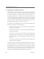
ADCCP NRM Line-Monitor Function
6.1
6.2
6.3
6.4
6.5
109
Opening and Attaching the Monitor Session .
Configuring the Line-Monitor Function . . .
Reporting Frames to the Client . . . . . . . .
Detaching and Closing the Monitor Session .
Line-Monitor Client Program (nrmmon) . .
.
.
.
.
.
.
.
.
.
.
.
.
.
.
.
.
.
.
.
.
.
.
.
.
.
.
.
.
.
.
.
.
.
.
.
.
.
.
.
.
.
.
.
.
.
.
.
.
.
.
.
.
.
.
.
.
.
.
.
.
.
.
.
.
.
.
.
.
.
.
.
.
.
.
.
109
110
111
114
115
A
Clock Signals
117
B
Error Codes
119
C
ADCCP NRM Loopback Test Programs
121
C.1 Loopback Test Programs (nrmalp and nrmtest) . . . . . . . . . . . . . . 121
C.2 Line Monitor Sample Program (nrmmon.c) . . . . . . . . . . . . . . . . 125
D
ADCCP NRM Detailed Command and Response Headers
D.1
D.2
D.3
D.4
D.5
D.6
D.7
D.8
D.9
D.10
D.11
D.12
D.13
D.14
D.15
D.16
D.17
6
Application Sequence of Events . . .
Command sequences . . . . . . . .
attach-packet . . . . . . . . . . . . .
set-buffer-size-packet . . . . . . . .
set-buffer-size-ack-packet . . . . . .
link-config-packet . . . . . . . . . .
station-config-packet . . . . . . . .
limit-config-packet. . . . . . . . . .
start-link-packet . . . . . . . . . . .
start-link-ack-packet. . . . . . . . .
start-station-packet . . . . . . . . .
start-station-ack-packet . . . . . . .
set-multipoint-list-packet (optional)
station-init-packet (optional) . . . .
station-init-ack-packet (optional). .
send-exchange-id-packet (optional)
recv-exchange-id-packet (optional) .
.
.
.
.
.
.
.
.
.
.
.
.
.
.
.
.
.
.
.
.
.
.
.
.
.
.
.
.
.
.
.
.
.
.
.
.
.
.
.
.
.
.
.
.
.
.
.
.
.
.
.
.
.
.
.
.
.
.
.
.
.
.
.
.
.
.
.
.
.
.
.
.
.
.
.
.
.
.
.
.
.
.
.
.
.
.
.
.
.
.
.
.
.
.
.
.
.
.
.
.
.
.
.
.
.
.
.
.
.
.
.
.
.
.
.
.
.
.
.
.
.
.
.
.
.
.
.
.
.
.
.
.
.
.
.
.
.
.
.
.
.
.
.
.
.
.
.
.
.
.
.
.
.
.
.
.
.
.
.
.
.
.
.
.
.
.
.
.
.
.
127
.
.
.
.
.
.
.
.
.
.
.
.
.
.
.
.
.
.
.
.
.
.
.
.
.
.
.
.
.
.
.
.
.
.
.
.
.
.
.
.
.
.
.
.
.
.
.
.
.
.
.
.
.
.
.
.
.
.
.
.
.
.
.
.
.
.
.
.
.
.
.
.
.
.
.
.
.
.
.
.
.
.
.
.
.
.
.
.
.
.
.
.
.
.
.
.
.
.
.
.
.
.
.
.
.
.
.
.
.
.
.
.
.
.
.
.
.
.
.
.
.
.
.
.
.
.
.
.
.
.
.
.
.
.
.
.
.
.
.
.
.
.
.
.
.
.
.
.
.
.
.
.
.
.
.
.
.
.
.
.
.
.
.
.
.
.
.
.
.
.
128
129
131
132
133
134
136
138
139
140
141
142
143
145
147
148
149
DC 900-1317J
Contents
D.18
D.19
D.20
D.21
D.22
D.23
D.24
D.25
D.26
D.27
D.28
D.29
D.30
D.31
D.32
D.33
D.34
D.35
D.36
D.37
D.38
D.39
D.40
D.41
D.42
station-reset-packet . . . . . . . . . . . . . . . . . . . . . . . . .
station-reset-ack-packet. . . . . . . . . . . . . . . . . . . . . . .
recv-station-reset-packet . . . . . . . . . . . . . . . . . . . . . .
recv-station-reset-ack-packet . . . . . . . . . . . . . . . . . . . .
write-unform-data-packet (or write-unform-data-eom-packet) .
receive-unform-data-packet . . . . . . . . . . . . . . . . . . . .
write-unnum-data-packet (or write-unnum-eom-data-packet) .
receive-unnum-data-packet. . . . . . . . . . . . . . . . . . . . .
write-data-packet . . . . . . . . . . . . . . . . . . . . . . . . . .
receive-data-packet . . . . . . . . . . . . . . . . . . . . . . . . .
resp-normal-ack-packet. . . . . . . . . . . . . . . . . . . . . . .
resp-local-ack-packet . . . . . . . . . . . . . . . . . . . . . . . .
buffer-rpt-packet . . . . . . . . . . . . . . . . . . . . . . . . . .
buffer-rpt-ack-packet . . . . . . . . . . . . . . . . . . . . . . . .
stats-rpt-packet . . . . . . . . . . . . . . . . . . . . . . . . . . .
stats-rpt-ack-packet . . . . . . . . . . . . . . . . . . . . . . . . .
version-rpt-packet. . . . . . . . . . . . . . . . . . . . . . . . . .
version-rpt-ack-packet . . . . . . . . . . . . . . . . . . . . . . .
recv-link-except-packet . . . . . . . . . . . . . . . . . . . . . . .
resp-error-packet . . . . . . . . . . . . . . . . . . . . . . . . . .
stop-station-packet . . . . . . . . . . . . . . . . . . . . . . . . .
stop-station-ack-packet . . . . . . . . . . . . . . . . . . . . . . .
stop-link-packet . . . . . . . . . . . . . . . . . . . . . . . . . . .
stop-link-ack-packet . . . . . . . . . . . . . . . . . . . . . . . .
detach-packet . . . . . . . . . . . . . . . . . . . . . . . . . . . .
Index
DC 900-1317J
.
.
.
.
.
.
.
.
.
.
.
.
.
.
.
.
.
.
.
.
.
.
.
.
.
.
.
.
.
.
.
.
.
.
.
.
.
.
.
.
.
.
.
.
.
.
.
.
.
.
.
.
.
.
.
.
.
.
.
.
.
.
.
.
.
.
.
.
.
.
.
.
.
.
.
.
.
.
.
.
.
.
.
.
.
.
.
.
.
.
.
.
.
.
.
.
.
.
.
.
. 150
. 151
. 152
. 153
. 154
. 156
. 157
. 159
. 160
. 162
. 163
. 164
. 165
. 166
. 168
. 169
. 170
. 171
. 172
. 173
. 174
. 175
. 176
. 177
. 178
179
7
ADCCP NRM Programmer’s Guide
8
DC 900-1317J
List of Figures
Figure 1–1: Freeway Configuration. . . . . . . . . . . . . . . . . . . . . . . . . . . . . 22
Figure 1–2: Embedded ICP Configuration. . . . . . . . . . . . . . . . . . . . . . . . . 23
Figure 1–3: A Typical Freeway Server Environment . . . . . . . . . . . . . . . . . . . . 25
Figure 2–1: Unbalanced Configuration . . . . . . . . . . . . . . . . . . . . . . . . . . 32
Figure 2–2: Balanced Configuration . . . . . . . . . . . . . . . . . . . . . . . . . . . . 33
Figure 2–3: Symmetric Configuration . . . . . . . . . . . . . . . . . . . . . . . . . . . 34
Figure 2–4: Operating Modes. . . . . . . . . . . . . . . . . . . . . . . . . . . . . . . . 40
Figure 3–1: “C” Definition of DLI Optional Arguments Structure . . . . . . . . . . . . 51
Figure 3–2: DLI_PROT_CFG_LINK Packet Data Area (Second Variant) . . . . . . . . . . . . 72
Figure 5–1: DLI and TSI Configuration Process . . . . . . . . . . . . . . . . . . . . . . 103
Figure 5–2: Example DLI Configuration File for Two Links . . . . . . . . . . . . . . . 105
Figure 6–1: Monitor Data Notification Header . . . . . . . . . . . . . . . . . . . . . . 111
Figure 6–2: Frame Abstract . . . . . . . . . . . . . . . . . . . . . . . . . . . . . . . . . 113
Figure D–1: SDLC_BUFFER_REPORT “C” Structure . . . . . . . . . . . . . . . . . . . 167
DC 900-1317J
9
ADCCP NRM Programmer’s Guide
10
DC 900-1317J
List of Tables
Table 1–1:
ADCCP NRM Data Rate and Number of Links . . . . . . . . . . . . . . . . 28
Table 2–1:
ADCCP Frame Types . . . . . . . . . . . . . . . . . . . . . . . . . . . . . . 39
Table 3–1:
Include Files for ADCCP NRM . . . . . . . . . . . . . . . . . . . . . . . . 44
Table 3–2:
DLI Call Sequence for ADCCP NRM (Blocking I/O). . . . . . . . . . . . . 47
Table 3–3:
DLI Call Sequence for ADCCP NRM (Non-blocking I/O) . . . . . . . . . . 48
Table 3–4:
DLI Functions: Syntax and Parameters (Listed in Typical Call Order). . . . 50
Table 3–5:
Client Packet dlWrite usProtCommand and iProtModifier Fields . . . . . . . . 53
Table 3–6:
ICP Packet dlRead usProtCommand and iProtModifier Fields . . . . . . . . . . 54
Table 3–7:
DLI_PROT_CFG_LINK Packet Data Area (First Variant)
Table 3–8:
DLI_PROT_CFG_LINK Packet Data Area (Third Variant)
Table 3–9:
Timer and Retry Parameter Default Values . . . . . . . . . . . . . . . . . . 77
. . . . . . . . . . . . . . 71
. . . . . . . . . . . . . 75
Table 3–10: ICP Statistics Packet Data Area Content . . . . . . . . . . . . . . . . . . . . 80
Table 3–11: Typical Arguments for the DLI_PROT_SET_BUF_SIZE Packet . . . . . . . . . . . 82
Table 5–1:
ADCCP NRM ICP Link Configuration Parameters for Using dlicfg . . . . . 106
Table A–1: EIA-232 Clock Signals . . . . . . . . . . . . . . . . . . . . . . . . . . . . . 117
Table B–1:
ADCCP NRM Error Codes. . . . . . . . . . . . . . . . . . . . . . . . . . . 120
Table C–1: Loopback Test Programs and Directories . . . . . . . . . . . . . . . . . . . 122
DC 900-1317J
11
ADCCP NRM Programmer’s Guide
12
DC 900-1317J
Preface
Purpose of Document
This document contains information for the development of applications that use Protogate’s ADCCP NRM software product in a Freeway communications server or
embedded ICP environment to establish communication with one or more remote stations.
Note
In this document, the term “Freeway” can mean either a Freeway
server or an embedded ICP. For the embedded ICP, also refer to
the user’s guide for your ICP and operating system (for example,
the ICP2432 User’s Guide for Windows NT).
Intended Audience
This document should be read by application programmers. You should be familiar
with some form of ADCCP protocol. You should also understand the Freeway data link
interface (DLI), as explained in the Freeway Data Link Interface Reference Guide.
Required Equipment
The ADCCP NRM product requires the following two major hardware components to
operate:
•
a Freeway communications server or an embedded ICP that runs the communications software
DC 900-1317J
13
ADCCP NRM Programmer’s Guide
•
a client computer that runs the following:
•
TCP/IP (for a Freeway server)
•
Freeway data link interface (DLI)
•
the user application program
Organization of Document
Chapter 1 is an overview of Freeway and the ADCCP NRM product.
Chapter 2 summarizes the ADCCP NRM communication protocol.
Chapter 3 describes how to write an ADCCP NRM application using the data link interface (DLI) to handle the command and response packets between the client application
program and the ADCCP NRM communications software running on the Freeway
ICP.
Chapter 4 describes ADCCP NRM operations.
Chapter 5 describes how to configure the ADCCP NRM link options using the dlicfg
program.
Chapter 6 describes the ADCCP NRM Line Monitor function.
Appendix A describes the clock signals for ADCCP NRM.
Appendix B lists the error codes and their causes.
Appendix C describes the ADCCP NRM loopback test program.
Appendix D details the ADCCP NRM command and response header formats.
14
DC 900-1317J
Preface
Protogate References
The following documents provide useful supporting information, depending on the
customer’s particular hardware and software environments. Most documents are
available on-line at Protogate’s web site, www.protogate.com.
General Product Overviews
•
•
•
•
Freeway 1100 Technical Overview
25-000-0419
Freeway 2000/4000/8800 Technical Overview
25-000-0374
ICP2432 Technical Overview
25-000-0420
ICP6000X Technical Overview
25-000-0522
Hardware Support
•
•
•
Freeway 1100/1150 Hardware Installation Guide
DC 900-1370
Freeway 1200 Hardware Installation and Maintenance Guide
DC 900-1537
•
•
Freeway 1300 Hardware Installation and Maintenance Guide
•
•
•
•
•
Freeway 2000/4000 Hardware Installation Guide
DC 900-1331
Freeway 8800 Hardware Installation Guide
DC 900-1553
Freeway 2000/4000 Hardware Maintenance Guide
DC 900-1332
Freeway ICP6000R/ICP6000X Hardware Description
DC 900-1020
ICP6000(X)/ICP9000(X) Hardware Description and Theory of
Operation
DC 900-0408
•
•
•
ICP2424 Hardware Description and Theory of Operation
DC 900-1328
ICP2432 Hardware Description and Theory of Operation
DC 900-1501
ICP2432 Hardware Installation Guide
DC 900-1502
Freeway 1200 Hardware Installation and Maintenance Guide for DC 900-1542
OEMs
DC 900-1539
Freeway 1300 Hardware Installation and Maintenance Guide for DC 900-1541
OEMs
Freeway Software Installation Support
•
•
•
Freeway Software Release Addendum: Client Platforms
DC 900-1555
Freeway User’s Guide
DC 900-1333
Getting Started with Freeway 1100/1150
DC 900-1369
DC 900-1317J
15
ADCCP NRM Programmer’s Guide
•
•
•
•
•
Getting Started with Freeway 1200
DC 900-1536
Getting Started with Freeway 1300
DC 900-1538
Getting Started with Freeway 2000/4000
DC 900-1330
Getting Started with Freeway 8800
DC 900-1552
Loopback Test Procedures
DC 900-1533
Embedded ICP Installation and Programming Support
•
•
•
•
•
ICP2432 User’s Guide for Digital UNIX
DC 900-1513
ICP2432 User’s Guide for OpenVMS Alpha
DC 900-1511
ICP2432 User’s Guide for OpenVMS Alpha (DLITE Interface)
DC 900-1516
ICP2432 User’s Guide for Windows NT
DC 900-1510
ICP2432 User’s Guide for Windows NT (DLITE Interface)
DC 900-1514
Application Program Interface (API) Programming Support
•
•
•
Freeway Data Link Interface Reference Guide
DC 900-1385
Freeway Transport Subsystem Interface Reference Guide
DC 900-1386
QIO/SQIO API Reference Guide
DC 900-1355
Socket Interface Programming Support
•
Freeway Client-Server Interface Control Document
DC 900-1303
Toolkit Programming Support
•
Freeway Server-Resident Application and Server Toolkit Program- DC 900-1325
mer’s Guide
•
•
OS/Impact Programmer’s Guide
DC 900-1030
Protocol Software Toolkit Programmer’s Guide
DC 900-1338
Protocol Support
•
•
•
•
•
•
16
ADCCP NRM Programmer’s Guide
DC 900-1317
Asynchronous Wire Service (AWS) Programmer’s Guide
DC 900-1324
Addendum: Embedded ICP2432 AWS Programmer’s Guide
DC 900-1557
BSC Programmer’s Guide
DC 900-1340
BSCDEMO User’s Guide
DC 900-1349
BSCTRAN Programmer’s Guide
DC 900-1406
DC 900-1317J
Preface
•
•
•
•
•
•
•
•
•
DDCMP Programmer’s Guide
DC 900-1343
FMP Programmer’s Guide
DC 900-1339
Freeway AUTODIN Programmer’s Guide
DC 908-1558
Freeway SIO STD-1300 Programmer’s Guide
DC 908-1559
Military/Government Protocols Programmer’s Guide
DC 900-1602
SIO STD-1200A (Rev. 1) Programmer’s Guide
DC 908-1359
X.25 Call Service API Guide
DC 900-1392
X.25/HDLC Configuration Guide
DC 900-1345
X.25 Low-Level Interface
DC 900-1307
Document Conventions
This document follows the most significant byte first (MSB) and most significant word
first (MSW) conventions for byte-ordering. Bits are numbered from the least significant to the most significant (bit 0 is the least significant bit). In all packet transfers
between the client computer system and the Freeway processor, the ordering of the byte
stream is preserved. Processes on the client computer are never required to perform
byte stream manipulation regardless of the hardware configuration.
The term “Freeway” refers to any of the Freeway server models (for example, Freeway
500/3100/3200/3400 PCI-bus servers, Freeway 1000 ISA-bus servers, or Freeway
2000/4000/8800 VME-bus servers). References to “Freeway” also may apply to an
embedded ICP product using DLITE (for example, the embedded ICP2432 using
DLITE on a Windows NT system).
Physical “ports” on the ICPs are logically referred to as “links.” However, since port and
link numbers are usually identical (that is, port 0 is the same as link 0), this document
uses the term “link.”
Program code samples are written in the “C” programming language.
DC 900-1317J
17
ADCCP NRM Programmer’s Guide
Revision History
The revision history of the ADCCP NRM Programmer’s Guide, Protogate document
DC 900-1317J, is recorded below:
Revision
Release Date
Description
DC 900-1317A
September 1994
Preliminary release
DC 900-1317B
November 1994
Full release:
• Minor modifications and updated error codes
• Updated file names for software release 2.1
• Change the usICPStatus field to iICPStatus and change the
usProtModifier field to iProtModifier (page 51)
DC 900-1317C
May 1995
Minor modifications
DC 900-1317D
January 1996
Minor modifications throughout document
Add new dlControl function to Table 3–4 on page 50
Add Windows NT to Chapter 5 and Appendix C
DC 900-1317E
October 1997
Add Freeway browser interface
Add new dlpErrString function (Table 3–4 on page 50)
Minor changes to Chapter 5 and Appendix C
DC 900-1317F
July 1998
Modify Section 1.1 through Section 1.4 for embedded ICPs
Remove browser interface support
Minor changes to Section 3.1.2 on page 45 and Section 3.2 on page 47
Add dlSyncSelect function (Table 3–4 on page 50)
Minor changes to Chapter 5 and Appendix C
DC 900-1317G
November 1998
Add Appendix D, “ADCCP NRM Detailed Command and Response
Headers”
DC 900-1317H
December 1998
Modifications to ADCCP option 7 (page 74 and page 74)
DC 900-1317I
February 1999
Add new client and ICP packets (Table 3–5 on page 53 and Table 3–6 on
page 54) and corresponding packet formats in Appendix D:
DLI_PROT_SEND_UNFORMATTED_DATA_EOM,
DLI_PROT_SEND_UNNUMBERED_DATA_EOM,
DLI_PROT_GET_BUF_REPORT, DLI_PROT_RESP_BUF_REPORT, and
DLI_PROT_RESP_LOCAL_ACK.
DC 900-1317J
April 2005
Updated contact information for Protogate.
Added “DCD Lost” and “DCD Gained” Link Exception notifications
(Table 3–6 on page 54, Section D.36 on page 172).
Added the configuration of the electrical interface for a link
(Section 3.4.20.1 on page 70).
Added ADCCP NRM Line Monitor function (Chapter 6, Section C.2 on
page 125).
18
DC 900-1317J
Preface
Customer Support
If you are having trouble with any Protogate product, call us at (858) 451-0865 Monday
through Friday between 8 a.m. and 5 p.m. Pacific time.
You can also fax your questions to us at (877) 473-0190 any time. Please include a cover
sheet addressed to “Customer Service.”
We are always interested in suggestions for improving our products. You can use the
report form in the back of this manual to send us your recommendations.
DC 900-1317J
19
ADCCP NRM Programmer’s Guide
20
DC 900-1317J
Chapter
1
Introduction
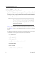
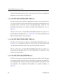
1.1 Product Overview
Protogate provides a variety of wide-area network (WAN) connectivity solutions for
real-time financial, defense, telecommunications, and process-control applications.
Protogate’s Freeway server offers flexibility and ease of programming using a variety of
LAN-based server hardware platforms. Now a consistent and compatible embedded
intelligent communications processor (ICP) product offers the same functionality as
the Freeway server, allowing individual client computers to connect directly to the
WAN.
Both Freeway and the embedded ICP use the same data link interface (DLI). Therefore,
migration between the two environments simply requires linking your client application with the proper library. Various client operating systems are supported (for example, UNIX, VMS, and Windows NT).
Protogate protocols that run on the ICPs are independent of the client operating system
and the hardware platform (Freeway or embedded ICP).
1.1.1 Freeway Server
Protogate’s Freeway communications servers enable client applications on a local-area
network (LAN) to access specialized WANs through the DLI. The Freeway server can be
any of several models (for example, Freeway 3100, 3200, 3400, or 3600). The Freeway
server is user programmable and communicates in real time. It provides multiple data
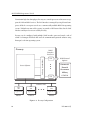
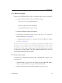
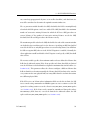
links and a variety of network services to LAN-based clients. Figure 1–1 shows the
Freeway configuration.
DC 900-1317J
21
ADCCP NRM Programmer’s Guide
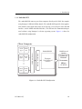
To maintain high data throughput, Freeway uses a multi-processor architecture to support the LAN and WAN services. The LAN interface is managed by a single-board computer, called the server processor. It uses a commercially available BSD Unix operating
system (VxWorks on some older systems) to provide a full-featured base for the LAN
interface and layered services needed by Freeway.
Freeway can be configured with multiple WAN interface processor boards, each of
which is a Protogate ICP. Each ICP runs the communication protocol software using
Protogate’s real-time operating system.
Freeway
WAN Protocol
Options
●
Commercial
Financial
Government
●
Server Software
ICP
●
Industry Standard Bus
WAN
Interface
Processors
Military
SCADA
ICP
Ethernet LAN
DLI
API
Application
Application
Application
Client 1
Client 2
Client n
●
●
●
DLI
API
3413
DLI
API
Figure 1–1: Freeway Configuration
22
DC 900-1317J
1: Introduction
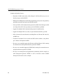
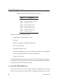
1.1.2 Embedded ICP
The embedded ICP connects your client computer directly to the WAN (for example,
using Protogate’s ICP2432 PCIbus board). The embedded ICP provides client applications with the same WAN connectivity as the Freeway server, using the same data link
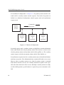
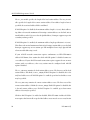
interface (via the DLITE embedded interface). The ICP runs the communication protocol software using Protogate’s real-time operating system. Figure 1–2 shows the
embedded ICP configuration.
Client Computer
Client DLITE
API
Appl 1
ICP Device Driver
Industry Standard Bus
●
●
●
Client DLITE
API
Appl 2
WAN Protocol
Options
Embedded ICP
Commercial
Financial
Government
Protogate
WAN Protocol
Software
Military
SCADA
3414
Client DLITE
Appl n
API
Figure 1–2: Embedded ICP Configuration
DC 900-1317J
23
ADCCP NRM Programmer’s Guide
Summary of product features:
•
Provision of WAN connectivity either through a LAN-based Freeway server or
directly using an embedded ICP
•
Elimination of difficult LAN and WAN programming and systems integration by
providing a powerful and consistent data link interface
•
Variety of off-the-shelf communication protocols available from Protogate which
are independent of the client operating system and hardware platform
•
Support for multiple WAN communication protocols simultaneously
•
Support for multiple ICPs (two, four, or eight communication lines per ICP)
•
Wide selection of electrical interfaces including EIA-232, EIA-449, EIA-530, V.35,
and MIL-188
•
Creation of customized server-resident and ICP-resident software, using Protogate’s software development toolkits
•
Freeway server standard support for Ethernet and Fast Ethernet LANs running
the transmission control protocol/internet protocol (TCP/IP)
•
Freeway server standard support for FDDI LANs running the transmission control protocol/internet protocol (TCP/IP)
•
Freeway server management and performance monitoring with the simple network management protocol (SNMP), as well as interactive menus available
through a local console, telnet, or rlogin
24
DC 900-1317J
1: Introduction
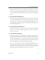
1.2 Freeway Client-Server Environment
The Freeway server acts as a gateway that connects a client on a local-area network to a
wide-area network. Through Freeway, a client application can exchange data with a
remote data link application. Your client application must interact with the Freeway
server and its resident ICPs before exchanging data with the remote data link application.
One of the major Freeway server components is the message multiplexor (MsgMux)
that manages the data traffic between the LAN and the WAN environments. The client
application typically interacts with the Freeway MsgMux through a TCP/IP BSD-style
socket interface (or a shared-memory interface if it is a server-resident application
(SRA)). The ICPs interact with the MsgMux through the DMA and/or shared-memory
interface of the industry-standard bus to exchange WAN data. From the client application’s point of view, these complexities are handled through a simple and consistent
data link interface (DLI), which provides dlOpen, dlWrite, dlRead, and dlClose functions.
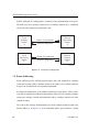
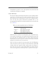
Figure 1–3 shows a typical Freeway connected to a locally attached client by a TCP/IP
network across an Ethernet LAN interface. Running a client application in the Freeway
client-server environment requires the basic steps described in Section 1.4.
Client
Application DLI TSI
TCP/IP
TCP/IP
Socket Interface
client_1
192.52.107.99
Freeway
SRA
T
S msgmux
I
ICP0
ICP1
WAN
protocols
ICP2
ICP3
3125
Shared Memory
Interface
Ethernet
Industry
Standard Bus
Client
freeway_0
192.52.107.100
Figure 1–3: A Typical Freeway Server Environment
DC 900-1317J
25
ADCCP NRM Programmer’s Guide
1.2.1 Establishing Freeway Server Internet Addresses
The Freeway server must be addressable in order for a client application to communicate with it. In the Figure 1–3 example, the TCP/IP Freeway server name is freeway2,
and its unique Internet address is 192.52.107.100. The client machine where the client
application resides is client1, and its unique Internet address is 192.52.107.99. Refer to
the Freeway User’s Guide to initially set up your Freeway and download the operating
system, server, and protocol software to Freeway.
1.3 Embedded ICP Environment
Refer to the user’s guide for your embedded ICP and operating system (for example, the
Freeway Embedded ICP2432 User’s Guide for Windows NT) for software installation and
setup instructions. The user’s guide also gives additional information regarding the data
link interface (DLI) and embedded programming interface descriptions for your specific embedded environment. Refer back to Figure 1–2 on page 23 for a diagram of the
embedded ICP environment. Running a client application in the embedded ICP environment requires the basic steps described in Section 1.4
1.4 Client Operations
Client application communication with the Freeway takes place over the Data Link
Interface (DLI) sessions and their underlying Transport Subsystem Interface (TSI) connections. Communication with the embedded ICP uses the DLI but not the TSI.
1.4.1 Defining the DLI and TSI Configuration
You must define the DLI sessions and TSI connections between your client application
and Freeway (only the DLI sessions for an embedded ICP). To accomplish this, you first
define the configuration parameters in DLI and TSI ASCII configuration files; then you
run two preprocessor programs, dlicfg and tsicfg, to create binary configuration files
(see Chapter 5). The dlInit function uses the binary configuration files to initialize the
DLI environment. (The dlTerm function terminates the DLI environment.)
26
DC 900-1317J
1: Introduction
1.4.2 Opening a Session
After the DLI and TSI configurations are properly defined, your client application uses
the dlOpen function to establish a DLI session with an ICP link. As part of the session
establishment process, the DLI establishes a TSI connection with the Freeway MsgMux
through the TCP/IP BSD-style socket interface for the Freeway server, or directly to the
client driver for the embedded ICP environment.
1.4.3 Exchanging Data with the Remote Application
After the link is enabled, the client application can exchange data with the remote application using the dlWrite and dlRead functions.
1.4.4 Closing a Session
When your application finishes exchanging data with the remote application, it calls the
dlClose function to disable the ICP link, close the session with the ICP, and disconnect
from Freeway (or the embedded ICP).
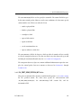
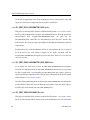
1.5 ADCCP NRM Overview
Protogate’s ADCCP NRM is a layered software product that runs on Protogate’s Intelligent Communications Processor (ICP). It interacts with the client application software to achieve station-to-station communications in an unbalanced (multidrop)
configuration. ADCCP NRM protocol requirements are handled by the ADCCP NRM
software on the ICP. The application programmer need only handle ICP initialization
and exception conditions in addition to application-level data transfer concerns.
Protogate’s ADCCP NRM interface implements the American National Standard for
Advanced Data Communication Control Procedures (ADCCP) in normal response
mode (NRM) operation as defined in ANSI publication X3.66-1979. The software on
the ICP handles the low-level protocol interface requirements of the ADCCP NRM protocol, thus freeing clients from this CPU-intensive activity. The software presents packets of data to your application program through the DLI sessions.
DC 900-1317J
27
ADCCP NRM Programmer’s Guide
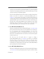
Each serial port (link) on the ICP operates independently of the other links on the same
ICP and can be configured with different communication options. For example, each
data link may be configured to run at its own baud rate, ranging from 1.2 kb/s to
122.9 kb/s with internal clock, or to 128 kb/s with external clock. Protogate’s ADCCP
NRM Primary may be configured to poll up to 128 remote secondary stations. Stations
are configurable and may be assigned to any chosen link (physical port) on the ICP.
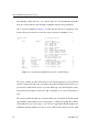
Because of the complexity of the ADCCP protocol and the speed limitations on character interrupt servicing on the ICP, the peak data transfer rate on all ports combined cannot exceed the nominal baud rates given in Table 1–1.
Table 1–1: ADCCP NRM Data Rate and Number of Links
Data Rate
(b/s)
ICP2432/
ICP2432B
2400 or less
8 links
4800
8 links
9600
8 links
19200
8 links
38400
8 links
64000
8 links
122880
128000
4 links
1
2 links
1
An external clock source is
required at 128000 baud.
28
DC 900-1317J
1: Introduction
1.5.1 Software Description
Protogate’s ADCCP NRM product includes the following major software components:
•
A group of communications software downloadable images:
1. Freeway server or embedded ICP software
2. Real-time operating system (OS/Impact)
3. ADCCP NRM communications software
•
DLI library for linking with client applications
•
Two loopback test programs (nrmalp.c nrmtest.c and nrmtest.c) for checking the
product installation (see Appendix C)
•
A sample program (nrmmon.c) for operating the ADCCP NRM Line Monitor
function (see Appendix C)
The Freeway User’s Guide or the user’s guide for your particular embedded ICP and
operating system (for example, the Freeway Embedded ICP2432 User’s Guide for Windows NT) describes the software installation procedures. The DLI provides an interface
by which data is exchanged between the client application and Freeway; refer to the
Freeway Data Link Interface Reference Guide.
1.5.2 Hardware Description
A typical Freeway configuration of Protogate’s ADCCP NRM product requires the following hardware:
•
Communications server processor (for example, Freeway 3100, 3200, 3400, or
3600) or an embedded ICP (for example, the PCIbus ICP2432B)
•
Ethernet connection to a client running TCP/IP (for a Freeway server)
DC 900-1317J
29
ADCCP NRM Programmer’s Guide
30
DC 900-1317J
Chapter
2
ADCCP NRM Protocol
Summary
Protogate’s ADCCP NRM interface product is based on the American National Standard for Advanced Data Communication Control Procedures (ADCCP), which is a
standard protocol (ANSI X3.66-1979) that helps computers exchange information.
ADCCP defines link-level operation in several distinctly different configurations and
operating modes. ADCCP also supports eleven optional features that modify link-level
operation.
The following discussion refers to the normal response mode (NRM), asynchronous
response mode (ARM), and asynchronous balanced mode (ABM) of ADCCP operation. Note, however, that the communications package you have purchased supports
NRM only. ADCCP option 10 may be used to convert to an extended mode (NRME)
that allows longer delays between data transmission and data acknowledgment on the
link.
This chapter describes the ADCCP protocol in general (including features that may not
be supported in your package) and defines the normal environment in which ADCCP
is used. This information is provided solely for your interest and is not required for use
of this communications package.
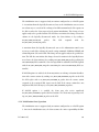
2.1 Unbalanced Configurations
Some applications require a primary station to control and exchange information with
one or more secondary stations on a single data link. ADCCP achieves this by defining
a set of procedures for unbalanced mode operation.
DC 900-1317J
31
ADCCP NRM Programmer’s Guide
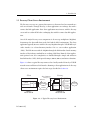
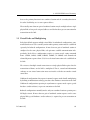
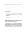
In an unbalanced configuration (see Figure 2–1), the primary station transmits commands and the secondary stations transmit responses. Two modes of operation are
defined in an unbalanced configuration: normal response mode and asynchronous
response mode.
Commands
Responses
Primary
Station
on link
Secondary
Station
A
Secondary
Station
B
(optional)
Secondary
Station
C
(optional)
DRWG-0526
Figure 2–1: Unbalanced Configuration
In normal response mode, secondary stations are forbidden to transmit information
frames until invited to do so by the primary station. This invitation to transmit occurs
when the primary station sends any frame with the P-bit (poll bit) set. The secondary
station’s response ends when it transmits a frame with the F-bit (final bit) set.
In asynchronous response mode, the secondary stations may send unsolicited information frames at any time. These information frames contain an F-bit that is reset to zero.
However, when a secondary station receives (from the primary station) a command
frame that has the P-bit set to one, the secondary station must respond as soon as possible with a frame that has the F-bit set to one. If multiple secondary stations are configured for ARM operation, special hardware is required to prevent contention on the
link.
32
DC 900-1317J
2: ADCCP NRM Protocol Summary
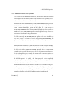
2.2 Balanced Configurations
Some applications require two stations (one local and one remote) to exchange control
and information. ADCCP achieves this by defining a set of procedures for balanced
mode operation.
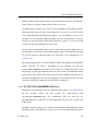
A balanced configuration (see Figure 2–2) operates in asynchronous balanced mode,
which functions much as if each station contained both a primary station and a secondary station operating in asynchronous response mode. However, in ADCCP each combined station is considered to be a single station, so that a link between two combined
stations is established if and only if the primary function in each communicates with the
secondary function in the other. That is, the link is not established unless it is truly balanced.
Station A Commands
Station B Responses
Local
Combined
Station
A
Remote
Combined
Station
B
Station B Commands
Station A Responses
DRWG-0527
Figure 2–2: Balanced Configuration
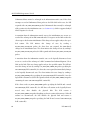
2.3 Symmetric Configurations
A symmetric configuration (see Figure 2–3) is much like a balanced configuration,
except that four stations (two primary and two secondary) and two virtual data links are
DC 900-1317J
33
ADCCP NRM Programmer’s Guide
defined. Although the configuration is symmetric, link communications may not be.
The link between one primary station and its secondary station may be established,
whereas the other primary/secondary link is not.
Local
Primary
Station
A
Station A Commands
Station B Responses
Local
Secondary
Station
C
Station D Commands
Station C Responses
Remote
Secondary
Station
B
Remote
Primary
Station
D
DRWG-0528
Figure 2–3: Symmetric Configuration
2.4 Frame Addressing
Frame addressing in the ADCCP protocol requires that each combined or secondary
station have a unique address. Primary stations use the address of a secondary station to
designate the destination of each transmitted command.
In a balanced configuration, each combined station has its own address. This is consistent with the analogy that combined stations behave much as if each contains a primary
station that exchanges control and information with a secondary station in the other
combined station.
The result is that exchange of information between two combined stations requires two
distinct addresses. In Figure 2–2, each command/response pair constitutes a dialog
34
DC 900-1317J
2: ADCCP NRM Protocol Summary
between the primary function in one combined station and the secondary function in
the other. Each dialog uses its own separate address.
Theoretically, more than one pair of combined stations may be multiplexed on a single
physical link, so long as the assigned addresses and the hardware prevent contention for
transmission on the link.
2.5 Virtual Links and Multiplexing
Each physical link supports multiple virtual links. In unbalanced configurations, communication between each secondary station and its primary station must be established
separately. In balanced configurations, if more than one pair of combined stations is
configured on the same physical link, each pair must establish communication independently. Each of these configurations requires a separate mode setting command
frame (SNRM, SARM, SABM, SNRME, SARME, or SABME) and unnumbered
acknowledgment response frame (UA) for each virtual connection to be established on
the link.
The existence of multiple virtual connections on a single physical link requires that the
transmission of frames on the link be multiplexed. That is, control and information
exchange on one virtual connection must not interfere with that on another virtual
connection.
Unbalanced configurations that operate in normal response mode handle multiplexing
by defining an information exchange procedure that eliminates contention on the link.
Unbalanced configurations operating in asynchronous response mode require special
hardware (and/or software) to prevent contention on the link.
Balanced configurations normally involve only two combined stations operating on a
full duplex circuit. If more than one pair of combined stations operates on the same
physical link, special hardware (and/or software) is required to prevent contention on
the link.
DC 900-1317J
35
ADCCP NRM Programmer’s Guide
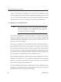
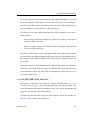
2.6 Operational States
ADCCP link operation procedures define three fundamental states: logically disconnected state, initialization state, and information transfer state. Within each state,
ADCCP defines valid link operation procedures.
In the logically disconnected state, only unnumbered frames are valid. Information
frames and supervisory frames are ignored. Consequently, no information is exchanged
in this state. Link operation always starts in the logically disconnected state.
The initialization state, which is optional, can be used when support for set initialization mode (SIM) commands and request initialization mode (RIM) responses is
requested (ADCCP option 5). Link operation procedures in this state are not well
defined. This state is provided to allow implementers some freedom to initialize or
download equipment prior to starting data transfer. It allows exchange of unformatted
and unchecked bit streams.
The information transfer state allows the exchange of information and control frames.
The procedures for link operation in this state vary according to the operating mode
(NRM, ARM, or ABM) and the optional ADCCP functions selected. Within the information state, procedures are defined for information transfer, sequence number validation, data transfer acknowledgment, and error recovery.
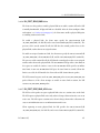
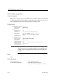
2.7 Optional Functions
ADCCP defines eleven optional functions. Each one affects link operation by adding or
deleting procedural requirements. These optional functions are summarized as follows:
OPTION 1
This option provides the ability to exchange station identification by
means of an unnumbered exchange identification (XID) command/response frame. Option 1 also defines an unnumbered request
disconnect (RD) response that allows a secondary station (or a secondary function in a combined station) to request the primary station
36
DC 900-1317J
2: ADCCP NRM Protocol Summary
(or function) to issue a disconnect (DISC) command. This option is
not normally used in ARM or ABM operation, but may be used in
NRM operation in a multidrop unbalanced configuration.
OPTION 2
This option improves error recovery by defining a reject (REJ) supervisory command/response frame that reports sequence number
errors. An REJ response triggers sequential retransmission of information frames, beginning with the lost frame.
OPTION 3
This option refines option 2 recovery procedures by defining a selective reject (SREJ) supervisory command/response frame that triggers
retransmission of the missing frame only.
OPTION 4
This option supports exchange of unnumbered information frames
by defining unnumbered information (UI) command/response
frames. Data exchanged via UI frames is not acknowledged and is
therefore unprotected from data loss. No error recovery procedures
exist for UI frames.
OPTION 5
This option provides support for the optional initialization state by
defining SIM command frames and RIM response frames. Initialization mode is set as a result of an SIM/UA exchange initiated by the
primary station. The secondary station may request the primary station to set initialization mode by transmitting the RIM response.
OPTION 6
This option defines the unnumbered poll (UP) command to support
unnumbered polling. The primary station transmits UP command
frames to invite the secondary station to transmit information. Unlike
a polling receive ready (RR) command frame, the UP command
frame does not acknowledge previous transmissions.
OPTION 7
This option defines a recursively expandable address field to allow
frame addressing to exceed the normal size of one octet.
DC 900-1317J
37
ADCCP NRM Programmer’s Guide
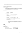
OPTION 8
This option forbids the use of information response frames. This
implies that a secondary station cannot send information frames to its
primary station. This option is normally used during ABM operation,
in which combined stations always send I-frames as command
frames.
OPTION 9
This option forbids the use of information command frames. This
implies that a primary station cannot send information frames to any
secondary stations.
OPTION 10
This option defines an extended control field that supports modulo
128 sequence numbers. This allows the link to send up to 127 (instead
of 7) I-frames before requiring acknowledgment.
OPTION 11
This option forbids the use of the reset (RSET) command in ABM
operation. This removes the ability to reset send and receive variables
associated with only one direction of information flow. This option
does not apply to NRM or ARM operation (in which the RSET command does not exist), but is normally used in ABM operation.
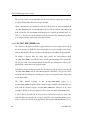
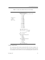
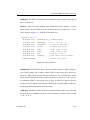
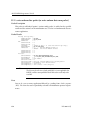
2.8 Summary of Frame Types
ADCCP defines a command frame as any frame sent by the primary station to a secondary station. A response frame is any frame sent by a secondary station to its primary station. In balanced configurations, the same definition holds true for frames exchanged
between the primary and secondary functions within different combined stations.
Table 2–1 summarizes these frame types.
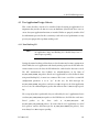
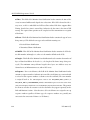
2.9 Summary of NRM, ARM, and ABM
The three operational modes (NRM, ARM, and ABM) mentioned in Section 2.1 and
Section 2.2 may be viewed as three overlapping sets of link operation rules as shown in
38
DC 900-1317J
2: ADCCP NRM Protocol Summary
Table 2–1: ADCCP Frame Types
Information Transfer Format Commands/Responses
I
Information
Supervisory Format Commands/Responses
RR
Receive ready
RNR
Receive not ready
REJ
Reject
SREJ
Selective reject
Unnumbered Format Commands
SNRM
Set normal response mode
SARM
Set asynchronous response mode
SABM
Set asynchronous balanced mode
SNRME
Set normal response mode extended
SARME
Set asynchronous response mode extended
SABME
Set asynchronous balanced mode extended
SIM
Set initialization mode
DISC
Disconnect
UI
Unnumbered information
UP
Unnumbered poll
RSET
Reset (ABM operation only)
XID
Exchange identification
Unnumbered Format Responses
DC 900-1317J
UA
Unnumbered acknowledgment
DM
Disconnected mode
RIM
Request initialization mode
UI
Unnumbered information
FRMR
Frame reject
XID
Exchange identification
RD
Request disconnect
39
ADCCP NRM Programmer’s Guide
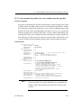
Figure 2–4. The major areas of difference occur in the handling of polling, F-bit
responses, checkpoint retransmission, and timers. This section describes these differences, and explains the reason for their existence.
NRM
Delayed F-bit Response
Primary Polling
ARM
P-bit Checkpoint
Secondary T2 Timer
Primary T1
Timer and
F-bit
Checkpoint
Immediate
F-bit Response
ABM
DRWG-1136
Figure 2–4: Operating Modes
40
DC 900-1317J
2: ADCCP NRM Protocol Summary
Because normal response mode (NRM) operation is usually used in a multidrop unbalanced configuration, primary station polling is necessary. For the secondary station to
efficiently transmit information back to the primary station, the secondary station usually delays its F-bit response to the primary station’s P-bit poll. This lets the secondary
station send several I-frames to the primary station before terminating the transmission
with a frame containing an F-bit. In Figure 2–4, delayed F-bit response and primary station polling operations are shown as unique to NRM operation.
Figure 2–4 shows that the T1 timer function for primary station (or balanced station
primary function) operation is shared by all modes (NRM, ARM, and ABM). A primary
station uses the T1 timer to detect the absence of poll responses or I-frame acknowledgment.
In asynchronous response mode (ARM), the secondary station may send unsolicited Iframes to the primary station. Therefore, a secondary timer function is required to initiate recovery from conditions in which a previous I-frame transmission is not
acknowledged. Figure 2–4 shows this secondary timer requirement as the T2 timer;
however, no T2 timer is required in ARM operation if ADCCP option 8 is enabled, preventing the secondary station from sending response I-frames.
In asynchronous modes (ARM and ABM), the secondary station (or balanced station
secondary function in ABM mode) is allowed to send unsolicited frames to the primary
station. Because nothing is gained by delaying the F-bit response, the secondary station
sends an immediate F-bit response to any P-bit received. Figure 2–4 shows the immediate F-bit response as a shared attribute of ARM and ABM modes.
ADCCP defines checkpoint recovery operations in which the primary or secondary station initiates retransmission of unacknowledged I-frames. These procedures ensure
data retransmission in the absence of acknowledgment or REJ/SREJ recovery procedures.
DC 900-1317J
41
ADCCP NRM Programmer’s Guide
F-bit checkpoint recovery occurs when the primary station receives a supervisory frame
or I-frame with the F-bit set and finds that the N(R) field in the received frame does not
acknowledge the N(S) field in the last I-frame the primary station sent with the P-bit
set. Figure 2–4 shows that F-bit checkpoint recovery is shared by all three modes (NRM,
ARM, and ABM).
P-bit checkpoint recovery occurs when the secondary station receives a supervisory
frame or I-frame with the P-bit set and finds that the N(R) field in the received frame
does not acknowledge the N(S) field in the last I-frame the secondary station sent with
the F-bit set. Figure 2–4 shows that P-bit checkpoint recovery is shared by the NRM and
ARM modes only. The ABM mode does not use P-bit recovery.
42
DC 900-1317J
Chapter
3
Note
ADCCP NRM
DLI Functions
In this document, the term “Freeway” can mean either a Freeway
server or an embedded ICP. For the embedded ICP, also refer to
the user’s guide for your ICP and operating system (for example,
the ICP2432 User’s Guide for Windows NT).
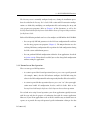
This chapter describes how to use the data link interface (DLI) functions to write client
applications interfacing to the Freeway ADCCP NRM protocol software. You should be
familiar with the concepts described in the Freeway Data Link Interface Reference Guide;
however, some summary information is provided in Section 3.1.
The following might be helpful references while reading this chapter:
•
Section 3.2 compares a typical sequence of DLI function calls using blocking versus non-blocking I/O.
•
Appendix B explains error handling and provides a summary table for ADCCP
NRM error codes. The Freeway Data Link Interface Reference Guide gives complete DLI error code descriptions.
•
The Freeway Data Link Interface Reference Guide provides a generic code example
which can guide your application program development, along with the programs described in Appendix C of this manual.
DC 900-1317J
43
ADCCP NRM Programmer’s Guide
•
The various mnemonic codes mentioned throughout this document are defined
in the include files provided with this product, which are described in Table 3–1.
Table 3–1: Include Files for ADCCP NRM
Description
Include File
DLI_PROT_* codes
dliprot.h
DLI_ICP_ERR_* codes
dlicperr.h
DLI_ICP_CMD_* codes
dliicp.h
FW_* codes
freeway.h
3.1 Summary of DLI Concepts
The DLI presents a consistent, high-level, common interface across multiple clients,
operating systems, and transport services. It implements functions that permit your
application to use data link services to access, configure, establish and terminate sessions, and transfer data across multiple data link protocols. The DLI concepts are
described in detail in the Freeway Data Link Interface Reference Guide. This section summarizes the basic information.
3.1.1 Configuration in the Freeway Environment
Several items must be configured before a client application can run in the Freeway
environment:
44
•
Freeway server configuration
•
data link interface (DLI) session configuration
•
transport subsystem interface (TSI) connection configuration
•
protocol-specific ICP link configuration
DC 900-1317J
3: ADCCP NRM DLI Functions
The Freeway server is normally configured only once, during the installation procedures described in the Freeway User’s Guide. DLI session and TSI connection configurations are defined by modifying text configuration files and running the dlicfg and
tsicfg preprocessor programs. Refer to Chapter 5 of this document, as well as the
Freeway Data Link Interface Reference Guide and the Freeway Transport Subsystem Interface Reference Guide.
Either of the following methods can be used to configure an ICP link for ADCCP NRM:
•
You can specify ICP link parameters in the DLI text configuration file and then
run the dlicfg preprocessor program (Chapter 5). The dlOpen function uses the
resulting DLI binary configuration file to perform the link configuration during
the DLI session establishment process.
•
You can perform ICP link configuration within the client application (described
in Section 3.4.20). This method is useful if you need to change link configuration
without exiting the application.
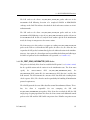
3.1.2 Normal versus Raw Operation
There are two types of DLI operation:
•
A session is opened for Normal operation if you set protocol to a specific protocol
(for example, “NRM”); then the DLI software configures the ICP links using the
values in the DLI configuration file and transparently handles all headers and I/O.
•
A session is opened for Raw operation if you set protocol to “raw”; then your application must handle all configuration, headers, and I/O details. Refer to the
Freeway Data Link Interface Reference Guide if you need to use Raw operation.
To read and write using Normal operation, your client application typically interacts
with Freeway only for the purpose of exchanging data with the remote application.
However, if your client application needs to interact with Freeway to obtain status or
reports, or to provide Freeway with protocol-specific information relating to the data
DC 900-1317J
45
ADCCP NRM Programmer’s Guide
exchange, Normal and Raw operation can be mixed. The client application session
should be configured for Normal operation (allowing DLI to handle some of the headers), but the read and write requests can use Raw operation by including the optional
arguments structure (Section 3.3) containing the protocol-specific information.
3.1.3 Blocking versus Non-blocking I/O
Note
Earlier Freeway releases used the term “synchronous” for blocking
I/O and “asynchronous” for non-blocking I/O. Some parameter
names reflect the previous terminology.
Non-blocking I/O applications are useful when doing I/O to multiple channels with a
single process where it is not possible to “block” on any one channel waiting for I/O
completion. Blocking I/O applications are useful when it is reasonable to have the calling process wait for I/O completion.
In the Freeway environment, the term blocking I/O indicates that the dlOpen, dlClose,
dlRead and dlWrite functions do not return until the I/O is complete. For non-blocking
I/O, these functions might return after the I/O has been queued at the client, but before
the transfer to Freeway is complete. The client must handle I/O completions at the software interrupt level in the completion handler established by the dlInit or dlOpen function, or by periodic use of dlPoll to query the I/O completion status.
The asyncIO DLI configuration parameter specifies whether an application session uses
blocking or non-blocking I/O. The alwaysQIO DLI configuration parameter further
qualifies the operation of non-blocking I/O activity. Refer to the Freeway Data Link
Interface Reference Guide for more information.
The effects on different DLI functions, resulting from the choice of blocking or nonblocking I/O, are explained in the Freeway Data Link Interface Reference Guide and
throughout this chapter as they relate to ADCCP NRM.
46
DC 900-1317J
3: ADCCP NRM DLI Functions
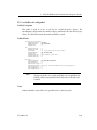
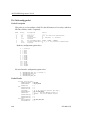
3.2 Example ADCCP NRM Call Sequences
Table 3–2 shows the sequence of DLI function calls to send and receive data using
blocking I/O. Table 3–3 is the non-blocking I/O example. The remainder of this chapter
and the Freeway Data Link Interface Reference Guide give further information about
each function call.
Note
The example call sequences assume that the cfgLink and enable DLI
configuration parameters are both set to “yes” (the defaults). This
means that dlOpen configures and enables the ICP links.
Figure 5–2 on page 105 shows an example DLI configuration file.
Table 3–2: DLI Call Sequence for ADCCP NRM (Blocking I/O)
1. Call dlInit to initialize the DLI environment.
The first parameter is your DLI binary configuration file name.
2. Call dlOpen for each required session (link) to get a session ID.
3. Call dlBufAlloc for all required input and output buffers.
4. Call dlWrite to send requests and data to Freeway.
5. Call dlRead to receive responses and data from Freeway.
6. Repeat Step 4 and Step 5 until you are finished writing and reading.
7. Call dlBufFree for all buffers allocated in Step 3.
8. Call dlClose for each session ID obtained in Step 2.
9. Call dlTerm to terminate your application’s access to Freeway.
DC 900-1317J
47
ADCCP NRM Programmer’s Guide
Note
When using non-blocking I/O, a dlRead request must always be
queued to avoid loss of data or responses from the ICP (see Step 5
of Table 3–3).
Table 3–3: DLI Call Sequence for ADCCP NRM (Non-blocking I/O)
1. Call dlInit to initialize the DLI environment.
The first parameter is your DLI binary configuration file name.
2. Call dlOpen for each required session (link) to get a session ID.
3. Call dlPoll to confirm the success of each session ID obtained in Step 2.
4. Call dlBufAlloc for all required input and output buffers.
5. Call dlRead to queue the initial read request.
6. Call dlWrite to send requests and data to Freeway.
7. Call dlRead to queue reads to receive responses and data from Freeway.
8. As I/Os complete and the I/O completion handler is invoked, call dlPoll to confirm the
success of each dlWrite in Step 6 and to accept the data from each dlRead in Step 7.
9. Repeat Step 6 through Step 8 until you are finished writing and reading.
10. Call dlBufFree for all buffers allocated in Step 4.
11. Call dlClose for each session ID obtained in Step 2.
12. Call dlPoll to confirm that each session was closed in Step 11.
13. Call dlTerm to terminate your application’s access to Freeway.
48
DC 900-1317J
3: ADCCP NRM DLI Functions
3.3 Overview of DLI Functions for ADCCP NRM
This section summarizes the DLI functions used in writing a client application. An
overview of using the DLI functions is:
•
Start up communications (dlInit, dlOpen, dlBufAlloc)
•
Send requests and data using dlWrite
•
Receive responses using dlRead
•
For blocking I/O, use dlSyncSelect to query read availability status for multiple
sessions
•
For non-blocking I/O, handle I/O completions at the software interrupt level in
the completion handler established by the dlInit or dlOpen function, or by periodic
use of dlPoll to query the I/O completion status
•
Monitor errors using dlpErrString
•
If necessary, reset and download the protocol software to the ICP using dlControl
•
Shut down communications (dlBufFree, dlClose, dlTerm)
Table 3–4 summarizes the DLI function syntax and parameters, listed in the most likely
calling order. Refer to the Freeway Data Link Interface Reference Guide for details.
Caution
DC 900-1317J
When using non-blocking I/O, there must always be at least one
dlRead request queued to avoid loss of data or responses from the
ICP.
49
ADCCP NRM Programmer’s Guide
Table 3–4: DLI Functions: Syntax and Parameters (Listed in Typical Call Order)
DLI Function
Parameter(s)
Parameter Usage
int dlInit
(char *cfgFile,
char *pUsrCb,
int (*fUsrIOCH)(char *pUsrCb));
DLI binary configuration file name
Optional I/O complete control block
Optional IOCH and parameter
int dlOpena
(char *cSessionName,
int (*fUsrIOCH)
(char *pUsrCB, int iSessionID));
Session name in DLI config file
Optional I/O completion handler
Parameters for IOCH
int dlPoll
(int iSessionID,
int iPollType,
char **ppBuf,
int *piBufLen,
char *pStat,
DLI_OPT_ARGS **ppOptArgs);
Session ID from dlOpen
Request type
Poll type dependent buffer
Size of I/O buffer (bytes)
Status or configuration buffer
Optional arguments
int dlpErrString
(int dlErrNo);
DLI error number (global variable
dlerrno)
char *dlBufAlloc
(int iBufLen);
Minimum buffer size
int dlRead
(int iSessionID,
char **ppBuf,
int iBufLen,
DLI_OPT_ARGS *pOptArgs);
Session ID from dlOpen
Buffer to receive data
Maximum bytes to be returned
Optional arguments structure
int dlWrite
(int iSessionID,
char *pBuf,
int iBufLen,
int iWritePriority,
DLI_OPT_ARGS *pOptArgs);
Session ID from dlOpen
Source buffer for write
Number of bytes to write
Write priority (normal or expedite)
Optional arguments structure
int dlSyncSelect
(int iNbrSessID,
int sessIDArray[],
int readStatArray[]);
Number of session IDs
Packed array of session IDs
Array containing read status for IDs
char *dlBufFree
(char *pBuf);
Buffer to return to pool
int dlClose
(int iSessionID,
int iCloseMode);
Session ID from dlOpen
Mode (normal or force)
int dlTerm
(void);
int dlControl
(char *cSessionName,
int iCommand,
int (*fUsrIOCH)
(char *pUsrCB, int iSessionID));
Session name in DLI config file
Command (e.g. reset/download)
Optional I/O completion handler
Parameters for IOCH
a
It is critical for the client application to receive the dlOpen completion status before making any other DLI
requests; otherwise, subsequent requests will fail.
50
DC 900-1317J
3: ADCCP NRM DLI Functions
3.3.1 DLI Optional Arguments
The dlWrite and dlRead functions handle the control packets for an ADCCP NRM application. Both functions can use the optional arguments parameter to provide the protocol-specific information required for Raw operation (Section 3.1.2). The “C” definition
of the optional arguments structure is shown in Figure 3–1.
typedef struct
{
unsigned short
unsigned short
}
unsigned
unsigned
unsigned
unsigned
short
unsigned
short
short
short
short
unsigned
short
unsigned
unsigned
unsigned
short
short
short
short
short
unsigned short
unsigned short
DLI_OPT_ARGS;
_DLI_OPT_ARGS
usFWPacketType;
usFWCommand;
usFWStatus;
usICPClientID;
usICPServerID;
usICPCommand;
iICPStatus;
usICPParms[3];
usProtCommand;
iProtModifier;
usProtLinkID;
usProtCircuitID;
usProtSessionID;
usProtSequence;
usProtXParms[2];
/*
/*
/*
/*
/*
/*
/*
/*
/*
/*
/*
/*
/*
/*
/*
/*
/*
/*
FW_CONTROL or FW_DATA
FW_ICP_WRITE, FW_ICP_WRITE_EXP
or FW_ICP_READ
0
0
0
DLI_ICP_CMD_READ/DLI_ICP_CMD_WRITE
ICP return error code (dlRead)
usICPParms[1] = DLI session ID
(returned by dlOpen
)
Required field (see Table 3–5)
Required field (see Table 3–5)
Required field (see Section 3.4)
0
ICP session ID (returned in
DLI_ICP_CMD_ATTACH response)
0
Station ID and data size
*/
*/
*/
*/
*/
*/
*/
*/
*/
*/
*/
*/
*/
*/
*/
*/
*/
*/
Figure 3–1: “C” Definition of DLI Optional Arguments Structure
Note
DC 900-1317J
If the protocol DLI configuration parameter is specified as “raw,” all
the optional arguments shown in the C-style structure definition
on page 51 must be specified when the optional arguments are
included in a dlWrite call. If the protocol parameter is specified as
“ADCCPNRM” but the optional arguments are included in a
dlWrite call, only usFWPacketType, usFWCommand, usICPCommand,
usProtCommand, iProtModifier, usProtCircuitID, and both usProtXParms must be specified.
51
ADCCP NRM Programmer’s Guide
3.4 Client/ICP Control Packet Formats
The ADCCP NRM protocol software running on an ICP is controlled by a set of control
packets sent by the DLI or by the client application using Raw dlWrite and dlRead
requests. This section describes all control packets in detail and lists the optional arguments fields required by each packet.
Note
The use of Normal dlRead requests (that is, without the optional
arguments parameter) is not recommended for ADCCP NRM
since error reports would be indistinguishable from data received
from the remote application.
Table 3–5 shows the dlWrite usProtCommand and iProtModifier fields for packets sent to
the ICP. Table 3–6 shows the same information for packets received from the ICP using
dlRead.
The dlWrite usProtLinkID field is optional in most control packets; however, under some
conditions, the client must specify this field. This occurs when the client:
52
•
sets a multipoint list
•
enables a physical link
•
disables a physical link
•
reconfigures a link or configures a station on a link
•
requests link statistics
•
signals an idle link
•
sends data via selective or global broadcast
DC 900-1317J
3: ADCCP NRM DLI Functions
Table 3–5: Client Packet dlWrite usProtCommand and iProtModifier Fields
dlWrite usProtCommand Field
DLI_PROT_SEND_STATION_INIT
dlWrite iProtModifier Field
0 = remote (SIM/RIM on line)
1 = local (no SIM/RIM)
Reference Section
Section 3.4.1 on page 55
DLI_PROT_SEND_UNFORMATTED_DATA
Section 3.4.3 on page 57
DLI_PROT_SEND_UNFORMATTED_DATA_EOM
Section 3.4.5 on page 58
DLI_PROT_SEND_EXCHANGE_ID
Section 3.4.6 on page 58
DLI_PROT_SEND_NORM_DATA
Bit 0
0 = Final Frame
1 = More Data Follows
Bits 1 and 2: NRM Primary only
0 = Normal Addressing
1 = Selective Broadcast
2 = General Broadcast
Bits 3–7: Reserved
Section 3.4.8 on page 59
DLI_PROT_SEND_UNNUMBERED_DATA
Bit 0
0 = Final Frame
1 = More Data Follows
Bits 1 and 2: NRM Primary only
0 = Normal Addressing
1 = Selective Broadcast
2 = General Broadcast
Bits 3–7: Reserved
Section 3.4.10 on page 62
DLI_PROT_SEND_UNNUMBERED_DATA_EOM
Section 3.4.12 on page 64
DLI_PROT_SEND_SET_MULTIPNT_LIST
Section 3.4.13 on page 64
DLI_PROT_SEND_BIND
Time limit
0 = No Limit
1–255 = Limit in seconds
DLI_PROT_SEND_UNBIND
DLI_PROT_CFG_LINK
Section 3.4.16 on page 67
Section 3.4.18 on page 68
–1 = Adjust station timers
0 = Reconfigure Link
1 = Configure NRM/NRME station
Section 3.4.20 on page 69
DLI_PROT_SEND_STATION_RESET
Section 3.4.22 on page 77
DLI_PROT_SEND_STATION_RESET_CFM
Section 3.4.24 on page 78
DLI_PROT_GET_STATISTICS_REPORT
Section 3.4.26 on page 79
DLI_PROT_GET_BUF_REPORT
DLI_PROT_SET_BUF_SIZE
DLI_PROT_GET_SOFTWARE_VER
DC 900-1317J
Section 3.4.29 on page 81
Number of 64-byte pages
Section 3.4.31 on page 81
Section 3.4.33 on page 82
53
ADCCP NRM Programmer’s Guide
Table 3–6: ICP Packet dlRead usProtCommand and iProtModifier Fields
dlRead usProtCommand Field
dlRead iProtModifier Field
Reference Section
DLI_PROT_RECV_STATION_INIT
0 = remote (SIM/RIM on line)
1 = local (no SIM/RIM)
Section 3.4.2 on page 56
DLI_PROT_RECV_UNFORMATTED_DATA
Bit 0–6: Reserved
Bit 7: Error indication
Section 3.4.4 on page 58
DLI_PROT_RECV_EXCHANGE_ID
Section 3.4.7 on page 59
DLI_PROT_RECV_DATA
Bit 0: Reserved
Bits 1 and 2: NRM Secondary only
0 = Normal Addressing
1 = Selective Broadcast
2 = General Broadcast
Bits 3–7: Reserved
Section 3.4.9 on page 61
DLI_PROT_RECV_UNNUMBERED_DATA
Bit 0: Reserved
Bits 1 and 2: NRM Secondary only
0 = Normal Addressing
1 = Selective Broadcast
2 = General Broadcast
Bits 3–6: Reserved
Bit 7: Error indication
Section 3.4.11 on page 63
DLI_PROT_RESP_LOCAL_ACK
Type of packet being ACKed
Section 3.4.14 on page 65
DLI_PROT_RESP_NORMAL_ACK
Number of packets ACKed
Section 3.4.15 on page 66
DLI_PROT_RESP_BIND_ACK
Station mode
1 = NRM
Section 3.4.17 on page 67
4 = NRME
DLI_PROT_RESP_UNBIND_ACK
DLI_PROT_RECV_STATION_RESET
DLI_PROT_RECV_STATION_RESET_CFM
DLI_PROT_RECV_LINK_EXCEPTION
Section 3.4.19 on page 69
Station mode
1 = NRM
4 = NRME
Section 3.4.21 on page 77
Station mode
1 = NRM
4 = NRME
Section 3.4.23 on page 78
1 = Data Poll Timeout
2 = Data Poll Resumed
3 = Retry Limit Exceeded
4 = Flags Synch. Lost
7 = DCD Lost
8 = DCD Gained
DLI_PROT_RECV_STATISTICS_REPORT
Section 3.4.25 on page 78
Section 3.4.27 on page 79
DLI_PROT_RESP_ERROR
Rejected command type
Section 3.4.28 on page 80
DLI_PROT_RESP_BUF_REPORT
0
Section 3.4.30 on page 81
DLI_PROT_RECV_BUF_SIZE
Section 3.4.32 on page 82
DLI_PROT_RECV_SOFTWARE_VER
Section 3.4.34 on page 82
54
DC 900-1317J
3: ADCCP NRM DLI Functions
The usProtXParms[0] field is used to specify the station ID. The station ID field is specified in most control packets. However, under some conditions, the client must specify
station number zero. This occurs when the client:
•
enables a physical link
•
disables a physical link
•
reconfigures a link
•
requests link statistics
•
signals an idle link
•
sets the maximum data size
•
requests software version data
The usProtXParms[1] field is the data size, which specifies the number of bytes actually
used in the transparent data area. The data size may be any value from zero up to and
including the maximum allowable data size (see Section 4.1.1 on page 85).
The transparent data area, if present, contains additional information required to complete the control packet. Data area contents are discussed in Section 3.4.1 through
Section 3.4.34.
3.4.1 DLI_PROT_SEND_STATION_INIT Packet
This packet is valid only if the client has enabled ADCCP option 5 (see Section 3.4.20.2)
for the specified station. The client must specify the usProtCommand field
(DLI_PROT_SEND_STATION_INIT), the usProtXParms[0] field (station ID), and the
iProtModifier field.
DC 900-1317J
55
ADCCP NRM Programmer’s Guide
The client uses this packet to change station operation to the initialization state. The
iProtModifier field indicates whether the initialization involves only the local station or
the remote station as well.
When the ICP receives a DLI_PROT_SEND_STATION_INIT packet with zero in the iProtModifier
field, the ICP initiates an SIM/UA or RIM/SIM/UA exchange on the link for the specified station. This ensures that the remote station is also placed in initialization mode.
When the link-level exchange is complete, the ICP sends to the client a
DLI_PROT_RECV_STATION_INIT packet with zero in the iProtModifier field.
When the ICP receives a DLI_PROT_SEND_STATION_INIT packet with one in the iProtModifier
field, the ICP immediately changes the indicated station to the initialization mode and
sends to the client a DLI_PROT_RECV_STATION_INIT packet with one in the iProtModifier field.
In this case, only the local station is placed in the initialization mode; the change is
transparent to the remote station.
The ANSI ADCCP specification does not clearly define the initialization state, but indicates that it may be used to download data (or code) to (or from) a remote station.
While in this state, the client station may send DLI_PROT_SEND_UNFORMATTED_DATA packets
and may receive DLI_PROT_RECV_UNFORMATTED_DATA packets. The ICP transmits and
receives unformatted data as raw information bounded by flags and terminated with a
frame check sequence (FCS) field. The client adopts total responsibility for defining and
adhering to the link-level protocol used in initialization state operation.
3.4.2 DLI_PROT_RECV_STATION_INIT Packet
This packet is valid only if the client has enabled ADCCP option 5 (see Section 3.4.20.2)
for
the
specified
station.
The
ICP
specifies
the
usProtCommand
field
(DLI_PROT_RECV_STATION_INIT), the link ID, and the usProtXParms[0] field (station ID). The
iProtModifier field indicates whether the initialization involves only the local station or
the remote station as well. The usProtXParms[1] field (data size) is zeroed.
56
DC 900-1317J
3: ADCCP NRM DLI Functions
The ICP sends to the client a DLI_PROT_RECV_STATION_INIT packet with zero in the
iProtModifier field following detection of a completed SIM/UA or RIM/SIM/UA
exchange on the link. This indicates that both the local and remote stations are in initialization mode.
The ICP sends to the client a DLI_PROT_RECV_STATION_INIT packet with one in the
iProtModifier field following receipt of a DLI_PROT_SEND_STATION_INIT packet with one in
the iProtModifier field. In this case, only the local station is placed in the initialization
mode; the change is transparent to the remote station.
The client may receive this packet as a response to sending a DLI_PROT_SEND_STATION_INIT
packet to the ICP or as an unsolicited ICP packet. In either case, the client does not
respond to the ICP packet, but immediately places the indicated station in the initialization state. Once again, the client adopts total responsibility for defining and adhering to
the link-level protocol used in initialization state operation (see Section 3.4.1).
3.4.3 DLI_PROT_SEND_UNFORMATTED_DATA Packet
This packet is valid only if the client has enabled ADCCP option 5 (see Section 3.4.20.2)
for the specified station and the station is in the initialization state. The client must
specify
the
usProtCommand
field
(DLI_PROT_SEND_UNFORMATTED_DATA),
the
usProtXParms[0] field (station ID), the usProtXParms[1] field (data size), and the data
field contents. The ICP transmits the contents of the data field with a trailing frame
check sequence (FCS). The client has total responsibility for handling all initialization
protocol requirements.
The ADCCP protocol does not define data flow control for unformatted frames. Therefore,
the
client
is
responsible
DLI_PROT_RECV_UNFORMATTED_DATA
for
not
swamping
the
ICP
with
packets. If the client does overload the ICP, the ICP
simply stops accepting input from the client; the client cannot send additional control
packets to the ICP until the ICP’s buffer congestion clears. If buffer congestion occurs
DC 900-1317J
57
ADCCP NRM Programmer’s Guide
on the ICP, an application in the client attempting to write a control packet to the ICP
experiences delayed I/O completion, but no packet is actually lost.
3.4.4 DLI_PROT_RECV_UNFORMATTED_DATA Packet
This packet is valid only if the client has enabled ADCCP option 5 (see Section 3.4.20.2)
for the specified station and the station is in the initialization state. The ICP specifies the
usProtCommand
field
(DLI_PROT_RECV_UNFORMATTED_DATA),
the
link
ID,
the
usProtXParms[0] field (station ID), the usProtXParms[1] field (data size), and the data
field contents. The client has total responsibility for handling all initialization protocol
requirements.
For all stations, bit 7 in the iProtModifier field is an error indicator. Bit 7 is set to one if
the ICP detected an error during reception of the frame associated with the
DLI_PROT_RECV_UNFORMATTED_DATA packet passed to
the client. If bit 7 is reset to zero, no
error was detected.
3.4.5 DLI_PROT_SEND_UNFORMATTED_DATA_EOM Packet
As an option, the client may send the DLI_PROT_SEND_UNFORMATTED_DATA_EOM packet
instead of the similarly named DLI_PROT_SEND_UNFORMATTED_DATA packet to request that
the ICP respond with a corresponding DLI_PROT_RESP_LOCAL_ACK response packet to
report transmission completion status. This packet is valid only if the client has enabled
ADCCP option 5 (see Section 3.4.20.2).
Note that if the optional arguments in the DLI_PROT_SEND_UNFORMATTED_DATA_EOM packet
specify a link or station that is not configured or not online at the time of the request,
the ICP replies instead with a DLI_PROT_RESP_ERROR packet.
3.4.6 DLI_PROT_SEND_EXCHANGE_ID Packet
This packet is valid only if the client has enabled ADCCP option 1 (see Section 3.4.20.2)
for the specified station and the station is not in the initialization state. The client must
58
DC 900-1317J
3: ADCCP NRM DLI Functions
specify the usProtCommand field (DLI_PROT_SEND_EXCHANGE_ID), the usProtXParms[0] field
(station ID), the usProtXParms[1] field (data size), and the data field contents. The data
size may be zero because the data field is optional.
The client sends an Exchange ID packet either to initiate an exchange of station identification on the link or to respond to a DLI_PROT_RECV_EXCHANGE_ID packet (see
Section 3.4.7). The client initiates an ID exchange at a primary station and replies at a
secondary station. Exchange of station identification consists of the exchange of an XID
command and XID response on the link. When the client initiates the ID exchange, the
ICP replies with a DLI_PROT_RECV_EXCHANGE_ID packet containing the remote station’s
identification. When the ICP initiates the exchange of ID, the client replies with a
DLI_PROT_SEND_EXCHANGE_ID packet containing the local station’s identification.
3.4.7 DLI_PROT_RECV_EXCHANGE_ID Packet
This packet is valid only if the client has enabled ADCCP option 1 (see Section 3.4.20.2)
for the specified station and the station is not in the initialization state. The ICP specifies the usProtCommand field (DLI_PROT_RECV_EXCHANGE_ID), the link ID, the
usProtXParms[0] field (station ID), the usProtXParms[1] field (data size), and the data
field contents. The iProtModifier field is zeroed and, because the data field is optional,
the data size may be zero.
The client may receive this packet either as a response to sending a
DLI_PROT_SEND_EXCHANGE_ID
packet (see Section 3.4.6) to the ICP or as an unsolicited
ICP packet. When the client initiates the ID exchange, the ICP replies with a
DLI_PROT_RECV_EXCHANGE_ID packet containing the remote station’s identification. When
the ICP initiates the exchange of ID, the client replies with a DLI_PROT_SEND_EXCHANGE_ID
packet containing the local station’s identification.
3.4.8 DLI_PROT_SEND_NORM_DATA Packet
This packet is valid for primary stations unless the client has enabled ADCCP option 9
(see Section 3.4.20.2) for the specified primary station. The packet is valid for secondary
DC 900-1317J
59
ADCCP NRM Programmer’s Guide
stations unless the client has enabled ADCCP option 8 for the specified secondary station. The client must specify the usProtCommand field (DLI_PROT_SEND_NORM_DATA), the
iProtModifier field, the usProtXParms[0] field (station ID), the usProtXParms[1] field (data
size), and the data field contents.
For NRM primary and secondary stations, bit 0 in the iProtModifier field indicates
whether more data follows. The client should use the more data indication if one of the
following conditions applies:
•
The client sends numerous DLI_PROT_SEND_NORM_DATA packets via an NRM primary station using selective or global broadcast addressing and wants to use RNR
polling instead of RR polling to inhibit secondary response I-frame transmissions
during the broadcast
•
The client wants to send as much data as possible in each poll response via an
NRM secondary station.
When bit 0 in the iProtModifier field is reset to zero, the ICP assumes that the data packet
is the final frame in a data set. If the data packet is sent via an NRM primary station, the
ICP enables normal polling. If the data packet is sent via an NRM secondary station, the
ICP transmits the data in an I-frame with the F-bit set to one.
When bit 0 in the iProtModifier field is set to one, the ICP assumes that more data packets follow. If the data packet is sent as part of an NRM primary station broadcast, the
ICP switches to RNR polling (to inhibit secondary response I-frame transmission) and
allows the client one to two seconds after broadcast completion to send more data
before reverting to normal (RR) polling automatically. If the data packet is sent via an
NRM secondary station and the station’s transmit window is still open, the ICP transmits the data in a response I-frame with the F-bit reset to zero.
For NRM primary stations, bits 1 and 2 in the iProtModifier field indicate the frame
addressing mode requested by the client. If both bits 1 and 2 are reset to zero, the ICP
uses normal individual station addressing. If bit 1 is set to one and bit 2 is reset to zero,
60
DC 900-1317J
3: ADCCP NRM DLI Functions
the ICP uses selective broadcast addressing. If bit 1 is reset to zero and bit 2 is set to one,
the ICP uses general broadcast addressing. If both bits 1 and 2 are set to one, the ICP
returns a DLI_PROT_RESP_ERROR packet to the client.
When selective or global addressing is used, the client must specify the link ID and zero
the station ID, since the data is intended for multiple stations on the link. Prior to using
the selective broadcast addressing mode, the client must set the multipoint list (see
Section 3.4.13).
The ADCCP protocol defines a flow control procedure for I-frames. In the client/ICP
interface, flow control is implemented for DLI_PROT_SEND_NORM_DATA packets. The client
may send several DLI_PROT_SEND_NORM_DATA packets to the ICP while awaiting acknowledgment in the form of DLI_PROT_RESP_NORMAL_ACK packets.
The client must limit the total number of unacknowledged DLI_PROT_SEND_NORM_DATA
packets to avoid causing buffer congestion on the ICP. If the client overloads the ICP,
the ICP simply stops accepting input from the client; the client cannot send additional
control packets to the ICP until the ICP’s buffer congestion clears. If buffer congestion
occurs on the ICP, an application in the client attempting to write a control packet to
the ICP experiences delayed I/O completion, but no packet is actually lost.
3.4.9 DLI_PROT_RECV_DATA Packet
This packet is valid for primary stations unless the client has enabled ADCCP option 8
(see Section 3.4.20.2) for the specified primary station. The packet is valid for secondary
stations unless the client has enabled ADCCP option 9 for the specified secondary station. The ICP specifies the usProtCommand field (DLI_PROT_RECV_DATA), the iProtModifier
field, the link ID, the usProtXParms[0] field (station ID), the usProtXParms[1] field (data
size), and the data field contents.
For NRM secondary stations, bits 1 and 2 in the iProtModifier field indicate the addressing mode in the received frame. If both bits 1 and 2 are reset to zero, normal individual
station addressing is indicated. If bit 1 is set to one and bit 2 is reset to zero, selective
DC 900-1317J
61
ADCCP NRM Programmer’s Guide
broadcast addressing is indicated. If bit 1 is reset to zero and bit 2 is set to one, general
broadcast addressing is indicated. Bit 0 and bits 3 through 7 in the iProtModifier field are
zeroed.
3.4.10 DLI_PROT_SEND_UNNUMBERED_DATA Packet
This packet is valid only if the client has enabled ADCCP option 4 (see Section 3.4.20.2)
for the specified station. The client must specify the usProtCommand field
(DLI_PROT_SEND_UNNUMBERED_DATA), the iProtModifier field, the usProtXParms[0] field (station ID), the usProtXParms[1] field (data size), and the data field contents.
For NRM stations, bit 0 in the iProtModifier field indicates whether more data follows.
The client should use the more data indication if one of the following conditions
applies:
•
The client sends numerous Unnumbered Data packets via an NRM primary station using selective or global broadcast addressing and wants to use RNR polling
instead of RR polling to inhibit secondary response I-frame transmissions during
the broadcast
•
The client wants to send as much data as possible in each poll response via an
NRM secondary station
When bit 0 in the iProtModifier field is reset to zero, the ICP assumes that the data packet
is the final frame in a data set. If the data packet is sent via an NRM primary station, the
ICP enables normal polling. If the data packet is sent via an NRM secondary station, the
ICP transmits the data in an I-frame with the F-bit set to one.
When bit 0 in the iProtModifier field is set to one, the ICP assumes that more data packets follow. If the data packet is sent as part of an NRM primary station broadcast, the
ICP switches to RNR polling (to inhibit secondary response I-frame transmission) and
allows the client one to two seconds after broadcast completion to send more data
before reverting to normal (RR) polling automatically. If the data packet is sent via an
62
DC 900-1317J
3: ADCCP NRM DLI Functions
NRM secondary station and the station’s transmit window is still open, the ICP transmits the data in a response I-frame with the F-bit reset to zero.
For NRM primary stations, bits 1 and 2 in the iProtModifier field indicate the frame
addressing mode requested by the client. If both bits 1 and 2 are reset to zero, the ICP
uses normal individual station addressing. If bit 1 is set to one and bit 2 is reset to zero,
the ICP uses selective broadcast addressing. If bit 1 is reset to zero and bit 2 is set to one,
the ICP uses general broadcast addressing. If both bits 1 and 2 are set to one, the ICP
returns a DLI_PROT_RESP_ERROR packet to the client.
When selective or global addressing is used, the client must specify the link ID and zero
the station ID, since the data is intended for multiple stations on the link. Prior to using
the selective broadcast addressing mode, the client must set the multipoint list (see
Section 3.4.13).
The ADCCP protocol does not define data flow control for unnumbered information
frames. Therefore, the client is responsible for not swamping the ICP with
DLI_PROT_SEND_UNNUMBERED_DATA
packets. If the client does overload the ICP, the ICP
simply stops accepting input from the client; the client cannot send additional control
packets to the ICP until the ICP’s buffer congestion clears. If buffer congestion occurs
on the ICP, an application in the client attempting to write a control packet to the ICP
experiences delayed I/O completion, but no packet is actually lost.
3.4.11 DLI_PROT_RECV_UNNUMBERED_DATA Packet
This packet is valid only if the client has enabled ADCCP option 4 (see Section 3.4.20.2)
for
the
specified
station.
The
(DLI_PROT_RECV_UNNUMBERED_DATA),
ICP
the
specifies
iProtModifier
the
field,
usProtCommand
the
link
ID,
field
the
usProtXParms[0] field (station ID), the usProtXParms[1] field (data size), and the data
field contents.
For NRM secondary stations, bits 1 and 2 in the iProtModifier field indicate the frame
addressing mode used. If both bits 1 and 2 are reset to zero, normal individual station
DC 900-1317J
63
ADCCP NRM Programmer’s Guide
addressing is indicated. If bit 1 is set to one and bit 2 is reset to zero, selective broadcast
addressing is indicated. If bit 1 is reset to zero and bit 2 is set to one, general broadcast
addressing is indicated.
For all stations, bit 7 in the iProtModifier field is an error indicator. Bit 7 is set to one if
the ICP detected an error during reception of the UI frame associated with the
DLI_PROT_RECV_UNNUMBERED_DATA
packet passed to the client. If bit 7 is reset to zero, no
error was detected. Bit 0 and bits 3 through 6 in the iProtModifier field are zeroed.
3.4.12 DLI_PROT_SEND_UNNUMBERED_DATA_EOM Packet
As an option, the client can send the DLI_PROT_SEND_UNNUMBERED_DATA_EOM packet
instead of the similarly named DLI_PROT_SEND_UNNUMBERED_DATA packet to request that
the ICP respond with a corresponding DLI_PROT_RESP_LOCAL_ACK response packet to
report transmission completion status. This packet is valid only if the client has enabled
ADCCP option 4 (see Section 3.4.20.2 on page 71).
Note that if the optional arguments in the DLI_PROT_SEND_UNNUMBERED_DATA_EOM packet
specify a link or station that is not configured or not online at the time of the request,
the ICP replies instead with a DLI_PROT_RESP_ERROR packet.
3.4.13 DLI_PROT_SEND_SET_MULTIPNT_LIST Packet
This packet is valid only if the client has enabled ADCCP option 7 (see Section 3.4.20.2)
for the specified station operating in NRM mode and has configured each local or
remote secondary station address as a single octet. This packet is valid both in the disconnected state and in the information transfer state.
When extended addressing (ADCCP option 7) is enabled, a frame containing a multiple octet address field may address either a single station or a list of stations. On a given
link, the client controls which interpretation is used by identifying stations that use the
second concept to implement a multipoint selective broadcast function. The
DLI_PROT_SEND_SET_MULTIPNT_LIST packet is used for this purpose.
64
DC 900-1317J
3: ADCCP NRM DLI Functions
The client specifies the usProtCommand field (DLI_PROT_SEND_SET_MULTIPNT_LIST), the link
ID, the usProtXParms[1] field (data size), and the data field contents. The data field contains a list of secondary stations (specified by station ID) on the indicated link that support the multipoint (selective broadcast) addressing concept.
The client uses the DLI_PROT_SEND_SET_MULTIPNT_LIST packet to identify two types of secondary stations:
•
Local secondary stations on a link that are required to recognize selective broadcast frames addressed to them
•
Remote secondary stations to be addressed when the primary sends data with
selective broadcast addressing
All stations specified must be on the same physical link, and no more than 32 stations
per physical link can support multipoint addressing at one time. If multipoint addressing is required on more than one link, the client sends a separate control packet for each
physical link.
Each time the client sets the multipoint list for a physical link, any previous multipoint
station list is deleted. The client may suppress multipoint addressing for all stations on
a physical link by sending this packet with the usProtXParms[1] field (data size) set to
zero and no stations listed.
3.4.14 DLI_PROT_RESP_LOCAL_ACK Packet
This packet is valid only if the client has enabled ADCCP option 4 or 5 (see
Section 3.4.20.2 on page 71). In the DLI_PROT_RESP_LOCAL_ACK packet optional arguments, the iICPStatus field reports a transmission status code, and the iProtModifier field
reports the type of packet being acknowledged.
Transmission status codes that can appear in the iICPStatus field are listed below. See
Table B–1 on page 120 for error descriptions.
DC 900-1317J
65
ADCCP NRM Programmer’s Guide
•
DLI_ICP_ERR_NO_ERR
•
DLI_ICP_ERR_XMIT_ABORTED
•
DLI_ICP_ERR_XMIT_TIMEOUT
Packet type identifier codes that can appear in the iProtModifier field are:
•
DLI_PROT_SEND_UNFORMATTED_DATA_EOM
•
DLI_PROT_SEND_UNNUMBERED_DATA_EOM
3.4.15 DLI_PROT_RESP_NORMAL_ACK Packet
The
concept
of
a
transmit
window
(which
limits
the
number
of
DLI_PROT_SEND_NORM_DATA packets the client may send while awaiting acknowledgment)
applies to each individual station. The ICP uses the DLI_PROT_RESP_NORMAL_ACK packet to
acknowledge one or more previously sent DLI_PROT_SEND_NORM_DATA packets for a specified station. The client views this as authorization to send a specified number of additional DLI_PROT_SEND_NORM_DATA packets for the indicated station.
When the client sends DLI_PROT_SEND_NORM_DATA packets with either selective (multipoint) or global addressing indicated to broadcast data to remote NRM secondary stations, the ICP returns DLI_PROT_RESP_NORMAL_ACK packets for each responding NRM
secondary station on the physical link. This lets the client determine which NRM secondary stations received the broadcast.
The ICP specifies the usProtCommand field (DLI_PROT_RESP_NORMAL_ACK), the
iProtModifier field, the link ID, and the usProtXParms[0] field (station ID). The
iProtModifier field gives the number of DLI_PROT_SEND_NORM_DATA packets acknowledged
(that is, the number of additional DLI_PROT_SEND_NORM_DATA packets the client may
send).
66
DC 900-1317J
3: ADCCP NRM DLI Functions
3.4.16 DLI_PROT_SEND_BIND Packet
The client uses this packet to enable a physical link or to enable a station. When the ICP
is initially downloaded, all physical links are disabled. After the client configures links
and stations (see Section 4.1.2 on page 86), the client must enable a physical link prior
to enabling stations on the link.
To enable a physical link, the client must specify the usProtCommand field
(DLI_PROT_SEND_BIND), the link ID, and a zeroed usProtXParms[0] field (station ID). The
presence of the zeroed station ID tells the ICP that the control packet relates to the
physical link, rather than to an assigned station.
To enable an assigned station on a link, the client must specify the usProtCommand field
(DLI_PROT_SEND_BIND), the iProtModifier field, and the usProtXParms[0] field (station ID).
The presence of the station ID tells the ICP that the control packet relates to an assigned
station, rather than to the physical link. The iProtModifier field specifies a time limit on
the request to enable the station. A zero in the iProtModifier field specifies an infinite
time limit. A non-zero iProtModifier field gives the time limit in seconds. When this
limit is exceeded, the ICP notifies the client with an ICP Station Inactive packet.
The ICP’s normal response to the DLI_PROT_SEND_BIND packet is a DLI_PROT_RESP_BIND_ACK
packet. However, if the client attempts to enable an active link or station, the ICP
returns a DLI_PROT_RESP_ERROR packet.
3.4.17 DLI_PROT_RESP_BIND_ACK Packet
The ICP uses this packet to report a physical link active or a station active on the link.
The ICP reports a physical link active only when it changes from an inactive state to an
active state. The ICP reports a station active when it changes from either a disconnected
state or an initialization state to an information transfer state.
When reporting an active physical link, the ICP specifies the usProtCommand field
(DLI_PROT_RESP_BIND_ACK), the link ID, and a zeroed usProtXParms[0] field (station ID).
DC 900-1317J
67
ADCCP NRM Programmer’s Guide
The presence of the zeroed station ID tells the client that the control packet relates to
the physical link, rather than to an assigned station.
When reporting an active station on a link, the ICP specifies the usProtCommand field
(DLI_PROT_RESP_BIND_ACK), the iProtModifier field, the link ID, and the usProtXParms[0]
field (station ID). The iProtModifier field indicates the station’s operational mode (see
Table 3–6). The presence of the station ID tells the client that the control packet relates
to an assigned station, rather than to the physical link.
3.4.18 DLI_PROT_SEND_UNBIND Packet
The client uses this packet to disable a physical link or an active station on the link. If
the client attempts to disable the physical link while at least one station is active on the
link, the ICP disables all active stations on the link prior to disabling the physical link.
To disable a physical link, the client must specify the usProtCommand field
(DLI_PROT_SEND_UNBIND), the link ID, and a zeroed usProtXParms[0] field (station ID).
The presence of the zeroed station ID tells the ICP that the control packet relates to the
physical link, rather than to an assigned station.
To disable an assigned station on a link, the client must specify the usProtCommand field
(DLI_PROT_SEND_UNBIND) and the usProtXParms[0] field (station ID). The presence of the
station ID tells the ICP that the control packet relates to an assigned station, rather than
to the physical link.
The
ICP’s
normal
response
DLI_PROT_RESP_UNBIND_ACK
to
the
DLI_PROT_SEND_UNBIND
packet
is
a
packet. If the client attempts to disable an inactive link, the
ICP sends the normal response (DLI_PROT_RESP_UNBIND_ACK). However, if the client
attempts to disable an inactive station, the ICP returns a DLI_PROT_RESP_ERROR packet.
A call to dlClose (described in the Freeway Data Link Interface Reference Guide) also
stops the link, but terminates the session as well. This is the normal method to terminate a session at the end of a client application. The DLI_PROT_SEND_UNBIND packet is use-
68
DC 900-1317J
3: ADCCP NRM DLI Functions
ful for temporarily stopping the link without terminating the session (for example, to
reconfigure the link using the DLI_PROT_CFG_LINK packet). The link is restarted by issuing
a DLI_PROT_SEND_BIND packet.
3.4.19 DLI_PROT_RESP_UNBIND_ACK Packet
The ICP uses this packet to report a physical link inactive or a station inactive on the
link. The ICP reports a physical link inactive after the client attempts to disable it; the
ICP’s response is the same regardless of whether the physical link was active or inactive
at the time of the client’s request. However, the ICP reports a station inactive only when
it changes from either an initialization state or an information transfer state to a disconnected state.
When reporting an inactive physical link, the ICP specifies the usProtCommand field
(DLI_PROT_RESP_UNBIND_ACK), the link ID, and a zeroed usProtXParms[0] field (station
ID). The presence of the zeroed station ID tells the client that the control packet relates
to the physical link, rather than to an assigned station.
When reporting an inactive station on a link, the ICP specifies the usProtCommand field
(DLI_PROT_RESP_UNBIND_ACK), the link ID, and the usProtXParms[0] field (station ID). The
presence of the station ID tells the client that the control packet relates to an assigned
station, rather than to the physical link.
3.4.20 DLI_PROT_CFG_LINK Packet
The client uses this packet to configure a link or a station or to adjust selected station
operation parameters. The DLI_PROT_CFG_LINK packet uses the data area to convey
parameter information beyond that given in the iProtModifier field. The usProtXParms[1]
field (data size) must correctly specify the size of this data area. Table 3–7, Figure 3–2,
and Table 3–8 show the required content of the data area for each of the three variants
of the DLI_PROT_CFG_LINK packet. See also Section 4.1.2 on page 86. If your application
must perform link configuration itself, you must set both the cfgLink and enable DLI
configuration parameters to “no” for that link (Section 5.2 on page 104).
DC 900-1317J
69
ADCCP NRM Programmer’s Guide
3.4.20.1 First Variant
The first variant of the DLI_PROT_CFG_LINK packet allows the client to configure a physical
link. The client must specify the usProtCommand field (DLI_PROT_CFG_LINK), iProtModifier
field (0,) the link ID, usProtXParms[1] field (data size = 2 or 4), and the data area (see
Table 3–7).
Bits 0–3 in word 0 of the data area select the nominal baud rate. The client must specify
the nominal baud rate even if the clock source is external. The ICP bases the default
retry timer values upon this nominal baud rate and the maximum data size.
Bits 4 and 5 of word 0 must be zero.
Bit 6 in word 0 selects the transmit clock source (receive clocking is always externally
derived). Internal or external transmit clocking may be selected. When the client selects
external, the nominal baud rate specification need not be precise if the client adjusts the
station timer constants to values known to be correct (see Section 3.4.20.3).
Bits 7–15 of word 0 must be zero.
The use of word 1 of the data area, which configures the data encoding and electrical
interface for the link, is optional. If word 1 is used, the data size must be four bytes. If
the data size is two bytes, then word 1 is not used, the link’s data encoding is defaulted
to NRZ, and its electrical interface is defaulted to EIA-232.
Bits 0-7 of word 1 select the data encoding for the link. NRZ, NRZI, or ANRZI may be
selected. ANRZI (“asynchronous NRZI”) is a special use of NRZI encoding wherein the
receive clock is extracted from the data signal (while the transmit clock source is internal). 115200 bits/second is the highest data rate offered with ANRZI encoding.)
Bits 8-11 of word 1 select the electrical interface. EIA-232, EIA-449, EIA-530, or V.35
may be selected.
Bits 12-15 of word 1, when it is used, must be zero.
70
DC 900-1317J
3: ADCCP NRM DLI Functions
Table 3–7: DLI_PROT_CFG_LINK Packet Data Area (First Variant)
First Variant:
Argument = 0
and
Station = 0
(Size = 2 or 4)
(Configures physical link)
Word 0: Link parameters
Bits 0–3: (Nominal baud rate in bits/second)
0 = reserved
1 = 1200
2 = 2400
3 = 4800
4 = 9600
5 = 19200
6 = 38400
7 = 56000
8 = 57600
9 = 64000
10 = 73728
11 = 76800
12 = 92160
13 = 115200
14 = 122880
Bits 4 and 5: must be zero
Bit 6: clock source: 0 = internal
1 = external
Bit 7–15: must be zero
Word 1: (optional)
Bits 0–7: Bit encoding format
0 = NRZ
1 = NRZI
2 = ANRZI
Bits 8–11: Electrical Interface:
0 = EIA-232
2 = EIA-530
3 = V.35
4 = EIA-449
Bits 12–15: must be zero
3.4.20.2 Second Variant
The second variant of the DLI_PROT_CFG_LINK packet allows the client to configure a station on a link. The client must specify the usProtCommand field (DLI_PROT_CFG_LINK),
the iProtModifier field, the link ID, a non-zero usProtXParms[0] field (station ID), the
DC 900-1317J
71
ADCCP NRM Programmer’s Guide
usProtXParms[1] field (data size = 16), and the data area. The iProtModifier field value
must be 1, which indicates that an NRM (or NRME) station is being configured.
The C structure definition in Figure 3–2 shows how the data area is organized. Note
that the data type short refers to a two-byte integer and sizeof (CONFIG_2) is 16.
typedef struct
{
short
}
char
char
short
char
char
char
char
CONFIG_2;
options;
window;
srej_threshold;
maxdata;
loc_size;
rem_size;
loc_addr[4];
rem_addr[4];
/* Configures station
*/
/* ADCCP options
/* Bit 0: Enable XID/RD
Bit 1: Enable REJ
Bit 2: Enable SREJ
Bit 3: Enable UI
Bit 4: Enable SIM/RIM
Bit 5: Enable UP
Bit 6: Enable extended address
Bit 7: Delete response I-frames
Bit 8: Delete command I-frames
Bit 9: Enable extended sequencing
Bit 10: Delete RSET
Bits 11–15: must be zero
/* Transmit window size
/* SREJ threshold
/* Maximum I-frame data length
/* Local address length
/* Remote address length
/* Local address array
/* Remote address array
*/
*/
*/
*/
*/
*/
*/
*/
*/
Figure 3–2: DLI_PROT_CFG_LINK Packet Data Area (Second Variant)
The options variable specifies which of the eleven ADCCP options are selected for the
station. A separate bit represents each option: an option is disabled when its bit is reset
to zero and is enabled when its bit is set to one. Bit 0 represents ADCCP option 1, bit 1
represents ADCCP option 2, and so on. Bits 11 through 15 are reserved and must be
zero.
The window variable identifies the transmit window size on the link. If ADCCP option
10 is disabled, valid window sizes are in the range 1–7. If ADCCP option 10 is enabled,
valid window sizes are in the range 1–127. The user’s application should configure the
minimum transmit window necessary to ensure efficient data transfer; the line baud
72
DC 900-1317J
3: ADCCP NRM DLI Functions
rate, round-trip propagation delay time (as in satellite data links), and data frame size
must all be considered to determine the optimal transmit window size.
The srej_threshold variable identifies the SREJ threshold; this field is meaningful only
when both ADCCP options 2 and 3 are enabled. The SREJ threshold is the maximum
number of consecutive missing I-frames for which the ICP uses SREJ procedures to
recover I-frames; if the number of consecutive missing I-frames exceeds the SREJ
threshold, the ICP uses REJ procedures for I-frame recovery.
The maximum possible value for the SREJ threshold is the value of the transmit window
size defined in byte 0 within word 1 in the data area. Specifying an SREJ threshold of
zero tells the ICP to use only REJ procedures to recover missing frames, but still allows
the ICP to recognize SREJ when received (if ADCCP option 3 is enabled). Normally, the
client application would both disable ADCCP option 3 and specify a SREJ threshold
value of zero.
The maxdata variable specifies the maximum number of octets allowed in I-frame data
fields for the indicated station. If the client specifies an I-frame data field size limit of
zero, the ICP chooses a default limit based upon the maximum data size for buffers (see
Section 3.4.31). This parameter allows the client to configure a different I-frame data
field size limit for each station; normally, the I-frame data field size limit is the same for
every station on the same physical link, but it may differ from the size limit for stations
on a different physical link.
If the ICP receives an I-frame whose information field exceeds this size limit, the ICP
issues a mode setting command or an FRMR response to cause a station reset; the ICP
reports the resulting station reset to the client in a DLI_PROT_RECV_STATION_RESET packet
(see Section 3.4.21). If the client sends a normal or unnumbered data packet whose
usProtXParms[1] field (data size) exceeds the limit for the indicated station, the ICP
replies with a DLI_PROT_RESP_ERROR packet (see Section 3.4.28).
DC 900-1317J
73
ADCCP NRM Programmer’s Guide
The loc_size variable specifies the length of the local station address. The rem_size variable specifies the length of the remote station address. If an address length of zero is
specified, the associated address field is undefined.
If ADCCP option 7 is disabled, the maximum address length is 1 (octet). Basic addressing allows a theoretical maximum of 254 unique station addresses on the link (0 is an
invalid address, and 255 is reserved as the global address). Protogate supports up to 128
secondary stations per ICP.
If ADCCP option 7 is enabled, the maximum address length specification is 4 (octets).
This allows a theoretical maximum of 268,435,455 unique station addresses on the link.
Protogate supports up to 128 stations per ICP multiplexed on a single physical link
when extended addressing is used.
If your ADCCP network connection requires conformance to FED-STD-1003-A
address field format, then stations for which ADCCP option 7 is disabled cannot use
even addresses. If your ADCCP network connection requires support for one or more
stations with even addresses, then every station must be configured with ADCCP
option 7 disabled.
The loc_addr array contains the local station address octets. The first octet of the local
station address (if defined) is in loc_addr[0]. If ADCCP option 7 is disabled, this is the
only local address octet. If ADCCP option 7 is enabled, up to four local address octets
may be specified.
The rem_addr array contains the remote station address octets. The first octet of the
remote station address (if defined) is in rem_addr[0]. If ADCCP option 7 is disabled, this
is the only remote address octet. If ADCCP option 7 is enabled, up to four remote
address octets may be specified.
Whether ADCCP option 7 is enabled or disabled, FED-STD-1003-A address field format requires that bit 0 in all except the final address octet must be reset to zero; bit 0 in
74
DC 900-1317J
3: ADCCP NRM DLI Functions
the final address octet must be set to one. This requirement ensures that the basic and
extended address field formats are compatible.
3.4.20.3 Third Variant
The client must configure basic link and station parameters prior to enabling the link or
station. However, the third variant of the DLI_PROT_CFG_LINK packet allows the client to
adjust station timer and retry limit parameters whether or not a configured station is
active. The client must specify DLI_PROT_CFG_LINK, iProtModifier field (–1), the
usProtXParms[0] field (station ID), the usProtXParms[1] field (data size=10), and the data
area (see Table 3–8).
Table 3–8: DLI_PROT_CFG_LINK Packet Data Area (Third Variant)
Third Variant:
Argument < 0
and
Station > 0
(Size = 10)
(Adjusts station timers)
Word 0: Retry limit
Word 1: Retry timer (in seconds)
Word 2: Poll timer (in seconds)
Word 3: Flag timer (in seconds)
Word 4: Poll delay (in milliseconds)
Word 0 in the data area contains the retry limit parameter value. This parameter specifies the number of retransmissions (not counting the initial transmission) that the ICP
may attempt while in the information transfer state without sending an ICP Station
Exception packet to the client to report the retry limit exceeded. If any retransmission
attempt succeeds, the ICP resets the retry count to zero.
Word 1 in the data area contains the retry timer parameter value. For NRM primary
stations, this parameter specifies the number of seconds within which a polled NRM
secondary station must respond; for NRM secondary stations, this parameter is
ignored. The value chosen for retry timer length should be long enough to allow the
remote station an opportunity to acknowledge I-frame receipt before the timer expires.
DC 900-1317J
75
ADCCP NRM Programmer’s Guide
Word 2 in the data area contains the poll timer parameter value. This parameter is valid
only for NRM secondary stations and specifies the maximum number of seconds the
ICP waits to receive a constructive polling frame before reporting a station exception
(data poll timeout). A constructive polling frame is an I-frame, UI, RR, SREJ, or REJ
frame with the P-bit set to one; RNR frames are not considered to be constructive polls,
because they do not solicit data transfer from the secondary station. If the client does
not disable the station, then the ICP reports resumption of normal polling procedures
(when it occurs) as a station exception (data poll resumed).
Word 3 in the data area contains the flags timer parameter value; this parameter is valid
only for NRM secondary stations. It specifies the maximum number of seconds the ICP
waits to detect flags on the link before reporting a link exception (flags synchronization
lost). This timer is normally a long timer on the order of several minutes and is
intended as a means for detecting loss of a physical data link connection. Although this
timer is specified with the other station timers, each physical link has only one flags
timer; the last flags timer specified overrides all previous flags timer specifications for
stations on that link.
Word 4 in the data area contains the polling delay value. This parameter is valid only for
NRM primary stations and specifies the minimum number of milliseconds the ICP
delays between transmissions to the indicated remote secondary station. The client may
set a different delay value independently for each remote secondary station. This controls the polling (and data transmission) loading for each secondary station on the link.
Values may range from 0 to 32767 milliseconds (inclusive) and may be tuned dynamically while stations are active.
The first five words of the data area must contain either valid parameter values or a zero
value. If the client specifies any parameter with a value of zero, the ICP sets the parameter to its default value. Table 3–9 shows the default value for each of the station parameters.
76
DC 900-1317J
3: ADCCP NRM DLI Functions
Table 3–9: Timer and Retry Parameter Default Values
Parameter Name
Default Value
Retry Limit
5 retries
Retry Timer Length
((10 x Maxdata)/Data Rate) + 3 seconds
Poll Timer Length
60 seconds (1 minute)
Flags Timer Length
240 seconds (4 minutes)
Poll Delay Length
0 milliseconds
3.4.21 DLI_PROT_RECV_STATION_RESET Packet
The ICP uses this packet to report when an active station on the link is reset. The ICP
specifies the usProtCommand field (DLI_PROT_RECV_STATION_RESET), the iProtModifier field,
the link ID, and the usProtXParms[0] field (station ID). The iProtModifier field indicates
the station’s operational mode following the reset (see Table 3–6 on page 54).
When the ICP reports a station reset, it discards all transmit buffers for the affected station until the client sends a DLI_PROT_RECV_STATION_RESET_CFM packet to the ICP. The client must assume that all unacknowledged DLI_PROT_SEND_NORM_DATA packets remain
unacknowledged and may have been lost in transit. The client is responsible for initiating recovery procedures at a higher level.
3.4.22 DLI_PROT_SEND_STATION_RESET Packet
The client uses this packet to request the ICP to reset an active NRM remote secondary
(primary) station on the link; the client cannot reset NRM local secondary stations. The
client specifies the usProtCommand field (DLI_PROT_SEND_STATION_RESET) and the
usProtXParms[0] field (station ID). The reset request affects only the specified remote
secondary station.
When the client requests a station reset, the ICP discards all transmit buffers for the
affected station until it sends a DLI_PROT_RECV_STATION_RESET_CFM packet to the client.
The client must assume that all unacknowledged DLI_PROT_SEND_NORM_DATA packets
DC 900-1317J
77
ADCCP NRM Programmer’s Guide
remain unacknowledged and may have been lost in transit. The client is responsible for
initiating recovery procedures at a higher level.
3.4.23 DLI_PROT_RECV_STATION_RESET_CFM Packet
The ICP uses this packet to report the completion of a station reset requested by the client. The ICP specifies the usProtCommand field (DLI_PROT_RECV_STATION_RESET_CFM), the
iProtModifier field, the link ID, and the usProtXParms[0] field (station ID). The
iProtModifier field indicates the station’s operational mode following the reset (see
Table 3–6).
After the client receives a DLI_PROT_RECV_STATION_RESET_CFM packet in response to a
DLI_PROT_SEND_STATION_RESET
packet (see Section 3.4.22), the client should initiate any
higher-level data transfer recovery procedures.
3.4.24 DLI_PROT_SEND_STATION_RESET_CFM Packet
The client uses this packet to reply to a DLI_PROT_RECV_STATION_RESET packet (see
Section 3.4.21) received from the ICP. The client specifies the usProtCommand field
(DLI_PROT_SEND_STATION_RESET_CFM) and the usProtXParms[0] field (station ID).
After the client sends a DLI_PROT_SEND_STATION_RESET_CFM packet in response to a
DLI_PROT_RECV_STATION_RESET
packet, the client should initiate any higher-level data
transfer recovery procedures.
3.4.25 DLI_PROT_RECV_LINK_EXCEPTION Packet
The ICP uses this packet to report operational exceptions on a link or station. To report
an exception, the ICP specifies the usProtCommand field (DLI_PROT_RECV_LINK_EXCEPTION),
the iProtModifier field, the link ID, and the usProtXParms[0] field (station ID, zeroed if
not applicable). The iProtModifier field identifies the exception condition (see
Table 3–6).
78
DC 900-1317J
3: ADCCP NRM DLI Functions
A iProtModifier field value of one means that the indicated active NRM secondary station has received no polls from the primary station within the poll timer period configured by the client (see Table 3–8). This exception applies only to active NRM secondary
stations (in the data transfer state).
A iProtModifier field value of two means that normal polling operations have resumed
for the indicated active NRM secondary station following a previous data poll timeout.
This event restarts the previously expired poll timer for the indicated NRM secondary
station.
A iProtModifier field value of three indicates that the retry limit specified by the client
(see Table 3–8 on page 75) has been exceeded. The ICP continues to attempt retransmission until the client resets or disables the station or the transmission succeeds.
A iProtModifier field value of four indicates that no flags have been detected on the physical link within the flags timer period configured by the client (see Table 3–8). This
exception occurs when the physical link is disabled or out of service. When the condition clears, data traffic resumes. This exception condition is reported only on links that
have configured a secondary NRM station.
3.4.26 DLI_PROT_GET_STATISTICS_REPORT Packet
The client uses this packet to request a statistics readout from the ICP. Statistics are
available on a per physical link basis only. The client must specify the usProtCommand
field (DLI_PROT_GET_STATISTICS_REPORT) and the link ID.
3.4.27 DLI_PROT_RECV_STATISTICS_REPORT Packet
The ICP uses this packet to reply to client requests for statistics. The ICP specifies the
usProtCommand
field
(DLI_PROT_RECV_STATISTICS_REPORT),
the
link
ID,
the
usProtXParms[1] field (data size), and the data area containing the statistics (see
Table 3–10). The ICP then clears the local statistics variables for the specified physical
link.
DC 900-1317J
79
ADCCP NRM Programmer’s Guide
Table 3–10: ICP Statistics Packet Data Area Content
Word
Definition
Word 0:
Invalid address fields received
Word 1:
Invalid control fields received
Word 2:
Receive FCS errors
Word 3:
Receive I-frames too long
Word 4:
Receive overrun errors
Word 5:
Transmit underrun errors
Word 6:
Transmit watchdog errors
Word 7:
Station reset errors
This packet contains the following counters:
•
Invalid address and control fields received
•
FCS errors
•
I-frames exceeding the established maximum size
•
Receiver overrun errors
•
Transmitter underrun errors
•
Transmit watchdog errors (instances in which transmissions have not completed
because of transmitter failure or loss of the transmit clock)
•
Unexpected reset errors
The ICP maintains link statistics as 16-bit values. If the client requires line statistics to
be maintained over a long period of time, the client must periodically read ICP link statistics and accumulate them, log them, or both.
3.4.28 DLI_PROT_RESP_ERROR Packet
The ICP uses this packet to report receipt of invalid or inappropriate client control
packets. Receipt of this packet type indicates a probable program fault in the client
80
DC 900-1317J
3: ADCCP NRM DLI Functions
application. The ICP modifies the offending control packet to specify the
usProtCommand field (DLI_PROT_RESP_ERROR) and uses the iProtModifier field to report the
rejected command. It then sends the packet back to the client as a DLI_PROT_RESP_ERROR
packet.
3.4.29 DLI_PROT_GET_BUF_REPORT Packet
The client sends the DLI_PROT_GET_BUF_REPORT packet to request that the ICP respond
with a DLI_PROT_RESP_BUF_REPORT packet. The optional arguments must be specified as
described in Section D.30 on page 165. When the usProtXParms[0] field specifies a (nonzero) stationID, the corresponding report includes buffer usage information for that
station; otherwise, it does not.
3.4.30 DLI_PROT_RESP_BUF_REPORT Packet
The ICP sends this packet as a response to receipt of the DLI_PROT_GET_BUF_REPORT
packet from the client. The optional arguments are returned as described in
Section D.31 on page 166.
3.4.31 DLI_PROT_SET_BUF_SIZE Packet
The client uses this packet to set the maximum size of the data area in all buffers on the
ICP. This packet is valid only when it is the first or second packet sent to the ICP since
that ICP was downloaded (reset). The client must specify the usProtCommand field
(DLI_PROT_SET_BUF_SIZE) and the iProtModifier field. The iProtModifier field must specify
the new maximum data size as the number of 64-byte pages required.
Table 3–11 shows typical page count values for ADCCP information field sizes. The
minimum data size is 128 bytes (two pages). The maximum is 8128 bytes (127 pages).
Note, however, that a large buffer size results in fewer buffers and an increased probability of data errors on the physical link. See also Section 4.1.1 on page 85.
DC 900-1317J
81
ADCCP NRM Programmer’s Guide
Table 3–11: Typical Arguments for the DLI_PROT_SET_BUF_SIZE Packet
Argument
Value
Maximum ADCCP
I-field Size
2
128 bytes (minimum)
4
256 bytes
8
512 bytes (default)
16
1024 bytes (typical)
32
2048 bytes
64
4096 bytes
127
8128 bytes (maximum)
If your application must set the ICP message buffer size itself, you must set the cfgLink
and enable DLI configuration parameters to “no” (Section 5.2 on page 104).
3.4.32 DLI_PROT_RECV_BUF_SIZE Packet
After the client resets the maximum data size on the ICP, the ICP uses this packet to
report the number of buffers created. The ICP specifies the usProtCommand field
(DLI_PROT_RECV_BUF_SIZE), the usProtXParms[1] field (data size=2), and a one-word data
field specifying the number of buffers created.
3.4.33 DLI_PROT_GET_SOFTWARE_VER Packet
The client uses this packet to request ICP software version data. The client must specify
the usProtCommand field (DLI_PROT_GET_SOFTWARE_VER), with the iProtModifier, link ID,
usProtXParms[0] (station ID), and the usProtXParms[1] (data size) fields zeroed. The ICP
responds immediately with a DLI_PROT_RECV_SOFTWARE_VER packet.
3.4.34 DLI_PROT_RECV_SOFTWARE_VER Packet
The ICP sends this packet in reply to a DLI_PROT_GET_SOFTWARE_VER packet. The ICP
specifies the usProtCommand field (DLI_PROT_RECV_SOFTWARE_VER), a non-zero data size
82
DC 900-1317J
3: ADCCP NRM DLI Functions
in the usProtXParms[1] field, and ASCII text identifying the ICP software version in the
data area.
DC 900-1317J
83
ADCCP NRM Programmer’s Guide
84
DC 900-1317J
Chapter
4
ADCCP NRM
Operations
This chapter describes some of the ADCCP NRM operations using the control packets
described in Chapter 3. Section 4.1 describes normal operational procedures.
Section 4.2 and Section 4.3 describe special conditions and performance considerations.
4.1 Normal Operation of the Client/ICP Control Interface
The following discussion emphasizes the normal sequence of events and resulting control packet exchanges between the client and the ICP. The discussion identifies the
influence of ADCCP operational states upon this exchange and outlines procedures the
client must follow to achieve correct operation. These control packet exchanges may be
initiated individually by a client application using Raw dlWrite commands, or (if the
cfglink configuration parameter is set to “yes” in the DLI configuration file) the DLI
sends and receives these packets when the client application calls dlOpen. If the DLI
sends these packets, it constructs each packet using information extracted from the DLI
configuration file (see Chapter 5) — this is how dlOpen configures the link/station
according to the parameters specified in the DLI configuration file.
4.1.1 Setting Maximum Data Buffer Size
The ADCCP NRM interface software assumes that the maximum data size is 512 bytes.
The client may only override this default immediately following the ICP download procedure.
DC 900-1317J
85
ADCCP NRM Programmer’s Guide
To change the default maximum buffer size, the client sends a DLI_PROT_SET_BUF_SIZE
packet (see Section 3.4.31 on page 81) to the ICP. The control packet argument must
specify the number of 64-byte pages allowed for the transparent data area within subsequent control packets. The actual buffer allocation on the ICP includes an additional 64
bytes to accommodate the buffer control header and other ICP buffer management
requirements.
If the ICP cannot adjust the buffer size, it responds with a DLI_PROT_RESP_ERROR packet
with the iProtModifier field set to DLI_PROT_SET_BUF_SIZE. This response typically occurs if
the requested data size is invalid, or if the ICP has already received two or more messages since it was initialized. (The message buffer size can only be set immediately after
downloading the ICP.)
If the ICP successfully adjusts the buffer size, it responds with a DLI_PROT_RECV_BUF_SIZE
packet (see Section 3.4.32 on page 82) in which the one-word data field specifies the
number of buffers created.
4.1.2 Configuration Procedures
The client must perform an ADCCP configuration procedure after downloading the
ADCCP interface software onto the ICP and prior to enabling any physical link. The client issues DLI_PROT_CFG_LINK packets to set physical link characteristics and logical station assignments.
4.1.2.1 Link Configuration
The client configures physical link characteristics (see Section 3.4.20 on page 69) by
using the first variant of the DLI_PROT_CFG_LINK packet (see Table 3–7 on page 71). The
client must specify the link ID, but must zero both the iProtModifier and usProtXParms[0]
(station ID) fields. The client must also set the usProtXParms[1] field (data size) equal to
2 and specify the physical link characteristics in the first word of the data area in the
control packet.
86
DC 900-1317J
4: ADCCP NRM Operations
Before attempting to reconfigure a link that has already been configured, the client
must ensure that the link is disabled. When the client configures the link, all previously
assigned stations are automatically disassociated from the link and are available for
reassignment to that link or to any other inactive link.
4.1.2.2 Station Configuration
The client assigns stations to a physical link (see Section 3.4.20.2 on page 71) by using
the second variant of the DLI_PROT_CFG_LINK packet (see Figure 3–2 on page 72). The client must specify the iProtModifier field, the link ID, and the usProtXParms[0] field (station ID). The iProtModifier field value must be 1. The client must also set the
usProtXParms[1] field (data size) equal to 16 and specify the station characteristics in the
data area within the control packet.
The data area in the control packet identifies configurable station characteristics. These
include ADCCP option selections enabled during station operation, the transmit window size, a selective reject (SREJ) threshold, and station address length and content for
local and/or remote secondary stations.
Stations 1–128 may be assigned to physical links as required for the user’s configuration. The ICP uses the local and remote address specification fields to determine
whether a primary station or secondary station is being assigned to the link.
The address assignments are totally independent of the station ID specified in the control packet. The usProtXParms[0] field (station ID) provides a convenient identifier that
both the client and the ICP use to exchange information and control on a logical station
basis. The local and remote station address fields in the data area of the
DLI_PROT_CFG_LINK
packet are those actually used on the link. Each station address
defined on a link must be unique for that link.
The client configures a primary station by defining all remote secondary stations that
are on its polling list. That is, the client configures one or more remote stations on the
link by specifying the remote station address field length and content, and zeroing the
DC 900-1317J
87
ADCCP NRM Programmer’s Guide
local station address field length and content. The existence of the primary station is
implied; the client does not configure the primary station itself.
The client configures a local secondary station by specifying the local station address
field length and content, and zeroing the remote station address field length and content. The existence of a remote primary station is implied.
NRM and NRME operations support only unbalanced configurations: the balanced
configuration (Section 2.2 on page 33) and symmetric configuration (Section 2.3 on
page 33) and are not supported. Therefore, the client cannot configure both primary
and secondary stations on the same physical link.
4.1.2.3 Timer and Retry Limit Adjustment
A set of timer and retry limit parameters (see Section 3.4.20.3 on page 75) is associated
with each station. The client may adjust one or more of these parameters for each station individually, even when the station is active. The client adjusts these parameters by
sending the third variant of the DLI_PROT_CFG_LINK packet (see Table 3–8 on page 75).
The client must specify the iProtModifier field (–1), the usProtXParms[0] field (station
ID), the usProtXParms[1] field (data size = 10), and the data area content.
4.1.3 Logically Disconnected State Operation
When the ICP configuration procedure is complete, the client must enable the physical
link in order to place all stations configured on the link in the logically disconnected
operational state. The client sends a DLI_PROT_SEND_BIND packet specifying the link ID
and a zeroed usProtXParms[0] field (station ID). The ICP enables the physical link, then
responds with a DLI_PROT_RESP_BIND_ACK packet containing the same link ID and zeroed
usProtXParms[0] field (station ID). Once the physical link is enabled, each station
remains in the logically disconnected state until the client enables the station or requests
station initialization.
88
DC 900-1317J
4: ADCCP NRM Operations
The initialization state is supported only on stations configured to use ADCCP option
5. A transition from the logically disconnected state to the initialization state occurs in
one of two ways: as a result of the exchange of an SIM command and a UA response on
the link or when the client requests local station initialization. This change of state
applies only to the specified station. The ICP does not initiate this change of state for
stations in the logically disconnected mode; the client initiates it by sending a
DLI_PROT_SEND_STATION_INIT
packet.
The
ICP
responds
with
the
DLI_PROT_RECV_STATION_INIT packet.
A transition from the logically disconnected state to the information transfer state
occurs as a result of the exchange of a mode-setting command (SNRM or SNRME) and
acknowledgment (UA) on the link. This change of state applies only to the specified station. The ICP does not initiate this change of state for stations in the logically disconnected state; the client initiates it by sending a DLI_PROT_SEND_BIND packet specifying the
usProtXParms[0] field (station ID). Once the logical link is established, the ICP responds
with the DLI_PROT_RESP_BIND_ACK packet containing the same usProtXParms[0] field (station ID).
If ADCCP option 1 is enabled, the client may initiate an exchange of station identification with a remote station by sending a DLI_PROT_SEND_EXCHANGE_ID packet to the ICP;
the ICP replies with a DLI_PROT_RECV_EXCHANGE_ID packet after the remote station
responds to the associated XID request on the link. If the remote station does not
implement XID, the ICP may reject DLI_PROT_SEND_EXCHANGE_ID packets.
If ADCCP option 1 is enabled, the client may also receive unsolicited
DLI_PROT_RECV_EXCHANGE_ID packets for local stations. The client must respond by send-
ing a DLI_PROT_SEND_EXCHANGE_ID packet to the ICP.
4.1.4 Initialization State Operation
The initialization state is supported only on stations configured to use ADCCP option
5. Once in the initialization state, the client assumes the entire responsibility for link-
DC 900-1317J
89
ADCCP NRM Programmer’s Guide
level protocol transactions. The client transmits and receives frames as Unformatted
Data packets and is responsible for conforming to the initialization mode requirements
specified for its application and configuration. The ICP handles FCS generation and
checking only and does not interpret the contents of any frame exchanged on the link.
Theoretically, a primary station may download a data base or program to a secondary
station while both are in the initialization state. The facility for passing unformatted
data allows information transfer without requiring that the format conform to ADCCP
I-frame or UI-frame format. However, exchange of unformatted data in an unbalanced
multi-drop configuration may cause errors for other stations not in initialization mode.
A transition from the initialization state to the information transfer state occurs as a
result of the exchange of a mode-setting command (SNRM or SNRME) and acknowledgment (UA) on the link. This change of state applies only to the specified station. The
ICP does not initiate this change of state while in the initialization state; the client initiates it by sending a DLI_PROT_SEND_BIND packet specifying the usProtXParms[0] field (station ID). Once the logical link is established, the ICP responds with the
DLI_PROT_RESP_BIND_ACK packet containing the same usProtXParms[0] field (station ID).
A transition from the initialization state to the logically disconnected state occurs as a
result of the exchange of a DISC command and acknowledgment (UA or DM) on the
link. This state change applies only to the specified station. The ICP does not initiate
this change of state while in the initialization state. The client initiates this change of
state by sending a DLI_PROT_SEND_UNBIND packet specifying the usProtXParms[0] field (station ID); once the logical link is disconnected, the ICP responds with the
DLI_PROT_RESP_UNBIND_ACK
packet containing the same usProtXParms[0] field (station
ID).
90
DC 900-1317J
4: ADCCP NRM Operations
4.1.5 Information Transfer State Operation
Once a station is in the information transfer state, data transfer is allowed. Selection of
ADCCP option 8 or 9 for NRM operation changes data flow between primary and secondary stations so that it is in one direction only.
In this state, the client transmits data by sending DLI_PROT_SEND_NORM_DATA packets to
the ICP; the client receives data in the form of DLI_PROT_RECV_DATA packets. When the
remote station acknowledges receipt of the data, the client receives a
DLI_PROT_RESP_NORMAL_ACK packet. The iProtModifier field in the this packet identifies the
number of DLI_PROT_SEND_NORM_DATA packets acknowledged and always refers to the
oldest packets transmitted for the specified station.
The ICP acknowledges DLI_PROT_SEND_NORM_DATA packets in the order in which they
were sent. However, if a station reset occurs, subsequent DLI_PROT_RESP_NORMAL_ACK
packets acknowledge DLI_PROT_SEND_NORM_DATA packets sent following reset confirmation.
If ADCCP option 1 is enabled, the client may initiate an exchange of station identification with a remote station by sending a DLI_PROT_SEND_EXCHANGE_ID packet to the ICP;
the ICP replies with a DLI_PROT_RECV_EXCHANGE_ID packet after the remote station
responds to the associated XID request on the link. The client must not mix data transfer with exchange ID requests; normally, the exchange of ID is done once, prior to the
transfer of any data.
If ADCCP option 1 is enabled, the client may also receive unsolicited
DLI_PROT_RECV_EXCHANGE_ID packets for local stations. The client must respond by send-
ing a DLI_PROT_SEND_EXCHANGE_ID packet to the ICP.
If ADCCP option 4 is selected, the client may send and receive Unnumbered Data packets. However, no mechanisms for data flow control or acknowledgment of data reception are defined for Unnumbered Data packets. It is the user’s responsibility to limit
unnumbered data flow so that the ICP buffering capacity is not exhausted.
DC 900-1317J
91
ADCCP NRM Programmer’s Guide
Unformatted data cannot be exchanged in the information transfer state. If the client
attempts to send an Unformatted Data packet to the ICP while in this state, the ICP
responds with a DLI_PROT_RESP_ERROR packet. Unformatted data can only be exchanged
while a station is in the initialization state (see Section 4.1.4), which is supported only if
ADCCP option 5 is selected.
A transition from the information transfer state to the initialization state occurs as a
result of the exchange of an SIM command and a UA response on the link or when the
client requests local station initialization. This change of state applies only to the specified
station.
The
ICP
DLI_PROT_RECV_STATION_INIT
initiates
this
change
of
state
by
sending
a
packet; the client does not respond, but immediately
changes to the initialization state. The client initiates this change of state by sending a
DLI_PROT_SEND_STATION_INIT packet; the ICP responds with the DLI_PROT_RECV_STATION_INIT
packet.
A transition from the information transfer state to the logically disconnected state
occurs as a result of the exchange of a DISC command and acknowledgment (UA or
DM) on the link. This state change applies only to the specified station. The ICP initiates this change of state by sending a DLI_PROT_RESP_UNBIND_ACK packet specifying the
usProtXParms[0] field (station ID); the client does not respond, but immediately changes
to the logically disconnected state. The client initiates this state change by sending a
DLI_PROT_SEND_UNBIND packet specifying the usProtXParms[0] field (station ID). Once the
logical link is disconnected, the ICP responds with the DLI_PROT_RESP_UNBIND_ACK packet
containing the same usProtXParms[0] field (station ID).
If the client sends a DLI_PROT_SEND_UNBIND packet specifying the link ID and a zeroed
usProtXParms[0] field (station ID), the ICP forces all stations to the logically discon-
nected
state,
then
disables
the
physical
link.
The
ICP
returns
a
DLI_PROT_RESP_UNBIND_ACK packet identifying each active station it disconnects. When all
stations are disconnected, the ICP disables the physical link and returns a
DLI_PROT_RESP_UNBIND_ACK
packet specifying the link ID and a zeroed usProtXParms[0]
field (station ID).
92
DC 900-1317J
4: ADCCP NRM Operations
4.2 User Application Design Criteria
This section describes criteria to be considered when designing an application. It is
important that you take the time necessary to familiarize yourself with these issues to
ensure that your application functions as intended. Failure to properly consider all of
the information presented in this section may result in decreased performance or may
prevent your proposed design from working at all.
4.2.1 Non-blocking I/O
Note
An application using non-blocking I/O should always have a
dlRead request pending.
During the normal exchange of data between a local station and a remote station on an
ADCCP link, the user’s application sends data by writing a packet to the ICP. When the
remote station receives the data, the ICP informs the sender that the data was received.
The ICP communicates this feedback (or acknowledgment) in the form of
DLI_PROT_RESP_NORMAL_ACK packets. For the user’s application to see this feedback (when
using non-blocking I/O), it must issue a dlRead. This is true even if the localAck DLI
configuration parameter is set to “yes.” In this case, the DLI intercepts the
DLI_PROT_RESP_NORMAL_ACK packets (and reissues a dlRead request); the client application
never receives the acknowledgment packets but still must have a dlRead request pending.
The receipt of packets is predictable; they are solicited by the user’s application when it
sends DLI_PROT_SEND_NORM_DATA packets to the ICP. However, the ICP also sends unsolicited
packets
to
the
DLI_PROT_RECV_LINK_EXCEPTION
client
(such
as
DLI_PROT_RECV_DATA
and
packets). To ensure that the user’s application sees all of
these packets (and the DLI intercepts the DLI_PROT_RESP_NORMAL_ACK packets), there
must always be a dlRead request pending.
DC 900-1317J
93
ADCCP NRM Programmer’s Guide
4.2.2 More Data Indicator
In normal response mode (NRM) operation, the primary station must intersperse polling operations among data transmissions and must wait for each station to respond
before proceeding to poll the next secondary station on its list. The secondary station
cannot respond until polled.
When the client sends normal data or unnumbered data by means of an NRM secondary station, it uses the iProtModifier field in the data packet to indicate whether more
data follows or the data frame is the final frame in the data set. Proper use of the
iProtModifier field can improve NRM secondary data transfer efficiency by decreasing
the polling overhead required to authorize secondary data transmissions.
When the client broadcasts normal data by means of an NRM primary station, the same
more data indicator in the iProtModifier field causes the ICP to modify its polling procedures to suppress secondary station response I-frame transmissions. If the client fails to
use the more data indicator during normal data broadcasts, secondary station response
I-frame transmissions may force the ICP to initiate secondary station resets to maintain
sequence number alignment (see Section 4.4); the result may be reduced primary station broadcast throughput efficiency and loss of secondary data transmissions.
4.2.3 Data Size and Transmit Window Size
The user’s application must select a data size and transmit window size that will ensure
efficient use of the transmission band width of the data link. For example, a direct connection operating at 9600 b/s with a 256 byte data size has a negligible propagation
delay. If the primary station polls its secondary stations at every opportunity and
acknowledges received I-frames in real time, acknowledgment of data receipt occurs
within one frame transmission time (assuming that the current data frame transmission
must complete first). A window size of 2 or 3 is adequate to ensure full utilization of the
link.
94
DC 900-1317J
4: ADCCP NRM Operations
On the other hand, if a primary station only periodically polls its secondary stations and
withholds I-frame acknowledgment until after the secondary station sends its final
frame, a maximum transmit window size of 7 may not be sufficient to utilize the link. If
the application uses a satellite relay in a geosynchronous orbit, a 0.25-second propagation delay occurs each way, and acknowledgment of data reception is delayed at least 0.5
second. In these cases, ADCCP option 10 may be required to allow the use of a large
enough transmit window to compensate for delays in I-frame acknowledgment.
4.3 Handling Special Conditions
The client application must implement logic to correctly handle special conditions
reported
by
the
ICP.
This
includes
handling
DLI_PROT_RESP_UNBIND_ACK,
DLI_PROT_RECV_STATION_RESET, and DLI_PROT_RECV_LINK_EXCEPTION packets.
The client application must also process other packets associated with specific enabled
ADCCP options. For example, ADCCP option 1 allows DLI_PROT_RECV_EXCHANGE_ID
packets, option 4 allows DLI_PROT_RECV_UNNUMBERED_DATA packets, and option 5 allows
both DLI_PROT_RECV_STATION_INIT and DLI_PROT_RECV_UNFORMATTED_DATA packets.
4.3.1 ICP Station Inactive Condition
The client application may receive an unsolicited DLI_PROT_RESP_UNBIND_ACK packet at
any time. This event may occur for any of the following reasons:
•
A remote primary or combined station sends DISC, and the ICP replies UA
•
A remote secondary station sends RD, and a DISC/UA exchange follows
•
A remote secondary station sends DM
Once the ICP reports a station inactive, the station remains inactive unless the client
application successfully re-enables it. As a minimum, the client application should
assume that all unacknowledged data remains unacknowledged and either initiate
higher level data recovery procedures or report an application-level error.
DC 900-1317J
95
ADCCP NRM Programmer’s Guide
4.3.2 ICP Station Reset Condition
If the client application receives an DLI_PROT_RECV_STATION_RESET packet, the client
application must send a DLI_PROT_SEND_STATION_RESET_CFM packet to the ICP. The client
assumes that any unacknowledged data remains unacknowledged, and initiates higher
level data recovery procedures.
4.3.3 ICP Exception Conditions
Most of the exception conditions reported by the ICP are for information only. Specific
exception conditions are discussed in Section 3.4.25 on page 78.
4.4 Broadcast Procedures
The client application may use selective or global broadcast addressing to disseminate
normal data from the primary station to multiple secondary stations on an unbalanced
multi-drop configuration. In this case the ICP assumes responsibility for preparing the
targeted secondary stations to receive the broadcast. That is, the primary station resets
remote secondary stations if necessary to ensure correct alignment of sequence number
variables in all secondary stations for which the broadcast is intended. Once the send
and receive sequence number variables for all destination secondary stations are
aligned, the ICP proceeds with the broadcast.
The ICP does not report these station resets to the client application that initiates the
broadcast, because a reset notification would imply that the (as yet unacknowledged)
transmission is lost. On the other hand, the remote secondary station does report any
reset to its client application. If a station reset preceding the primary station’s broadcast
disturbs a secondary station’s data transmission, it is the secondary station’s responsibility to initiate any required data recovery at a higher level.
During a selective or global broadcast, the ICP suppresses secondary station I-frame
responses by switching from normal polling procedures to RNR polling procedures.
96
DC 900-1317J
4: ADCCP NRM Operations
This practice ensures that the sequence number variables for all secondary stations
receiving a broadcast remain aligned during the broadcast.
When the client application sends more than one DLI_PROT_SEND_NORM_DATA packet with
selective or global broadcast addressing indicated, it should also set the more data indicator in the iProtModifier field for each data packet (except the last). This prevents the
ICP from reverting to normal polling procedures prematurely. However, if the client
application fails to indicate the final data packet, the ICP waits one to two seconds
beyond the end of the broadcast before reverting to normal polling procedures.
When the client sends DLI_PROT_SEND_UNNUMBERED_DATA packets with selective or global
broadcast addressing indicated, the ICP neither resets the addressed stations nor suppresses secondary I-frame responses. Thus, DLI_PROT_SEND_UNNUMBERED_DATA packet
broadcasts may be interleaved with singly addressed I-frames without causing stations
to be reset.
DC 900-1317J
97
ADCCP NRM Programmer’s Guide
98
DC 900-1317J
Chapter
5
Note
ADCCP NRM Link
Configuration Using dlicfg
In this document, the term “Freeway” can mean either a Freeway
server or an embedded ICP. For the embedded ICP, also refer to
the user’s guide for your ICP and operating system (for example,
the ICP2432 User’s Guide for Windows NT).
5.1 Configuration Overview
Section 3.1.1 on page 44 summarized your choices for performing ICP link configuration. This chapter describes the ADCCP NRM link configuration process using the DLI
text configuration file as input to the dlicfg preprocessor program to produce a binary
configuration file which is used by the dlInit and dlOpen functions.
If you use the DLI configuration file to define link configuration, and later need to
change a link parameter value, you must shut down your application, modify the DLI
text configuration file, rerun dlicfg, and then restart your application using the updated
binary configuration file (you do not have to rebuild your application). If you need to
make changes to link configuration frequently, consider using the Configure Link command in your application (Section 3.4.20 on page 69).
Even if you choose not to use the DLI configuration file to define the ADCCP NRM
links, you still must configure DLI sessions and TSI connections. You should be familiar
with the protocol-independent configuration procedures described in the Freeway Data
Link Interface Reference Guide and the Freeway Transport Subsystem Interface Reference
Guide.
DC 900-1317J
99
ADCCP NRM Programmer’s Guide
The DLI and TSI configuration process is a part of the loopback testing procedure
described in Appendix C and the installation procedure described in the Freeway User’s
Guide. During your client application development and testing, you might need to perform DLI and TSI configuration repeatedly.
The DLI and TSI procedures are summarized as follows:
1. Create or modify a TSI text configuration file specifying the configuration of the
TSI connections (for example, nrmaltcfg in the freeway/client/test/nrm directory).
2. Create or modify a DLI text configuration file specifying the DLI session configuration and optional ICP link configurations for all ICPs and serial communication links in your Freeway system (for example, nrmaldcfg in the
freeway/client/test/nrm directory).
3. If you have a UNIX or Windows NT system, skip this step. If you have a VMS system, run the makefc.com command file from the [FREEWAY.CLIENT.TEST.NRM] directory to create the foreign commands used for dlicfg and tsicfg.
@MAKEFC <tcp-sys>
where <tcp-sys> is your TCP/IP package:
MULTINET (for a Multinet system)
TCPWARE (for TCPware system)
UCX
(for a UCX system)
VMS example: @MAKEFC UCX
4. From the freeway/client/test/nrm directory, execute tsicfg with the text file from
Step 1 as input. This creates the TSI binary configuration file in the same directory as the location of the text file (unless a different path is supplied with the
optional filename). If the optional filename is not supplied, the binary file is given
the same name as your TSI text configuration file plus a .bin extension.
tsicfg TSI-text-configuration-filename [TSI-binary-configuration-filename]
VMS example:
100
tsicfg nrmaltcfg
DC 900-1317J
5: ADCCP NRM Link Configuration Using dlicfg
UNIX example: freeway/client/op-sys/bin/tsicfg nrmaltcfg
NT example:
freeway\client\op-sys\bin\tsicfg nrmaltcfg
5. From the freeway/client/test/nrm directory, execute dlicfg with the text file from
Step 2 as input. This creates the DLI binary configuration file in the same directory as the location of the text file (unless a different path is supplied with the
optional filename). If the optional filename is not supplied, the binary file is given
the same name as your DLI text configuration file plus a .bin extension.
dlicfg DLI-text-configuration-filename [DLI-binary-configuration-filename]
VMS example:
dlicfg nrmaldcfg
UNIX example:
freeway/client/op-sys/bin/dlicfg nrmaldcfg
NT example:
freeway\client\op-sys\bin\tsicfg nrmaldcfg
Note
You must rerun dlicfg or tsicfg whenever you modify the text configuration file so that the DLI or TSI functions can apply the
changes. On all but VMS systems, if a binary file already exists with
the same name in the directory, the existing file is renamed by
appending the .BAK extension. If the renamed file duplicates an
existing file in the directory, the existing file is removed by the configuration preprocessor program.
6. If you have a UNIX system, move the TSI and DLI binary configuration files that
you created in Step 4 and Step 5 into the appropriate freeway/client/op-sys/bin
directory where op-sys indicates the operating system: sunos, hpux, solaris, rs_aix,
osf1.
UNIX example: mv nrmaldcfg.bin /usr/local/freeway/client/hpux/bin
mv nrmaltcfg.bin /usr/local/freeway/client/hpux/bin
7. If you have a VMS system, run the move.com command file from the
[FREEWAY.CLIENT.TEST.NRM]
DC 900-1317J
directory. This moves the DLI and TSI binary configu-
101
ADCCP NRM Programmer’s Guide
ration files you created in Step 4 and Step 5 into the bin directory for your particular TCP/IP package.
@MOVE filename <tcp-sys>
where filename is the name of the binary configuration file and
<tcp-sys> is the TCP/IP package:
MULTINET (for a Multinet system)
TCPWARE (for TCPware system)
UCX
(for a UCX system)
VMS example: @MOVE NRMALDCFG.BIN UCX
8. If you have a Windows NT system, move the TSI and DLI binary configuration
files that you created in Step 4 and Step 5 into the appropriate freeway\client\opsys\bin directory where op-sys indicates the operating system: ant or int.
NT example: copy nrmaldcfg.bin \freeway\client\ant\bin
copy nrmaltcfg.bin \freeway\client\ant\bin
When your application calls the dlInit function, the DLI and TSI binary configuration
files generated in Step 4 and Step 5 are used to configure the DLI sessions and TSI connections. Figure 5–1 shows the configuration process.
102
DC 900-1317J
5: ADCCP NRM Link Configuration Using dlicfg
Application
dlicfg
DLI
DLI Text
Configuration File
DLI Configuration
Preprocessor
DLI Binary
Configuration File
TSI
2836
tsicfg
TSI Text
Configuration File
TSI Configuration
Preprocessor
TSI Binary
Configuration File
Transport
Environment
Figure 5–1: DLI and TSI Configuration Process
DC 900-1317J
103
ADCCP NRM Programmer’s Guide
5.2 DLI Session Configuration
The DLI text configuration file used by the dlicfg program consists of the following sections:
•
A “main” section which specifies the DLI configuration for non-session-specific
operations (described in the Freeway Data Link Interface Reference Guide)
•
One or more additional sections, each specifying a protocol-specific session associated with a particular Freeway serial communication link (port). Each link can
be configured independently of the other links. The ADCCP NRM protocol
allows multiple sessions per link.
The protocol-specific session parameters can be divided into two groups:
•
Client-related parameters are described in the Freeway Data Link Interface Reference Guide. For example, each session has an associated TSI connection name
which you also specify in your TSI configuration file, though multiple sessions
can use the same TSI connection.
•
Protocol-specific link parameter values which are different from the defaults
shown in Table 5–1. These parameters are optional in the DLI text configuration
file. The dlWrite Configure Link command described in Section 3.4.20 on page 69
also can perform protocol-specific configuration.
Figure 5–2 is an example DLI configuration file showing the “main” section and two
ADCCP NRM sessions. The DLI client-related parameters are shown in typewriter type.
The protocol-specific parameters are shown in bold typewriter type. You need to
include only those parameters whose values differ from the defaults. Section 3.4.20 on
page 69 describes the link configuration options in detail.
The syntax for the ADCCP NRM link configuration parameters is shown in Table 5–1,
along with the defaults. The parameter names are case independent but are shown in
upper and lower case for readability.
104
DC 900-1317J
5: ADCCP NRM Link Configuration Using dlicfg
main
{
asyncIO = “no”;
tsiCfgName = “nrmaltcfg.bin”;
}
// DLI “main” section:
//
// Wait for I/O completion
// TSI binary config file
//
//
ICP0link0
{
asyncIO = “no”;
boardNo = 0;
portNo = 0;
protocol = “ADCCPNRM”;
transport = “client1”;
// First session name:
// Client-related parameters:
//
Use blocking I/O
//
First ICP is zero
//
First ICP link is zero
//
Session protocol
//
TSI connection name specified
//
in TSI configuration file
// Optional protocol parameters (different from defaults)://
dataRate = 4800;
// 4800 bits/second
retryLimit = 10;
// 10 retries
circuitID = 1;
// Circuit ID
remoteAddrSize = 1;
// Remote address size
remoteAddress = 3;
// Remote address
//
//
//
//
//
//
//
//
//
//
//
//
//
}
ICP0link1
{
asyncIO = “no”;
boardNo = 0;
portNo = 1;
protocol = “ADCCPNRM”;
transport = “client1”;
// Second session name:
// Client-related parameters:
//
Use blocking I/O
//
First ICP is zero
//
Second ICP link is one
//
Session protocol
//
TSI connection name specified
//
in TSI configuration file
// Optional protocol parameters (different from defaults)://
msgBufSize = 512;
// 512-byte message buffer size
circuitID = 2;
// Circuit ID
localAddrSize = 1;
// Local address size
localAddress = 5;
// Local address
//
//
//
//
//
//
//
//
//
//
//
//
}
Figure 5–2: Example DLI Configuration File for Two Links
DC 900-1317J
105
ADCCP NRM Programmer’s Guide
Table 5–1: ADCCP NRM ICP Link Configuration Parameters for Using dlicfg
dlicfg Option Name
circuitID
Default
0
Valid Range
1–65535
a
msgBufSize
512
dataRate
2400
1200, 2400, 4800, 9600, 19200, 38400, 56000,
57600, 64000, 73728, 76800,
92160, 115200 or 122880 bits/sec
clockSource
“external”
“external” or “internal”
encoding
“nrzi”
“nrz”, “nrzi” or “anrzi”
elecinterface
“eia232”
“eia232”, “eia530”, “v35”, or “unbeia449”
enableXIDRD
“no”
BOOLEAN
enableREJ
“no”
BOOLEAN
enableSREJ
“no”
BOOLEAN
enableUI
“no”
BOOLEAN
enableSIMRIM
“no”
BOOLEAN
enableUP
“no”
BOOLEAN
enableExtendedAddress
“no”
BOOLEAN
forbidResponseIframes
“no”
BOOLEAN
forbidCommandIframes
“no”
BOOLEAN
enableExtendedSequencing
“no”
BOOLEAN
window
1
1 (if asyncIO = “no” and localAck = “yes”)
1–7 (if enableExtendedSequencing=”no”)
1–127 (if enableExtendedSequencing=”yes”)
srejThreshold
1
0–size of “window”
maxData
0
0–8128
localAddrSize
0
0–1 (if enableExtendedAddress=”no”)
0–4 (if enableExtendedAddress=”yes”)
remoteAddrSize
0
0–1 (if enableExtendedAddress=”no”)
0–4 (if enableExtendedAddress=”yes”)
a
128–8128 bytes
The msgBufSize parameter allows the DLI to configure the ICP message buffer size (equivalent to the
DLI_PROT_SET_BUF_SIZE command in Section 3.4.31 on page 81).
106
DC 900-1317J
5: ADCCP NRM Link Configuration Using dlicfg
Table 5–1: ADCCP NRM ICP Link Configuration Parameters for Using dlicfg
dlicfg Option Name
Default
Valid Range
localAddress
0
0–07777 (the number of octal digits is given by
localAddrSize)
remoteAddress
0
0–07777 (the number of octal digits is given by
remoteAddrSize)
retryLimit
0
0–65535
retryTimer
0
0–65535
pollTimer
0
0–65535
flagTimer
0
0–65535
pollDelay
0
0–65535
The parameters and values shown in Table 5–1 are described in the following places:
•
Chapter 2 summarizes the ADCCP NRM protocol
•
Section 3.4.20 on page 69 describes the command packet to configure a link, station, and timers
•
Section 3.4.16 on page 67 describes the command packet to enable a link and station
DC 900-1317J
107
ADCCP NRM Programmer’s Guide
108
DC 900-1317J
Chapter
6
ADCCP NRM Line-Monitor
Function
This chapter describes the Line-Monitor function of the ADCCP NRM protocol. When
selected, this function sends to the client, via a dedicated Monitor Session (distinct from
any Link Session), a record of each incoming and outgoing SDLC frame as it is received
or transmitted on those links that have been configured by the client for this purpose.
The final section describes Protogate’s ADCCP NRM Line-Monitor client program,
which is provided for basic diagnostic purposes and as an example of the coding needed
for accessing and controlling a Monitor Session and for displaying reported frames.
6.1 Opening and Attaching the Monitor Session
A single Monitor Session may be opened and attached for a given ICP. The opening and
use of the Monitor Session is optional. Unless this session is opened and attached, the
ICP does not perform line monitoring.
A Monitor Session is opened by the client in the standard manner: with a dlOpen call.
As with dlOpen calls for Link Sessions, the session-name parameter of the call must
specify the name of the section in the DLI configuration file that defines this Monitor
Session (e.g., "server0icp0monitor"). The Monitor Session must be opened for
Raw operation.
The iProtModifier field of the Attach command must be set to 3; this is how the ICP
interprets the Attach as pertaining to the Monitor Session as opposed to a Link Session.
The usProtLinkID field is not used. The rest of the Optional Arguments are set per
Figure 3–1 on page 51
DC 900-1317J
109
ADCCP NRM Programmer’s Guide
6.2 Configuring the Line-Monitor Function
When the Monitor Session for an ICP becomes attached, monitoring is configured for
none of the links. Any subset of them may be configured for monitoring with a Configure Monitor command to the Monitor Session (usProtCommand field set to
DLI_PROT_START_LINK_TRACE).
The set of links to be monitored is specified in the iProt-
Modifier field, as a bit-mask. For example, links 0 and 2 are specified by setting bits 0 and
2 (i.e., the value 0x0005). Bit positions above the range that represents the actual links
of the ICP are ignored. The usProtLinkID field, being inapplicable, is not used. The rest
of the Optional Argument fields are set per Figure 3–1 on page 51.
For each link, one of the following four courses of action is taken, depending on that
link’s bit in the mask and its current monitoring state:
•
A link which is represented by a ’1’-bit, and which is not currently configured for
monitoring, becomes configured.
•
A link which is represented by a ’1’-bit, and which is already configured for monitoring, remains configured.
•
A link which is represented by a ’0’-bit, and which is currently configured for
monitoring, becomes not configured. (To cease monitoring on all links while
retaining the Monitor Session, a Configure Monitor command with a 0 bit-mask
may be sent.)
•
A link which is represented by a ’0’-bit, and which is already not configured for
monitoring, remains not configured.
The Configure Monitor command is processed independently of whether the Link Session for any given link has been established. This means that a link may be configured
for monitoring before its session is opened. Hence the client may choose to open an
ICP’s Monitor Session and configure any subset of the links for monitoring, before any
or all of the Link Sessions are opened. This is handy when it is desirable to observe the
frames that occur at link initialization (SNRMs and the responses to them).
110
DC 900-1317J
6: ADCCP NRM Line-Monitor Function
The normal ICP response to the Configure Monitor command is the same command
(usProtCommand field set to DLI_PROT_START_LINK_TRACE). However, if the command was
sent to a Link Session, a DLI_PROT_RESP_ERROR response (Section 3.4.28 on page 80) is
returned to the client. Apart from Attach and Detach, only the Configure Monitor
command is valid for the Monitor Session. If any other command is sent to the Monitor
Session, a DLI_PROT_RESP_ERROR response is returned to the client.
6.3 Reporting Frames to the Client
All transmitted and received frames for the monitored links are reported to the client
on the Monitor Session, with a Monitor Data Notification (usProtCommand field set to
DLI_PROT_MONITOR_DATA). The usProtLinkID and iProtModifier fields are not used. The rest
of the Optional Arguments are set per Figure 3–1 on page 51.
The data reported with the Monitor Data Notification consists of an image of the entire
transmitted or received frame. There is one exception to this: transmitted frames are
conveyed to the client without their FCS octets, since the FCS is generated on the fly by
hardware operations as each octet is released to the line, without being made available
to the software.
A fixed 24-byte header precedes the frame image. This header is rendered as a “C”-language structure in Figure 6–1. Its fields are described next.
typedef struct {
unsigned int
usTime;
// time-stamp
unsigned char
usEvent;
// event type (1,2)
unsigned char
usLinkID;
// link ID (0-7)
unsigned short
usLength;
// length of frame
unsigned short
usSequence;
// seq. # for rcvd I-frames
unsigned char
usFiller[2]; // 0-fill to 12 bytes
FRAME_ABSTRACT
Abstract;
} MESSAGE_HEADER;
// 12-byte abstract
// total of 24 bytes
Figure 6–1: Monitor Data Notification Header
DC 900-1317J
111
ADCCP NRM Programmer’s Guide
usTime: This field of the Monitor Data Notification header contains the time of the
event, in terms of milliseconds elapsed since a base time. If the ICP is located in a Freeway server, or if it is embedded in a PCI-based host whose ICP driver supports Host
Timing. then the base time is start-of-day. Otherwise the base time is the time of ICP
startup. The reported time pertains to the completion of the transmission or reception
of the frame.
usEvent: This field of the Monitor Data Notification header contains the type of event
being conveyed. The defined event-type codes and their meanings are:
1: Received Frame Notification
2: Transmitted Frame Notification
usLinkID: This field of the Monitor Data Notification header contains the ICP-relative link number (0 through n-1, where n is the number of links on the ICP).
usLength: This field of the Monitor Data Notification header contains the number of
bytes of data that follows the header (i.e., the length of the frame image being conveyed). The minimum conveyed frame length is three bytes: one Address octet, one
Control octet, no Information octets, and no FCS octets.
usSequence: For received frames, this field of the Monitor Data Notification header
contains a sequence number. Otherwise 0 is stored. Received frames are associated with
a series of 16-bit sequence numbers (a distinct series for each link). The same number
is assigned both to the usProtSequence field of the DLI_PROT_RECV_DATA (or
DLI_PROT_RECV_UNNUMBERED_DATA) command that reports receive data to the client,
and to this usSequence field in the associated Monitor Data Notification header. This permits
the client to correlate the streams received at the link as they appear separately on the
Link and Monitor Sessions. (Note that since all received frames are assigned a one-up
sequence number regardless of frame type, the sequence numbers are generally not
consecutive for consecutive I-frames (or UI-frames).
112
DC 900-1317J
6: ADCCP NRM Line-Monitor Function
usFiller[2]: This field of the Monitor Data Notification header rounds out the first 12
bytes. It contains 0s.
Abstract: This field of the Monitor Data Notification header contains a 12-byte
abstract of the associated frame contents. The frame abstract is rendered as a “C”-language structure in Figure 6–2. Its fields are described next.
typedef struct {
unsigned char
usAddress[4]; // address field
unsigned char
cAddrType;
// ‘L’, ‘R’, ‘G’, ‘S’
unsigned char
usFrameID;
// frame ID (see below)
unsigned short
usILen;
// length of I-field
unsigned char
usNS;
// N(S) value (0-127)
unsigned char
usNR;
// N(R) value (0-127)
unsigned char
cPF;
// P/F bit (0 or 1)
unsigned char
usFCS[2];
// FCS value (recv’d frames)
} FRAME_ABSTRACT;
// total of 12 bytes
Figure 6–2: Frame Abstract
usAddress[4]: This field of the Frame Abstract contains the frame’s Address field contents. Single primary and secondary station addresses may occupy up to four bytes.
When the Address field occupies fewer than four bytes, the remaining bytes of this
Frame Abstract field contain zeros to indicate their non-use. However, a series of selective broadcast addresses may occupy up to 32 bytes, in which case only the first four
such bytes are stored in the Frame Abstract. To obtain the rest of the Address field bytes,
the client program must examine the frame image.
cAddrType: This field of the Frame Abstract contains the frame address type. This may
be Local, Remote, Global Broadcast, or Selective Broadcast, as indicated by an ASCII
’L’, ’R’, ‘G’, or ‘S’.
DC 900-1317J
113
ADCCP NRM Programmer’s Guide
usFrameID: This field of the Frame Abstract contains a code for the frame ID in the
frame’s Control field. A code of 0 indicates that the Control field did not yield an recognized frame type; in this case, the usILen, usNS, usNR, and usPF are set to 0. The recognized frame types are:
1: I
6: SNRM
11: SABME
16: RSET
21: FRMR
2: RR
7: SARM
12: SIM
17: XID
22: RD
3: RNR
8: SABM
13: DISC
18: UA
4: REJ
9: SNRME
14: UI
19: DM
5: SREJ
10: SARME
15: UP
20: RIM
usILen: This field of the Frame Abstract contains the length of the frame’s Information
field, if any; 0 is stored otherwise.
usNS: This field of the Frame Abstract contains the N(S) subfield of the frame’s Control field. This pertains only to Information Frames; 0 is stored otherwise.
usNR: This field of the Frame Abstract contains the N(R) subfield of the frame’s Control field. This pertains only to Information and Supervisory Frames; 0 is stored otherwise.
cPF: This field of the Frame Abstract contains the Poll/Final subfield of the frame’s
Control field, as indicated by an ASCII ’P’, ’F’, or blank. This pertains to all frames.
usFCS[2]: This field of the Frame Abstract contains the frame’s FCS field, for all
received frames. 0 is stored for transmitted frames, since no FCS is available for those.
6.4 Detaching and Closing the Monitor Session
A standard Detach command detaches a Monitor Session. Any links that happen to still
be configured for monitoring at that time are automatically unconfigured, so that if the
Monitor Session is later reattached, that ICP’s links will be initially not configured for
monitoring. The usProtLinkID field is not used. The rest of the Optional Arguments are
set per Figure 3–1 on page 51. A standard dlClose call closes a Monitor Session.
114
DC 900-1317J
6: ADCCP NRM Line-Monitor Function
6.5 Line-Monitor Client Program (nrmmon)
Protogate’s provides an ADCCP NRM Line-Monitor client program (nrmmon) for
diagnostic purposes and as an example of the coding needed for accessing and controlling a Monitor Session and for displaying reported frames. The source file nrmmon.c
and a makefile for building the executable nrmmon on the client system are included in
the ADCCP NRM protocol software delivery.
This stand-alone program works with a single Monitor Session (i.e., with only one
ICP), and assumes that another client program has established, or will establish, the
required Link Sessions. The command line specifies the ICP and the set of its links to be
monitored. The program displays frames as they arrive on the Monitor Session.
The nrmmon program is suitable, with little or no modification by the user, as a basic
diagnostic tool. This program may be run at any time after the ICP has been downloaded with the ADCCP NRM protocol image. To obtain command line help, enter
“nrmmon” without parameters, or enter “nrmmon ?”.
DC 900-1317J
115
ADCCP NRM Programmer’s Guide
116
DC 900-1317J
Appendix
A
Clock Signals
The ADCCP NRM communication interface is designed to use either externally or
internally generated clock signals. Clocking is selected through the clock source option
(Section 3.4.20.1 on page 70). The ADCCP NRM software always uses receive clocking
provided by the receive data source. Under external clocking, ADCCP NRM receives its
transmit clocks from the remote device. Under internal clocking, the transmit clock is
internally generated and also output to the remote device.
Table A–1 defines the EIA-232 clock signals used by the ADCCP NRM software.
Table A–1: EIA-232 Clock Signals
Signal
Pin
Direction
XMT CLK
15
Input
External clocking: transmit clock
Internal clocking: not used
RCV CLK
17
Input
External clocking: receive clock
Internal clocking: receive clock
EXT CLK
24
Output
External clocking: not used
Internal clocking: server-generated
Clock signal to be connected to the XMT
CLK of the local interface and the RCV
CLK pin of the remote interface.
DC 900-1317J
Description
117
ADCCP NRM Programmer’s Guide
118
DC 900-1317J
Appendix
B
Error Codes
There are several methods used by the DLI and ADCCP NRM software to report errors
(Table B–1 lists the ADCCP NRM errors):
1. The error code can be returned directly by the DLI function call. Typical errors
are those described in the Freeway Data Link Interface Reference Guide.
2. The ADCCP NRM errors shown in Table B–1 can be returned in the dlRead
pOptArgs.iICPStatus
field of the response. The DLI sets the dlRead
pOptArgs.usProtCommand field to the same value as the dlWrite request that caused
the error. The DLI constants are defined in the file dlicperr.h.
3. The ADCCP NRM error can be reported in an error report response to a dlRead
request. The returned dlRead pOptArgs.usProtCommand field is set to
DLI_PROT_RESP_ERROR,
and the dlRead pOptArgs.iICPStatus field is set to the actual
error code.
4. Under certain communication line conditions that cause queued transmission
buffers to be discarded, the ADCCP NRM error can be reported in a data
acknowledgment response to a dlRead request. In this case, the returned dlRead
pOptArgs.usProtCommand field is DLI_PROT_RESP_NORMAL_ACK, and the dlRead
pOptArgs.iICPStatus field is set to the actual error code.
DC 900-1317J
119
ADCCP NRM Programmer’s Guide
Table B–1: ADCCP NRM Error Codes
Code
Mnemonic
Meaning
DLI_ICP_ERR_NO_ERR
A data block has been successfully transmitted or received
on the line or a command has been successfully executed.
–101
DLI_ICP_ERR_BAD_NODE
DLI internal error. A bad node number was passed by the
DLI.
–102
DLI_ICP_ERR_BAD_LINK
An illegal link number was passed to DLI.
–103
DLI_ICP_ERR_NO_CLIENT
ADCCP NRM has the maximum number of clients registered for that link.
–105
DLI_ICP_ERR_BAD_CMD
The command from the client program is not a legal
value.
–109
DLI_ICP_ERR_XMIT_TIMEOUT
Transmission attempt failed to complete within a time
interval appropriate to the data rate and transmission
length. This can occur when external clocking is configured but no transmit clock is provided, or when the clearto-send modem control signal is absent or lost during a
transmission attempt.
–119
DLI_ICP_ERR_BAD_SESSID
If this error occurs, please call Protogate.
–121
DLI_ICP_ERR_NO_SESSION
No more clients are available on this ICP. This error
should never occur; if it does, please call Protogate.
–126
DLI_ICP_ERR_XMIT_ABORTED
Transmission request aborted or not attempted. A device
(link or station) that was online at the time the command
was issued has experienced a failure, or has been affected
by a DLI_ICP_CMD_UNBIND command packet from the client application.
0
120
DC 900-1317J
Appendix
C
Note
ADCCP NRM Loopback
Test Programs
In this document, the term “Freeway” can mean either a Freeway
server or an embedded ICP. For the embedded ICP, also refer to
the user’s guide for your ICP and operating system (for example,
the ICP2432 User’s Guide for Windows NT).
C.1 Loopback Test Programs (nrmalp and nrmtest)
The ADCCP NRM loopback test programs and test directories are listed in Table C–1,
according to operating system (UNIX, VMS, or Windows NT). The nrmalp program
prompts for a single port pair (0/1, 2/3, 4/5, or 6/7), whereas nrmtest prompts for a
series of such pairs. Both run in DLI Normal mode. This section provides a summary of
the steps required to build and start a loopback test; see the Loopback Test Procedures
document for the details pertaining to nrmalp, and an example output from it (this
information was previously in the Freeway User’s Guide). The loopback program uses
non-blocking I/O, meaning that the asyncIO DLI configuration parameter (described in
the Freeway Data Link Interface Reference Guide) must be set to “yes” (the default is
“no” for blocking I/O).
The nrmtest program and makefiles are not delivered for VMS, although the nrmtest.c
program may be built under VMS if the necessary makefiles are created by reference to
existing makefiles.
DC 900-1317J
121
ADCCP NRM Programmer’s Guide
Table C–1: Loopback Test Programs and Directories
Operating System
Loopback Programs
UNIX
nrmalp.c
nrmtest.c
VMS
NRMALP.C
Windows NT
nrmalp.c
nrmtest.c
Test Directory
usr/local/freeway/client/test/nrm
SYS$SYSDEVICE:[FREEWAY.CLIENT.TEST.NRM]
c:\freeway\client\test\nrm
To run the test program, perform the following steps:
1. Make sure the server TSI configuration parameter is correctly defined in the TSI
text configuration file for each TSI connection definition. Refer to the Freeway
Transport Subsystem Interface Reference Guide.
2. Make any required changes to the DLI text configuration file for DLI session
parameters or ICP link parameters whose values differ from the defaults. Refer to
the Freeway Data Link Interface Reference Guide and to Chapter 5 of this guide.
3. Be sure you are in the correct directory.
For UNIX:
cd /usr/local/freeway/client/test/nrm
For VMS:
SET DEF SYS$SYSDEVICE:[FREEWAY.CLIENT.TEST.NRM]
For NT:
cd c:\freeway\client\test\nrm
4. Run the make files provided in the test directory.
For UNIX:
and
make -f makefile.<op-sys> all
make -f makefile.test.<op-sys> nrmtest
where <op-sys> is the operating system:
122
bsd
(for a BSD system)
sun
(for a Sun system)
hpux
(for an HP/UX system)
sol
(for a Solaris system)
aix
(for an RS6000/AIX system)
DC 900-1317J
C: ADCCP NRM Loopback Test Programs
(for an OSF1 system)
osf1
UNIX example: make -f makefile.bsd all
make -f makefile.test.bsd nrmtest
For VMS:
@MAKEVMS "" <tcp-sys>
where <tcp-sys> is the TCP/IP package:
MULTINET (for a Multinet system)
TCPWARE (for TCPware system)
(for a UCX system)
UCX
VMS example: @MAKEVMS "" UCX
For NT:
nmake -f makefile.nt all
nmake -f makefile.test.nt nrmtest.exe
The make file automatically performs the following:
•
In VMS systems only, creates the foreign commands used for the dlicfg and
tsicfg configuration preprocessor programs.
•
Runs the dlicfg and tsicfg configuration preprocessor programs. These programs process the appropriate DLI and TSI text configuration files to create
the DLI and TSI binary configuration files. The text configuration files provided for non-blocking I/O are:
DLI:
nrmaldcfg
TSI:
nrmaltcfg
The resulting binary configuration files have the same names with a .bin
extension. For example, nrmaldcfg.bin.
•
Copies the DLI and TSI binary configuration files to the appropriate bin
directory.
DC 900-1317J
123
ADCCP NRM Programmer’s Guide
UNIX example: freeway/client/<op-sys>/bin
VMS example: [FREEWAY.CLIENT.<vms_platform>_tcp-sys.BIN]
where <vms_platform> is VAX or AXP
for example, [FREEWAY.CLIENT.VAX_UCX.BIN]
NT example:
•
freeway\client\<op-sys>\bin
Compiles and links the test programs and copies them to the same bin directory.
5. Boot the Freeway server and load the ADCCP NRM protocol software onto the
ICP (refer to the Freeway User’s Guide).
6. Connect two ICP links with loopback cables (refer to the Freeway User’s Guide
appendix).
7. Execute the test program from the directory where the binary DLI and TSI configuration files reside (that resulted from Step 4 above).
In Step 4 above, the make file runs the dlicfg and tsicfg preprocessor programs and compiles and links the test program. If you already compiled and linked the test program,
you can avoid recompiling and relinking it by running dlicfg and tsicfg yourself instead
of running the make file. However, note the following if you do.
In a UNIX system, if you run dlicfg and tsicfg instead of running the make file, you must
manually move the resulting DLI and TSI binary configuration files to the appropriate
freeway/client/<op-sys>/bin directory where <op-sys> indicates the operating system:
bsd, sunos, hpux, solaris, rs_aix, osf1.
UNIX example: mv nrmaldcfg.bin /usr/local/freeway/client/hpux/bin
mv nrmaltcfg.bin /usr/local/freeway/client/hpux/bin
In a VMS system, if you run dlicfg and tsicfg instead of running the make file, you must
do the following:
124
DC 900-1317J
C: ADCCP NRM Loopback Test Programs
•
Before you run dlicfg and tsicfg, run the makefc.com command file to create the
foreign commands used for dlicfg and tsicfg.
@MAKEFC <tcp-sys>
where <tcp-sys> is your TCP/IP package:
MULTINET(for a Multinet system)
TCPWARE (for TCPware system)
UCX
(for a UCX system)
VMS example: @MAKEFC UCX
•
After you run dlicfg and tsicfg, run the move.com command file, to move the DLI
and TSI binary configuration files to the bin directory for your TCP/IP package.
@MOVE filename <tcp-sys>
where filename is the name of the binary configuration file and <tcp-sys> is
your TCP/IP package as shown above.
VMS example: @MOVE NRMALDCFG.BIN UCX
In a Windows NT system, if you run dlicfg and tsicfg instead of running the make file,
you must manually move the resulting DLI and TSI binary configuration files to the
appropriate freeway\client\<op-sys>\bin directory where <op-sys> indicates the operating system: ant or int.
NT example: copy nrmaldcfg.bin \freeway\client\nt\bin
C.2 Line Monitor Sample Program (nrmmon.c)
The ADCCP NRM Line Monitor sample program file, nrmmon.c, is located in the same
directory as the loopback programs. It is built in the same manner as the nrmtest program, using makefile.mon.<op-sys> instead of makefile.test.<op-sys>. The executable
program is nrmmon (UNIX systems) or nrmmon.exe (NT systems). It is not provided
for VMS systems, but may easily be extended to VMS by the creation of the appropriate
DC 900-1317J
125
ADCCP NRM Programmer’s Guide
makefile. It uses the same TSI configuration file as nrmalp, but it uses a unique DLI
configuration file: nrmmondcfg. This program operates in DLI Raw mode. It uses nonblocking I/O, meaning that the asyncIO DLI configuration parameter (described in the
Freeway Data Link Interface Reference Guide) must be set to “yes” (the default is “no” for
blocking I/O).
126
DC 900-1317J
Appendix
D
ADCCP NRM Detailed
Command and Response
Headers
This appendix is intended as an aid to programmers writing an application program
under one of the following conditions:
1. If you are writing to Protogate’s data link interface (DLI) using Raw operation,
also refer to the Freeway Data Link Interface Reference Guide. If you are using the
embedded DLITE interface, also refer to the user’s guide for your particular ICP
and operating system; for example, the ICP2432 User’s Guide for Windows NT.
2. If you are writing a non-DLI application using a Protogate driver interface, also
refer to the user’s guide for your particular ICP and operating system; for example, the ICP2432 User’s Guide for Windows NT.
3. If you are writing a non-DLI application using a socket interface, also refer to the
Freeway Client-Server Interface Control Document.
DC 900-1317J
127
ADCCP NRM Programmer’s Guide
D.1 Application Sequence of Events
1. Establish a connection to a link
•
•
Attach to the ICP
•
•
•
Configure the link
Set buffer size (must be second command to board else error will be
received)
Start the link
Start the station
2. Send optional commands
•
•
•
•
•
Set multipoint list
Send station init command
Send exchange id command
Send station reset command
Receive station reset command
3. Send and Receive data, get reports, etc.
•
•
Response normal ack
Response local ack
4. Receive special error processing commands
•
•
Response error
Link exception packet
5. Terminate the connection
•
•
•
128
Stop the station
Stop the link
Detach from the ICP
DC 900-1317J
D: ADCCP NRM Detailed Command and Response Headers
D.2 Command sequences
1. Sequence of packet exchanges for establishing a connection and starting a link
Send an ICP attach-packet
Receive an attach-packet (ack)
Send an ICP set-buffer-size-packet
Receive a set-buffer-size-packet (ack)
Send a link-config-packet
Send a station-config-packet
Send a limit-config-packet
Send a start-link-packet
Receive a start-link (ack)
Send a start-station-packet
Receive a start-station (ack)
(DLI_ICP_CMD_ATTACH)
(DLI_ICP_CMD_ATTACH)
(DLI_PROT_SET_BUF_SIZE)
(DLI_PROT_RECV_BUF_SIZE)
(DLI_PROT_CFG_LINK) - variant 1
- iProtModifier = 0
(DLI_PROT_CFG_LINK) - variant 2
- iProtModifier = 1
(DLI_PROT_CFG_LINK) - variant 3
- iProtModifier = -1
(DLI_PROT_SEND_BIND)
(DLI_PROT_RESP_BIND_ACK)
(DLI_PROT_SEND_BIND)
(DLI_PROT_RESP_BIND_ACK)
2. Sequence of packet exchanges for setting a multi-point list (optional)
Send a set-multipoint-list-packet
(No response)
(DLI_PROT_SEND_SET_MULTIPNT_LIST)
3. Sequence of packet exchanges for station init command (optional)
Send a station-init-packet
Receive a station-init-ack-packet
(DLI_PROT_SEND_STATION_INIT)
(DLI_PROT_RECV_STATION_INIT)
4. Sequence of packet exchanges for send exchange id command (optional)
Send a send-exchange-id-packet
Receive a recv-exchange-id-packet
(DLI_PROT_SEND_EXCHANGE_ID)
(DLI_PROT_RECV_EXCHANGE_ID)
5. Sequence of packet exchanges for sending a station reset command (optional)
Send a station-reset-packet
Receive a station-reset-ack-packet
(DLI_PROT_SEND_STATION_RESET)
(DLI_PROT_RECV_STATION_RESET_CFM)
6. Sequence of packet exchanges after receiving a station reset command (optional)
Receive a recv-station-reset-packet
Send a recv-station-reset-ack-packet
(DLI_PROT_RECV_STATION_RESET)
(DLI_PROT_SEND_STATION_RESET_CFM)
7. Packets for writing different formats of messages
Send
Send
Send
Send
Send
a
a
a
a
a
write-data-packet
write-unform-data-packet
write-unform-eom-data-packet
write-unnum-data-packet
write-unnum-data-eom-packet
(DLI_PROT_SEND_NORM_DATA)
(DLI_PROT_SEND_UNFORMATTED_DATA)
(DLI_PROT_SEND_UNFORMATTED_DATA_EOM)
(DLI_PROT_SEND_UNNUMBERED_DATA)
(DLI_PROT_SEND_UNNUMBERED_DATA_EOM)
8. Packets for reading different formats of messages
Receive a receive-data-packet
Receive a receive-unform-data-packet
Receive a receive-unnum-data-packet
DC 900-1317J
(DLI_PROT_RECV_DATA)
(DLI_PROT_RECV_UNFORMATTED_DATA)
(DLI_PROT_RECV_UNNUMBERED_DATA)
129
ADCCP NRM Programmer’s Guide
Receive a resp_normal-ack-packet
Receive a resp_local-ack-packet
(DLI_PROT_RESP_NORMAL_ACK)
(DLI_PROT_RESP_LOCAL_ACK)
9. Sequence of packet exchanges for getting reports
Send a get-stats-packet
Receive a get-stats-ack-packet
Send a get-buf-rpt-packet
Receive a get-buf-rpt-ack-packet
(DLI_PROT_GET_STATISTICS_REPORT)
(DLI_PROT_RECV_STATISTICS_REPORT)
(DLI_PROT_GET_BUF_REPORT)
(DLI_PROT_RESP_BUF_REPORT)
10. Sequence of packet exchanges for requesting a version ID
Send a version-rpt-packet
Receive a version-rpt-ack-packet
(DLI_PROT_GET_SOFTWARE_VER)
(DLI_PROT_RECV_SOFTWARE_VER)
11. Sequence of packet exchanges for stopping a link and terminating a connection
Send a stop-station-packet
Receive a stop-station-ack-packet
Send a stop-link-packet
Receive a stop-link-ack-packet
Send an ICP detach-packet
Receive a detach-packet (ack)
130
(DLI_PROT_SEND_UNBIND)
(DLI_PROT_RESP_UNBIND_ACK)
(DLI_PROT_SEND_UNBIND)
(DLI_PROT_RESP_UNBIND_ACK)
(DLI_ICP_CMD_DETACH)
(DLI_ICP_CMD_DETACH)
DC 900-1317J
D: ADCCP NRM Detailed Command and Response Headers
D.3 attach-packet
Packet Description
This packet is used to attach an application to the protocol and retrieve the protocol’s
session ID.
Packet Header
Freeway (DLI api only):
usFWPacketType = FW_DATA
usFWCommand
= FW_ICP_WRITE
usFWStatus
= 0
ICP:
usICPClientID
= 0
usICPServerID
= 0
[usLength
= 16 (used for non DLI api only)]
usICPCommand
= DLI_ICP_CMD_ATTACH
iICPStatus
= 0
- for Big Endian Clients or
= 0x4000 - for Little Endian Clients
- returned with DLI status
usICPParams[0] = node number
usICPParams[1] = 0
usICPParams[2] = 0
Protocol:
usProtCommand
= DLI_ICP_CMD_ATTACH
iProtModifier
= 0
- returned with DLI status
usProtLinkID
= port number
usProtCircuitID = 0
usProtSessionID = 0
- returned with protocol session number
usProtSequence = 0
usProtXparms[0] = 2
2= SDLC(ADCCP NRM)
usProtXparms[1] = 0
Note
The Freeway header is used only with DLI (it is not applicable for
DLITE), and the usLength field of the ICP header is used only without DLI.
Data
None
Packet Exchanges
usProtCommand sent
-----------------DLI_ICP_CMD_ATTACH
DC 900-1317J
usProtCommand received
---------------------DLI_ICP_CMD_ATTACH
131
ADCCP NRM Programmer’s Guide
D.4 set-buffer-size-packet
Packet Description
This packet is used to set an ICP Message buffer size. The iProtModifier field consists of
the maximum data size (as the number of 64 byte pages). The valid range is - 8192.
Packet Header
Freeway (DLI api only):
usFWPacketType = FW_DATA
usFWCommand
= FW_ICP_WRITE
usFWStatus
= 0
ICP:
usICPClientID
= 0
usICPServerID
= 0
[usLength
= 16 (used for non DLI api only)]
usICPCommand
= DLI_ICP_CMD_WRITE
iICPStatus
= 0
- for Big Endian Clients or
= 0x4000 - for Little Endian Clients
usICPParams[0] = 0
usICPParams[1] = 0
usICPParams[2] = 0
Protocol:
usProtCommand
= DLI_PROT_SET_BUF_SIZE
iProtModifier
= number of 64-byte pages required
usProtLinkID
= 0
usProtCircuitID = 0
usProtSessionID = protocol session number from "attach-packet"
usProtSequence = 0
usProtXparms[0] = 0
usProtXparms[1] = 0
Note
The Freeway header is used only with DLI (it is not applicable for
DLITE), and the usLength field of the ICP header is used only without DLI.
Data
None.
Packet Exchanges
usProtCommand sent
-----------------DLI_PROT_SET_BUF_SIZE
132
usProtCommand received
---------------------DLI_PROT_RECV_BUF_SIZE
(see "set-buf-size-ack-packet" below)
DC 900-1317J
D: ADCCP NRM Detailed Command and Response Headers
D.5 set-buffer-size-ack-packet
Packet Description
This packet is used to receive an ack for the set-buf-size-packet (above). The
usProtXParms[1] field contains the number of bytes contained in the data field (2-bytes
always). The data field contains the number of buffers created.
Packet Header
Freeway (DLI api only):
usFWPacketType = FW_DATA
usFWCommand
= FW_ICP_WRITE
usFWStatus
= 0
ICP:
usICPClientID
= 0
usICPServerID
= 0
[usLength
= 18 (used for non DLI api only)]
usICPCommand
= DLI_ICP_CMD_READ
iICPStatus
= 0
usICPParams[0] = node number read from
usICPParams[1] = 0
usICPParams[2] = 0
Protocol:
usProtCommand
= DLI_PROT_RECV_BUF_SIZE
iProtModifier
= 0
usProtLinkID
= 0
usProtCircuitID = 0
usProtSessionID = protocol session number from "attach-packet"
usProtSequence = 0
usProtXparms[0] = 0
usProtXparms[1] = 2
Note
The Freeway header is used only with DLI (it is not applicable for
DLITE), and the usLength field of the ICP header is used only without DLI.
Data
Number of buffers created of the size specified in the set-buf-size packet.
DC 900-1317J
133
ADCCP NRM Programmer’s Guide
D.6 link-config-packet
Packet Description
This packet is used to configure a link. The data field consists of 2 or 4 bytes which are
filled in as follows (word 1 is optional):
WORD
---0
0
0
0
1
1
1
BIT(S)
-----0-3
4-5
6
7-15
0-7
8-11
12-15
Description
----------baud rate
reserved
clock source
reserved
bit encoding format
electrical interface
reserved
Values
-----1-14 (see below for definitions)
0
0 = internal, 1 = external
0
0=NRZ, 1=NRZI, 2=ANRZI
0, 2, 3, 4 (see below for definitions)
0
Baud rate configuration option values:
0
1
2
3
4
5
6
7
8
9
10
11
12
13
14
=
=
=
=
=
=
=
=
=
=
=
=
=
=
=
reserved
1200
2400
4800
9600
19200
38400
56000
57600
64000
73728
76800
92160
115200
122880
Electrical interface configuration option values:
0
2
3
4
=
=
=
=
ELECTRICAL_EIA_232 /* default */
ELECTRICAL_EIA_530
ELECTRICAL_V_35
ELECTRICAL_EIA_449
Packet Header
Freeway (DLI api only):
usFWPacketType = FW_DATA
usFWCommand
= FW_ICP_WRITE
usFWStatus
= 0
ICP:
usICPClientID
= 0
usICPServerID
= 0
[usLength
= 18 or 20 (used for non DLI api only)]
usICPCommand
= DLI_ICP_CMD_WRITE
iICPStatus
= 0
- for Big Endian Clients or
= 0x4000 - for Little Endian Clients
usICPParams[0] = 0
usICPParams[1] = 0
usICPParams[2] = 0
Protocol:
usProtCommand
= DLI_PROT_CFG_LINK
iProtModifier
= 0
134
DC 900-1317J
D: ADCCP NRM Detailed Command and Response Headers
usProtLinkID
usProtCircuitID
usProtSessionID
usProtSequence
usProtXparms[0]
usProtXparms[1]
Note
=
=
=
=
=
=
port number
0
protocol session number from "attach-packet"
0
0
2 or 4
The Freeway header is used only with DLI (it is not applicable for
DLITE), and the usLength field of the ICP header is used only without DLI.
Data
Data formatted as listed above in “Packet Description.”
Packet Exchanges
usProtCommand sent
-----------------DLI_PROT_CFG_LINK
DC 900-1317J
usProtCommand received
---------------------none
135
ADCCP NRM Programmer’s Guide
D.7 station-config-packet
Packet Description
This packet is used to configure a station on a link. The data field consists of a data
structure with the following format:
WORD
---0 bit 0
0 bit 1
0 bit 2
0 bit 3
0 bit 4
0 bit 5
0 bit 6
0 bit 7
0 bit 8
0 bit 9
0 bit 10
0 bits 11-15
1 byte 0
1 byte 1
2
3 byte 0
3 byte 1
4-5
6-7
Description
Values
---------------Enable XID/RID
(option 1)
0=no, 1=yes
Enable REJ
(option 2)
0=no, 1=yes
Enable SREJ
(option 3)
0=no, 1=yes
Enable UI
(option 4)
0=no, 1=yes
Enable SIM/RIM
(option 5)
0=no, 1=yes
Enable UP
(option 6)
0=no, 1=yes
Enable extended address
(option 7)
0=no, 1=yes
Delete response I-frames (option 8)
0=no, 1=yes
Delete command I-frames
(option 9)
0=no, 1=yes
Enable extended sequencing(option 10)
0=no, 1=yes
Delete RSET
(option 11)
0=no, 1=yes
reserved
0
Transmit window size
1-7
(if word 0 bit 9=yes, range = 1-127)
SREJ Threshold
0-value of window size
Maximum I-frame data length
0-buffer size set by
set-buf-size-packet
Local address length
0-127
(if word 0 bit 6=yes, range = 0-128)
Remote address length
0-127
(if word 0 bit 6=yes, range = 0-128)
Local address array
0Remote address array
0-
Packet Header
Freeway (DLI api only):
usFWPacketType = FW_DATA
usFWCommand
= FW_ICP_WRITE
usFWStatus
= 0
ICP:
usICPClientID
= 0
usICPServerID
= 0
[usLength
= 32 (used for non DLI api only)]
usICPCommand
= DLI_ICP_CMD_WRITE
iICPStatus
= 0
- for Big Endian Clients or
= 0x4000 - for Little Endian Clients
usICPParams[0] = 0
usICPParams[1] = 0
usICPParams[2] = 0
Protocol:
usProtCommand
= DLI_PROT_CFG_LINK
iProtModifier
= 1
usProtLinkID
= port number
usProtCircuitID = 0
usProtSessionID = protocol session number from "attach-packet"
usProtSequence = 0
usProtXparms[0] = non-zero station id
usProtXparms[1] = 16
136
DC 900-1317J
D: ADCCP NRM Detailed Command and Response Headers
Note
The Freeway header is used only with DLI (it is not applicable for
DLITE), and the usLength field of the ICP header is used only without DLI.
Data
Data formatted as listed above in “Packet Description.”
Packet Exchanges
usProtCommand sent
-----------------DLI_PROT_CFG_LINK
DC 900-1317J
usProtCommand received
---------------------none
137
ADCCP NRM Programmer’s Guide
D.8 limit-config-packet
Packet Description
This packet is used to adjust station timer and retry limit whether or not a configured
station is active. The data field consists of a data structure with the following format:
WORD
---0
1
2
3
4
DESCRIPTION
----------Retry limit
Retry timer(in
Poll timer (in
Flag timer (in
Poll delay (in
seconds)
seconds)
seconds)
milliseconds)
Packet Header
Freeway (DLI api only):
usFWPacketType = FW_DATA
usFWCommand
= FW_ICP_WRITE
usFWStatus
= 0
ICP:
usICPClientID
= 0
usICPServerID
= 0
[usLength
= 26 (used for non DLI api only)]
usICPCommand
= DLI_ICP_CMD_WRITE
iICPStatus
= 0
- for Big Endian Clients or
= 0x4000 - for Little Endian Clients
usICPParams[0] = 0
usICPParams[1] = 0
usICPParams[2] = 0
Protocol:
usProtCommand
= DLI_PROT_CFG_LINK
iProtModifier
= -1
usProtLinkID
= port number
usProtCircuitID = 0
usProtSessionID = protocol session number from "attach-packet"
usProtSequence = 0
usProtXparms[0] = non-zero station id
usProtXparms[1] = 10
Note
The Freeway header is used only with DLI (it is not applicable for
DLITE), and the usLength field of the ICP header is used only without DLI.
Data
Data formatted as listed above in “Packet Description.”
Packet Exchanges
usProtCommand sent
-----------------DLI_PROT_CFG_LINK
138
usProtCommand received
---------------------none
DC 900-1317J
D: ADCCP NRM Detailed Command and Response Headers
D.9 start-link-packet
Packet Description
This packet is used to start or enable a link.
Packet Header
Freeway (DLI api only):
usFWPacketType = FW_DATA
usFWCommand
= FW_ICP_WRITE
usFWStatus
= 0
ICP:
usICPClientID
= 0
usICPServerID
= 0
[usLength
= 16 (used for non DLI api only)]
usICPCommand
= DLI_ICP_CMD_WRITE
iICPStatus
= 0
- for Big Endian Clients or
= 0x4000 - for Little Endian Clients
usICPParams[0] = 0
usICPParams[1] = 0
usICPParams[2] = 0
Protocol:
usProtCommand
= DLI_PROT_SEND_BIND
iProtModifier
= 0
usProtLinkID
= port number
usProtCircuitID = 0
usProtSessionID = protocol session number from "attach-packet"
usProtSequence = 0
usProtXparms[0] = 0
usProtXparms[1] = 0
Note
The Freeway header is used only with DLI (it is not applicable for
DLITE), and the usLength field of the ICP header is used only without DLI.
Data
None
Packet Exchanges
usProtCommand sent
-----------------DLI_PROT_SEND_BIND
DC 900-1317J
usProtCommand received
---------------------DLI_PROT_RESP_BIND_ACK
(see "start-link-ack-packet" below)
139
ADCCP NRM Programmer’s Guide
D.10 start-link-ack-packet
Packet Description
This packet is used to receive a start link ack packet.
Packet Header
Freeway (DLI api only):
usFWPacketType = FW_DATA
usFWCommand
= FW_ICP_READ
usFWStatus
= 0
ICP:
usICPClientID
= 0
usICPServerID
= 0
[usLength
= 16 (used for non DLI api only)]
usICPCommand
= DLI_ICP_CMD_READ
iICPStatus
= 0
- for Big Endian Clients or
= 0x4000 - for Little Endian Clients
usICPParams[0] = 0
usICPParams[1] = 0
usICPParams[2] = 0
Protocol:
usProtCommand
= DLI_PROT_RESP_BIND_ACK
iProtModifier
= 0
usProtLinkID
= port number
usProtCircuitID = 0
usProtSessionID = protocol session number from "attach-packet"
usProtSequence = 0
usProtXparms[0] = 0
usProtXparms[1] = 0
Note
The Freeway header is used only with DLI (it is not applicable for
DLITE), and the usLength field of the ICP header is used only without DLI.
Data
None
140
DC 900-1317J
D: ADCCP NRM Detailed Command and Response Headers
D.11 start-station-packet
Packet Description
This packet is used to start or enable a station on a link.
Packet Header
Freeway (DLI api only):
usFWPacketType = FW_DATA
usFWCommand
= FW_ICP_WRITE
usFWStatus
= 0
ICP:
usICPClientID
= 0
usICPServerID
= 0
[usLength
= 16 (used for non DLI api only)]
usICPCommand
= DLI_ICP_CMD_WRITE
iICPStatus
= 0
- for Big Endian Clients or
= 0x4000 - for Little Endian Clients
usICPParams[0] = 0
usICPParams[1] = 0
usICPParams[2] = 0
Protocol:
usProtCommand
= DLI_PROT_SEND_BIND
iProtModifier
= - 0 for infinite time limit
- non-zero is timeout value in seconds (1-255)
usProtLinkID
= port number
usProtCircuitID = 0
usProtSessionID = protocol session number from "attach-packet"
usProtSequence = 0
usProtXparms[0] = non-zero station id
usProtXparms[1] = 0
Note
The Freeway header is used only with DLI (it is not applicable for
DLITE), and the usLength field of the ICP header is used only without DLI.
Data
None
Packet Exchanges
usProtCommand sent
-----------------DLI_PROT_SEND_BIND
DC 900-1317J
usProtCommand received
---------------------DLI_PROT_RESP_BIND_ACK
(see "start-station-ack-packet" below)
141
ADCCP NRM Programmer’s Guide
D.12 start-station-ack-packet
Packet Description
This packet is used to receive a start station ack packet.
Packet Header
Freeway (DLI api only):
usFWPacketType = FW_DATA
usFWCommand
= FW_ICP_READ
usFWStatus
= 0
ICP:
usICPClientID
= 0
usICPServerID
= 0
[usLength
= 16 (used for non DLI api only)]
usICPCommand
= DLI_ICP_CMD_READ
iICPStatus
= 0
- for Big Endian Clients or
= 0x4000 - for Little Endian Clients
usICPParams[0] = 0
usICPParams[1] = 0
usICPParams[2] = 0
Protocol:
usProtCommand
= DLI_PROT_RESP_BIND_ACK
iProtModifier
= station mode 1=NRM, 4=NRME
usProtLinkID
= port number
usProtCircuitID = 0
usProtSessionID = protocol session number from "attach-packet"
usProtSequence = 0
usProtXparms[0] = non-zero station id
usProtXparms[1] = 0
Note
The Freeway header is used only with DLI (it is not applicable for
DLITE), and the usLength field of the ICP header is used only without DLI.
Data
None
142
DC 900-1317J
D: ADCCP NRM Detailed Command and Response Headers
D.13 set-multipoint-list-packet (optional)
Packet Description
Valid only if option 7 (station-config-packet) is enabled on a station in nrm mode and
each local or remote secondary station addresses are a single octet. This packet is used
to set up the list of control units that the software polls. This packet is valid both in the
disconnected state and in the information transfer state.
Packet Header
Freeway (DLI api only):
usFWPacketType = FW_DATA
usFWCommand
= FW_ICP_WRITE
usFWStatus
= 0
ICP:
usICPClientID
= 0
usICPServerID
= 0
[usLength
= 16 (*see note below)
or 16 + number of bytes in data field
usICPCommand
= DLI_ICP_CMD_WRITE
iICPStatus
= 0
- for Big Endian Clients or
= 0x4000 - for Little Endian Clients
usICPParams[0] = 0
usICPParams[1] = 0
usICPParams[2] = 0
Protocol:
usProtCommand
= DLI_PROT_SEND_SET_MULTIPNT_LIST
iProtModifier
= 0
usProtLinkID
= port number
usProtCircuitID =
usProtSessionID = protocol session number from "attach-packet"
usProtSequence = 0
usProtXparms[0] = 0
usProtXparms[1] = number of bytes in data area
Note
The Freeway header is used only with DLI (it is not applicable for
DLITE), and the usLength field of the ICP header is used only without DLI.
Data
Up to 64 bytes of data containing a list of secondary stations on the indicated link that
support the multi-point addressing concept. Up to 32 stations per physical link can be
supported by multi-point addressing.
DC 900-1317J
143
ADCCP NRM Programmer’s Guide
Note
Send a size of 0 if multi-point addressing for all stations on a physical link is to be suppressed.
Packet Exchanges
usProtCommand sent
-----------------DLI_PROT_SEND_SET_MULTIPNT_LIST
144
usProtCommand received
---------------------none
DC 900-1317J
D: ADCCP NRM Detailed Command and Response Headers
D.14 station-init-packet (optional)
Packet Description
This packet is valid only if option 5 (station-config-packet) has been enabled. This
packet is used to change station operation to the initialization state. Depending on the
value in the iProtModifier field the local and remote station’s operation states can be
changed or just the local station’s operation state can be changed. While in this state
unformatted data may be sent or received. Unformatted data is raw information
bounded by flags and terminated with a frame check sequence (FCS) field. The user
adopts total responsibility for defining and adhering to the link-level protocol used in
initialization state.
Packet Header
Freeway (DLI api only):
usFWPacketType = FW_DATA
usFWCommand
= FW_ICP_WRITE
usFWStatus
= 0
ICP:
usICPClientID
= 0
usICPServerID
= 0
[usLength
= 16 (used for non DLI api only)]
usICPCommand
= DLI_ICP_CMD_WRITE
iICPStatus
= 0
- for Big Endian Clients or
= 0x4000 - for Little Endian Clients
usICPParams[0] = 0
usICPParams[1] = 0
usICPParams[2] = 0
Protocol:
usProtCommand
= DLI_PROT_SEND_STATION_INIT
iProtModifier
= - 0 local and remote station
- 1 just local station
usProtLinkID
= port number
usProtCircuitID = 0
usProtSessionID = protocol session number from "attach-packet"
usProtSequence = 0
usProtXparms[0] = 0
usProtXparms[1] = 0
Note
The Freeway header is used only with DLI (it is not applicable for
DLITE), and the usLength field of the ICP header is used only without DLI.
Data
None.
DC 900-1317J
145
ADCCP NRM Programmer’s Guide
Packet Exchanges
usProtCommand sent
-----------------DLI_PROT_SEND_STATION_INIT
146
usProtCommand received
---------------------DLI_PROT_RECV_STATION_INIT
(see "station-init-ack-packet" below)
DC 900-1317J
D: ADCCP NRM Detailed Command and Response Headers
D.15 station-init-ack-packet (optional)
Packet Description
This packet is used to acknowledge the completion of the link-level exchange when the
iProtModifier field is 0 or the receipt of the station init packet if the iProtModifier field is 1.
Packet Header
Freeway (DLI api only):
usFWPacketType = FW_DATA
usFWCommand
= FW_ICP_READ
usFWStatus
= 0
ICP:
usICPClientID
= 0
usICPServerID
= 0
[usLength
= 16 (used for non DLI api only)]
usICPCommand
= DLI_ICP_CMD_READ
iICPStatus
= - 0 or DLI return status
usICPParams[0] = 0
usICPParams[1] = 0
usICPParams[2] = 0
Protocol:
usProtCommand
= DLI_PROT_RECV_STATION_INIT
iProtModifier
= - 0 local and remote station
- 1 just local station
usProtLinkID
= port number
usProtCircuitID = 0
usProtSessionID = protocol session number from "attach-packet"
usProtSequence = 0
usProtXparms[0] = 0
usProtXparms[1] = 0
Note
The Freeway header is used only with DLI (it is not applicable for
DLITE), and the usLength field of the ICP header is used only without DLI.
Data
None.
DC 900-1317J
147
ADCCP NRM Programmer’s Guide
D.16 send-exchange-id-packet (optional)
Packet Description
This packet is only valid if option 1 (station-config-packet) is enabled for the specified
station and the station is not in initialization state. This packet is sent to initiate an
exchange of station identification or in response to a recv-exchange-id-packet. A primary station initiates the exchange and the secondary station replies.
Packet Header
Freeway (DLI api only):
usFWPacketType = FW_DATA
usFWCommand
= FW_ICP_WRITE
usFWStatus
= 0
ICP:
usICPClientID
= 0
usICPServerID
= 0
[usLength
= 16 (used for non DLI api only)]
usICPCommand
= DLI_ICP_CMD_WRITE
iICPStatus
= 0
- for Big Endian Clients or
= 0x4000 - for Little Endian Clients
usICPParams[0] = 0
usICPParams[1] = 0
usICPParams[2] = 0
Protocol:
usProtCommand
= DLI_PROT_SEND_EXCHANGE_ID
iProtModifier
= 0
usProtLinkID
= port number
usProtCircuitID = 0
usProtSessionID = protocol session number from "attach-packet"
usProtSequence = 0
usProtXparms[0] = non-zero station id
usProtXparms[1] = 0
Note
The Freeway header is used only with DLI (it is not applicable for
DLITE), and the usLength field of the ICP header is used only without DLI.
Data
(Optional)
Packet Exchanges
usProtCommand sent
-----------------DLI_PROT_SEND_EXCHANGE_ID
148
usProtCommand received
---------------------DLI_PROT_RECV_EXCHANGE_ID
(see "recv-exchange-id-packet" below)
DC 900-1317J
D: ADCCP NRM Detailed Command and Response Headers
D.17 recv-exchange-id-packet (optional)
Packet Description
This packet is valid only if option 1 (station_config_packet) for the specified station and
the station is not in initialization state. This packet may be received as a response to a
send-exchange-id-packet or as an unsolicited ICP packet. If it is in response the fills in
the remote station’s identification. If it is a reply the client fills in the usProtXparms[0]
field with its local station’s identification.
Packet Header
Freeway (DLI api only):
usFWPacketType = FW_DATA
usFWCommand
= FW_ICP_READ
usFWStatus
= 0
ICP:
usICPClientID
= 0
usICPServerID
= 0
[usLength
= 16 (used for non DLI api only)]
usICPCommand
= DLI_ICP_CMD_READ
iICPStatus
= - 0 or DLI return status
usICPParams[0] = 0
usICPParams[1] = 0
usICPParams[2] = 0
Protocol:
usProtCommand
= DLI_PROT_RECV_EXCHANGE_ID
iProtModifier
= 0
usProtLinkID
= port number
usProtCircuitID = 0
usProtSessionID = protocol session number from "attach-packet"
usProtSequence = 0
usProtXparms[0] = -Remote or local station identification
usProtXparms[1] = 0
Note
The Freeway header is used only with DLI (it is not applicable for
DLITE), and the usLength field of the ICP header is used only without DLI.
Data
(Optional)
DC 900-1317J
149
ADCCP NRM Programmer’s Guide
D.18 station-reset-packet
Packet Description
This packet is used to reset an active NRM remote secondary (primary) station. When
received by the ICP, the ICP discards all transmit buffers for the affected station. The client is responsible for the recovery of the procedures at a higher level.
Packet Header
Freeway (DLI api only):
usFWPacketType = FW_DATA
usFWCommand
= FW_ICP_WRITE
usFWStatus
= 0
ICP:
usICPClientID
= 0
usICPServerID
= 0
[usLength
= 16 (used for non DLI api only)]
usICPCommand
= DLI_ICP_CMD_WRITE
iICPStatus
= 0
- for Big Endian Clients or
= 0x4000 - for Little Endian Clients
usICPParams[0] = 0
usICPParams[1] = 0
usICPParams[2] = 0
Protocol:
usProtCommand
= DLI_PROT_SEND_STATION_RESET
iProtModifier
= 0
usProtLinkID
= port number
usProtCircuitID = 0
usProtSessionID = protocol session number from "attach-packet"
usProtSequence = 0
usProtXparms[0] = station id
usProtXparms[1] = 0
Note
The Freeway header is used only with DLI (it is not applicable for
DLITE), and the usLength field of the ICP header is used only without DLI.
Data
None.
Packet Exchanges
usProtCommand sent
-----------------DLI_PROT_SEND_STATION_RESET
150
usProtCommand received
---------------------DLI_PROT_RECV_STATION_RESET_CFM
(see "station-reset-ack-packet" below)
DC 900-1317J
D: ADCCP NRM Detailed Command and Response Headers
D.19 station-reset-ack-packet
Packet Description
The ICP uses this packet to report the completion of a station reset command sent by
the client. After receipt of this packet the client should initiate higher level data transfer
recovery procedures.
Packet Header
Freeway (DLI api only):
usFWPacketType = FW_DATA
usFWCommand
= FW_ICP_READ
usFWStatus
= 0
ICP:
usICPClientID
= 0
usICPServerID
= 0
[usLength
= 16 (used for non DLI api only)]
usICPCommand
= DLI_ICP_CMD_READ
iICPStatus
= - 0 or DLI return status
usICPParams[0] = 0
usICPParams[1] = 0
usICPParams[2] = 0
Protocol:
usProtCommand
= DLI_PROT_RECV_STATION_RESET_CFM
iProtModifier
= station mode (1=NRM, 4=NRME)
usProtLinkID
= port number
usProtCircuitID = 0
usProtSessionID = protocol session number from "attach-packet"
usProtSequence = 0
usProtXparms[0] = non-zero station id
usProtXparms[1] = 0
Note
The Freeway header is used only with DLI (it is not applicable for
DLITE), and the usLength field of the ICP header is used only without DLI.
Data
None.
DC 900-1317J
151
ADCCP NRM Programmer’s Guide
D.20 recv-station-reset-packet
Packet Description
The ICP uses this packet to report when an active station on the link is reset. When an
ICP reports a station reset it discards all transmit buffers for the affected station. The client is responsible for initiating recovery procedures at a higher level
Packet Header
Freeway (DLI api only):
usFWPacketType = FW_DATA
usFWCommand
= FW_ICP_READ
usFWStatus
= 0
ICP:
usICPClientID
= 0
usICPServerID
= 0
[usLength
= 16 (used for non DLI api only)]
usICPCommand
= DLI_ICP_CMD_READ
iICPStatus
= - 0 or DLI return status
usICPParams[0] = 0
usICPParams[1] = 0
usICPParams[2] = 0
Protocol:
usProtCommand
= DLI_PROT_RECV_STATION_RESET_CFM
iProtModifier
= station mode (1 = NRM or 4 = NRME)
usProtLinkID
= port number
usProtCircuitID = 0
usProtSessionID = protocol session number from "attach-packet"
usProtSequence = 0
usProtXparms[0] = non-zero station id
usProtXparms[1] = 0
Note
The Freeway header is used only with DLI (it is not applicable for
DLITE), and the usLength field of the ICP header is used only without DLI.
Data
None.
Packet Exchanges
usProtCommand sent
-----------------("recv-station-reset-ack-packet")
152
usProtCommand received
---------------------DLI_PROT_RECV_STATION_RESET
DC 900-1317J
D: ADCCP NRM Detailed Command and Response Headers
D.21 recv-station-reset-ack-packet
Packet Description
The client uses this packet to reply to a received recv-station-reset-packet. After sending
this packet to the ICP the client should initiate higher level data transfer recovery procedures.
Packet Header
Freeway (DLI api only):
usFWPacketType = FW_DATA
usFWCommand
= FW_ICP_WRITE
usFWStatus
= 0
ICP:
usICPClientID
= 0
usICPServerID
= 0
[usLength
= 16 (used for non DLI api only)]
usICPCommand
= DLI_ICP_CMD_WRITE
iICPStatus
= 0
- for Big Endian Clients or
= 0x4000 - for Little Endian Clients
usICPParams[0] = 0
usICPParams[1] = 0
usICPParams[2] = 0
Protocol:
usProtCommand
= DLI_PROT_SEND_STATION_RESET_CFM
iProtModifier
= 0
usProtLinkID
= port number
usProtCircuitID = 0
usProtSessionID = protocol session number from "attach-packet"
usProtSequence = 0
usProtXparms[0] = non-zero station id
usProtXparms[1] = 0
Note
The Freeway header is used only with DLI (it is not applicable for
DLITE), and the usLength field of the ICP header is used only without DLI.
Data
None.
DC 900-1317J
153
ADCCP NRM Programmer’s Guide
D.22 write-unform-data-packet (or write-unform-data-eom-packet)
Packet Description
This packet is valid only if option 5 (station-config-packet) is enabled on the specified
station and the station is in the initialization state. Used to send unformatted data to a
remote application.
Packet Header
Freeway (DLI api only):
usFWPacketType = FW_DATA
usFWCommand
= FW_ICP_WRITE
usFWStatus
= 0
ICP:
usICPClientID
= 0
usICPServerID
= 0
[usLength
= length of data + 16 (used for non DLI api only)]
usICPCommand
= DLI_ICP_CMD_WRITE
iICPStatus
= 0
- for Big Endian Clients or
= 0x4000 - for Little Endian Clients
usICPParams[0] = 0
usICPParams[1] = 0
usICPParams[2] = 0
Protocol:
usProtCommand
= DLI_PROT_SEND_UNFORMATTED_DATA
(or DLI_PROT_SEND_UNFORMATTED_DATA_EOM)
iProtModifier
= 0
usProtLinkID
= port number
usProtCircuitID = 0
usProtSessionID = protocol session number from "attach-packet"
usProtSequence = userMarker (user-chosen marker)
usProtXparms[0] = station id
usProtXparms[1] = size of data + FCS (in bytes)
Note
The Freeway header is used only with DLI (it is not applicable for
DLITE), and the usLength field of the ICP header is used only without DLI.
Data
Data to be sent to remote application followed by a trailing frame check sequence
(FCS). The client has total responsibility to handle all initialization protocol requirements.
154
DC 900-1317J
D: ADCCP NRM Detailed Command and Response Headers
Packet Exchanges
usProtCommand sent
-----------------DLI_PROT_SEND_UNFORMATTED_DATA
usProtCommand received
---------------------none
or
DLI_PROT_SEND_UNFORMATTED_DATA_EOM
DC 900-1317J
DLI_PROT_RESP_LOCAL_ACK
("receive-local-ack-packet")
155
ADCCP NRM Programmer’s Guide
D.23 receive-unform-data-packet
Packet Description
This packet is valid only if option 5 (station-config-packet) is enabled for the specified
station and the station is in initialization state. The client has total responsibility for
handling all initialization protocol requirements.
Packet Header
Freeway (DLI api only):
usFWPacketType = FW_DATA
usFWCommand
= FW_ICP_READ
usFWStatus
= 0
ICP:
usICPClientID
= 0
usICPServerID
= 0
[usLength
= length of data + 16 (used for non DLI api only)]
usICPCommand
= DLI_ICP_CMD_READ
iICPStatus
= - 0 or DLI return status
usICPParams[0] = 0
usICPParams[1] = 0
usICPParams[2] = 0
Protocol:
usProtCommand
= DLI_PROT_RECV_UNFORMATTED_DATA
iProtModifier
= 0 - no error detected with data
= 128 - error detected in data
usProtLinkID
= port number
usProtCircuitID = 0
usProtSessionID = returned with Protocol status
usProtSequence = 0
usProtXparms[0] = station id
usProtXparms[1] = size of data received (in bytes)
Note
The Freeway header is used only with DLI (it is not applicable for
DLITE), and the usLength field of the ICP header is used only without DLI.
Data
Data received from remote application
156
DC 900-1317J
D: ADCCP NRM Detailed Command and Response Headers
D.24 write-unnum-data-packet (or write-unnum-eom-data-packet)
Packet Description
This packet is valid only if the client has enabled option 4 (station-config-packet) for the
specified station. For NRM stations bit 0 in the iProtModifier field indicates whether
more data packets follow. If the data packet is sent as part of an NRM primary station
broadcast the ICP switched to RNR polling and allows the client 1 or 2 seconds after
broadcast completion to send more data before reverting to normal (RR) polling automatically. If the data is sent via a NRM secondary station and the station’s transmit window is still open, the ICP transmits the data in a response I-frame with the f-bit reset to
zero. Bit 1 and bit 2 of the iProtModifier field determine the frame addressing mode.
Packet Header
Freeway (DLI api only):
usFWPacketType = FW_DATA
usFWCommand
= FW_ICP_WRITE
usFWStatus
= 0
ICP:
usICPClientID
= 0
usICPServerID
= 0
[usLength
= length of data + 16 (used for non DLI api only)]
usICPCommand
= DLI_ICP_CMD_WRITE
iICPStatus
= 0
- for Big Endian Clients or
= 0x4000 - for Little Endian Clients
usICPParams[0] = 0
usICPParams[1] = 0
usICPParams[2] = 0
Protocol:
usProtCommand
= DLI_PROT_SEND_UNNUMBERED_DATA
(or DLI_PROT_SEND_UNNUMBERED_DATA_EOM)
iProtModifier
= 0 normal addressing/final frame
1 normal addressing/ more data to follow
2 selective broadcast/final frame
3 selective broadcast/ more data to follow
4 general broadcast/final frame
5 general broadcast/more data to follow
6 or 7 ERROR
usProtLinkID
= port number
usProtCircuitID = 0
usProtSessionID = protocol session number from "attach-packet"
usProtSequence = userMarker (user-chosen marker)
usProtXparms[0] = - 0 for broadcast addressing (gen. or sel.)
- nonzero station id for normal addressing
usProtXparms[1] = size of data (in bytes)
Note
DC 900-1317J
The Freeway header is used only with DLI (it is not applicable for
DLITE), and the usLength field of the ICP header is used only without DLI.
157
ADCCP NRM Programmer’s Guide
Data
Data to be sent to remote application.
Packet Exchanges
usProtCommand sent
-----------------DLI_PROT_SEND_UNNUMBERED_DATA
usProtCommand received
---------------------none
or
DLI_PROT_SEND_UNNUMBERED_DATA_EOM
158
DLI_PROT_RESP_LOCAL_ACK
("receive-local-ack-packet")
DC 900-1317J
D: ADCCP NRM Detailed Command and Response Headers
D.25 receive-unnum-data-packet
Packet Description
This packet is valid only if option 4 (station-config-packet) for the specified station is
enabled. For NRM secondary stations bits 1 and 2 in the iProtModifier field indicate the
frame addressing mode used. For all stations bit 7 in the iProtModifier field is an error
indicator.
Packet Header
Freeway (DLI api only):
usFWPacketType = FW_DATA
usFWCommand
= FW_ICP_READ
usFWStatus
= 0
ICP:
usICPClientID
= 0
usICPServerID
= 0
[usLength
= length of data + 16 (used for non DLI api only)]
usICPCommand
= DLI_ICP_CMD_READ
iICPStatus
= - 0 or DLI return status
usICPParams[0] = 0
usICPParams[1] = 0
usICPParams[2] = 0
Protocol:
usProtCommand
= DLI_PROT_RECV_UNNUMBERED_DATA
iProtModifier
= 0 normal addressing/ no error in UI frame
2 selective broadcast/ no error in UI frame
3 general broadcast/ no error in UI frame
128 normal addressing/ error in UI frame
130 selective broadcast / error in UI frame
131 general broadcast /error in UI frame
usProtLinkID
= port number
usProtCircuitID = 0
usProtSessionID = returned with Protocol status
usProtSequence = 0
usProtXparms[0] = station id
usProtXparms[1] = size of data received (in bytes)
Note
The Freeway header is used only with DLI (it is not applicable for
DLITE), and the usLength field of the ICP header is used only without DLI.
Data
Data received from remote application
DC 900-1317J
159
ADCCP NRM Programmer’s Guide
D.26 write-data-packet
Packet Description
This packet is valid only if the client has not enabled option 9 (station-config-packet)
for the specified primary station. For NRM stations bit 0 in the iProtModifier field indicates whether more data packets follow. If the data packet is sent as part of an NRM primary station broadcast the ICP switched to RNR polling and allows the client 1 or 2
seconds after broadcast completion to send more data before reverting to normal (RR)
polling automatically. If the data is sent via a NRM secondary station and the station’s
transmit window is still open, the ICP transmits the data in a response I-frame with the
f-bit reset to zero. Bit 1 and bit 2 of the iProtModifier field determine the frame addressing mode.
Packet Header
Freeway (DLI api only):
usFWPacketType = FW_DATA
usFWCommand
= FW_ICP_WRITE
usFWStatus
= 0
ICP:
usICPClientID
= 0
usICPServerID
= 0
[usLength
= length of data + 16 (used for non DLI api only)]
usICPCommand
= DLI_ICP_CMD_WRITE
iICPStatus
= 0
- for Big Endian Clients or
= 0x4000 - for Little Endian Clients
usICPParams[0] = 0
usICPParams[1] = 0
usICPParams[2] = 0
Protocol:
usProtCommand
= DLI_PROT_SEND_NORM_DATA
iProtModifier
= 0 normal addressing/final frame
1 normal addressing/ more data to follow
2 selective broadcast/final frame
3 selective broadcast/ more data to follow
4 general broadcast/final frame
5 general broadcast/more data to follow
6 or 7 ERROR
usProtLinkID
= port number
usProtCircuitID = 0
usProtSessionID = protocol session number from "attach-packet"
usProtSequence = 0
usProtXparms[0] = - 0 for broadcast addressing (gen. or sel.)
- nonzero station id for normal addressing
usProtXparms[1] = size of data (in bytes)
Note
160
The Freeway header is used only with DLI (it is not applicable for
DLITE), and the usLength field of the ICP header is used only without DLI.
DC 900-1317J
D: ADCCP NRM Detailed Command and Response Headers
Data
Data to be sent to remote application.
Packet Exchanges
usProtCommand sent
-----------------DLI_PROT_SEND_NORM_DATA
DC 900-1317J
usProtCommand received
---------------------DLI_PROT_RESP_NORMAL_ACK
("receive-normal-ack-packet")
161
ADCCP NRM Programmer’s Guide
D.27 receive-data-packet
Packet Description
This packet is valid for primary stations if option 8 (station-config-packet) is disabled
for the specified primary station. It is valid for secondary stations if option 9 (stationconfig-packet) is disabled. This packet receives data from a remote application.
Packet Header
Freeway (DLI api only):
usFWPacketType = FW_DATA
usFWCommand
= FW_ICP_READ
usFWStatus
= 0
ICP:
usICPClientID
= 0
usICPServerID
= 0
[usLength
= length of data + 16 (used for non DLI api only)]
usICPCommand
= DLI_ICP_CMD_READ
iICPStatus
= - 0 or DLI return status
usICPParams[0] = 0
usICPParams[1] = 0
usICPParams[2] = 0
Protocol:
usProtCommand
= DLI_PROT_RECV_DATA
iProtModifier
= 0 normal addressing
2 selective broadcast addressing
3 general broadcast addressing
usProtLinkID
= port number
usProtCircuitID = 0
usProtSessionID = returned with Protocol status
usProtSequence = 0
usProtXparms[0] = station id
usProtXparms[1] = size of data received (in bytes)
Note
The Freeway header is used only with DLI (it is not applicable for
DLITE), and the usLength field of the ICP header is used only without DLI.
Data
Data received from remote application
162
DC 900-1317J
D: ADCCP NRM Detailed Command and Response Headers
D.28 resp-normal-ack-packet
Packet Description
This packet is used to acknowledge one or more (limited by the window size)
DLI_PROT_SEND_NORM_DATA packets for a particular station. The client is then cleared
to send the specified number (limited to the window size minus the number of packets
acked by this packet) of additional packets for the indicated station.
Packet Header
Freeway (DLI api only):
usFWPacketType = FW_DATA
usFWCommand
= FW_ICP_READ
usFWStatus
= 0
ICP:
usICPClientID
= 0
usICPServerID
= 0
[usLength
= 16 (used for non DLI api only)]
usICPCommand
= DLI_ICP_CMD_READ
iICPStatus
= - 0 or DLI return status
usICPParams[0] = 0
usICPParams[1] = 0
usICPParams[2] = 0
Protocol:
usProtCommand
= DLI_PROT_RESP_NORMAL_ACK
iProtModifier
= number of packets being acked
usProtLinkID
= port number
usProtCircuitID = 0
usProtSessionID = protocol session number from "attach-packet"
usProtSequence = 0
usProtXparms[0] = nonzero station id
usProtXparms[1] = 0
Note
The Freeway header is used only with DLI (it is not applicable for
DLITE), and the usLength field of the ICP header is used only without DLI.
Data
None.
DC 900-1317J
163
ADCCP NRM Programmer’s Guide
D.29 resp-local-ack-packet
Packet Description
This packet is used by the ICP to acknowledge a DLI_PROT_SEND_UNFORMATTED_DATA_EOM
or DLI_PROT_SEND_UNNUMBERED_DATA_EOM packet.
Packet Header
Freeway (DLI api only):
usFWPacketType = FW_DATA
usFWCommand
= FW_ICP_READ
usFWStatus
= 0
ICP:
usICPClientID
= 0
usICPServerID
= 0
[usLength
= 16 (used for non DLI api only)]
usICPCommand
= DLI_ICP_CMD_READ
iICPStatus
= - 0 or DLI return status
usICPParams[0] = 0
usICPParams[1] = 0
usICPParams[2] = 0
Protocol:
usProtCommand
= DLI_PROT_RESP_LOCAL_ACK
iProtModifier
= type of packet being acked
usProtLinkID
= port number
usProtCircuitID = 0
usProtSessionID = protocol session number from "attach-packet"
usProtSequence = userMarker (user-chosen marker)
usProtXparms[0] = station id (or zero)
usProtXparms[1] = 0
Note
The Freeway header is used only with DLI (it is not applicable for
DLITE), and the usLength field of the ICP header is used only without DLI.
Data
None.
164
DC 900-1317J
D: ADCCP NRM Detailed Command and Response Headers
D.30 buffer-rpt-packet
Packet Description
This packet is used to request a buffer report from the ICP. It uses “expedited” write
command codes.
Packet Header
Freeway (DLI api only):
usFWPacketType = FW_DATA
usFWCommand
= FW_ICP_WRITE_EXP
usFWStatus
= 0
ICP:
usICPClientID
= 0
usICPServerID
= 0
[usLength
= 16 (used for non DLI api only)]
usICPCommand
= DLI_ICP_CMD_WRITE_EXP
iICPStatus
= 0
- for Big Endian Clients or
= 0x4000 - for Little Endian Clients
usICPParams[0] = icpNode (from "attach-packet" ack)
usICPParams[1] = dliSessionID (returned by dlOpen)
usICPParams[2] = 0
Protocol:
usProtCommand
= DLI_PROT_GET_BUF_REPORT
iProtModifier
= 0
usProtLinkID
= port number
usProtCircuitID = 0
usProtSessionID = protocol session number from "attach-packet" ack
usProtSequence = userMarker (user-chosen marker)
usProtXparms[0] = stationID (zero if not specified)
usProtXparms[1] = 0
Note
The Freeway header is used only with DLI (it is not applicable for
DLITE), and the usLength field of the ICP header is used only without DLI.
Data
None
Packet Exchanges
usProtCommand sent
-----------------DLI_PROT_GET_BUF_REPORT
DC 900-1317J
usProtCommand received
---------------------DLI_PROT_RESP_BUF_REPORT
(see "buffer-rpt-ack-packet" below)
165
ADCCP NRM Programmer’s Guide
D.31 buffer-rpt-ack-packet
Packet Description
This packet is received in response to a "buffer-rpt-packet".
Packet Header
Freeway (DLI api only):
usFWPacketType = FW_DATA
usFWCommand
= FW_ICP_READ
usFWStatus
= 0
ICP:
usICPClientID
= 0
usICPServerID
= 0
[usLength
= length of data + 16 (used for non DLI api only)]
usICPCommand
= DLI_ICP_CMD_READ
iICPStatus
= - 0 or DLI return status
usICPParams[0] = icpNode
usICPParams[1] = dliSessionID
usICPParams[2] = 0
Protocol:
usProtCommand
= DLI_PROT_RESP_BUF_REPORT
iProtModifier
= 0
usProtLinkID
= port number
usProtCircuitID = 0
usProtSessionID = icpSessionID
usProtSequence = userMarker (user-chosen marker)
usProtXparms[0] = stationID (or zero)
usProtXparms[1] = 68 (or 84) (data field size)
Note
The Freeway header is used only with DLI (it is not applicable for
DLITE), and the usLength field of the ICP header is used only without DLI.
Data
The data area in the DLI_PROT_RESP_BUF_REPORT packet contains a set of 32-bit integer
values organized in the form of the SDLC_BUFFER_REPORT structure type shown in
Figure D–1 together with its component substructure definitions.
Note
166
If your client machine does not implement a 32-bit memory architecture, or if your compiler does not define “int” as a 32-bit data
type, you might need to modify the sdlc_buffer_report structure
definition for your computing environment.
DC 900-1317J
D: ADCCP NRM Detailed Command and Response Headers
typedef int INT32;
typedef struct sdlc_port_buffers
{
INT32 RcvbufPrealloc;
INT32 RcvbufReceivePending;
INT32 RcvbufReportPending;
INT32 XmtbufCommandPending;
INT32 XmtbufBroadcastPending;
INT32 XmtbufUnicastPending;
} SDLC_PORT_BUFFERS;
typedef struct sdlc_station_buffers
{
INT32 RcvbufReceivePending;
INT32 RcvbufReportPending;
INT32 XmtbufCommandPending;
INT32 XmtbufUnicastPending;
} SDLC_STATION_BUFFERS;
typedef struct sdlc_buffer_report
{
/* ICP buffer report summary */
INT32 BufferSize;
INT32 BufferTotal;
INT32 BufferUnknown;
INT32 RcvbufAvail;
INT32 XmtbufAvail;
SDLC_PORT_BUFFERS
all;
SDLC_PORT_BUFFERS
port;
SDLC_STATION_BUFFERS station;
} SDLC_BUFFER_REPORT;
/*
/*
/*
/*
/*
/*
Ready to read serial line */
Unprocessed data from line */
Reports/data to host */
Commands from host */
Ready to send broadcast */
Ready to send unicast */
/*
/*
/*
/*
Unprocessed data from line */
Reports/data to host */
Commands from host */
Ready to send unicast */
/*
/*
/*
/*
/*
/*
/*
/*
Maximum data field bytes */
Total buffer count */
Buffer status unknown */
For reading serial line */
For sending serial line */
Total all ports on ICP */
Total on usProtLinkID */
usProtXParms[0] != 0 */
Figure D–1: SDLC_BUFFER_REPORT “C” Structure
DC 900-1317J
167
ADCCP NRM Programmer’s Guide
D.32 stats-rpt-packet
Packet Description
This packet is used to request a link’s statistics report. This command also clears the statistics for that link.
Packet Header
Freeway (DLI api only):
usFWPacketType = FW_DATA
usFWCommand
= FW_ICP_WRITE
usFWStatus
= 0
ICP:
usICPClientID
= 0
usICPServerID
= 0
[usLength
= 16 (used for non DLI api only)]
usICPCommand
= DLI_ICP_CMD_WRITE
iICPStatus
= 0
- for Big Endian Clients or
= 0x4000 - for Little Endian Clients
usICPParams[0] = 0
usICPParams[1] = 0
usICPParams[2] = 0
Protocol:
usProtCommand
= DLI_PROT_GET_STATISTICS_REPORT
iProtModifier
= 0
usProtLinkID
= port number
usProtCircuitID = 0
usProtSessionID = protocol session number from "attach-packet"
usProtSequence = 0
usProtXparms[0] = 0
usProtXparms[1] = 0
Note
The Freeway header is used only with DLI (it is not applicable for
DLITE), and the usLength field of the ICP header is used only without DLI.
Data
None
Packet Exchanges
usProtCommand sent
-----------------DLI_PROT_GET_STATISTICS_REPORT
168
usProtCommand received
---------------------DLI_PROT_RECV_STATISTICS_REPORT
(see "stats-rpt-ack-packet" below)
DC 900-1317J
D: ADCCP NRM Detailed Command and Response Headers
D.33 stats-rpt-ack-packet
Packet Description
This packet is received in response to a "stats-rpt-packet". Once received the ICP clears
the local statistics variables for that link.
Packet Header
Freeway (DLI api only):
usFWPacketType = FW_DATA
usFWCommand
= FW_ICP_READ
usFWStatus
= 0
ICP:
usICPClientID
= 0
usICPServerID
= 0
[usLength
= 48 (used for non DLI api only)]
usICPCommand
= DLI_ICP_CMD_READ
iICPStatus
= - 0 or DLI return status
usICPParams[0] = 0
usICPParams[1] = 0
usICPParams[2] = 0
Protocol:
usProtCommand
= DLI_PROT_RECV_STATISTICS_REPORT
iProtModifier
= 0
usProtLinkID
= port number
usProtCircuitID = 0
usProtSessionID = 0
usProtSequence = 0
usProtXparms[0] = 0
usProtXparms[1] = 16
Note
The Freeway header is used only with DLI (it is not applicable for
DLITE), and the usLength field of the ICP header is used only without DLI.
Data
Link statistics report:
Word
---0
1
2
3
4
5
6
7
DC 900-1317J
Statistic
--------Invalid address fields received
Invalid control fields received
Receive FCCS errors
Receive I-frames too long
Receive overrun errors
Transmit underrun errors
Transmit watch dog errors
Station reset errors
169
ADCCP NRM Programmer’s Guide
D.34 version-rpt-packet
Packet Description
This packet is used to request the ICP software versions.
Packet Header
Freeway (DLI api only):
usFWPacketType = FW_DATA
usFWCommand
= FW_ICP_WRITE
usFWStatus
= 0
ICP:
usICPClientID
= 0
usICPServerID
= 0
[usLength
= 16 (used for non DLI api only)]
usICPCommand
= DLI_ICP_CMD_WRITE
iICPStatus
= 0
- for Big Endian Clients or
= 0x4000 - for Little Endian Clients
usICPParams[0] = 0
usICPParams[1] = 0
usICPParams[2] = 0
Protocol:
usProtCommand
= DLI_PROT_GET_SOFTWARE_VER
iProtModifier
= 0
usProtLinkID
= 0
usProtCircuitID = 0
usProtSessionID = protocol session number from "attach-packet"
usProtSequence = 0
usProtXparms[0] = 0
usProtXparms[1] = 0
Note
The Freeway header is used only with DLI (it is not applicable for
DLITE), and the usLength field of the ICP header is used only without DLI.
Data
None.
Packet Exchanges
usProtCommand sent
-----------------DLI_PROT_GET_SOFTWARE_VER
170
usProtCommand received
---------------------DLI_PROT_RECV_SOFTWARE_VER
(see "version-rpt-ack-packet" below)
DC 900-1317J
D: ADCCP NRM Detailed Command and Response Headers
D.35 version-rpt-ack-packet
Packet Description
This packet is received in response to a "version-rpt-packet".
Packet Header
Freeway (DLI api only):
usFWPacketType = FW_DATA
usFWCommand
= FW_ICP_READ
usFWStatus
= 0
ICP:
usICPClientID
= 0
usICPServerID
= 0
[usLength
= length of data + 16 (used for non DLI api only)]
usICPCommand
= DLI_ICP_CMD_READ
iICPStatus
= - 0 or DLI return status
usICPParams[0] = 0
usICPParams[1] = 0
usICPParams[2] = 0
Protocol:
usProtCommand
= DLI_PROT_RECV_SOFTWARE_VER
iProtModifier
= - 0 or protocol return status
usProtLinkID
= port number
usProtCircuitID = 0
usProtSessionID = 0
usProtSequence = 0
usProtXparms[0] = 0
usProtXparms[1] = 137
Note
The Freeway header is used only with DLI (it is not applicable for
DLITE), and the usLength field of the ICP header is used only without DLI.
Data
Software version ID (text).
DC 900-1317J
171
ADCCP NRM Programmer’s Guide
D.36 recv-link-except-packet
Packet Description
The ICP uses this packet to report operational exceptions on the link or station.
Packet Header
Freeway (DLI api only):
usFWPacketType = FW_DATA
usFWCommand
= FW_ICP_READ
usFWStatus
= 0
ICP:
usICPClientID
= 0
usICPServerID
= 0
[usLength
= 16 (used for non DLI api only)]
usICPCommand
= DLI_ICP_CMD_READ
iICPStatus
= - 0 or DLI return status
usICPParams[0] = 0
usICPParams[1] = 0
usICPParams[2] = 0
Protocol:
usProtCommand
= DLI_PROT_RECV_LINK_EXCEPTION
iProtModifier
= 1 Data Poll Timeout (only on NRM secondary
stations)
= 2 Data Poll Resumed (only on active NRM
secondary stations)
= 3 Retry Limit Exceeded
= 4 Flags Synch. Lost (only on link with a
configured secondary station)
= 7 DCD Lost
= 8 DCD Gained
usProtLinkID
= port number
usProtCircuitID = 0
usProtSessionID = protocol session number from "attach-packet"
usProtSequence = 0
usProtXparms[0] = 0 or non-zero station id
usProtXparms[1] = 0
Note
The Freeway header is used only with DLI (it is not applicable for
DLITE), and the usLength field of the ICP header is used only without DLI.
Data
None
172
DC 900-1317J
D: ADCCP NRM Detailed Command and Response Headers
D.37 resp-error-packet
Packet Description
The ICP uses this packet to report receipt of invalid or inappropriate client control
packets.
Packet Header
Freeway (DLI api only):
usFWPacketType = FW_DATA
usFWCommand
= FW_ICP_READ
usFWStatus
= 0
ICP:
usICPClientID
= 0
usICPServerID
= 0
[usLength
= length of data + 16 (used for non DLI api only)
usICPCommand
= DLI_ICP_CMD_READ
iICPStatus
= - 0 or DLI return status
usICPParams[0] = 0
usICPParams[1] = 0
usICPParams[2] = 0
Protocol:
usProtCommand
= DLI_PROT_RESP_ERROR
iProtModifier
= usProtCommand value from rejected packet
usProtLinkID
= same value as in rejected packet
usProtCircuitID = same value as in rejected packet
usProtSessionID = same value as in rejected packet
usProtSequence = same value as in rejected packet
usProtXparms[0] = same value as in rejected packet
usProtXparms[1] = 0 or size of rejected command’s data field
Note
The Freeway header is used only with DLI (it is not applicable for
DLITE), and the usLength field of the ICP header is used only without DLI.
Data
Data that was sent with the rejected command.
DC 900-1317J
173
ADCCP NRM Programmer’s Guide
D.38 stop-station-packet
Packet Description
This packet is used to stop a station on a link.
Packet Header
Freeway (DLI api only):
usFWPacketType = FW_DATA
usFWCommand
= FW_ICP_WRITE
usFWStatus
= 0
ICP:
usICPClientID
= 0
usICPServerID
= 0
[usLength
= 16 (used for non DLI api only)]
usICPCommand
= DLI_ICP_CMD_UNBIND
iICPStatus
= 0
- for Big Endian Clients or
= 0x4000 - for Little Endian Clients
usICPParams[0] = 0
usICPParams[1] = 0
usICPParams[2] = 0
Protocol:
usProtCommand
= DLI_PROT_SEND_UNBIND
iProtModifier
= 0
usProtLinkID
= port number
usProtCircuitID = 0
usProtSessionID = protocol session number from "attach-packet"
usProtSequence = 0
usProtXparms[0] = non-zero station ID
usProtXparms[1] = 0
Note
The Freeway header is used only with DLI (it is not applicable for
DLITE), and the usLength field of the ICP header is used only without DLI.
Data
None
Packet Exchanges
usProtCommand sent
-----------------DLI_PROT_SEND_UNBIND
174
usProtCommand received
---------------------DLI_PROT_RESP_UNBIND_ACK
(see "stop-station-ack-packet" below)
DC 900-1317J
D: ADCCP NRM Detailed Command and Response Headers
D.39 stop-station-ack-packet
Packet Description
This packet is used to acknowledge stop-station-packet.
Packet Header
Freeway (DLI api only):
usFWPacketType = FW_DATA
usFWCommand
= FW_ICP_READ
usFWStatus
= 0
ICP:
usICPClientID
= 0
usICPServerID
= 0
[usLength
= 16 (used for non DLI api only)]
usICPCommand
= DLI_ICP_CMD_UNBIND
iICPStatus
= - 0 or DLI return status
usICPParams[0] = 0
usICPParams[1] = 0
usICPParams[2] = 0
Protocol:
usProtCommand
= DLI_PROT_RESP_UNBIND_ACK
iProtModifier
= 0
usProtLinkID
= port number
usProtCircuitID = 0
usProtSessionID = protocol session number from "attach-packet"
usProtSequence = 0
usProtXparms[0] = non-zero station id
usProtXparms[1] = 0
Note
The Freeway header is used only with DLI (it is not applicable for
DLITE), and the usLength field of the ICP header is used only without DLI.
Data
None
DC 900-1317J
175
ADCCP NRM Programmer’s Guide
D.40 stop-link-packet
Packet Description
This packet is used to stop or disable a link and all active sessions on the link.
Packet Header
Freeway (DLI api only):
usFWPacketType = FW_DATA
usFWCommand
= FW_ICP_WRITE
usFWStatus
= 0
ICP:
usICPClientID
= 0
usICPServerID
= 0
[usLength
= 16 (used for non DLI api only)]
usICPCommand
= DLI_ICP_CMD_UNBIND
iICPStatus
= 0
- for Big Endian Clients or
= 0x4000 - for Little Endian Clients
usICPParams[0] = 0
usICPParams[1] = 0
usICPParams[2] = 0
Protocol:
usProtCommand
= DLI_PROT_SEND_UNBIND
iProtModifier
= 0
usProtLinkID
= port number
usProtCircuitID = 0
usProtSessionID = protocol session number from "attach-packet"
usProtSequence = 0
usProtXparms[0] = 0
usProtXparms[1] = 0
Note
The Freeway header is used only with DLI (it is not applicable for
DLITE), and the usLength field of the ICP header is used only without DLI.
Data
None
Packet Exchanges
usProtCommand sent
-----------------DLI_PROT_SEND_UNBIND
176
usProtCommand received
---------------------DLI_PROT_RESP_UNBIND_ACK
(see "stop-link-ack-packet" below)
DC 900-1317J
D: ADCCP NRM Detailed Command and Response Headers
D.41 stop-link-ack-packet
Packet Description
This packet is used to acknowledge a stop link packet link.
Packet Header
Freeway (DLI api only):
usFWPacketType = FW_DATA
usFWCommand
= FW_ICP_READ
usFWStatus
= 0
ICP:
usICPClientID
= 0
usICPServerID
= 0
[usLength
= 16 (used for non DLI api only)]
usICPCommand
= DLI_ICP_CMD_UNBIND
iICPStatus
= - 0 or DLI return status
usICPParams[0] = 0
usICPParams[1] = 0
usICPParams[2] = 0
Protocol:
usProtCommand
= DLI_PROT_RESP_UNBIND_ACK
iProtModifier
= 0
usProtLinkID
= port number
usProtCircuitID = 0
usProtSessionID = protocol session number from "attach-packet"
usProtSequence = 0
usProtXparms[0] = 0
usProtXparms[1] = 0
Note
The Freeway header is used only with DLI (it is not applicable for
DLITE), and the usLength field of the ICP header is used only without DLI.
Data
None
DC 900-1317J
177
ADCCP NRM Programmer’s Guide
D.42 detach-packet
Packet Description
This packet is used to detach an application from the protocol.
Packet Header
Freeway (DLI api only):
usFWPacketType = FW_DATA
usFWCommand
= FW_ICP_WRITE
usFWStatus
= 0
ICP:
usICPClientID
= 0
usICPServerID
= 0
[usLength
= 16 (used for non DLI api only)]
usICPCommand
= DLI_ICP_CMD_DETACH
iICPStatus
= 0
- for Big Endian Clients or
= 0x4000 - for Little Endian Clients
- returned with DLI status
usICPParams[0] = 0
usICPParams[1] = 0
usICPParams[2] = 0
Protocol:
usProtCommand
= DLI_ICP_CMD_DETACH
iProtModifier
= session access mode
- returned with DLI status
usProtLinkID
= port number
usProtCircuitID = 0
usProtSessionID = protocol session number from "attach-packet"
usProtSequence = 0
usProtXparms[0] = 0
usProtXparms[1] = 0
Note
The Freeway header is used only with DLI (it is not applicable for
DLITE), and the usLength field of the ICP header is used only without DLI.
Data
None
Packet Exchanges
usProtCommand sent
-----------------DLI_ICP_CMD_DETACH
178
usProtCommand received
---------------------DLI_ICP_CMD_DETACH
DC 900-1317J
Index
A
ABM 38
ADCCP NRM
error codes 119
hardware description 29
overview 27
protocol summary 31
software description 29
Addressing
frame 34
Internet 26
ARM 38
Asynchronous balanced mode
see ABM
Asynchronous response mode
see ARM
Audience 13
B
Binary configuration files 26, 100
Bit numbering 17
Blocking I/O 46
call sequence 47
Buffer size maximum 85
Byte ordering 17
C
Caution
data loss 48, 49
Client operations 26
Client-server environment 25
establishing Internet address 26
Clock signals 117
Commands
foreign 100, 123
DC 900-1317J
header format 127
see Control packets
Configuration 44
binary files 100
DLI
alwaysQIO parameter 46
asyncIO parameter 46
cfgLink parameter 47, 69, 82
enable parameter 47, 69, 82
example 105
ICP link parameters 106
main section 104
protocol parameter 45, 51
protocol-specific sessions 104
sessions 104
summary 100
DLI and TSI 26
dlicfg program 99, 101
overview 99
procedures 86
initialization 89
link 86
logically disconnected state 88
see also Control packets
station 87
timer and retry limits 88
TSI
server parameter 122
summary 100
tsicfg program 100
Configuration options
first variant 70, 71
second variant 71, 72
station
balanced 33
179
ADCCP NRM Programmer’s Guide
symmetric 33
unbalanced 31
third variant 75
Configure link command 99, 104
Control packets 52
client
DLI_PROT_CFG_LINK 69, 86, 87, 88
DLI_PROT_GET_SOFTWARE_VER 82
DLI_PROT_GET_STATISTICS_REPORT 79
DLI_PROT_SEND_BIND 67, 88, 90
DLI_PROT_SEND_EXCHANGE_ID 58, 89,
91
DLI_PROT_SEND_NORM_DATA 59, 66,
77, 91, 93, 97
DLI_PROT_SEND_SET_MULTIPNT_LIST
64
DLI_PROT_SEND_STATION_INIT 55, 89,
92
DLI_PROT_SEND_STATION_RESET 77
DLI_PROT_SEND_STATION_RESET_CFM
78, 96
DLI_PROT_SEND_UNBIND 68, 90, 92
DLI_PROT_SEND_UNFORMATTED_DAT
A 56, 57, 58
DLI_PROT_SEND_UNNUMBERED_DATA
62, 97
DLI_PROT_SET_BUF_SIZE 81, 86
table of field values 53
ICP
DLI_PROT_RECV_BUF_SIZE 81, 82, 86
DLI_PROT_RECV_DATA 61, 91, 93
DLI_PROT_RECV_EXCHANGE_ID 59, 89,
91
DLI_PROT_RECV_LINK_EXCEPTION 78,
93
DLI_PROT_RECV_SOFTWARE_VER 82
DLI_PROT_RECV_STATION_INIT 56, 89,
92
DLI_PROT_RECV_STATION_RESET 73,
77, 96
DLI_PROT_RECV_STATION_RESET_CFM
78
DLI_PROT_RECV_STATISTICS_REPORT
79
DLI_PROT_RECV_UNFORMATTED_DAT
180
A 56, 58
DLI_PROT_RECV_UNNUMBERED_DATA
63, 64
DLI_PROT_RESP_BIND_ACK 67, 88, 89, 90
DLI_PROT_RESP_ERROR 61, 67, 73, 80, 86,
92, 119
DLI_PROT_RESP_NORMAL_ACK 61, 65,
66, 91, 93, 119
DLI_PROT_RESP_UNBIND_ACK 69, 90,
92, 95
error codes 119, 120
table of field values 54
Customer support 19
D
Data
exchanging with remote application 27
Data acknowledgment
see Control packets
Data link interface (DLI) 25, 26
Direct memory access 25
dlBufAlloc (see also Functions) 50
dlBufFree (see also Functions) 50
dlClose (see also Functions) 50
dlControl (see also Functions) 50
dlerrno global variable 50
DLI
raw operation 127
DLI concepts 44
blocking vs non-blocking I/O 46
configuration 44
see also Configuration, DLI
normal vs raw operation 45
DLI functions
overview 49
summary table 50
syntax synopsis 50
dlicfg preprocessor program 99
dlicperr.h include file 44
dliicp.h include file 44
dlInit (see also Functions) 50
dliprot.h include file 44
dlOpen (see also Functions) 50
dlpErrString (see also Functions) 50
dlPoll (see also Functions) 50
DC 900-1317J
Index
dlRead function
see Control packets
dlRead (see also Functions) 50
dlTerm (see also Functions) 50
dlWrite function
see Control packets
dlWrite (see also Functions) 50
Documents
reference 15
Download software 26
E
Embedded ICP
environment 26
overview 23
Enable link 88
Error codes
dlerrno global variable 50
list of codes 119
optArgs.usICPStatus field 119
table of codes 120
Error report
DLI_PROT_RESP_ERROR 119
see also Control packets
see also Error codes
Ethernet 24
Example
call sequence 47
DLI configuration file 105
test programs 121, 125
Exception conditions 96
F
FDDI 24
Features
product 24
Files
binary configuration 100
example DLI configuration 105
include 44
make file 122
makefc.com 100, 125
move.com 101, 125
Foreign commands 100, 123
Frame
DC 900-1317J
addressing 34
types 36, 38, 39
Freeway
client-server environment 25
overview 21
freeway.h include file 44
Functions
dlBufAlloc 50
dlBufFree 50
dlClose 50
dlControl 50
dlInit 50
dlOpen 50
dlpErrString 50
dlPoll 50
dlRead 50
dlSyncSelect 50
dlTerm 50
dlWrite 50
H
Hardware components 29
Headers
command and response format 127
History of revisions 18
I
Include file
dlicperr.h 44, 119
dliicp.h 44
dliprot.h 44
freeway.h 44
Internet addresses 26
I/O
blocking vs non-blocking 46
L
LAN interface processor 22
Line control procedures
clock signals 117
Link 28
M
Make file 122
makefc.com file 100, 125
181
ADCCP NRM Programmer’s Guide
Maximum data buffer size 85
see also Control packets
More data indication 60, 62, 94, 97
move.com file 101, 125
Multiplexing 35
N
Non-blocking I/O 46, 93
call sequence 48
Normal operation 45
Normal response mode
see NRM
NRM 38
O
Operating system
Protogate’s real-time 22, 23
Operation
normal vs raw 45
Operational states 36
Operations 85
broadcast procedures 96
design criteria 93
more data indicator 94
non-blocking I/O 93
transmit window size 94
normal
client/ICP interface 85
configuration procedures 86
information transfer 91
initialization 89
logically disconnected state 88
maximum data buffer size 85
special conditions 95
ICP exception 96
station inactive 95
station reset 96
Optional arguments
structure 51
OS/Impact 29
Overview
ADDCP NRM 27
configuration 99
DLI functions 49
embedded ICP 23
182
Freeway server 21
product 21
P
Product
features 24
introduction 21
overview 21
support 19
Programs
test 121, 125
Protocol summary of ADCCP NRM 31
R
Raw operation 45, 51, 127
Reference documents 15
Responses
header format 127
see Control packets
Revision history 18
rlogin 24
S
Serial port 28
Server processor 22
Session
closing 27
opening 27
Session configuration 104
SNMP 24
Software
download 26
Software components 29
States
operational 36
Support, product 19
T
TCP/IP 24
package 100
VMS package 123
Technical support 19
telnet 24
Test programs 121, 125
Transmit window size 94
DC 900-1317J
Index
Transport subsystem interface (TSI) 26
TSI configuration
see Configuration, TSI
tsicfg preprocessor program 100
U
UNIX
configuration process 100
loopback test 122
V
Virtual links 35
VMS
configuration process 100
loopback test 122
TCP/IP package 123
W
WAN interface processor 22
Windows NT
configuration process 100
loopback test 122
DC 900-1317J
183
ADCCP NRM Programmer’s Guide
184
DC 900-1317J
ADCCP NRM Programmer’s Guide
DC 900-1317J
Customer Report Form
We are constantly improving our products. If you have suggestions or problems you would
like to report regarding the hardware, software or documentation, please complete this form
and mail it to Protogate at 12225 World Trade Drive, Suite R, San Diego, CA 92128, or fax it
to (877) 473-0190.
If you are reporting errors in the documentation, please enter the section and page number.
Your Name:
Company:
Address:
Phone Number:
Product:
Problem or
Suggestion:
Protogate, Inc.
Customer Service
12225 World Trade Drive, Suite R
San Diego, CA 92128