1
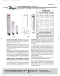
RK2
SYSTEMS
SAN DIEGO, CA
RK150PE-PF
PROTEIN FRACTIONATOR
Operations Manual
RK2 150 PE Protein Fractionator
I.
II.
III.
IV.
V.
Introduction
Tools, parts and hardware
Unpacking procedures
Assembly procedures
Appendix: Components
I. Introduction:
Congratulations on your purchase of the RK2 150 PE Protein Fractionator. This
sophisticated filtration system is recommended for aquaria of up to 10,500 gallons,
and, when operated and maintained correctly, will provide many years of service,
clean water, and health for aquatic life systems.
Should any technical issues arise during assembly or operation of this
unit, please contact your RK2 Systems Distributor.
II. Tools, Parts and Hardware
The RK2 150 PE is simple to assemble, with only a few tools necessary and very few
nuts, bolts and washers to keep track of.
Tools needed:
Phillips screwdriver
Flat head screwdriver
5/16 “ open-end wrench
1/2” open-end wrench
Teflon tape
Box-cutter or similar blade
One tube of Silicone Grease (recommended)
NOTE: Pipe wrenches are not recommended for assembly of the
150 PE and typically result in damage to the unit.)
Hardware included:
(For top assembly)
Twenty 5/16” x 2 1/4” bolts
Twenty 5/16” finished hex nuts
Twenty 5/16” x 3/4” standard flat washers
Twenty 5/16” x 1 1/2” fender washers
(For pump mount)
Four 1/4” x 1” bolts
Four 1/4” x 5/8” washers
III. Unpacking Procedures
1.
Remove the staples at the top of the carton and remove the lid. (See Fig. A)
HELPFUL HINT: The lid makes a useful tray to keep all parts together
for assembly.
2.
Remove the staples that attach the cardboard exterior to the wooden pallet.
(See Fig. A)
3.
Slip the box cover off the top of the unit.
4.
Cut and remove straps from boxes and pallet.
5.
Remove the screws that secure the base of the 150 PE to the pallet. (See Fig. B)
HELPFUL HINT: A hand-truck is a great way to move the 150 PE
around prior to final installation.
Fig. A
Fig. B
6.
Remove pipes from inside the large grey Reaction Chamber. (See Fig. C)
7.
Remove hanging tags from unit.
8.
Look for masking tape that holds O-rings in place on the end of pipe fittings.
Remove any masking tape whenever you see it. (See Fig. D)
Fig. C
9.
Fig. D
Unpack the Top & Cone Assembly from the larger box. (See Fig. E)
10. Set aside the Drop-Down Vent and Washer and Hardware Package. (See Fig. F1,
F2)
Fig. F1
Fig. F2
11. Remove all bubble wrap from the Top & Cone Assembly. (See Fig. E)
12. Remove bolts and washers from bottom of Top & Cone Assembly, set aside.
13. Remove Pump and Base from smaller box.
Fig. E
IV. Assembly Procedures
Assembly should take you no more than a few hours. Follow the instructions below
very carefully, taking special note of the Helpful Hints
, Notes
and
Warnings . This will help prevent breakage of any difficult-to-replace
components. The Appendix, located at the end of this document, identifies the
fixtures and assemblies you will be installing.
Again, should any technical issues arise during assembly or operation
of this unit, please contact your RK2 Systems Distributor.
Mounting the Top/Cone Assembly
1.
Separate the gaskets and parts as shown in Fig. 1.
2.
Apply grease to seal in a complete circle inside of the circle of bolt holes as
shown in Fig. 2.
HELPFUL HINTS: Do not get this grease on your clothes! It cannot
dry, which is one of the reasons it’s perfect for this job. As long as
you’ve got the grease on your finger, you can also apply it to the
rubber grommets as shown in Figs 9a and 9b, the Waste port in Fig.
10, and the intake port as shown in Fig. 24. However, if you do that
you’ll be skipping around so be sure to return back to Step 3, below,
after you’re finished greasing!
Fig. 1
Fig. 2
3.
Place either of the two gaskets (both are identical) on top of the Reaction
Chamber and align the holes as shown in Fig. 3.
4.
Apply grease to the top of the gasket, as in Step 2, above. (See also Fig. 4)
Fig. 3
Fig. 4
HELPFUL HINT: Remembering to apply a ring of silicon grease (as
shown above) inside the ring of bolt holes between all layers, you
can continue to assemble the Gaskets, Cone and Top Assembly using
the diagram shown below, and skip to Step 8. (Diagram not to scale)
5.
Place the cone on top of the gasket.
6.
Apply grease along the top of the cone, as shown in Step 2, above.
(See also Fig. 6)
Fig. 6
7.
Apply the second gasket to the rim of the cone.
8.
Apply grease to the top of the gasket, as in Step 2, above.
9.
Apply grease to the rubber grommets on the Top (lid) of the unit, as shown in
Figs. 9a and 9b.
Fig. 9a
Fig. 9b
10. Apply grease to the Waste Drain Port at the bottom of the Top (lid) assembly.
(See Fig. 10 and never mind the “Lube Pipe with Soap” message on the
grommet.)
Fig. 10
11. Insert the Air Vent into the hole at the top of the Top (lid), as shown in Fig. 11.
12. Insert the Drop-Down Washer, point it oriented toward the left of the center of
the unit. (See Fig. 12)
Fig. 11
Fig. 12
13. Place the Top (lid) on top of the gasket, and align the front of the Top Assembly
to the RK2 insignia as shown in Fig. 13.
14. Use a Phillips screwdriver to align the holes around the Top, through the
gaskets, and cone to the Reaction Chamber.
Fig. 13
Fig. 14
15. Position the 5/16” x 3/4” standard flat washers and insert the 2 1/4” bolts into
the 20 holes.
HELPFUL HINT: Initial bolt insertions may be more challenging
than subsequent ones. It is preferable to thread all bolts through the
holes rather than using a hammer or other implement to pound
them through.
WARNING: At this point you may be tempted to apply the fender
washers to the bottoms of the bolts and begin tightening them in
a circular pattern around the top. TRUST US: If you do one side at
a time, or go in a circular pattern, the result will be that one side
rises too high, unequal pressure will result, and the acrylic material may
fracture.
16. Once all the bolts are inserted, apply the fender washers and hand-tighten with
the nuts. (See Fig. 17a) AGAIN, do not tighten in a circular pattern.
17. Tighten all 20 nuts and bolts in a criss-cross pattern to opposite corners, as per
the Fig. 17a. Tighten until snug. (See Fig. 17b)
Fig. 17a
Fig. 17b
NOTE: The PSI of the water running through this part of the 150 PE
is extremely LOW. Because of that, and because of all the grease you
have applied, you do not need to tighten the bolts beyond what is
snug. Leave no more than 1/8 of the thread of the bolt exposed, as
shown in Fig. 17c.
Fig. 17c
Mounting the Pump
18. Position the Pump Base over the holes on the 150 PE Platform.
(See Fig. 18)
19. Place the Pump on top of the Pump Base. (See Fig. 19)
Fig. 18
Fig. 19
20. Using the 1/4” x 1” bolts and 1/4” x 5/8” washers provided, attach the Pump
and Pump Base to the 150 PE Platform, as shown in Fig. 20.
21. Hand-tighten the unions as shown in Fig. 21a until surfaces are flush. See
Fig. 21b to observe how the union looks when it is NOT flush.
WARNING: Do NOT USE A WRENCH to tighten this union, or a
rupture will most likely result. Do not over-tighten this union!
Fig. 21a
22. Remove bubble-wrap from all pipes.
23. Remove protective pipe inserts from clips.
24.
Grease the Intake Port. (See Fig. 24)
Fig. 24
Fig. 21b
25. Attach the Venturi Intake Assembly by doing the following:
A.
Position the ball valve handle outward. (See Fig. 25a)
B.
Secure the pipe click located above the Venturi. (See Fig. 25a)
C.
Join the lower union of the Venturi Intake Assembly to the pump, as
shown in Fig. 25b. Keep fairly loose.
D.
Join the upper union of the Venturi Intake Assembly to the Venturi.
(See Fig. 25a)
Fig. 25a
Fig. 25b
26. Attach the Air Intake Assembly. The non-threaded end attaches to the pipe
click, and the 1” union attaches to the Venturi’s Air Intake valve. Align
straight, as shown in Fig. 26.
27. Hand-tighten the unions described in steps 25a and 25b, above.
28. Attach the Air Gauge by inserting over the end of the Air Intake Assembly
and fasten it with the adjacent pipe click, as shown in Fig. 28.
WARNING: DO NOT GLUE the Air Gauge to the Air Intake
Assembly. Maintenance requires that this component be
removed and cleaned periodically.
Fig. 26
Fig. 28
29. Attach the Clear Sight Gauge to the pipe click and the 3/4” as shown in
Fig. 29.
Fig. 29
30. Take the 2” Discharge Air Vent and cover the threading with Teflon tape, as
shown in Fig. 30.
Fig. 30
31. Attach the 2” Air Vent by threading it into the 4” Discharge “T” Fitting, as
shown in Fig. 31. Hand-tighten until snug.
Fig. 31
32. Install the External Wash Control Timer Assembly, which contains a
Solenoid Valve and Timer Control.
A.
Place the External Washer Control by fitting it into the grooves on the
black bracket. (See Fig. 32a)
B.
Thread the long end of the External Wash Assembly (attached to the
External Washer Control) to the 3/4” union on the Top (lid) assembly,
and secure with pipe click in middle and _______ Valve on bottom. (See
Fig. 32b) (pics don’t show bottom valve attachment.)
Fig. 32a
Fig. 32b
33. Slide the Intake Valve Assembly into the rubber grommet on the side of the
Reaction Chamber, as shown in Fig. 33.
Fig. 33
34. At the back of the unit, slide the Waste Drain into the 2” rubber grommet.
Secure with the adjacent pipe click. (See Fig. 34)
Fig. 34
35. Install the Internal Wash Timer Assembly (which includes a Solenoid Valve
and Timer Control).
A.
Attach Timer Control to the bracket located on the Venturi Intake
Assembly, as shown in Fig. 35a.
B.
Temporarily remove the Ball Valve from the Solenoid Assembly.
C.
Thread the Ball Valve into the top of the Venturi Intake Assembly with
the handle facing outward, as shown in Fig. 35b.
D.
Attach the Solenoid Assembly to the 2 3/4” union on the Internal DropDown Wash Assembly, as shown in Figs. 35c and 35d.
Fig. 35a
Fig. 35c
Fig. 35b
Fig. 35d
Congratulations! You have successfully assembled the RK 150 PE! Now it’s time
to plumb the RK 150 PE to the outside world.
36.
Plumb the dirty water to the 2” Ball Valve Intake.
37.
Plumb the Waste Drain to the sewage line.
38.
Plum the 4” Discharge to reservoir.
WARNING: Immediately after the 4” Discharge, you must provide a
minimum of 12” vertical drop. Do not install horizontal piping until
you have provided 12” of vertical drop.
39. After you have completely connected the RK 150 PE, fire it up! Then inspect
for any unions or nuts/bolts that leak, and hand tighten.
Appendix: Components
Included within the Reaction Chamber (main structural component of the RK 150
PE) and accompanying boxes there are some components wrapped in bubblewrap that you will need to install. They are shown below for your reference:
Venturi Intake Assembly
External Wash Timer Assembly
Air Intake Assembly
Discharge Air Vent
Sight Gauge
Air Gauge
Appendix (continued)
Top Air Vent
Intake Valve Assembly
Internal Wash Timer Assembly
Internal Drop-Down Wash Assembly
Waste Drain
RK150PE
PROTEIN FRACTIONATOR
FLOW RATE 150GPM @ 2 MIN. DWELL
HDPE Molded Tank
ozone vent union
internal rinse system
seawater - 1 nozzle jet
retracting
upper riser chamber
clear acrylic
Clear Sight Gauge
(Tank level monitor)
riser configuration
external rinse system
high pressure - freshwater
4 nozzle jets.
effluent drain union
back-side of
upper riser chamber
(not shown)
electronic interval timer
3/4" fipt (rinse system) x2
2" vent - (discharge manifold)
005
052
05
venturi anti-siphon
air/ozone intake
3" intake SCH80 flange Soc
(standard locations
@ 90 or 270 .)
101”
Kynar venturi
220 cfh gas injection
6230 clh. w/ ozone
& anti-syphon connx.
filter discharge
return manifold
4.0”
60.0"
reaction chamber
HDPE custom molded
36"dia. (46cm dia.)
level control valve
Dedicated venturi pump
13.8/6.9 amp max.
@115/230v 50/60Hz 1ph.
Floor
HDPE Pump pad
18"x24"x3"
36.0”
copyright 2000-2008 RK2 SYSTEMS, INC. Any use of this design without the written permission of RK2 SYSTEMS is prohibited.
RK150PE PROTEIN FRACTIONATOR
PORT CONNECTION CONFIGURATIONS
RK75PE PLAN
PORT ORIENTATION
TOP VIEW:
337.5
0
36"
67.5
PROTEIN
FRACTIONATOR
20.125"
270
Alternate
1st Alternate
54"
26.625"
22.25"
2.00"
VENTURI/PUMP
ASSEMBLY
90
180
4” T
4” T
PUMP PAD
18"x24"x3"
MOLDED IN HOLD DOWNS
.5” HOLE
15.50"
= FILTER INLET. 3" PVC STD. FLANGE, HORIZONTAL POSITION. HEIGHT = 58.50"
= EFFLUENT DRAIN. 2" PVC SCH40 SLIP UNION, HORIZONTAL POSITION. HEIGHT = 72.75”.
= FILTER DISCHARGE. 4" PVC SCH40 SLIP TEE, HORIZONTAL POSITION. HEIGHT = 60.0"
GRAVITY DRAIN, INITIAL 12" MUST DROP VERTICALLY, NO LATERAL PIPING.
copyright 2000-2008 RK2 SYSTEMS, INC.
Any use of this design without the written
permission of RK2 SYSTEMS is prohibited.
= OZONE VENT. 1" PVC SCH40 SLIP UNION. HEIGHT = 101”
= RINSE SYSTEMS. ELECTRONIC CONTROL VALVES 3/4 MIPT.
2 - 9V BATTERY PER VALVE.
Owners Manual
Professional Quality
Corrosion Resistant
Energy-Efficient
Centrifugal Pumps
RK2 Pumps are end suction centrifugal units that are
close coupled to 56J motors. They feature excellent
corrosion resistance with molded Noryl pump
housings, 316 ss hardware, pump seals of Monel
ceramic and buna, and motors with PVC encapsulated
stainless steel motor shafts. Numerous electrical
motor configurations are available.
WARNING: PLEASE READ COMPLETELY
BEFORE YOU INSTALL OR OPERATE YOUR
NEW PUMP! NEVER RUN PUMP DRY! NEVER
REVERSE ROTATION! NEVER EXCEED AN
INTERNAL CASE PRESSURE OF: 100 PSI MAX
NORYL
Thank you for choosing an RK2 System pump. It has been designed and built to
provide you with years of dependable service. To insure maximum performance,
we urge you to carefully follow the instructions in this manual.
If you have any questions, call your nearest distributor or (760) 746-7400 for
assistance.
Installation
Proper installation of your pump will help it to provide you with dependable, trouble free service. Please
follow the general guidelines listed below to help insure maximum performance.
1. Position the pump as near the water intake source and as low as is practical. This will help avoid
cavitation and maximize your pumps output.
2. Protect the motor from excessive heat and moisture. It is best to provide shade from direct sun, and
insure that it has proper ventilation. Excessive heat will shorten the motor life and void the warranty.
3. Protect the motor against dirt, water and all foreign matter. If the motor has been flooded, shut off
power and do not operate it until it has been checked by an authorized motor technician, and it has
been certified safe to operate. If the motor is damaged by dirt or moisture it voids the warranty.
4. Mount the motor where it cannot become submerged.
5. The fittings used to connect to the housing should be plastic. All plumbing lines should be self
supported and properly aligned. This will prevent undue stress to the housing.
6. The intake to the pump should never be restricted. Keep your suction lines as free of elbows, fittings
and valves as possible. The use of large diameter pipe will help provide adequate flow, as it
reduces friction loss.
7. This is a non self priming pump and is best suited with a flooded suction. The pump housing, and the
entire suction line must be filled with fluid for it to operate properly. Do not run dry!
Electrical
1. Make sure the power is disconnected at the breaker before wiring the motor.
2. Make sure that the motor is wired so that it matches the supply voltage (115, 208, 230 or 460 volt). If
they do not match it will damage your motor and void the warranty.
3. Use a wire of adequate gauge and length to prevent electrical line losses. The use of heavier
gauge wire will allow the motor to run cooler and more efficiently.
4. Make sure all connections are clean and tight. Properly ground the motor. (There is normally a
green ground terminal located on the inside of the motor connection box.) Make sure the ground
wire is properly connected to an electrical service ground. Connect the pump permanently to an
adequately sized circuit. It is best to have a dedicated circuit that won’t suffer voltage drop from
other loads.
¸ ¸ ¸ THREE PHASE MOTORS:¹ ¹ ¹
5. Insure proper motor rotation. When viewed from the shaft end, the motor must rotate
counterclockwise. Incorrect rotation will destroy the pump and motor.
Note: The motor leads must be energized in the correct order. If you are not sure of the
sequence of your incoming supply line, remove the volute from the pump, connect the power
and check rotation. When the rotation is correct, reinstall the volute. Do not test with volute in
place! Never test rotation by bumping a switch!!! This will destroy the pump and void the
warranty!!!! If it is incorrect, exchange any two of the connected leads and retest.
-2-
Disassembly
1. Shut off the power to the motor
before disconnecting any
electrical wiring from the back of the
motor.
2. Disassemble the volute from the
bracket motor assembly by removing
the seven ¼ 20 x 2 ¾ cap screws.
(The volute may be left in-line if you
wish.)
3. Remove the cap covering the back
end of the motor shaft and with a large screwdriver or wrench, prevent shaft rotation while
unscrewing the impeller counterclockwise.
4. Remove the ceramic piece from the impeller hub.
5. Detach the bracket from the motor by removing the four 3/8” cap screws, and slide it forward,
away from the motor.
6. Remove the carbon-graphite seal from the bracket by pressing it out from the back. Do not dig
it out from the front!
Pump End Assembly
1.
2.
3.
4.
Check all pump parts and clean as needed.
If the motor shaft has corrosion build up, use emery cloth to clean it.
Install the O-ring into the O-ring gland in the bracket bore.
Press the carbon seal head into the bracket bore. CAUTION! Press only on the stainless steel
or polypropylene shell, NOT ON THE DELICATE CARBON FACE! DO NOT TOUCH THE
CARBON SEAL FACE!
5. Note: It is not recommended to use a slinger in conjunction with a PVC shaft sleeve.
6. Mount the bracket onto the motor C-face using four 3/8” cap screws and tighten them snugly.
7. Press the ceramic into the impeller hub. It helps to moisten the rubber boot with water first.
The ceramic MUST SIT FLAT. If one side is higher than the other, the seal will leak! The
smooth face must be up and exposed.
8. Screw the impeller clockwise onto the motor shaft and tighten. You can hold the shaft
stationary at the opposite end of the motor with a large screwdriver or wrench..
9. Place the large O-ring in the groove in the volute. Note: It is easiest to lay the volute, suction
side down, place the O-ring in the groove, and lower the bracket/motor assembly down onto
the volute. (So the O-ring doesn’t pop out.)
10. Install the seven 1/4” x 2 3/4” socket cap screws with washers and tighten in a cross pattern
until they are reasonably snug. (No need to overtighten).
11. Place the small O-rings onto both drain plugs, and screw them into the 1/4” holes in the
volute and bracket.
-3-
Trouble Shooting Aid
Motor Will Not Start
1. Check for voltage present at connection box.
2. Check that the supply voltage matches the motor voltage connections.
3. Check that you have proper line voltage.
4. Check that all connections are sound.
5. Check that the motor shaft rotates easily by hand. (This can be checked at the rear of motor by
turning with screwdriver or wrench.)
Motor Won’t Start, But It Hums.
1. Check items 2-5 above.
2. Check that there is no foreign matter lodged between the contacts on the start switch.
3. Check to insure the capacitor is functioning properly.
Motor Gets Hot And Shuts Down.
1. Check for proper wiring in the motor box. The supply voltage must match the motor voltage
connections.
2. Check the voltage at the motor box, with the motor and all other loads normally on the circuit
running. It must not be significantly below the nominal voltage.
3. Check to see if the motor shaft turns without excessive resistance. Bad bearings, or a clogged
impeller can cause excessive resistance.
4. Make sure any check valves are installed in the correct direction.
5. Check that the pump impeller and the housing are not clogged or blocked.
Pump Will Not Hold A Prime.
1. Check for defective joints at all pipe fittings. They must be air tight.
2. Check for a defective check valve or foot valve.
3. Check for a leaking seal.
-4-
Bulletin F-43
9/14/05
9:01 AM
Page 1
Bulletin F-43
®
Series RM Rate-Master Flowmeters
Specifications - Installation and Operating Instructions
Dimensions in Inches
(Centimeters)
Model RMA Model RMB Model RMC
A
B
A
4 -9/16 (11.59)
B
3 (7.62)
6-7/16 (16.35)
1/8 NPT CONN. 1/4 NPT CONN.
J
BACK WIDTH
F
K
C
E
8-1/2 (21.59)
15 -1/8 (38.42)
12 -1/4 (31.12)
1/2 NPT CONN.
C
1-5/8 (3.17)
10 - 32 Thds.
3-15/16 (8.56)
1/4 - 20 Thds.
8-3/4 (10.72)
10 - 32 Thds.
D
3/8 (.95)
5/8 (1.59)
1 (2.54)
E
1-1/16 (2.60)
1-7/8 (3.42)
2-3/4 (5.83)
F
1-3/16 (2.73)
1-3/4 (3.29)
2-1/4 (5.33)
G
3/4 (1.91)
1 (2.54)
1-7/16 (2.98)
H
1 (2.54)
1-7/16 (2.98)
1-31/32 (3.51)
I
(OPEN)
1-3/8 (3.49)
1-13/16 (4.60)
2-1/2 (6.35)
J
3/4 (1.91)
1-1/4 (3.18)
2 (5.08)
K
4-13/16 (12.22)
8-3/4 (22.23)
15-3/8 (39.05)
L
1 (2.54)
1-1/2 (3.81)
2-1/4 (5.72)
D
PANEL CUTOUT FOR FLUSH MOUNTING
I
FULL OPEN
G
H
Fig. 1
Fig. 2
L
HIGH
WIDE
Dwyer Series RM Rate-Master Flowmeters are furnished in three
models (see Fig. 2), each available in a broad array of flow ranges with
direct reading scales for air, gas or water. Installation, operation and maintenance are very simple. Only a few common-sense precautions must be
observed to assure long, trouble-free service.
CAUTION: Dwyer Rate-Master® Flowmeters are designed to provide satisfactory long-term service when used with air, water or other compatible
media. Refer to factory for information on questionable gases or liquids.
Avoid solutions of acids, bases or salts having a pH below 5.0 or above
8.5. Caustic solutions, antifreeze (ethylene glycol) and aromatic solvents
should definitely not be used.
Calibration
Each Rate-Master® Flowmeter is calibrated at the factory. If at any time
during the meter’s life, you wish to re-check its calibration, do so only with
devices of certified accuracy. DO NOT attempt to check a Rate-Master®
Flowmeter with a similar flowmeter, as seemingly unimportant variations in
piping and back pressure may cause noticeable differences in the indicated reading. If in doubt, return your Dwyer Rate-Master® Flowmeter to the
factory. Its calibration will be checked for you at no charge. Before proceeding with installation, check to be sure you have the Rate-Master
model and flow range you require.
LOCATION: Temperature, Pressure, Atmosphere and Vibration:
Dwyer Rate-Master® Flowmeters are exceptionally tough and strong. They
are designed for use at pressures up to 100 psi (6.89 bar) and temperatures up to 130°F (54°C).
DO NOT EXCEED THESE LIMITS! The installation should not be exposed
to strong chlorine atmospheres or solvents such as benzene, acetone,
carbon tetrachloride, etc. The mounting panel should be free of excessive
vibration, as it may prevent the unit from operating properly.
DWYER INSTRUMENTS, INC.
P.O. BOX 373 • MICHIGAN CITY, IN 46361, U.S.A.
8-9/16 (21.75)
15 -3/16 (38.58)
7/8 (2.22)
1-5/16 (3.33)
2-1/16 (5.24)
PANEL HOLE SIZES FOR SURFACE MOUNTING
5/8 (1.59)
15/16 (2.38)
7/16 (1.11)
PIPE
BOLT
®
4-5/8 (11.75)
1/4 (0.64)
9/32 (0.71)
13/32 (1.03)
Inlet Piping Run: It is good practice to approach the flowmeter inlet with
as few elbows and restrictions as possible. In every case, the inlet piping
should be at least as large as the connection to the flowmeter; i.e.,1/8″
Iron Pipe Size for RMA models 1/4″ IPS for RMB models,1/2″ IPS for RMC
models. Length of inlet piping makes little difference for normal pressurefed flowmeters.
For flowmeters on vacuum air service, the inlet piping should be as short
and open as possible. This will allow operation near atmospheric pressure
and thereby insure the accuracy of the device. (Note: for vacuum air service, the flow control valve, if any, should be on the discharge side of the
flowmeter. Either the TMV unit or a separate in-line valve may be applied.).
Discharge Piping: As on the inlet, discharge piping should be at least as
large as the flowmeter connection. Also, for pressure-fed flowmeters on
air or gas service, the discharge piping should be as short and open as
possible. This will allow operation of the flow tube at near atmospheric
pressure and insure the accuracy of the device. This is of less importance
on water or liquid flowmeters, as the flowing medium is generally incompressible and moderate back pressure will not affect the accuracy of the
instrument as calibrated.
POSITIONING AND MOUNTING
All Rate-Master® Flowmeters must be mounted in a vertical position with
inlet connection at the bottom rear and outlet at the top rear.
Bezel or Through-Panel Mounting: Make panel cutout using appropriate dimensions from Fig. 2. Flowmeter must fit into panel freely without
forcing or squeezing. Insert the flowmeter from the front of the panel and
install the mounting clamps from the rear. Insert and tighten the clamp
bolts in the locations shown in Fig. 3. Do not exceed 5 in./lbs. Make connections to inlet and outlet ports using small amount of RTV sealant or
Teflon® thread tape to avoid leakage. Avoid excess torque, which may
damage the flowmeter body.
Phone: 219/879-8000
Fax: 219/872-9057
www.dwyer-inst.com
e-mail: [email protected]
Bulletin F-43
9/14/05
9:01 AM
Page 2
Fig. 6
Fig. 5
MOUNTING
BRACKET
SCREW 4
REQUIRED
Fig. 3
Fig. 4
Fig. 5B
Surface Mounting: Drill appropriate holes in panel, using the dimensions
shown in Fig. 2. Hold the flowmeter in position in front of the panel and
install the clamp bolts from the rear. (The mounting clamps may be used
as washers, if desired, by installing them backwards or straightening them
out.) Pipe up inlet and discharge following the directions in the previous
sections.
Surface Mounting on Piping Only: An alternate method of surface
mounting, omitting the clamp bolts and supporting the flowmeter solely on
the connecting piping, is possible. For this method, extra-long or straight
pipe threads should be used so that nuts may be run onto the pipe and
later tightened against the back of the panel to retain the unit in proper
position. Use appropriate hole layout in formation from Fig. 2, but omit the
small holes.
Surface Mounting on Piping Only Without Panel: For a temporary or
laboratory type installation, the panel may be omitted altogether and the
flowmeter installed directly in rigid piping. Its light weight permits this without difficulty.
OPERATION
To start system, open valve slowly to avoid possible damage. Control
valves on BV and SSV models are turned clockwise to reduce flow,
counter-clockwise to increase flow. A nylon insert is provided in the threaded section of the valve stem to give a firm touch to valve and to prevent
change of setting due to vibration.
The performance of low range units used in air or gas applications may be
affected by static electricity. Excessive static charge may cause the ball
float to behave erratically or provide a false reading. To ensure the proper
function of the unit, the application should be designed to minimize or dispel static electricity.
The standard technique for reading a Variable Area Flowmeter is to locate
the highest point of greatest diameter on the float, and then align that with
the theoretical center of the scale graduation. In the event that the float is
not aligned with a grad, an extrapolation of the float location must be made
by the operator as to its location between the two closest grads. The following are some sample floats shown with reference to the proper location
to read the float.
Variable Area Flowmeters used for gases are typically labeled with the prefix “S” or “N”, which represents “Standard” for English units or “Normal” for
metric units. Use of this prefix designates that the flowmeter is calibrated
to operate at a specific set of conditions, and deviation from those standard conditions will require correction for the calibration to be valid. In practice, the reading taken from the flowmeter scale must be corrected back to
standard conditions to be used with the scale units. The correct location to
measure the actual pressure and temperature is at the exit of the flowmeter, except when using the Top Mounted Valve under vacuum applications,
where they should be measured at the flowmeter inlet. The equation to correct for nonstandard operating conditions is as follows:
Q2 = Q1 x
Where:
P1 x T2
P2 x T1
Q1 = Actual or Observed Flowmeter Reading
Q2 = Standard Flow Corrected for Pressure and
Temperature
Fig. 6B
Fig. 7
P1 = Actual Pressure (14.7 psia + Gage Pressure)
P2 = Standard Pressure (14.7 psia, which is 0 psig)
T1 = Actual Temperature (460 R + Temp °F)
T2 = Standard Temperature (530 R, which is 70°F)
Example: A flowmeter with a scale of 10-100 SCFH Air. The float is sitting
at the 60 grad on the flowmeter scale. Actual Pressure is measured at the
exit of the meter as 5 psig. Actual Temperature is measured at the exit of
the meter as 85°F.
Q2 = 60.0 x
(14.7 + 5) x 530
14.7 x (460 + 85)
Q2 = 68.5 SCFH Air
CAUTION: Do not completely unscrew valve stem unless the flowmeter is
unpressurized and drained of any liquid. Removal while in service will allow
gas or liquid to flow out the front of the valve body and could result in serious personal injury. For applications involving high pressure and/or toxic
gases or fluids, special non-removable valves are available on special
order. Please contact factory for details.
MAINTENANCE
The only maintenance normally required is occasional cleaning to assure
reliable operation and good float visibility.
Disassembly: The flowmeter can be disassembled for cleaning
simply as follows:
1. Remove valve knob from RMB or RMC -BV or -SSV units by pulling the
knob forward. It is retained by spring pressure on the stem half-shaft so
that a gentle pull will remove it. On RMA-BV or -SSV models, turn the valve
knob counter-clockwise until the threads are disengaged. Then withdraw
the stem from the valve by gently pulling on the knob.
2. Remove the four mounting bracket screws located in the sides of the
flowmeter. See Fig. 3. Pull the flowmeter body gently forward away from
the back plate to avoid undue strain on the body. Leave the piping connections intact. There is no need to disturb them. See Fig. 4.
3. Threaded body style flowmeters - Remove the slip cap with a push on
a screwdriver as shown in Fig. 5. Remove the plug ball stop as shown in
Fig. 6 using allen wrench sizes as follows: Model RMA - 1/4″, Model RMB
- 1/2″ and Model RMC - 3/4″ Threadless body style flowmeters - Release
the plastic retaining clip with a screw driver (Figure 5B), it will unclip from
the valve body (TMV Option) or the plug ball stop, slide the clip back until
the valve body or ball stop can be removed. The clip will remain in the body
for convenience. Using a screwdriver gently lift up on the plug in the groove
as shown in Figure 6B until the o-ring seal is released and remove the plug.
For the TMV option gently pull up on the valve knob to release the valve
body seals and remove the valve.
4. Take out the ball or float by inverting the body and allowing the float
to fall into your hand, as shown in Fig. 7. (Note: It is best to cover the discharge port to avoid losing the float through that
opening.)
Cleaning: The flow tube and flowmeter body can best be cleaned with a
little pure soap and water. Use of a bottle brush or other soft brush will aid
the cleaning. Avoid benzene, acetone, carbon tetrachloride, alkaline detergents, caustic soda, liquid soaps (which may contain chlorinated solvents),
etc. Also, avoid prolonged immersion, which may harm or loosen the
scale.
Reassembly: Simply reverse steps 1 through 4 and place the flowmeter
back in service. A little stopcock grease or petroleum jelly on the “O” rings
will help maintain a good seal as well as facilitate assembly. No other special care is required.
Teflon® is a registered Trademark of E.I. DuPont Company
©Copyright 2005 Dwyer Instruments, Inc.
Printed in U.S.A. 9/05
DWYER INSTRUMENTS, INC.
P.O. BOX 373 • MICHIGAN CITY, IN 46361, U.S.A.
Phone: 219/879-8000
Fax: 219/872-9057
FR# 56-440197-00 Rev. 16
www.dwyer-inst.com
e-mail: [email protected]
Proper Protein Fractionator Adjustment
A protein skimmer (actually a protein fractionator) is not a 'plug and play' piece of equipment. It requires
close attention to achieve proper adjustment. This proper adjustment is critical to achieving the maximum
performance from the unit.
The fractionator is adjusted by creating back pressure at the discharge by throttling the discharge valve.
The gas intake and water inlet need to be set to their recommended flow rates. Throttling back the
discharge valve increases the back pressure and raises the foam level in the upper chamber. This is
basically a hydraulic balancing procedure. (Do not throttle water or air flow to and from the venturis to
control foam height. Venturi water valves should run in the open position. Venturi air intakes should be
adjusted to a 1” to 2” vacuum.)
The fractionator needs to be adjusted to a level that consistently produces an effluent the color of weak tea
or ginger ale. Lowering the foam level to the point where it only produces dry foam and a dark effluent
inhibits the removal of waste products. A new installation that has not had any fractionation for more
than a few days will require 2 to 7 days for the system to achieve a level of stable organic removal.
Protein fractionators remove compounds from the water by injecting fine bubbles into the water.
Organic compounds 'stick' to the surface tension of the water which includes the surface of the bubbles.
As the organic laden foam rises into the upper chamber it overflows into the collection area.
The discharge valve adjustment combined with the Bio-load (and certain additives) will affect the foam
level. If the foam level is set too low the protein fractionator will only remove a small amount of waste
even from very dirty water. Waste levels which are below this threshold remain in the water since the
protein fractionator is not adjusted to remove them. The result of this level of adjustment is a very dark,
concentrated waste extract from the protein fractionator. When this is occurring the aquarist has no way
of determining how efficient the protein fractionator is working other than by observing the color of the
water in the aquarium.
Adjusting the level too high creates a situation where the fractionator is removing a large amount of water
that has very little dissolved organics.
To properly adjust a protein fractionator takes at least several days of observation and adjustments. You
should allow a minimum of a half an hour between adjustments to allow the hydraulics to settle into
balance. There are a couple things to remember to achieve proper adjustment. The first is the protein
fractionator only removes waste to the threshold you have set. As it approaches this threshold it removes
less and less resulting in a concentrated extract. The other is that the extract should be roughly the color of
ginger ale or weak tea. If it is darker, the threshold is set too low.
To adjust the fractionator properly the following must be done:
1. Make sure the venturi and inlet flows are set to the recommended rates.
2. Adjust the protein fractionator by throttling the discharge valve so that the extract is about the color of
ginger ale or weak tea. Ideally you will produce a sudsy foam that is between the consistency of water
and shaving cream.
3. Let it run, even though it may run wet for a while. As it approaches the new threshold level for waste
extraction it will begin to slow down and the extract will become darker and more concentrated. When
this happens repeat step 1 and step 2.
3. When the point is reached that the protein fractionator does not slow down after a few days then it can
be assumed that the protein skimmer is properly adjusted. In the case of very dirty water this process may
take quite a number of adjustments and may take longer to slow down the first time. Keep the protein
fractionator adjusted so that the extract does not become dark.
Adding feed, organic matter or animals to the water will cause the foam level to rise, sometimes
substantially. Certain oils and other compounds will inhibit foam production. If the skimmer level
“bounces” or changes radically over a short period, there may be hydraulic issues with the way the filter
is plumbed and/or vented.
NEVER BLOCK THE DISCHARGE VENT UNION AT THE TOP OF THE FRACTIONATOR. This
will pressurize the unit, and void all warranties. If you connect any filters or ozone destruct equipment to
the top vent, the vent must remain free-flowing or at a slightly negative pressure.
To maintain an efficient fractionator the upper chamber must remain clean and the rinse system in the
upper chamber needs to be working properly. The chamber should be accessed through the top cover and
cleaned manually every 90 days or if the rinse system has been out of operation for more than 3 hours.
With a properly adjusted protein fractionator the water will be noticeably cleaner. Ideally aquarium water
should be clear and colorless. The closer to this goal the better.
PRODUCT WARRANTY TERMS
RK2 Systems, Inc. (The Seller) warrants to the original purchaser, that products of its own
manufacture will be free from defects in materials or workmanship, under normal use and
service, for a period of one year from the date of purchase (with the exception of a vessel, which
is warranted for three years). The Seller’s obligations under this Warranty are limited to
replacing or repairing or giving credit for, at its option, any of its said products which shall,
within one year after purchase, be returned to the Seller’s place of origin, transportation charges
prepaid, and which are, after products examined, disclosed to the Seller’s satisfaction to be thus
defective. This Warranty does not apply to defects caused by shipping damages, or to any
products manufactured by Seller which have been subject to improper installation, misuse,
neglect, accident, ordinary wear and tear, or Buyer’s attempts to use any products beyond its
mechanical, thermal, or electrical capacity. Notice of a defective product must be given to Seller
in writing within 48 hours of discovery and be free, without limitation of labor charges, lost
profits, expenses of repair or other costs incidental to replacement. All transportation costs
incurred in shipping product to or from Seller’s plant shall be at the Buyer’s expense. The
aforementioned provisions do not extend the original Warranty period of any product which has
either been partially repaired or replaced by the Seller.
FOR FURTHER TECHNICAL ASSISTANCE
Contact your RK2 distributor