1
PowerSpout Basic System Design
and Installation Manual
PLT, TRG and LH turbines
Industrial PLT
Off grid domestic PLT
Grid connected domestic PLT
Domestic TRG
Domestic LH
Please read this manual carefully before beginning installation.
© 2014 EcoInnovation Ltd (NZ)
Page 1
CONTENTS
1.
Scope of Application, and Safety ................................................................................ 9
1.1.
1.2.
1.3.
1.4.
1.5.
1.6.
1.7.
1.8.
2.
Turbine serial numbers .................................................................................................. 9
Installation checklist .................................................................................................... 10
CE and FCC Declaration ................................................................................................ 11
Standards and certification .......................................................................................... 11
Pre-requisites .............................................................................................................. 11
Fairing safety warnings ................................................................................................ 13
Pressurised water pipes............................................................................................... 13
Connecting to the Grid (power network) ...................................................................... 14
Step by step design overview ................................................................................... 15
2.1. Survey your site .......................................................................................................... 15
2.2. On or off-grid electrical system? .................................................................................. 15
2.3. Battery voltage choice ................................................................................................. 15
2.4. Direct connection or MPPT? ........................................................................................ 15
2.5. Cable voltage .............................................................................................................. 16
2.6. AC coupling ................................................................................................................. 16
2.7. Over-voltage protection or not? .................................................................................. 16
2.8. Using surplus energy ................................................................................................... 16
2.9. Optional extras you may wish to order ........................................................................ 17
2.9.1.
Bearings......................................................................................................................... 17
2.9.2.
Manifold fittings ............................................................................................................ 17
2.9.3.
Spare jets....................................................................................................................... 17
2.9.4.
Adjustable jet options ................................................................................................... 18
3.
Renewable energy from a PowerSpout turbine ........................................................ 19
3.1. How much power will the PowerSpout produce? ......................................................... 19
3.1.1.
Head and Flow .............................................................................................................. 19
3.1.2.
Estimating the power output ........................................................................................ 20
3.1.3.
Worked example ........................................................................................................... 21
3.1.4.
Supply and Demand issues............................................................................................ 21
3.2. How to match the constant power supply to our changing demands? ........................... 21
3.3. What happens if there is not enough water for the turbine? ........................................ 21
3.4. How can we be sure of getting the right voltage out of the turbine? ............................. 22
3.4.1.
Voltage and turbine speed ............................................................................................ 22
3.4.2.
Manual optimisation of the turbine ............................................................................. 22
3.5. Understanding open circuit voltage (Voc)..................................................................... 23
4.
Designing your site layout and choosing your turbine model .................................... 24
4.1. Measuring Head .......................................................................................................... 24
4.2. Measuring Flow........................................................................................................... 25
4.3. Choosing the correct turbine for your site .................................................................... 25
4.4. Siting your PowerSpout turbine ................................................................................... 27
4.4.1.
Choose a place that is accessible. ................................................................................. 27
4.4.2.
Choose a site that has the most fall .............................................................................. 27
4.4.3.
Keep your PLT/TRG turbine as low as possible ............................................................. 28
4.4.4.
Place it as close to your battery bank or point of grid connection as possible, ........... 28
4.4.5.
Hydro turbines do make some noise, so keep them at least 30 m from your home. .. 28
4.5. Connecting two small streams into one PowerSpout .................................................... 28
© 2014 EcoInnovation Ltd (NZ)
Page 2
4.6. PowerSpout site data requirements............................................................................. 29
4.7. The Penstock............................................................................................................... 30
4.7.1.
Pipe sizes ....................................................................................................................... 31
4.7.2.
Pipe material ................................................................................................................. 31
4.7.3.
MDPE and HDPE pipes .................................................................................................. 31
4.7.4.
PVC pipes....................................................................................................................... 32
4.7.5.
Pipe myths..................................................................................................................... 32
4.7.6.
Laying and securing pipes ............................................................................................. 33
4.7.7.
Penstock valves ............................................................................................................. 33
4.7.8.
Pipe thrust blocks .......................................................................................................... 34
4.8. Intake design and placement ....................................................................................... 34
4.8.1.
Water usage with minimum impact on the environment ............................................ 36
4.9. Turbine "manifold" connecting options PLT and TRG .................................................... 37
4.9.1.
Connecting your pipe to the PowerSpout..................................................................... 37
4.9.2.
Recommended manifold pipe sizes .............................................................................. 37
4.9.3.
Quick connections ......................................................................................................... 37
4.9.4.
The connections made to the penstock ........................................................................ 38
4.9.5.
Bolt over saddles ........................................................................................................... 38
4.9.6.
Pipe fittings - Y’s ............................................................................................................ 39
4.9.7.
PVC 4 jet manifold – for PVC pipes and the TRG turbine.............................................. 40
4.9.8.
PVC manifolds for our PLT turbines .............................................................................. 40
4.9.9.
Pipe fittings - T’s and 90 degree elbows ....................................................................... 40
4.9.10. Mock up your manifold off-site first ............................................................................. 41
4.9.11. Other manifold options................................................................................................. 41
4.9.12. Measuring pressure in your pipe and manifold ............................................................ 41
4.9.13. Pipe supports ................................................................................................................ 42
5.
Electrical System Components ................................................................................. 43
5.1. "Smart Drive" Permanent Magnet Alternator (PMA) .................................................... 43
5.1.1.
Rectifier ......................................................................................................................... 43
5.2. Unloaded rpm and Open Circuit Voltage (Voc) revisited (see also 3.5) .......................... 44
5.3. PowerSpout standard voltage options ......................................................................... 44
5.3.1.
PowerSpout PLT and TRG turbines............................................................................... 44
5.3.2.
PowerSpout LH turbines ............................................................................................... 44
5.3.3.
Klampit "crowbar" protection circuits (optional) ......................................................... 45
5.3.4.
PowerSpout PLT versions .............................................................................................. 45
5.3.5.
PowerSpout TRG versions ............................................................................................. 46
5.3.6.
PowerSpout LH.............................................................................................................. 46
5.3.7.
Special PowerSpout options ......................................................................................... 46
5.4. Cable sizing ................................................................................................................. 46
5.5. Charge controller choice .............................................................................................. 47
5.5.1.
Diversion load controllers ............................................................................................. 47
5.5.2.
MPPT (Maximum Power Point Tracking) controllers .................................................... 48
5.6. Diversion (PWM) load battery-charge controllers in detail ........................................... 48
5.6.1.
Multiple energy sources and diversion load controllers............................................... 49
5.6.2.
Backup diversion load controller .................................................................................. 49
5.7. Maximum power point tracking (MPPT) controllers in detail ........................................ 50
5.7.1.
Maximising power ......................................................................................................... 50
5.7.2.
Higher cables voltages .................................................................................................. 50
5.7.3.
Compatibility issues ...................................................................................................... 50
5.7.4.
MPPT battery-charge controllers on the market .......................................................... 51
5.7.5.
Battery voltage options for MPPT controllers .............................................................. 53
© 2014 EcoInnovation Ltd (NZ)
Page 3
5.7.6.
Factoring in the cable voltage drop .............................................................................. 54
5.7.7.
Summary: Matching your turbine to an MPPT controller and your battery ................ 55
5.7.8.
Illustrative example....................................................................................................... 55
5.7.9.
Legal limits to voltage (extra low voltage) .................................................................... 56
5.7.10. Future trends ................................................................................................................ 57
5.8. Water and air diversion resistors ................................................................................. 57
5.8.1.
Diversion via the inverter output .................................................................................. 59
5.9. Diversion Load: Hot Water Element ............................................................................. 59
5.9.1.
Common water elements 12/24/48V ........................................................................... 60
5.9.2.
Common water elements 120/240V............................................................................. 60
5.10.
Diversion Load: Air-Resistive Coil ............................................................................. 60
5.10.1. Common air elements 12/24/48 V ............................................................................... 60
5.10.2. Common air elements 120/240 V ................................................................................. 61
5.10.3. Common 120 V and 240 V elements used at different voltages .................................. 61
5.11.
Using AUX “PV trigger” relay settings ....................................................................... 61
5.12.
Preventing excessively hot water with PWM & MPPT regulation .............................. 64
5.13.
Battery Bank (see also Section 7) ............................................................................. 64
5.14.
Grid connect inverters ............................................................................................. 65
5.14.1. MPPV and Voc considerations ...................................................................................... 67
6.
System Wiring ......................................................................................................... 68
6.1. Fuses and Circuit Breakers ........................................................................................... 68
6.1.1.
Circuit Breakers ............................................................................................................. 68
6.1.2.
Common DC Breaker sizes ............................................................................................ 68
6.2. DC Earthing/grounding explained ................................................................................ 69
6.2.1.
Earth electrode or earth rod ......................................................................................... 69
6.2.2.
Equipment earthing ...................................................................................................... 69
6.2.3.
System earthing ............................................................................................................ 70
6.2.4.
AC side system earthing ................................................................................................ 70
6.2.5.
Earthing of the PowerSpout turbine bulkhead ............................................................. 70
6.2.6.
Important note for grid connected systems ................................................................. 71
6.2.7.
Earth cable size ............................................................................................................. 71
6.2.8.
Earth Rod (electrode size) ............................................................................................. 71
6.3. Ground-fault protection for PV and DC hydro systems.................................................. 71
6.4. Avoiding other hazards ................................................................................................ 72
6.4.1.
Meters to monitor your system .................................................................................... 72
6.4.2.
What happens to a hydro turbine when not connected .............................................. 72
6.4.3.
What happens if no controller is installed .................................................................... 72
6.4.4.
Cable connection errors ................................................................................................ 73
6.5. Diagram of direct-to-battery wiring using diversion controllers .................................... 74
6.5.1.
PWM battery regulation ............................................................................................... 75
6.6. Diagrams of wiring with MPPT controllers ................................................................... 76
6.6.1.
150-250 V DC MPPT ...................................................................................................... 77
6.6.2.
150-250 V MPPT with PWM hot water diversion ......................................................... 77
6.6.3.
150-250 V MPPT with aux SSR relay diversion on battery side .................................... 78
6.6.4.
150-250 V MPPT with aux SSR relay diversion on MPPT input side ............................. 78
6.6.5.
150 V MPPT – Midnite Classic KID ................................................................................ 79
6.7. Diagrams of wiring for grid connection ........................................................................ 80
6.7.1.
500-600V Grid connected systems ............................................................................... 80
6.8. Key to wiring diagrams. ............................................................................................... 81
6.8.1.
Important note when MPPT controllers are not used .................................................. 83
6.8.2.
Important note on cable sizing ..................................................................................... 83
© 2014 EcoInnovation Ltd (NZ)
Page 4
6.9.
7.
Installation example .................................................................................................... 84
Getting the best from your batteries ........................................................................ 85
7.1. Lead acid battery type, size and life ............................................................................. 85
7.1.1.
Flooded or wet cells (can be topped up with distilled water) ...................................... 85
7.1.2.
Sealed batteries ............................................................................................................ 85
7.1.3.
Electrical terminology revised....................................................................................... 85
7.1.4.
What is electricity and what is a battery?..................................................................... 86
7.1.5.
Battery bank sizing with the 10:10:10 rule of thumb. .................................................. 86
7.1.6.
Battery life expectancy ................................................................................................. 87
7.2. Battery housing ........................................................................................................... 87
7.2.1.
Battery recombination vents/caps ............................................................................... 88
7.2.2.
Battery explosion hazards ............................................................................................. 88
7.2.3.
Battery installation example 1 ...................................................................................... 89
7.2.4.
Battery installation example 2 ...................................................................................... 90
7.2.5.
Battery installation example 3 ...................................................................................... 90
7.2.6.
Battery installation example 4 ...................................................................................... 90
7.3. Safety clothing ............................................................................................................ 91
8.
Turbine Installation and Commissioning................................................................... 92
8.1. Regulations and good practice guidance ...................................................................... 92
8.2. Mounting .................................................................................................................... 92
8.2.1.
Mounting PLT ................................................................................................................ 92
8.2.2.
Mounting TRG ............................................................................................................... 94
8.2.3.
Indoor turbine mounting .............................................................................................. 94
8.3. Final assembly of your PowerSpout turbine ................................................................. 95
8.3.1.
Jets ................................................................................................................................ 95
8.3.2.
Cutting the jets to correct size ...................................................................................... 96
8.3.3.
Pelton (PLT) turbine assembly ...................................................................................... 97
8.3.4.
Turgo (TRG) turbine assembly ...................................................................................... 99
8.3.5.
Turbine Protection ...................................................................................................... 100
8.4. Commissioning procedures ........................................................................................ 101
8.4.1.
Electrical checks with covers off - before install. ........................................................ 101
8.4.2.
Commissioning the turbine ......................................................................................... 101
8.4.3.
Optimisation of speed (PLT or TRG with no MPPT controller) ................................... 103
8.4.4.
Manual adjustment of MPPT settings to optimise turbine speed .............................. 104
8.4.5.
Visual optimization of PLT turbines ............................................................................ 105
8.4.6.
Visual optimisation of TRG turbines ........................................................................... 106
8.4.7.
Optimisation of jet size ............................................................................................... 106
8.4.8.
Thermal Checks ........................................................................................................... 108
8.5. Installation details ..................................................................................................... 109
8.1. Feedback .................................................................................................................. 110
9.
Operating your system efficiently .......................................................................... 111
9.1. Power meters ........................................................................................................... 111
9.2. Spare parts................................................................................................................ 112
9.3. Lubricating the bearings ............................................................................................ 112
9.3.1.
Manually applied lubrication ...................................................................................... 113
9.3.2.
Auto-grease cans......................................................................................................... 113
9.4. Changing the bearings ............................................................................................... 114
9.4.1.
To replace bearings ..................................................................................................... 114
9.4.2.
Reinstalling bearing block, shaft and slinger, PLT turbine .......................................... 115
© 2014 EcoInnovation Ltd (NZ)
Page 5
10.
Troubleshooting ................................................................................................. 115
10.1.
10.2.
10.3.
11.
Making the most of your pressure gauge ................................................................ 116
Turbine case flooding............................................................................................. 116
Noise ..................................................................................................................... 117
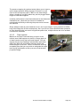
Examples of good hydro system installations ...................................................... 118
11.1.
11.2.
11.3.
11.4.
Good installations.................................................................................................. 118
Poor quality hydro systems .................................................................................... 120
Hydro installations with room for improvement ..................................................... 121
Poor quality turbine install, maintenance and servicing .......................................... 122
12.
Units and conversions ........................................................................................ 123
13.
Warranty and disclaimer .................................................................................... 124
14.
Exclusion and liability ......................................................................................... 125
15.
Contacts ............................................................................................................. 125
16.
Notes ................................................................................................................. 125
17.
Annex I: Jet sizing tables ..................................................................................... 126
18.
Annex II: Common PVC pipe sizes ....................................................................... 126
19.
Annex III Noise measurements ........................................................................... 128
Educational Installations PLT
Notice of Copyright
PowerSpout Installation Manual
Copyright © 2014 All rights reserved
Notice of Trademark
PowerSpout – is a USA registered Trademark
Notice of Company Registration
EcoInnovation – is a NZ Registered Limited Company
© 2014 EcoInnovation Ltd (NZ)
Page 6
Disclaimer
UNLESS SPECIFICALLY AGREED TO IN WRITING, ECOINNOVATION LIMITED:
(a) MAKES NO WARRANTY AS TO THE ACCURACY, SUFFICIENCY OR SUITABILITY
OF ANY TECHNICAL OR OTHER INFORMATION PROVIDED IN ITS MANUAL OR
OTHER DOCUMENTATION.
(b) ASSUMES NO RESPONSIBILITY OR LIABILITY FOR LOSS OR DAMAGE, WHETHER
DIRECT, INDIRECT, CONSEQUENTIAL OR INCIDENTAL, WHICH MIGHT ARISE OUT OF
THE USE OF SUCH INFORMATION. THE USE OF ANY SUCH INFORMATION WILL BE
ENTIRELY AT THE USER’S RISK.
Revisions history
1.1.
Minor text and picture revisions. Jan 2011.
1.2.
Updated PowerSpout versions available and further minor revisions. Feb 2011.
1.3.
Updated PowerSpout versions, added system example photos. Feb 2012.
1.4.
Updated pictures and text and change of product names June 2013. Removal of ME
and GE product lines
1.5.
Updated for CE, FCC and standards compliance August 2013
1.6.
Updated to include TRG and LH turbines in common manual December 2013
1.7.
Edited by H.P. to improve readability and layout, removed wiring diagrams to the
cloud - April 2014
© 2014 EcoInnovation Ltd (NZ)
Page 7
PowerSpout Contact details
Web:
www.powerspout.com
If you cannot find the answers to your questions about our product, renewable
energy systems, or your site's potential in this document or on our website at
www.powerspout.com, please visit www.powerspout.com/faq and submit a question.
We will answer this as quickly as possible, and you will be notified by email when
this occurs.
PowerSpout is a product proudly designed and manufactured by:
EcoInnovation Ltd
671 Kent Road
New Plymouth R.D.1
New Zealand 4371
Web:
www.ecoinnovation.co.nz
If you need to contact EcoInnovation by phone then email first via our web site and
check the local time in NZ if calling from overseas. Business hours are 9:00am to
5:00pm weekdays only. EcoInnovation is closed for up to 3 weeks over the
Christmas break from 24th December.
© 2014 EcoInnovation Ltd (NZ)
Page 8
1. Scope of Application, and Safety
This document is part of the product.
This section addresses safety concerns as required by international standards.
If you are not technically competent, experienced and qualified you should not install this
equipment alone and should engage the services of a suitably trained professional.
Electrical equipment can be installed or operated in such a manner that hazardous
conditions can occur; compliance with this manual does not by itself assure a 100% safe
installation. If the equipment is properly selected and correctly installed and operated
according to this manual, then any such hazards will be minimized.
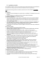
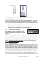
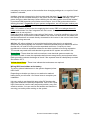
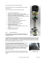
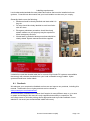
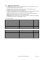
1.1. Turbine serial numbers
As of September 2013 all turbines have identification plates and serial numbers.
IP24 ingress
Model type: PLT,
TRG,
LH,
LH Pro
Serial number:
Rated speed:
rpm
Maximum rpm 3000
IK10 impact
Rated Power:
Watts
Rated
Amps
Short circuit
Head:
m (x10 kPA)
Flow:
Rated volts loaded:
DC
New Zealand – country of origin
Rated volts unloaded:
DC
Date manufactured:
l/s
Mass: < 25 kg
Protective class I - earth connection required
Possible residual voltages - always check first
Klampit
Capacitor discharge time
75
120
240
not fitted
Annual inspection needed refer to manual
Guarantee 2
3
Amps
mins (if fitted)
5 10 years
For example:
You might see 100-7S-2P-S HP F 3061 A as the serial number.
This means you have a 100 series stator, connected 7 Series and 2 Parallel fingers per
phase, High Power rotor upgrade, Filter installed for conducted emission compliance, invoice
number 3061 and other identical units were supplied at the same time labelled A, B, C, D
etc.
If you ever need to query an installation or order spares for a product take a picture of the
identification plate and forward it with your query. The generator code is also engraved on
the back of the PMA stator.
© 2014 EcoInnovation Ltd (NZ)
Page 9
1.2. Installation checklist
The installation shall be carried out by installers with recognized and approved qualifications,
and experience relating to general electrical installations and micro-generators.
To meet good working practices and safety requirements for this installation, the installer
must:
IN GENERAL
check for any transit damage to the product prior to installing it, if damaged it must not be
installed.
connect equipment in compliance with the relevant national standards.
read and comply with this installation manual.
PENSTOCK / PIPELINE
do not install stop valves at pipe intakes, unless there is an air vent to prevent negative
pressure pipe collapse. A stop valve should be fitted at the end of the pipe prior to the
turbine. A sign at this turbine stop valve to “turn off slowly” may be a good reminder to
reduce water hammer effect.
use standard MDPE or PVC pipe. It should be verified that penstocks can withstand 1.5
times the maximum total pressure including surge to which it is subjected, taking into
account the “water hammer” effect produced by the shut-off valve.
if necessary bury the penstock to protect it against rock falls, tree falls, slips, avalanches,
freezing etc.
ELECTRICAL WORK
tighten all electrical connections inside the turbine.
install an earth connection on the exposed metal bulkhead; a labelled earth connection
point is provided - protective class I.
do not connect a DC pole of the turbine to earth - unless local rules require it.
provide a suitable DC rated disconnection device close to the turbine that is clearly
labelled (a 2-pole DC breaker is the good recommended solution).
do not use pluggable connections, hard wiring is required. However “MC4” type
waterproof connectors may be used. If “MC4” type connectors are used, do not open
under load.
protect the supply cable in conduit as per local wiring rules, ensure wiring, insulation,
conductors and routing of all wires of the equipment is suitable for the electrical,
mechanical, thermal and environmental conditions of use.
finger tighten all cable glands to secure supply cable.
ensure that the installation includes the following: voltmeter, ammeter, wattmeter,
pressure gauge and overcurrent protection. Most PWM, MPPT and grid connect
inverters include some basic metering.
if interfacing to the grid do so via a compliant inverter designed for this purpose and
approved by the makers for hydro generation connection.
ensure that the local Distribution Network Owner (DNO) is made aware of the microgenerator installation at, before or within the time allowed after commissioning.
before working on wiring in grid connected or MPPT situations wait 5 minutes for internal
capacitors to discharge. Always check for voltage prior to touching conductors on
equipment that have been recently turned off.
Comply with safety advice in this manual when installing batteries.
COMMISSIONING THE TURBINE
securely fix the turbine base prior to operation.
do not intentionally run turbine unloaded (for other than short duration VOC testing).
do not run turbine at a head significantly above the name plate rating.
in a turbine runaway situation turn off the water supply by closing the water supply
valve(s).
© 2014 EcoInnovation Ltd (NZ)
Page 10
check for excessive noise.
complete turbine testing and commissioning.
ensure that all protective fairing/enclosures are in position after commissioning and prior
to client hand over.
comply with signage requirements as listed in relevant national standards
complete all documentation as required in this manual and local wiring rules.
make relevant notes in the manuals that will be of assistance to future service personal.
train the end owner/user of the turbine in routine care and maintenance of the hydro
system.
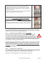
The following safety warning signs are used throughout this manual.
Caution
Risk of electric shock that could result in personal injury or loss of life
Caution
Cautions identify condition or practices that could result in
damage to equipment or personal injury, other than by electric shock.
1.3. CE and FCC Declaration
Refer to http://www.powerspout.com/compliance/ for compliance declarations documentation
and EMC test reports.
PowerSpouts products are CE, FCC and C-tick compliant.
PowerSpout dealers may request to see the Compliance Folder if required by authorities.
1.4. Standards and certification
All PowerSpout turbines have been evaluated against major international standards.
Refer to http://www.powerspout.com/compliance/
1.5. Pre-requisites
All PowerSpout hydro schemes are assumed to be in the following conditions:
Run of river (unless advised otherwise).
Areas free of combustible materials. Assess fire risk of the installation site, and if high
implement extra fire precautions as appropriate. In environments where combustible
materials are present the turbine must be mounted in a concrete or metal enclosure.
Clean river water that will not corrode aluminium parts (sea water is permitted by special
request only).
Temperate climate. Do not install in situations where the pipe line may freeze or in
temperatures below -15°C.
Terrain that can be walked over safely for pipe laying etc. (i.e. no large vertical drops).
The client confirms that the site is unlikely to: slip, have rock falls, flood, earthquake etc.
Where such conditions exist the client has taken appropriate measures.
© 2014 EcoInnovation Ltd (NZ)
Page 11
The client has read manuals, viewed online videos and read installation examples before
starting on this project.
We advise engaging an experienced/qualified installer who has good electrical,
mechanical and plumbing skills.
Flooding risks:
On the upstream side the limit is normally the intake screen (trashrack and the rack
cleaning machine - if installed).
On the downstream side the limit is normally the flooding height that can engulf
equipment.
Where water flows are irregular and in situations where this hydro plant supports solar PV
generation the client needs to supply:
A flow duration curve with an indication of the limiting flows (guaranteed water
supply, irrigation, drinking-water).
Information about their solar PV generation and water flows that exist when sunlight
hours are low.
Specify the extreme water-levels at the intake and at the tail-race in meters.
Specify the power needed at the site in Watts 24/7 or kWhrs/day.
Common MDPE and PVC pipe sizes available locally.
The efficiency and the number of turbines required are determined by the Advanced
Calculation tool: http://www.powerspout.com/calculators/
You must submit this data when you place your order for a PowerSpout turbine.
The client must state:
For direct battery connection the battery voltage 12/24/36/48 etc.
For MPPT units to batteries the model, make and voltage range of the unit (max and
min).
For grid connected units the model, make and voltage range of the inverter (max and
min).
All other information required from the client and data needed by the client are contained in
the advance calculation tool.
Generally the following are not included for clients outside NZ; these might be provided by a
local dealer/supplier/installer:
Civil works
Intake screen
Pipe
Wire
Controller, battery and inverter system or grid connect inverter
Installation service
© 2014 EcoInnovation Ltd (NZ)
Page 12
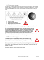
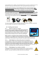
1.6. Fairing safety warnings
The fairing on your PowerSpout turbine forms part of an electrical enclosure and carries the
following warning signs. There are both rotational and electrical hazards present. Turbines
must be turned off at the valve and the electrical breaker turned off prior to removing this
cover.
Electrical hazard
Rotating machinery hazard
Made in New Zealand identification
Recycling identification
Once the turbine has been commissioned, any glazing and fairing need to be fastened in
place with the fixings provided.
PLT turbines have quick release toggle latches. The toggle latches are intended
for commissioning and jet optimisation. Once this is complete permanent fixings
need to be used in addition to the toggle latches. This precaution ensures that
children cannot remove the front cover and be exposed to a rotational hazard.
The Pelton runner spoons are sharp and could cause serious hand injury.
The turbine installer should ensure that the turbine is mounted such that children cannot
reach up under the turbine and be able to touch the spinning rotors.
1.7. Pressurised water pipes
Legislation covering pressurised pipes applies in most countries for pipe
pressures over 10 Bar. The PowerSpout runs at less than 10 Bar in most
approved applications. Check with your local authority if you have any legal
requirement that may concern this installation in your country.
Generally there is little risk at less than 10 Bar pressure. The biggest risk is insecurely
fastened pipe joiners that blow off, with the free end of the pipe hitting people. Securing the
pipe at regular intervals, particularly near the joins, and checking all joiners are tight will
eliminate such risks.
Ensure you install pipe with the correct pressure rating.
© 2014 EcoInnovation Ltd (NZ)
Page 13
1.8. Connecting to the Grid (power network)
PowerSpout PLT/TRG/LH grid-tied options (no batteries required) are available for clients
that are already connected to the grid and have a good water resource close by.
In NZ, Australia and the UK the EnaSolar inverter can be used if the MPP tracking rate is
slowed.www.enasolar.net
Also Aurora wind turbine inverters from Power-One can be used in most global markets
www.power-one.com/
Also Ginlong wind turbine inverters can be used in most global markets
http://ginlong.com/Products/wind_GCI_2G.htm
Please note that SMA have recently withdrawn the Windy Boy range from the market.
WARNING
Operating voltage within a PowerSpout PLT200 disconnected from the grid and
free spinning is normally > 500 V DC. At this voltage contact means
electrocution is likely. DC is much more dangerous than the 230 VAC found in
many European countries and must only be installed or serviced by persons
trained in electrical work.
Please ensure you use a registered electrical worker who is familiar with this type of
equipment and voltages.
You should also seek guidance from your grid operator before attempting to connect.
© 2014 EcoInnovation Ltd (NZ)
Page 14
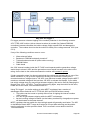
2. Step by step design overview
This section briefly outlines the main choices you will need to make in the design of your
system and ordering the delivery.
2.1. Survey your site
Section 4 describes how to measure the head and flow of your hydro power site. You will
also arrive at a length for the "penstock" or pipeline between the intake and the turbine site,
and the length of the cable to your point of use. Take this information to the online
Advanced Calculator or to a dealer. You will learn how much energy to expect from the
turbine and what size of pipe you will need. Once you have decided the best layout you may
need to get permissions, and take more accurate measurements before proceeding.
2.2. On or off-grid electrical system?
If you are able to connect to the utility grid and it is reliable then we strongly recommend that
you choose an on-grid system without batteries. This will be simpler, cheaper and more
environmentally friendly. Batteries need careful attention, and regular expensive
replacement.
If you are on-grid then you can ignore large parts of this manual that deal with the various
controllers required for battery systems. See section 5.14 for details of how to use a "gridtie" inverter to connect your hydro to the grid so as to save electricity bills.
2.3. Battery voltage choice
12 V batteries were popular for small renewable energy systems in the past, but nowadays
we see 48 V as a more practical choice. However the decision will depend on your needs.
Some very small systems may work better at 12 V because the battery is cheaper to buy
and some of the load equipment may itself be 12 V for example. 24 V offers some of the
advantages of each (and some of the drawbacks). Lower voltage systems are less efficient
on the whole due to higher losses in rectifier and wiring.
If you have an existing battery system then you will probably wish to add the turbine to this
system alongside the solar, wind or engine driven sources of energy that you already use.
2.4. Direct connection or MPPT?
PowerSpout turbines can be connected directly to the battery, and this can often be the
cheapest option. In this case make sure that you provide sufficiently for charge control of
the battery. This can be done using a "diversion load controller" or PWM controller (see
section 5.5.1). But there are drawbacks with direct connection of the turbine to the battery.
PowerSpout recommend connection via Maximum Power Point Tracking devices (controllers
and inverters) that have several advantages: MPPT adjusts voltage automatically for maximum Watts output. This has two
advantages: you tend to get more power, and you don't have to manually tinker with the
turbine to optimise it. (You will still need to adjust the flow to suit available water.).
Higher transmission voltage often results in significant cable cost savings.
Generally fail-safe – in the event of controller failure generation stops so the batteries are
not damaged.
The controller will display (and log) production data.
Precise battery setting of bulk, float, EQ - this is often needed for battery warranty proof.
© 2014 EcoInnovation Ltd (NZ)
Page 15
PowerSpout turbines have been tested for compatibility with a number of MPPT
inverter/controllers and results are available on the website. This list is anticipated to grow as
testing continues so please check the website www.powerspout.com/compatibility for
updates. More information on MPPT regulators is included in the 2014 Technical manual.
2.5. Cable voltage
You need a cable to carry the DC power from your turbine to your point of use. This cable
will waste some power, depending on the current it carries and the size and length of the
wire. A heavier wire will always be more efficient but for long cable runs the cost can
become significant. Using a higher voltage can help to dramatically reduce the size of wire
and the cost. This is one reason for using a 48 V battery rather than 12 V. But with MPPT
you may be able to use higher voltages and make further savings. See section 5.7 for a
discussion of different MPPT controllers and their voltage parameters.
2.6. AC coupling
It's possible to use a 'grid-tie inverter to connect your PowerSpout to an off-grid batterybased inverter's output wiring, if it is suitable for such connections (for example SMA,
Outback, Victron and many others). This option is useful for larger systems with long wire
runs and a high AC power demand. The grid-tie inverter is actually quite similar to the
MPPT controller, except that it feeds the AC side of your power system. Your battery is
charged via the main inverter working backwards when there is surplus energy. This is an
advanced application of the PowerSpout that is not covered fully in this manual but we
mention it for completeness. For more information on AC coupling refer to the 2014
Technical manual.
2.7. Over-voltage protection or not?
Hydro turbines that are not connected to anything that harnesses their power will overspeed
and produce 2-3 times higher voltage than their operating (Maximum Power) voltage. This
"open circuit" voltage or Voc can be a danger to equipment in some cases, although not
always. If you are working at a high cable voltage or your controller has a low Voc rating
then you may need to use one of our Klampit "crowbar protection" circuits to safeguard your
equipment. See section 5.3.3.
2.8. Using surplus energy
Hydro turbines can produce a lot of energy at times when you do not need a lot of electricity
and your batteries may already be full. A diversion load controller will burn this excess off as
heat which can be used to heat water for domestic use.
It is much cheaper in capital cost to store heat in a water tank than it is to use a battery to
provide heating. "On demand" heating should be used with caution. Electric kettles,
induction hobs etc can work well on off-grid renewable energy systems, but the user needs
to monitor the battery voltage prior to use. Discharging the battery excessively and
repeatedly will shorten its life.
MPPT controllers can offer this heating benefit via external load relays, automatically
operated by their auxiliary relays. In some cases it's important that the energy is safely
disposed of, or your batteries or equipment may suffer, but with care you can direct this
energy to useful ends and save burning propane or other fuels.
© 2014 EcoInnovation Ltd (NZ)
Page 16
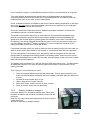
2.9. Optional extras you may wish to order
Check the pricelist for additional items that you may wish to have shipped with your turbine
at no extra shipping cost in many cases. The list includes some useful tools, for example,
the DC current clamp meter, which is indispensable for trouble-shooting battery systems of
all kinds.
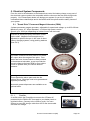
2.9.1.
Bearings
You will need to check the bearings every year and replace if required. (Note that our
warranty terms require annual replacement if automatic grease cans are not installed).
Bearings are inexpensive and easy to replace, see section 9.4. We recommend you hold a
spare set of bearings on the shelf. Some of our Pelton turbines have been running on
original bearings at customer sites for over three years, though we do not recommend that
you do this unless an automatic grease can is fitted.
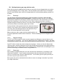
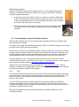
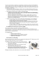
If you purchase 3 auto-grease cans at the same time as your
turbine, all you have to do is replace and activate the grease
can every year; the bearings can then be replaced every 3
years. An annual inspection is still required.
Many customers order a spare shaft and bearing block unit
for quick replacement and minimum downtime. Then the bearings can be changed at your
leisure.
2.9.2.
Manifold fittings
The PLT and TRG models of turbine require pipework and fittings to connect them to your
main pipeline or "penstock". You can buy these items from PowerSpout or locally. It's worth
checking the pricelist to see what can be delivered directly and save effort. (See section 4.9)
The PLT turbine comes with valves and pressure gauge. Unless you buy the discounted
TRG twin pack, camlocks fittings as well as valves and pressure gauge are supplied with the
TRG turbines. All you need to buy is 10m of 50mm ID (2”) flexible hose, and arrange for your
penstock branching to threaded outlets using saddles etc.
2.9.3.
Spare jets
Each turbine in supplied with jets cut to the size that was calculated to your design in the
Advanced Calculator. If your original measurements were accurate then these will work
well, you can also close valves to adjust the flow. You will also get four spare jets that you
can cut to any size (see section 8.3.2).
More spare jets can be ordered with the turbine to save on carriage costs later if you think
you might need them.
© 2014 EcoInnovation Ltd (NZ)
Page 17
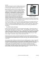
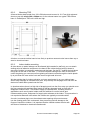
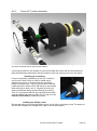
2.9.4.
Adjustable jet options
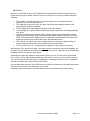
Adjustable spear jets are available (to order) for the PowerSpout
PLT. However, adjustable jets may cause more problems than
they solve and demand for them is generally low.
Adjustable spear valves as shown can be supplied for a surcharge
and operate in the range 3-14mm (circular jet equivalent).
They allow you to quickly adjust the flow rate to suit the stream
flow. However, there are some disadvantages of adjustable spear
valves:
They are more easily blocked by debris in the flow.
The efficiency of the jet (and hence output Watts) is a little
less.
© 2014 EcoInnovation Ltd (NZ)
Page 18
3. Renewable energy from a PowerSpout turbine
Congratulations on your choice of a PowerSpout turbine. This ingenious little device will give
you years of trouble free generation, avoiding the need for expensive generators or power
bills. Not only does the PowerSpout give you renewable energy, it is also made of
predominately recycled materials, making it one of the most eco-friendly micro-hydro
generators available on the global market.
PowerSpout turbines have been shown to achieve up to 60% efficiency and with multiple
units up to 16 kW. You can estimate your generation capacity with our online Advanced
Calculator (www.powerspout.com/calculators/). You will see that our calculations take into
account pipe and cable losses, so we will not fall into the common trap of overstating output.
Most installations exceed our power predictions as we use a conservative calculation model.
See user feedback www.powerspout.com/testimonials/
The manual is intended to guide you through PowerSpout selection, design, assembly1 and
the installation process. Please note from December 2012 all PowerSpout turbines are
shipped fully assembled with only the jet holders removed (in some cases the Smart Drive
PMA may also be removed). This has been made possible due to an improved freight
arrangement with DHL. But the installer is advised to check all internal electrical
connections are tight and familiarise himself with the turbine assembly.
Videos to introduce PowerSpout turbines and demonstrate PowerSpout assembly and
bearing replacement are available via www.powerspout.com. Please note that video clips do
become outdated quickly and may not be updated. Where instructions differ, the latest
written manual (available online) will always be the correct method to follow.
A video on the history of the Smart Drive generator over the last 20 years may interest many
customers.
3.1. How much power will the PowerSpout produce?
3.1.1.
Head and Flow
The generation capacity of your site is determined by the water supply, primarily by the
vertical distance the water falls (head) and how much water flows in a given time (flow rate).
Flow rate at any given time can often be measured by simply watching a bucket filling up
and measuring the time it takes, and the capacity of the bucket. Flow changes around the
year though and you will need to be realistic about how this impacts on the output. Solar PV
is a very good choice to supplement hydro power during drier months on some sites.
For the Pelton and Turgo turbines the head is measured between intake water level and the
turbine jets below. Water exits the turbine at atmospheric pressure back into the stream.
1
The PowerSpout has been fully assembled and tested prior to freight. What little assembly is needed will only take a few minutes.
© 2014 EcoInnovation Ltd (NZ)
Page 19
In the case of the LH turbines, the propeller turbine is normally near to the surface in an
elevated flume. You can measure the head from the intake surface level down to the water
surface in the tailrace below.
3.1.2.
Estimating the power output
A rough estimate of generation potential can be calculated as follows:
Generation (Watts) = head (metres) x flow (litres per second) x 5
Generation (Watts) = head (feet) x flow (gallons per minute) / 10
Standard PowerSpout turbines are rated for up to 1200 W but a special high power (HP)
version is available that is capable of 1.6 kW at 1600 rpm, given suitable water pressure and
flow conditions. Maximum current that the turbine wiring can carry is 32 amps as standard;
an upgrade to 50 amps is available on request for high power low voltage applications (fee
applies).
© 2014 EcoInnovation Ltd (NZ)
Page 20
3.1.3.
Worked example
If for example the head is 20 metres and the flow is 10 litres per second then the power
generated is about 1000 watts or 1 kW continuously (20 x 10 x 5 = 1000). The turbine will
therefore produce 24 kWh of energy per day and over 700 kWh units of energy per month.
This exceeds typical household energy consumption in most countries. If the power output
is only 500 watts then you would get half as many units per month, which would still suffice
in many cases. (The same arithmetic applies to solar PV although obviously that will only
work in daytime hours so that a 1kW PV array is unlikely to produce more than 6 units of
energy per day in summer and may average 4/day or less over a typical the year.)
3.1.4.
Supply and Demand issues
Renewable energy is different from (for example) a diesel generator. In the case of a
generator, you can run your house (or whatever, known as the "load") directly from its AC
output. The governor in the generator will adjust the fuel consumption to meet your needs. If
you run it continuously then you will get through a huge amount of fuel.
In the case of renewable energy, the fuel is free, so you will not want the turbine to reduce its
output to suit the load. You will probably want it to produce as much energy as possible all
the time. That way you make best use of the investment in money and effort that went into
setting up the turbine. The only problem is that at any given moment you will often need
more power than the turbine is producing and you will often need less.
3.2. How to match the constant power supply to our changing demands?
The solution is to store the energy produced by the turbine in a battery, or to feed it into the
electricity grid. When you need more than the turbine can give you then you will draw the
extra from the battery or from the grid. This is how we build a renewable energy "system"
with a PowerSpout turbine (and perhaps also some solar PV panels) and a battery or grid-tie
backup. If the grid is available then this will normally be the more cost-effective way to store
the unused energy.
3.3. What happens if there is not enough water for the turbine?
The flow of water through the PLT or TRG turbines depends on the head of pressure and on
the size and number of jets that direct the water onto the Pelton or turgo runner. If there is
not enough water entering the penstock at the intake to keep this flow supplied then air will
enter and the pipe will gradually empty. This reduces the head and consequently the flow in
the jets is reduced and an equilibrium is found. However this will not produce the best power
output due to reduced head. If the power output is observed to decline then the user
should intervene and adjust the turbine jets to match the new flow. Closing one of the
turbine's valves may be enough to reduce the demand enough that the penstock refills and
full pressure is restored. Power output will be less than full power but at least with a full pipe
the best use is being made of the available water.
The user should check the pressure gauge and make sure that the pipe is always full by
choice of the number and size of jets in use. If the pressure is low then it may be a good
idea to close all the valves and wait until the pipe refills before opening a reduced number of
jets or changing to smaller jets to match the prevailing flow conditions.
On a good site this adjustment may rarely if ever be needed as there will always be sufficient
flow of water to produce full power. But where necessary the PowerSpout can make good
use of partial flows provided that the jets are adjusted to suit.
© 2014 EcoInnovation Ltd (NZ)
Page 21
3.4. How can we be sure of getting the right voltage out of the turbine?
Your turbine will have been designed to produce maximum power at the chosen operating
voltage. Turbine voltage depends on speed. The design process involves predicting the
best rotational speed for the turbine, which depends in turn on the pressure of the water,
which depends on the head you measured.
Accurately measure the head at your site, and use the recommended pipe size, so that
the actual pressure of the water ends up being close to the value that the turbine is designed
for. Every site is different, so the design process is critical and the measurement of head is
key.
3.4.1.
Voltage and turbine speed
The voltage produced by your turbine will vary depending on how fast it is running.
Renewable energy sources such as turbines and PV panels are actually quite volatile in their
voltage. You need a load (for example a battery) connected to keep that voltage stable. If a
turbine or a PV panel is hooked up directly to a battery, it has no choice: its voltage is the
same as the battery voltage. Two things that are connected to each other in parallel must
have the same voltage. If the turbine tries to push its output up to a higher voltage then
there will be a charging current into the battery that holds the turbine voltage down through
its internal impedance. The extra current will raise the battery voltage a little, but the battery
is very stable compared with the turbine or PV. So the battery itself actually governs the
runner speed, by loading (restraining) the turbine when it runs fast enough to produce the
desired voltage.
Your turbine will be designed to work best at the head you have reported for the site and the
voltage of your battery (or controller). We recommend that you opt for an MPPT controller in
the electrical design of the system (later) because this gives more flexibility. The controller
will automatically adjust the voltage (within its operating range) to find the best speed. This
maximises the power. Hence the title Maximum Power Point Tracker.
3.4.2.
Manual optimisation of the turbine
If the voltage is fixed (turbine feeding the battery directly without MPPT) then we can still
manually adjust the speed of the alternator by tweaking a third variable: magnetic field
strength.
The voltage actually depends on several factors: the rpm, the design of the windings in the
stator, and the strength of the magnetism moving past it. By putting spacers behind the
magnet rotor we can move it slightly away from the stator and then the runner will move
faster to create the same voltage. So, if we find that the turbine is a little too slow compared
to it's best speed we add spacers and optimise the output. (see 3.58.4.3 for more on this)
This may be tricky to do and may not achieve the best operating speed and conversion
efficiency for the turbine. It may not be easy to optimise the turbine for all flow conditions,
using packing washers.
One big advantage of MPPT controllers is that they will alter the turbine voltage until they
find the maximum power (corresponding to the maximum speed). So we get the best out of
the turbine under all conditions and we don't have to take it apart and play with spacers to
achieve this.
© 2014 EcoInnovation Ltd (NZ)
Page 22
3.5. Understanding open circuit voltage (Voc)
When there is no current, because the turbine spinning is disconnected, we can measure the
"open circuit voltage" (Voc). The Voc depends directly on the turbine speed in rpm. Double
the speed and you double the Voc. Different turbines will have different Voc/rpm ratio,
depending on the site and the required voltage. But any turbine will have a much higher
voltage when it is running faster off load than it will when working optimally.
Imagine you put your foot on the accelerator/gas pedal in a car when the engine is out of
gear. The rpm will go up quickly and the engine will race. Let in the clutch and the rpm
slows down as the engine comes under load. If you open the valves for the turbine when it
is electrically disconnected then it will overspeed to almost double the best operating speed
for energy production. The Voc will now be much higher than the design operating voltage.
If it is designed to work at 56 volts (to directly charge a 48-volt battery) then the Voc may rise
above 150 volts. This could endanger you if you touch it, and it most likely would kill any
inverter that is designed to connect to a 48-volt battery. So it's very important never to
disconnect the battery when the turbine is running and connected to an off-grid inverter.
In the case of solar PV the Voc is also somewhat higher than the battery voltage, but the
difference is not so huge, and the dangers are less. Most controllers designed for solar PV
will disconnect the PV to control current to the battery. They can withstand the Voc from a
PV array but may be destroyed by the high Voc of the hydro turbine.
Never connect a controller in series between the PowerSpout and the battery unless:
It's an MPPT controller
you have checked rigorously that the Voc will not damage it.
If the battery voltage is 48 V then you will need to either use a protection crowbar (for
example a PLT100C turbine) or you will need to choose a controller with a high enough Voc
rating.
If you intend to run a PLT turbine on a MPPT controller/inverter you must:
Tell us prior to ordering
Report an accurate measure of the head of your system
Check runaway Voc prior to hook up
© 2014 EcoInnovation Ltd (NZ)
Page 23
4. Designing your site layout and choosing your turbine model
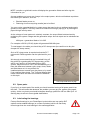
4.1. Measuring Head
You will need to measure the vertical drop in feet or meters (referred to as head or fall). A
map with contours can be useful for initial feasibility study followed by a site survey using the
methods below. It's a good idea to use more than one approach, so you can check
accuracy.
Altimeter - obtain an altimeter accurate to 10 feet (3m), this is good for measuring falls
greater that 70 feet (20m). Take the average of several readings. Some modern hand-held
GPS instruments that are fitted with internal altimeters can read altitude to 1m if the air
pressure is stable during the survey.
Builder’s optical level ("sight level") - measure the fall between intake and turbine in steps as
you progress along the pipe route. This is good for lower falls and it is very accurate. You
can use the height of the spotter's eye level as a unit of measure and move up the slope in a
series of equal steps. Use a helper to mark the spot, or simply keep your eye on that spot
until you are standing on it ready to sight the next one.
Low cost laser level - at dusk or in low light conditions project a horizontal beam and using a
long staff measure the vertical drop, as you progress down alongside the stream. You may
have to repeat this at a few locations.
Pressure gauge - lay a length of small bore plastic pipe or hose, fix a pressure gauge to the
end and measure the pressure of the water with the pipe full. 14.5 psi is 33 feet of fall (100
kPa is 10m of fall). Make sure you clear the line of all air first. This is a very accurate method
and easy to do.
Click here for a recent Home Power article on how to measure the head.
© 2014 EcoInnovation Ltd (NZ)
Page 24
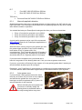
4.2. Measuring Flow
IMPORTANT: "Gallons," "gals," and "gpm" refer to the US Imperial Gallon (3.8 litres),
as opposed to the UK Imperial Gallon.
Try and find a place in the stream where it drops quickly over a rock, place your bucket
below and measure the time to fill it.
At lower flow rates, less than 150 gpm (10 l/s) you need to be accurate in measuring the
flow. If you have a 2 gallon paint pail and the river can fill it in 2 seconds you have 1 gps =
60 gpm, which equates to 227 l/min, 3.8 l/s.
Use the largest possible bucket you can find as the longer it takes to fill the more accurate
your reading will be.
For flows greater than 150gpm try to estimate your flow using a larger bucket in the river and
measure at various places across the river. It will not be as accurate but at higher flows it is
not that critical.
A "notched weir" is useful for monitoring flow over time as it can be used to take quick
readings on a regular basis, but it takes some effort to construct.
Click here for a recent Home Power article on how to measure flow rate.
4.3. Choosing the correct turbine for your site
Different sites will need different PowerSpout models depending on the head and flow.
All PowerSpout products are named with one of the following model abbreviations:
PLT
(PeLTon turbine)
TRG
(TuRGo turbine)
TRG and PLT model turbines are connected to pressurised pipework that feed water
through jets towards the turbine runner, spinning the runner and hence the generator,
which generates electricity. These are normally referred to as "impulse turbines".
LH & LH Pro
(Low Head propeller turbine)
LH model turbines direct the water through guide vanes that spirals on to a propeller
shaped runner, causing it to spin. These are normally referred to as "reaction turbines".
The turbine sits close to the intake water surface with the alternator on a stalk above
flood levels. Water is actually driven by suction created by the weight of water in the
draft tube below the turbine. The head is measured from the water surface at the
turbine to the water surface of the tail race where the draft tube discharges.
© 2014 EcoInnovation Ltd (NZ)
Page 25
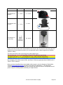
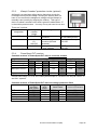
Version
Head (m)
Flow (l/s)
PowerSpout PLT
(Pelton)
3 – 130 m
0.1 – 10 l/s
PowerSpout TRG
(Turgo)
2 – 30 m
PowerSpout LH
(Low Head)
1–5
metres
(below
turbine in
draft tube)
photo
8 – 16 l/s
25 – 56 l/s
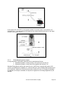
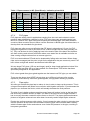
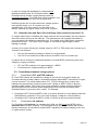
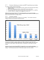
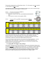
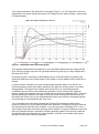
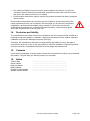
When you have found out the head and flow rate at your site, the chart on the next page will
quickly tell you the maximum power you can generate (refer to black angled lines indicate
100W to 12kW).
The coloured zones refer to the range for each product type:
The red lines are 1, 2, 5, 10 PowerSpout Pelton (PLT) turbines respectively
The yellow lines are 1, 2, 5, 10 PowerSpout Turgo (TRG) turbines respectively
The blue lines are 1, 2, 5, 10 PowerSpout Low Head (LH) turbines respectively
For example a site with a head of 20m, and flow of 10l/s can generate about 1000 W with 1
TRG or 2 PLT turbines.
Once you have identified the most suitable turbine type(s), use the Advanced Calculation
Tools at www.powerspout.com to perform accurate site calculations. The Advanced
Calculator will help you find the best sizes of pipe and cable for the site, and predict the net
power output for each possible size that you might choose.
© 2014 EcoInnovation Ltd (NZ)
Page 26
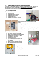
4.4. Siting your PowerSpout turbine
Some tips for locating a good site for your turbine include:
4.4.1.
Choose a place that is accessible.
If necessary make steps and put in rope handrails to ensure that your turbine can
be accessed safely.
4.4.2.
Choose a site that has the most fall
You should position the PowerSpout to obtain the greatest fall (head of pressure) possible
with the shortest length of pipe. If it makes the cable unacceptably long then look at using
MPPT to raise the cable voltage.
In many situations it is possible to divert the pipeline closer to the home to provide a
pressurised water supply as well as electrical generation. In combined power and water
schemes electric power is often employed to UV treat the water. In some cases the
PowerSpout is only used for UV treatment at remote water storage tanks for small
communities. This is often more cost effective that installing grid power to the site.
© 2014 EcoInnovation Ltd (NZ)
Page 27
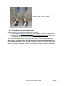
4.4.3.
Keep your PLT/TRG turbine as low as possible
Maximise the head, but do ensure that it is above maximum river flood level.
Your PLT/TRG turbine should also be positioned at least 50-100 mm above ground height to
allow exhaust water to escape. Choose a site where the exhaust water can be returned
back to the river cleanly.
4.4.4.
Place it as close to your battery bank or point of grid connection as
possible,
The cost of the cable is important, although cost depends on the chosen voltage. A low
cable voltage means that a short, heavy cable is desirable.
The distance between your turbine and batteries has a significant bearing upon the cable
size required. To keep cable size (and hence cost2) down we usually recommend that offgrid clients who are not using MPPT choose 48-volt battery systems rather than lower
voltage. In such cases we generate a voltage at the turbine about 5% higher that your
battery voltage (due to voltage sag in the cable). Turbine sites up to 500 m away are often
economically viable using 2-core aluminium cable.
Using an MPPT controller offers the opportunity to reduce the cost of the cable by
generating at a higher voltage. For example the PowerSpout PLT80 generates and
transmits at about 80 V DC cable voltage to a Midnight Classic 250 MPPT controller close to
your battery bank. If you have a 24 V DC battery bank this can reduce the cost of the cable
by up to 80%. The controller changes the voltage to suit your 12/24/48 V DC battery bank.
One benefit of this approach is that existing 12/24 V DC systems can be cost effectively
integrated with the PowerSpout PLT/TRG/LH. For example, solar PV systems can struggle
in winter time when you have viable stream flows. Adding a PowerSpout to your system can
often eliminate the need for fossil fuel generation support, as solar and hydro resources tend
to complement each other.
4.4.5.
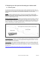
Hydro turbines do make some noise, so keep them at least 30 m from
your home.
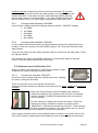
Some clients have installed turbines too close to their homes. Measured noise levels are
listed section 19
Generally the higher the head the more noise from the unit. At our test site at 160m head
and 1.6 kW you can talk normally standing by the turbine, but you are very aware it is there.
You can just hear it at 30-40m away. It sounds like a washing machine in spin.
On low head sites less than 10m (30ft) the river is likely to make more noise than the turbine.
A turbine can be closer to a dwelling in such cases. Vegetation around the turbine will
dramatically reduce the distance that noise carries.
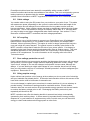
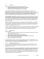
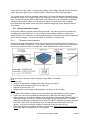
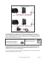
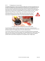
4.5. Connecting two small streams into one PowerSpout
We are often asked if two small streams can be piped into a common turbine. This is not
recommended, unless the head and pipe friction losses for each pipe are very similar.
Generally we would advise two turbines, one for each site. The electrical output of both
could then be joined together into a common supply cable, but only for PLY/TRG 12/24/48
VDC turbines. If you want to use MPPT then you will need a wire for each turbine.
2
EcoInnovation holds considerable stocks of cable at very good prices for our NZ customers
© 2014 EcoInnovation Ltd (NZ)
Page 28
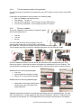
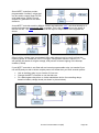
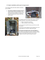
Dual install, one unit runs on 30m (98 ft)
head the other 10m (33 ft) head
4.6. PowerSpout site data requirements
In order to assess your hydro site potential you can either
Visit our web site www.powerspout.com and complete the advanced calculator, or
Complete the table below and email it to [email protected] we will reply
promptly with the best hydro option available for your site.
Your turbine will be designed for the site data you supply above. If you operate it on a
different site, the output power will differ and not necessarily match the prediction of
the advanced calculator. A new generator core may be required to obtain the best results
in such cases. If you intend to run your turbine over a wide range of flow rates, you need to
state this at the time of ordering. A different generator core can be supplied for an additional
charge.
© 2014 EcoInnovation Ltd (NZ)
Page 29
Hydro site data required for PowerSpout product manufacture
Question
PLT, TRG,
PowerSpout turbine type
LH or LH Pro
Have you read the PowerSpout product manuals?
Yes/No
You must do so before placing an order
Head at site (vertical drop/fall of pipe)
Pipe or flume length required to get fall
Supply pipe inside diameter if installed
Do you want us to advise your pipe size?
Yes / No
Flow available at intake
What is the cable length from turbine to the power
shed?
If cable is installed, what size is it?
Do you want us to advise cable size?
Yes / No
For MPPT applications state your battery voltage
12/24/48
For MPPT applications state the controller make
and model
For Grid connect applications state the inverter
make and model you intend to use
How much power do you require at your site on
average?
Units
m or ft
m or ft
mm or inch
l/sec or gal/min
m or ft
mm2 or sq inches
Volts
kWhrs/day
Additional Hydro site data required for PowerSpout LH and LH Pro manufacture
Questions
Units
Can a vertical draft tube be installed?
Yes / No
Can you buy 200mm and 250mm OD thin-walled
Yes / No
PVC pipes locally to make the draft tube?
If No above then state the inside and outside
Flared end ID
____ mm or Inch
dimensions of the PVC pipes you can obtain of a
Flared end OD
____ mm or Inch
similar size. State these dimensions for both the
plain and flared ends on the pipe.
Plain end ID
____ mm or Inch
(read LH Installation manual for more information)
Plain end OD
____ mm or Inch
4.7. The Penstock
The online advanced calculator at www.powerspout.com/calculators/ will have advised the
appropriate internal diameter (ID) of pipe for the "penstock" or pipeline, based on the site
data you entered. You should position the PowerSpout to obtain the greatest fall possible in
the shortest distance.
For initial feasibility you can use a map and/or gps to survey penstock options. When you
have chosen the locations for the intake and the turbine, measure the pipe length using a
long tape or wheel, be accurate, as this information will be required to buy the pipe and it’s
important to get it right.
Try to lay the pipe to avoid high spots in the line that might trap air bubbles. Use a level to
check that it is always graded downward. If a high spot is unavoidable you will need to place
a bleed valve at the highest point in the pipeline to purge air. Air locks in the line will
significantly affect the power output of the turbine. The longer the penstock the more of a
problem this tends to be. Penstocks over 1 km long can be problematic if there are many
high spots trapping air. Automatic bleed valves may be useful in such cases.
© 2014 EcoInnovation Ltd (NZ)
Page 30
4.7.1.
Pipe sizes
Pipe sizes commonly used with our hydro products include:
PVC for larger sizes based on OD (110-300 mm normally)
MDPE or HDPE based on OD (50-110 mm normally)
LDPE based on ID in NZ/AUS (40-50 mm normally)
Many different standards exist for pipe sizes which vary depending on industry and
geographical area. The pipe size designation normally includes two numbers - one that
indicates the outside diameter (OD) and the other that indicates the wall thickness. American
pipes were categorized by inside diameter (ID) in the past but this was abandoned to
improve compatibility with pipe fittings and joiners that usually fit the OD of the pipe.
Inside diameter is critical for calculation of pipe friction loss since a variation of as little as
1 mm can have a very significant effect on the output power of the turbine. Take care with
which diameter you are referring to since if calculations are done based on pipe ID and the
pipe is then purchased based on OD your turbine will generate less power than predicted
due to increased pipe friction. Pipes below 40 mm ID cannot normally be used as friction
losses are too high.
Pipes have different pressure ratings so a given pipe size is often available in a number of
pressure ratings. These different ratings are achieved by either altering the material grade
(Low, Medium or High Density PE) or increasing the pipe wall thickness. The OD is kept
constant so standard pipe joiners still fit.
In NZ for example, polyethylene (PE) pipes can be purchased from 35 m (50 psi) head rating
to 160 m (230 psi) head rating. Some sizes are based on ID but most are based on OD
sizing, so be careful and double check with your supplier the OD and ID of the pipe.
4.7.2.
Pipe material
A pipe should be:
Equal to or larger than recommended from the calculations that specified the output
power (Watts) of your turbine.
Cost effective, tough and durable for 20-50 years.
Able to handle the static pressure of the head of water.
Able to handle the running head x a factor 1.5 to allow for water hammer
Easy to lay and bend around obstacles.
Able to be purchased in long lengths.
The PowerSpout PLT has a maximum running head rating of 130 m and allowing for up to
25% pipe friction loss, sites up to 160 m static head can be used. A higher water head can
be used successfully but with reduced lifespan and warranty.
4.7.3.
MDPE and HDPE pipes
The range and the fact that they are durable, low cost and commonly available in a wide
range of sizes, pressure ratings and lengths makes PE pipes the obvious choice for the
PowerSpout PLT turbines.
Remember that you can vary the pipe pressure rating to minimise costs. For example, if you
have a 100 m head you start with low grade (50 psi, 3.5 bar) pipe, a length of 6 bar, then 9
bar and finally 12 bar. Laying 12 bar pipe all the way would almost double the cost of the
pipeline. If you do this the pipe ID will change, so the calculated output may not be correct.
To avoid disappointment use the smallest pipe ID in the online calculator and your turbine
should generate a little more than predicted.
© 2014 EcoInnovation Ltd (NZ)
Page 31
Table 1. Pipes common in NZ (Rural Direct)– indicative prices 2014
Pipe
OD
Pipe
ID
mm
57
mm
Material
Pressure Pressure Pressure Pressure Approx Approx
rating
rating
rating
rating
cost/m cost/ft
PSI
M
MDPE
102
70
63
53
HDPE
131
90
63
50
HDPE
174
120
75
65
HDPE
116
80
90
79
HDPE
116
80
110
94
HDPE
116
80
Bold indicates the change from ID to OD sizing
4.7.4.
50
kPa
700
900
1200
800
800
800
Bar
7
9
12
8
8
8
NZ$
4.00
5.00
7.00
6.80
8.60
11.50
US$
1.05
1.30
1.80
1.75
2.25
3.00
PVC pipes
PVC pipes are widely used in applications ranging from low cost road culverts to mains
pressure water distribution networks in cities. PVC pipe sizes vary around the world (see
Annex II: Common PVC pipe sizes) and frequently the available pipe sizes differ between
countries. Most countries seem to either use the American or British pipe size dimensions, or
develop their own standards for pipe sizes.
PVC pipes are often more cost effective than PE pipes in sizes above 110 mm. As PVC
pipes glue together the cost to join them is low, so short lengths can be used (normally 4-6
m). They can be bent in-situ by applying heat to the tension side of the bend. We therefore
see them mainly used at lower head sites where more water flow is available and often on
sites running multiple turbines from a common pipe line.
PVC is not as durable as PE and can be shattered by falling rocks and trees. Where these
risks can be managed and the price is right for the application they are commonly used. PVC
left in direct sunlight will weaken and become brittle with age.
We see larger PVC pipes (150 mm and larger) used for lower head applications below 30 m
and often with less than 200 m of pipe needed. Our PowerSpout TRG turbine has been
specifically designed for this application.
PVC culvert grade farm pipes glued together are the lowest cost PVC pipe you can obtain.
There are also larger sized HDPE culvert pipes up to 450 mm but these often require
expensive joiners as they cannot be glued together, though plastic welding is possible.
4.7.5.
Pipe myths
We often get told that the pipe has to reduce in size in order to keep up the pressure. This is
a huge misconception and arises from confusion with irrigation schemes. If you decrease the
pipe size you increase the friction, which will actually decrease the final pressure.
The pipe for an irrigation scheme supplying many farms will reduce in size as the last farm
has to convey a smaller amount of water. The start of the pipe has to be larger because it
has to convey the water needed for all the farms on the line. The pipe myth arises because
pictures of irrigation schemes have often been incorrectly used to depict hydro schemes.
People also confuse pressure with velocity; if you increase the pipe velocity by reducing pipe
size the pressure at the turbine will decrease. Reducing pipe size increases water velocity,
which increases pipe friction and reduces even further the pressure in the pipe, resulting in
less power generation.
© 2014 EcoInnovation Ltd (NZ)
Page 32
If the penstock simply discharges "full bore" (for example, to flush out sediment) then the
flow will be large, and there will be no pressure left. Pressure is all used up in pipe friction.
Normally the turbine uses jets to restrict the flow and convert the pressure into velocity to
drive the runner. The flow in the penstock will be controlled by the size(s) of jet(s) that you
use in your turbine(s). Larger jets will demand more flow, which will in turn create more
friction loss, and may reduce the pressure at the turbine. Smaller jets will minimise the flow
and the pressure will be slightly higher. Using a small bore jet may result in higher pressure
(due to lower flow rate) but using a smaller bore pipe will not, as it simply increases the
friction.
Another common myth is that pipe bends are the cause of a lot of penstock losses. In reality,
relative to the long hydro penstock, a few correctly sized bends will make no noticeable
difference as most friction loss is caused by the length of the penstock.
4.7.6.
Laying and securing pipes
When laying the pipe try to do the following:
Install a good strong intake structure.
Secure the pipe against flash floods during the installation process.
Obtain a good fall in the first 5-10 m of pipe.
Lay the pipe on a gradual, always descending line where possible.
Keep the number of high points to a minimum and vent these to avoid air locks,
pressure rises and pressure drops.
Avoid siphon systems if possible.
Once the pipe is in position, securely fasten the pipe line to rocks, trees, or ground
anchors to prevent it moving down the incline or being washed away in flood events.
4.7.7.
Penstock valves
You may wish to install a valve below the intake, but this is rarely useful. If you do install a
valve at the top end of the penstock then the weight of water below will cause a vacuum that
may collapse your pipe or draw debris into it. It is good practice to fit a vent pipe just below
any such valve so the penstock can drain. This vent often helps air to escape while the
penstock is filling.
The turbine comes with valves that control the individual jets, but you may also wish to put a
larger valve on the penstock just prior to the manifold. Closing this valve allows you to work
on the manifold without draining the penstock. It also means that the penstock can be filled
and bled of air in advance of installing and commissioning the turbine itself. The air can take
time to find its way out via the intake and vents fitted.
You may need bleed valves at high points if the penstock slope is not continuous. These are
only used to remove air and can be closed during operation.
Finally you may wish to install a flush valve at the bottom end of the penstock so that you
can flush out sediment.
None of these valves are always essential - each has possible merits.
© 2014 EcoInnovation Ltd (NZ)
Page 33
4.7.8.
Pipe thrust blocks
On larger hydro schemes using rigid pipes,
thrust pads and anchor blocks may be
required to prevent movement of the pipe
work. On these larger hydro schemes
professional engineering advice must be
engaged to calculate the supports needed.
4.8. Intake design and placement
The intake for a PLT or TRG turbine should be positioned at the base of a small set of rapids
typically no more than 300-500mm high (to allow room for a sloping intake screen as shown
below). Water flows over the top of the screen falling into the chamber below that feeds the
supply line. Leaves and twigs are washed away with surplus water preventing the intake
from blocking.
Intakes often need to be made to suit each site. The examples below illustrate different ways
to do the same job. The picture of the angled guides and screen is the recommended way to
make a good strong maintenance free intake screen. You must ensure you securely attach
the intake screen to the riverbed by driving galvanized stakes into the ground or attaching to
large boulders with brackets, bolts and cement.
Angled screen
Flat screen in road culvert
Stainless steel perforated tube
Perforated galvanized cable tray intake
© 2014 EcoInnovation Ltd (NZ)
Page 34
Angled guides and screen - the best!
Perforated box in concrete
Commercial intake on road culvert
Perforated box
Stainless woven tube from scrap yard
Intake made from stainless steel scrap
Intake screens such as these can be purchased. However, they are easy enough to make to
suit your site. You can use a stainless steel mesh and a plywood box, make sure you
support the screen from behind with stainless steel rods/frame otherwise during floods the
mesh will be pushed in. A fine, smooth stainless steel gauze with a hole size typically 1-3mm
should then be placed over the stronger frame. This smooth gauze will allow debris to slide
off easily and prevent small aquatic life forms from entering the pipe line.
© 2014 EcoInnovation Ltd (NZ)
Page 35
Some ideas for intakes made from scrap stainless steel components
4.8.1.
Water usage with minimum impact on the environment
Micro-hydro systems may potentially affect:
Plants and fish in the water.
Plants and animals beside the water.
Stream banks and surrounding land.
You must check with your local authorities to see if you need to obtain consent either to build
any structures or to take/return water from a waterway. The impact of your system on stream
ecology will usually be considered during this process. EcoInnovation have some consent
application examples for NZ that we can email you that might help in your application.
Most micro-hydro systems divert a fraction of the main water flow through an intake screen
to the generator. A good intake will lead to negligible erosion and the screen will minimize
the chance of fish, leaves, etc entering the supply pipe. Taking less than 50% of the
minimum seasonal flow rate in your water source means there is no impediment to fish
moving up or down stream and hence gives aquatic life a better chance to survive.
You should take care to ensure that the exhaust water from the turbine can return to the river
without scouring the bank of your waterway. Line the bank with concrete, timber or plastic
sheet as required. Some systems utilise the exhaust water for irrigation, allowing the water
to percolate through the soil before returning to the waterway.
Good example showing:
Concreted river bank
Timber boards to prevent river bed
erosion
© 2014 EcoInnovation Ltd (NZ)
Page 36
4.9. Turbine "manifold" connecting options PLT and TRG
The manifold is the system of pipes that connects your penstock to your turbine jets.
The penstock is what we call the main pipeline from the intake.
1-5+ hydro turbines are commonly connected to a single penstock. It is helpful if at the end
of the penstock there is a large valve so the pipe can be flushed to purge sand/silt. Turbine
manifold pipes are often branched off the main run before this flush valve.
This section covers different ways that turbines can be connected in a cost effective manner.
Parts for many of these options can be ordered at the same time as you order your
PowerSpout turbine.
4.9.1.
Connecting your pipe to the PowerSpout
The ball valves supplied have either 2” female BSP threads or (for the USA and other
countries that use NPT threads) a 2” BSP thread on the jet side and 2” NPT thread on the
other side. Customers in the USA can buy NPT threaded fittings locally. (PowerSpout can
also supply PVC manifolds for our PLT turbines with 2” BSP/NPT threads, see below.)
Penstock pipe fittings must be bought separately, as every site is different. For larger pipe
sizes we have pipe joiners available for purchase that fit onto MDPE and HDPE pipe with the
following OD: 63 mm (2.5”), 75 mm (3”), 90 mm (3.5”) and 110 mm (4.5”). These larger
fittings if needed are supplied for an extra charge.
4.9.2.
Recommended manifold pipe sizes
For flows up to 3l/s per jet, manifold pipe size ID should be 50mm or larger
For flows up to 5l/s per jet, manifold pipe size ID should be 65mm or larger
The table below indicated the power loss in Watts per metre of pipe.
(Also an elbow or Tee fitting equals roughly 2 more metres of pipe.
Such losses tend to be negligible on a penstock, but important on small-bore manifolds.)
Flow l/s
1
2
3
4
5
4.9.3.
Pipe bore in mm
40
50
1.8
0.6
3.6
1.2
5.4
1.8
7.2
2.5
9
3
65
0.2
0.35
0.5
0.7
0.9
90
0.04
0.07
0.1
0.15
0.2
Quick connections
The ability to quickly remove the turbine from the pipework is important so that
turbines can be easily serviced.
There are 2 common ways that a quick connection can be made:
Plastic Camlocks 50mm (2”)
Camlocks with flexible pipes (hoses) are more suited to
lower head sites of 60m and less.
PVC mac-unions (for rigid pipes)
PVC mac-unions are rated for heads up to 160m.
© 2014 EcoInnovation Ltd (NZ)
Page 37
4.9.4.
The connections made to the penstock
You will need up to 2 penstock connections for every PLT turbine, and up to 4 for every TRG
turbine.
Connection to the penstock can be made in the following ways:
Bolt over saddles and flexible hoses
Pipe fittings - T’s and Y’s
Our PVC 4 jet manifold – for PVC pipes and the TRG turbine
Our PVC 2 jet manifold – for PVC pipes and the PLT turbine
4.9.5.
Bolt over saddles
These are available to order with your turbine for pipes
with outside diameters of:
160 mm
110 mm
90 mm
You can install as many as are needed. They are
double sided so provide 2 x 50mm BSP male threads
per saddle set. Pictures below show how you install them on your pipes.
These saddles can also be used for making a large pipe vent just after the intake.
Once the saddles are fitted, use the valves and camlocks (often supplied with your TRG
turbine) as shown. Note that the valves are fitted to the saddle and not to the turbines. This
ensures that the turbines can be easily removed for servicing leaving the off valves in place.
Saddles have the following advantages:
Low cost
Less freight bulk and light in weight
Easy to fit, no special tools needed
Saddles have the following disadvantage:
Sharp take-off so higher fitting losses,
meaning they are not suited to low
head, high flows
Saddles connected to turbines via camlocks and flexible pipes suit heads between 10m and
60m, and flows up to 3 l/s per turbine jet with 50mm ID pipework. Most PLT turbines can be
connected in this manner. For TRG applications the next option should also be considered.
© 2014 EcoInnovation Ltd (NZ)
Page 38
4.9.6.
Pipe fittings - Y’s
PVC “Y” fittings suit higher flow TRG sites that commonly use 160 or 200mm OD PVC pipes.
PowerSpout can supply this optional PVC manifold kit as shown below. The end user has to
glue it together. It suits sites in the head range 5-20m and flows up to 4 l/s per jet with 50mm
ID pipework. For sites in the 2-5m range, 3” camlocks and flexible pipe connections should
be considered. Manifold losses are more critical as there is little head to start with, and such
losses can result in reduced performance.
The TRG PVC manifold kit comprises:
1 x 200-160mm PVC reducer
2 x 160mm joiner pipes (120mm long)
2 x 160mm to 110mm double “Y” fittings
1 x 160mm screw end plug
4 x 110x75mm reducers
4 x 75x65mm reducers
4 x 65mm joiner pipes (100mm long)
4 x 65mm to 2” BSP male fittings
4 x 2” BSP ball valves – often supplied with your turbine
4 x 2” BSP male camlocks and hose-tail fittings
When all glued together it looks like the picture above.
Your TRG turbine can be positioned as shown and then hooked up with flexible pipes.
Unless you buy the discounted TRG twin pack, camlocks fittings and valves are supplied
with the turbines. All you need to buy is 10m of 50mm ID (2”) flexible hose.
A common comment from dealers and clients is that flexible pipe manifolds need supports
and are rather unsightly.
We tend to agree, but note they are:
Cost effective
Easy to align - With flexible hoses you can make fine adjustments to the nozzle by
manipulating the hose itself during optimisation at set-up and then securing it in this
position.
Easy to remove
Use fewer elbows, so have lower losses for a given ID.
© 2014 EcoInnovation Ltd (NZ)
Page 39
4.9.7.
PVC 4 jet manifold – for PVC pipes and the
TRG turbine
A PVC manifold option is available to special order, as
shown. These are tricky to put together and final gluing must
be done by the end client. They do give a very clean and
professional look and some clients will prefer this option.
4.9.8.
PVC manifolds for our PLT turbines
PowerSpout can supply PVC manifolds for our PLT
turbines with either 2” BSP/NPT threads or 2.5” BSP
threads. As PVC sizes are often different from one
country to another, using a common thread size as a
connection method is often the best way to avoid
problems on site.
The picture shows two turbines connected via PVC
manifolds to a mac-union and then to the black
plastic MDPE pipe via a threaded connection.
The penstock was separated into 2 lines prior to feeding each manifold by using a T and 90
degree elbows.
4.9.9.
Pipe fittings - T’s and 90 degree elbows
For many sites HDPE pipe fittings can be used to
build a manifold.
You are likely to need
T’s
90 degree elbows
Joiners
Thread adaptors
If you are installing just 1-2 PLT turbines then it is
likely you are using 63-110 mm OD MDPE pipe.
Offcuts of this pipe with some fittings can be used to
make a low cost splitter manifold combined with a
factory made PVC manifold as shown.
All the bends in the manifold
opposite do not result in significant
losses since the penstock pipe is
80mm ID; this splits into 2x80mm ID
pipes, then this is split again into
2x65mm ID PVC pipes. This means
that the water velocity in the PVC
pipes is 1/3 of that in the penstock,
so losses will be very low. We will
show you how to check for
penstock losses later with a
pressure gauge.
© 2014 EcoInnovation Ltd (NZ)
Page 40
4.9.10.
Mock up your manifold off-site first
You will save a lot of time if you mock up your manifold and exhaust water collection off site
where it is easier to work. This picture shows 2 x PLT100C turbines trial fitted off site prior to
carrying all the parts 800m into dense forest. Note the mac unions so that the turbines can
be easily removed.
4.9.11.
Other manifold options
There are many possible manifold solutions; there are some pictures below to give you ideas
for your situation.
4.9.12.
Measuring pressure in your pipe and manifold
Pressure losses in your Penstock and manifold are typically in the range 5-33%, with a 10%
loss typical (used as the default in the online calculator). It is very helpful if you can measure
both the static and dynamic pressure at the end on the Penstock and just prior to the turbine
jets. From these readings you are then able to determine the losses in the Penstock and the
losses in the manifold. All PowerSpout turbines (other than discounted twin packs) include a
pressure gauge.
© 2014 EcoInnovation Ltd (NZ)
Page 41
The pressure tapping kit (optional extra) allows you to insert a
quick release pressure fitting at points of interest. You will
need to drill and tap the pipes ¼ BSP to use these fittings.
When a reading is not being taken they can be plugged with a
length of solid tube supplied.
If turbine performance is less than estimated in the Advanced
Calculation tool, check that you have not installed an
undersized manifold by measuring the pressure loss across
the manifold.
Sharp elbows create as much head loss as a 1-2m of pipe length. If your penstock is 1000m
long a few fittings are of little consequence, but if you are on a short small diameter penstock
at a low head then this can result in significant power loss, multiple elbows are to be avoided
in small bore manifolds.
4.9.13.
Pipe supports
Make sure the pipe is secured firmly just prior to the
turbine (note metal supports in picture). A large pipe full
of water can be heavy and may need support. You can
support the pipe by installing a wooden/steel post either
side of the pipe with a horizontal member above and
below the pipe to secure it. Bear in mind when securing
moveable pipes that you may wish to manipulate the pipe
itself during optimisation at set-up so as to find the best
jet position/angle.
© 2014 EcoInnovation Ltd (NZ)
Page 42
5. Electrical System Components
From the coils in the alternator to the heaters that control the battery charge, every part of
the electrical system needs to be compatible with the others so that the whole thing works
properly. Your PowerSpout dealer can design your system for you but it is helpful to
understand these relationships and to be familiar with the options and the safety issues of
your system.
5.1. "Smart Drive" Permanent Magnet Alternator (PMA)
3-phase permanent magnet generator, adjustable for speed and voltage, up to 80% efficient.
Maximum power: 0.7 W/rpm standard, 1.0 W/rpm high power version
Speed: up to 1600 rpm depending on turbine runner and site head.
Magnet rotor
The rotor is directly driven by the turbine runner
via the shaft. Magnetic field strength can be
adjusted to optimise the rpm in the case of direct
battery-charging systems, using packing washers
(See 8.4.3)
Stator
The stator contains coils that produce a 3-phase
AC output when the magnet rotor spins. Your
stator has been chosen based on data provided
in the advanced calculator, so as to provide the
correct voltage at the best RPM for your turbine
runner to operate with your chosen head of
pressure.
Bearing block and shaft
This supports the above parts and also the
turbine runner. Bearings need to be greased and
replaced periodically.
Automatic grease dispensers are available as an
optional extra.
5.1.1.
Rectifier
A rectifier within the PowerSpout converts the 3-Phase AC
produced by the PMA to DC for supply to your battery bank or
grid-tied inverter. Contrary to the common myth, it is more
efficient to send DC along a cable than AC for the same cable
size and rms voltage.
© 2014 EcoInnovation Ltd (NZ)
Page 43
In order to comply with standards for conducted and
radiated emission noise, the 3-Phase rectifier in your
PowerSpout may include a noise filtering module for
conducted emissions. This EMC filter in only included if your
turbine was ordered for a grid-connect application.
Rectifiers get hot due to losses and lower voltage systems
have greater losses. In a 12 V system you lose
approximately 10% of the energy you generate in the
rectifier, whereas this figure is only 3% for a 48 V system.
5.2. Unloaded rpm and Open Circuit Voltage (Voc) revisited (see also 3.5)
In a hydro turbine that is unloaded (the output wires are left unconnected), the rotor reaches
almost the same velocity as the water jet. The resultant rpm can be easily calculated for
your site data by the advanced calculation tool. The voltage of any PMA when unloaded is
proportional its rpm. This "open circuit voltage" or Voc can be high enough to cause
damage or danger.
In theory (if we ignore friction) the voltage output of a PLT or TRG turbine can increase up to
4 times for two reasons:
The rpm theoretically increases to almost 2 x normal speed
The Voc for an Smart Drive PMA is almost 2 x MPPV even at constant rpm
In practice due to friction the relationship between Voc and MPPV (maximum power point
voltage) is roughly as follows:
PLT and TRG turbines Vo is approximately 3 x MPPV
LH turbines Voc is approximately 2 x MPPV
5.3. PowerSpout standard voltage options
5.3.1.
PowerSpout PLT and TRG turbines
PLT and TRG turbines are identified by voltage to suit the site and system design e.g.
connected directly to battery banks, connected to battery-based MPPT controllers or to gridconnect inverters. The turbine abbreviation (PLT, TRG) is followed by a number that
indicates the approximate "maximum power point" voltage or MPPV, which is also the
operating cable voltage. This will be close to the voltage the turbine produces when the
speed is optimised for maximum power depending on how accurate the design data
(estimated head, etc) proves to be in reality. For example:
PowerSpout PLT 28 has an MPPV of 28 V (connects directly to 24-volt battery bank with
PWM diversion controller). 28 V is the "bulk charging" voltage for a 24-volt battery.
PowerSpout PLT 200 has an MPPV of 200 V (connect to grid via grid-tied inverter)
5.3.2.
PowerSpout LH turbines
For PowerSpout LH turbines, for example the LH200, the 200 is not the MPPV but the
maximum Voc at turbine runaway. This is because there are no LH turbines that connect
directly to batteries. All LH turbines require MPPT regulation for battery charging or the use
of a grid connect inverter.
© 2014 EcoInnovation Ltd (NZ)
Page 44
5.3.3.
Klampit "crowbar" protection circuits (optional)
A Klampit is a proprietary safety device that short circuits the
PowerSpout at a pre-set voltage. Shorting the turbine does not
harm it, but removes the dangerous voltage until the Klampit is
manually reset (usually by stopping the turbine). This type of
device is called a crowbar circuit and is given the abbreviation “C”
in the turbine product name. You may or may not need to use one.
There are 3 options:
PLT/TRG Turbine
designation
56C
Klampit
crowbar
voltage
75 VDC
statutory significance
Used with
ELV in many
direct connection to
countries
48-volt battery at ELV
100C
120 VDC
ELV in some
MPPT controllers up to
Or
countries (NZ and
150 VDC
140 VDC
Australia)
170/200C
240 VDC
LV
MPPT controllers up to
("Low" voltage)
250 VDC
Note - 140 VDC Klampit are normally installed in turbines for delivery outside Australasia.
5.3.4.
PowerSpout PLT versions
Common versions of PowerSpout PLT with no overvolts crowbar
PLT model
Max cable length m
MPPV
14
50
14
28
150
28
Max open circuit V
38
75
Off-grid*
40
56
250
500
40
56
120
150
ELV
80
1000
80
On-grid
170
200
1000
1000
170
200
220
<450
<550
NZ/AUS
Controller/inverter
PWM PWM MPPT
PWM
MPPT
Grid-tie
Grid-tie
* PWM signifies direct connection to battery with diversion load control. All off grid MPPT
turbines can charge 12, 24 or 48 V battery bank except PLT40 which can only be used in 12
and 24 V systems.
Common versions of PowerSpout PLT with overvoltage protection fitted
Off-grid
Off-grid
Off-grid
On-grid
PLT model
Max cable length m
MPPV
Max open circuit V
Controller/inverter
48-v battery
75vdc crowbar
120vdc
crowbar
56C
500
56
<75
PWM
100C
1000
100
<120
MPPT
240vdc crowbar
170C
1000
170
<240
MPPT
200C
1000
200
<240
MPPT
© 2014 EcoInnovation Ltd (NZ)
Aurora PVI wind interface
350
1000
250-350
<400
Grid-tie
Page 45
5.3.5.
PowerSpout TRG versions
Common versions of PowerSpout TRG with no overvolts crowbar
TRG model
Max cable length m
MPPV
28
150
28
Max open circuit V
75
Off-grid*
40
250
40
120
ELV NZ/AUS
56
500
56
80
1000
80
On-grid
170
200
1000
1000
170
200
150
220
<450
<550
Controller/inverter
PWM
MPPT
PWM
MPPT
Grid-tie
Grid-tie
* PWM signifies direct connection to battery with diversion load control. All off grid MPPT
turbines can charge 12, 24 or 48 V battery bank except PLT40 which can only be used in 12
and 24 V systems.
Common versions of PowerSpout TRG with overvoltage protection fitted
Off-grid
Off-grid
Off-grid
On-grid
48-v battery
75vdc crowbar
120vdc
crowbar
56C
500
56
<75
PWM
100C
1000
100
<120
MPPT
TRG model
Max cable length m
MPPV
Max open circuit V
Controller/inverter
5.3.6.
240vdc crowbar
170C
1000
170
<240
MPPT
200C
1000
200
<240
MPPT
Aurora PVI wind interface
350
1000
250-350
<400
Grid-tie
PowerSpout LH
Common PowerSpout LH and LH Pro products
All LH and LH Pro products connect via MPPT controllers or grid-tied inverters. There are no
direct battery options available as propeller rpm is critical for best performance. Numbers
refer to maximum Voc. An LH150 for example has a maximum runaway voltage (Voc) of
150 VDC. It may be less, and is generally in the band 110-140 VDC .
LH150 and LH150Pro – use with MPPT controller rated for up to 150 VDC charging
batteries. In a few cases with long cables, the MPPV could be slightly low for 48 V
batteries. Check with us if you plan to do this.
LH250 and LH250Pro – use with MPPT controller rated for up to 250 VDC charging
batteries. Cable voltage will be higher for better efficiency.
LH400 and LH400Pro – use with MPPT controller or grid connect inverter rated for up to
400 VDC. MPP cable voltage may be as low as 140 VDC in a few cases.
5.3.7.
Special PowerSpout options
PowerSpout products can be tailored to meet specific requirements as required. MPPT
controllers, voltage regulators and grid connect inverter technology changes quickly.
PowerSpout turbines can be made to suit these new products.
5.4. Cable sizing
Some energy will be lost in the cable due to the heating effect of the current. This manifests
as a voltage loss in the cable, usually expressed as a % of the operating voltage. The
Advanced Calculator www.powerspout.com/calculators/ will either work out the minimum
cable size for you (given a target % loss), or the % loss for a given cable size. This tool
clearly demonstrates the effect that changing the cable % loss has on the cable size (and
© 2014 EcoInnovation Ltd (NZ)
Page 46
hence the cost of the cable). Changing the "design load voltage" will also have a dramatic
effect, which may lead you to choose an MPPT controller for sites with long cables.
Try to keep losses as low as possible, particularly if you have limited hydro generation and
need all the power you can get. A loss of 5% in cables is normal. Cables with losses greater
than 10% should only be used in cases where the cable cost is very significant in the total
equipment cost and/or where you can generate plenty of power (more than needed).
Be warned that high cable losses may cause nuisance triggering of any Klampits fitted in
your turbine.
5.5. Charge controller choice
A vital part of battery systems is the charge controller. This device protects the battery by
regulating the current fed into it, so as to limit the rising battery voltage to a particular
maximum limit. This "set-point" is automatically chosen for the battery type and temperature
and its state of charge. There are two types of controller to choose from:
5.5.1.
Diversion load controllers
PWM (Pulse Width Modulation) diversion load controllers are needed when the turbine is
connected directly to the battery. They work by diverting excess current into a heating load
known as a "diversion load" or "dump load". More details follow in the next section.
Pros and cons of diversion load controllers versus MPPT controllers:
Pros:
Lower cost
Simpler wiring at safer voltages with fewer things to go wrong
Provides useful heating output for hot water etc.
Internal losses are low <1%
Displays how much energy it has dumped on a screen in some cases
Cons:
Turbine runs at battery voltage, so manual turbine rpm optimisation is often needed
Hydro rpm can never be perfectly optimised as it varies with the battery voltage
Direct connection of turbine to battery does not fail safe; failure of the PWM controller or
attached element can result in severe overcharging of your battery bank or complete
flattening and damage (resistive element locks on). MPPT regulation generally fails safe
but costs a little more. As the battery bank is often the most expensive part of the
system, you need to carefully consider if the small saving is worth the risk.
PWM type diversion controllers and their heating loads can make a significant buzzing
noise that might be unwelcome in a living space.
© 2014 EcoInnovation Ltd (NZ)
Page 47
5.5.2.
MPPT (Maximum Power Point Tracking) controllers
MPPT (Maximum Power Point Tracking) controllers work with higher voltage turbines, and
convert this voltage down to charge the battery. The MPPT function is especially useful for
optimising the turbine speed automatically. They control battery charge by restricting the
current that reaches the battery but often allow you to harvest surplus energy via an auxiliary
relay.
Pros:
MPPT adjusts voltage automatically for maximum Watts output. This has two
advantages: you tend to get more power, and you don't have to manually tinker with the
alternator to optimise it. (You will still need to adjust the flow to suit available water.)
Higher transmission voltage often results in significant cable cost savings
Generally fail-safe – in the event of controller failure generation stops, so the batteries
are not damaged by over-charging.
The controller will display (and log) production data and battery charge settings, which
helps with trouble-shooting and with battery warranty claims.
Cons:
Higher cost (though the New Classic KID is not that costly)
Internal losses are normally 3-7%
must be able to withstand Voc as the turbine may become disconnected
5.6. Diversion (PWM) load battery-charge controllers in detail
The following are common PWM controllers for use with hydro turbines and dump loads.
Use internal settings to configure the controller for diversion. Do not use 'solar charge
control' mode with these controllers. See 6.5 for details of how to wire the system.
Power Master PM60
Morningstar TS60
© 2014 EcoInnovation Ltd (NZ)
Xantrex C40
Page 48
Once the controller recognizes that your battery charge rate has reached the highest safe
level it diverts any additional incoming power to a diversion load. Such controllers normally
allow you to set the voltage threshold at which power diversion starts according to the type
of battery in use. This threshold will also be automatically adjusted for the stages of battery
charging (absorb, equalise, float) and the battery temperature.
A non-MPPT controller should never be placed between the hydro turbine and
the battery. This is normal practice for solar PV and a battery only. Many clients
new to hydro think the same applies for hydro - it does not. Installing a solar
controller that is not designed for MPPT between the turbine and the battery will
usually destroy the controller through the hydro's high Voc off load.
Low cost solar controllers are NOT suitable for micro-hydro and wind applications as they do
not have a diversion mode option.
5.6.1.
Multiple energy sources and diversion load controllers
A PowerSpout turbine can charge the same battery as a solar PV array, wind turbine and/or
other sources. This is a very normal arrangement, with many advantages for the user.
Diversion load controllers need to be sized large enough to divert all of the current from all
unregulated sources (such as direct-connected hydro and wind turbines).
If your solar system has its own controller then the diversion controller can work alongside
this but you may see some error indications on one of the two controllers as they are unlikely
to exactly agree on the best charging voltage. This need not be a problem so long as the
battery charge rate is effectively regulated.
When charging the battery from an engine driven generator you may find that the energy is
being diverted into a heater by the controller. If this is unwelcome (waste of fuel) then you
may need to adjust downward the charge voltage settings of your inverter/charger unit so
that the diversion control is not triggered. It's also possible to use a relay on the generator
output to modify the 'battery sensing' voltage to the controller so as to defeat it during
generator operation.
5.6.2.
Backup diversion load controller
A secondary or backup controller is recommended in all hydro energy
systems where the turbine connects directly to the battery. Since PWM
controllers are relatively inexpensive components, redundancy will protect
the higher value components in your system in the event of failure of the
primary controller.
This picture illustrates two PWM controllers and their diversion
resistors. If there is a controller failure, the expensive battery
bank will remain protected from overcharging. Over-charging
batteries can dry out and even explode if the problem is not
recognised. Check controller operation on a regular basis by
monitoring the battery voltage and electrolyte levels and
observing the indicator lamps and load temperature.
© 2014 EcoInnovation Ltd (NZ)
Page 49
USA NEC Requirements
To comply with NEC 690.72 (B), the following requirements will apply when
using a diversion charge controller on an unregulated charging source:
Second Independent Means If the diversion load controller is the only means of
regulating the battery charging, then a second independent means to prevent
overcharging the battery must be added to the system. The second means can be
another diversion controller, or a different means of regulating the charging.
150 Percent Rating The current rating of the diversion load must be at least 150% of
the source current rating (combined maximum hydro and PV input currents).
These requirements make sense for safety in the context of a hydro system, where the
diversion load is likely to work hard, and the consequences of failure will be certain damage
to the battery, and danger of explosion and fire. The backup need not be the same as your
primary controller. Often a simpler, relay-based solution can be found.
5.7. Maximum power point tracking (MPPT) controllers in detail
The "maximum power point tracking" controller is a device that sits between the solar array
and the battery, converting the voltage down (rather like a gearbox for voltage) so as to allow
the solar panel to deliver its maximum power.
The "MPPT controller" actually does two things:
Its MPPT function is to step the voltage down from a high input level to battery
voltage whilst maximising the power, and
Its charge control function which restricts the turbine current when the battery voltage
reaches its "set-point" for optimum charging. (This results in an even higher voltage
from the turbine which may cause damage if it has not been allowed for.)
5.7.1.
Maximising power
This type of controller can also be used to optimise the speed of your PowerSpout turbine
automatically. It will work through a range of relatively high input voltages from the turbine
and choose the best operating voltage to give maximum power. This will coincide with the
voltage at which the turbine is running at its best speed for the water pressure at that time.
This is useful when commissioning the turbine as it avoids the need to dismantle and modify
the alternator. It can be a "life-saver" if the original head measurement was incorrect. It also
helps to maximise the output under changing conditions of battery voltage and water
pressure.
5.7.2.
Higher cables voltages
The MPPT function has several advantages. Not only will the controller optimise the turbine
speed for us (as described above) but it will also allow us to use a higher voltage turbine.
This reduces the current in the long cable from the turbine to the battery. Charging a 12-volt
battery with a turbine at a distance is likely to incur a very high cable cost or a lot of energy
will be lost in heating up the cable. Even with a 48-volt battery the cable can be a significant
part of the installation budget. Using an MPPT device allows us to work at hundreds of volts,
and slashes the cost of the transmission cable.
5.7.3.
Compatibility issues
Open circuit voltage (Voc) is relatively high in wind and hydro systems compared with PV, so
the controller often needs protection from over-voltage. This can be provided using a
"voltage clamp" but is not always needed, if you are careful in your selection. Different
PowerSpout turbines are available to match the maximum input voltages of common MPPT
devices and local wiring rules.
© 2014 EcoInnovation Ltd (NZ)
Page 50
Tracking is the process by which the MPPT device changes the voltage to find the maximum
power. Modern inverters/controllers tend to have very fast MPPT tracking. Since a hydro
turbine has rotational inertia, a fast tracking increment (many track every 0.2 seconds) may
not correctly locate the maximum power point. This is because the rotor takes time to
change speed and stores kinetic energy, which can fool the logic of the MPPT trackers in
some cases. Equipment that has been designed for solar, wind and hydro input will work fine
as they have a slower tracking rate or special tracking algorithms for hydro/wind input. They
may cost a little more but it is money well spent.
PowerSpout turbines have been tested for compatibility with a number of MPPT
inverter/controllers and results are available on the website. This list is anticipated to grow as
testing continues so please check the website www.powerspout.com/compatibility for
updates.
If you are in any doubt you should seek the MPPT device manufacturer’s advice.
5.7.4.
MPPT battery-charge controllers on the market
There are many MPPT controllers on the market these days. Common MPPT controllers can
be grouped according to their maximum input voltage rating as below.
140-150 V DC input rated
units
Midnite Classic 150
(Manufacturer approved for
hydro use)
Outback FM80 and FM60
(Manufacturer approved
for hydro use)
Midnite Solar The Kid
150Voc – 35 amp
(Manufacturer approved for
hydro use)
Apollo T80
Morningstar TriStar
TS-MPPT-60
Power Master
PM-SCC-80AM
© 2014 EcoInnovation Ltd (NZ)
Page 51
Victron Energy Blue solar
MPPT 150/70
Micro Care 20-60amp
MPPT with intergrated DC
breakers
Xantrex XW MPPT 60-150
200-300 V DC input units
Midnite Classic 200/250
(Manufacturer approved for
hydro use)
Steca Tarom MPPT 6000
(Manufacturer approved for
hydro use)
Apollo T80HV
Power Master
PM-SCC-80AMW
AERL Coolmax
SRHVW
(Manufacturer approved
for hydro use)
© 2014 EcoInnovation Ltd (NZ)
Page 52
600 V DC input units
TriStar MPPT 600 Volt Solar
XW MPPT 80- 600 Solar
TriStar MPPT 600 Volt
with DC disconnect
(24 & 48 V DC output)
Solar
In selecting an MPPT controller you need to carefully consider the following points:
Maximum DC voltage rating
Current rating (Amps)
Cost of MPPT controller
Cost savings in the size of power cable needed to connect your PowerSpout at this
voltage
Programmable "auxiliary" relay(s) to divert surplus power to a hot water tank
MPPT tracking stability when used on PowerSpout hydro turbines
Does the manufacturer of MPPT controller give a warranty for hydro input?
Approved by the makers of the MPPT unit for hydro connection
Approved by the makers of the PowerSpout turbines for connection
Local support and warranty for the MPPT unit
Although many MPPT products will work, some of which are listed above, the issue is
normally the lack of warranty for the MPPT controller offered by the manufacturer or lack of
knowledge of the product when connected to PowerSpout turbines.
When using a MPPT tracking charge controller an additional backup controller is not
required for safety as they tend to fail safe. The turbine will become disconnected and run in
overspeed. The battery will not usually be over-charged in the event of failure.
If the turbine Voc is close to or above the controller's rated maximum then overvoltage
protection using our optional 75/120/140/240 VDC crowbar (called a Klampit) will be needed.
In such cases you need to verify that the controller (or an auxiliary relay load) will keep the
turbine voltage low enough in normal operation to prevent nuisance tripping of the crowbar.
Long DC cables are reactive and do not behave as a solid unchanging link, you can get a
sort of whip action where a small change at one ends gets amplified at the other end, it is
similar to resonance in mechanical systems that most readers can relate to. On long DC
cable runs it advised that you have a 40V difference between the Klampit trigger voltage and
the nominal MPPV and that very fast load switching is employed. For example
PLT/TRG100C (with 140 V Klampit fitted) or PLT/TRG80C (with 120 V Klampit fitted)
combine Midnight Classic MPPT regulators and high speed switching features on the input
side generally work very well. Refer to 2014 Technical Manual for more information.
5.7.5.
Battery voltage options for MPPT controllers
We have noticed a trend by hydro manufacturers to approve MPPT controllers
without any voltage limiting control in the turbine or good advice in their
manuals on how to do this safely. Our standard PLT/TRG turbine (without extra
© 2014 EcoInnovation Ltd (NZ)
Page 53
over-voltage protection built in) may be used with MPPT controllers but you must be careful
if you do this. This is because the risk of over-voltage and hence controller damage is greatly
increased.
The turbine operating voltage on load (known as maximum power point voltage MPPV)
needs to be above battery charging voltage. In fact even higher voltages are useful in
reducing the cost of the cable. But when the turbine runs without load it will overspeed and
produce a higher open circuit voltage (Voc) that is 2-3 times higher than MPPV, depending
on the turbine type.
In the case of 12 and 24 V batteries (using for example the PLT40 turbine) this will not
impact on your choice of controller, but to charge a 48 V battery you will need an operating
MPPV above 60 V. Losses in the cable may well push this figure higher still. The Voc may
be 3 times higher, reaching over 180 V and ruling out the 150 V range of controllers. If you
wish to use a 150V controller with a 48 V battery then you will need to choose the additional
crowbar option PLT/TRG100C. Or you can use a 250 V controller with the PLT/TRG 80 and
no crowbar.
If you intend to use a PowerSpout turbine directly connected to a MPPT
controller/inverter without crowbar protection, then you must do a runaway
voltage test prior to connection.
Very often during early trial runs of the turbine the pipe has air locks in it, it is worth repeating
this test the next day when the pipe has fully purged of air and the full head is available for
an accurate measurement.
5.7.6.
Factoring in the cable voltage drop
PowerSpout turbine notation lists many voltage options. For PLT and TRG turbines the
number indicates the approximate voltage the turbine is designed to best run at. Voltage
drop in the cable has to be allowed for when working out the maximum possible battery
voltage.
For example a PLT/TRG80 turbine the cable calculations are done at 80 V DC to determine
cable size required (in the Advanced Calculator tool). Voltage drops of 5% (5% of your
power will be lost) are common, so the voltage at the MPPT controller would only be 76 V.
For example:
A PLT40 turbine has been installed and when tested on site had a recorded runaway
(open circuit) voltage of 130 V DC. It is to be connected to an Outback FM60.
o PLT cable voltage = 130 * 0.33 = 43 V DC approx.
o Hence it can only be used to charge 12 or 24 V DC systems
o Cable loss calculations are done at 40 V DC in the calculation tool
A PLT80 turbine has been installed and when tested on site had a recorded runaway
voltage of 230 V DC. It is to be connected to a Midnight Classic 250.
o PLT cable voltage = 230 / 3 = 76 V DC approx.
o Hence it can be used to charge 12, 24 or 48 V DC systems
o Cable loss calculations are done at 80 V DC in the calculation tool
It is important to remember that a PLT80 (for example) will nominally give maximum
power at 80 V but in practice could be in the range 70-90 MPPV. This range could
be even wider if the site data you supplied at time of order was not accurate.
It is therefore very important that the runaway Voc is measured on site prior to
connection to your MPP controller.
© 2014 EcoInnovation Ltd (NZ)
Page 54
5.7.7.
Summary: Matching your turbine to an MPPT controller and your battery
The various voltage criteria are as follows:
Maximum power point voltage (MPPV) at the controller must be greater than battery
charging voltage
MPPV at the actual turbine will be controller MPPV plus cable losses
Turbine design MPPV will determine turbine open circuit voltage (Voc = 3 x MPPV)
Controller maximum voltage must be higher than turbine Voc
(Where there are large % losses in the pipe and the cable, you may see even larger
differences between MPPV and Voc. It may be harder to find a controller or inverter that will
work in such cases without a voltage clamp.)
5.7.8.
Illustrative example
Here is a practical example using a TRG40 on a 24V battery. The controller maximum
voltage is 150V and so the above criteria are all met.
This set-up could also be used to charge a 12V battery (within the current limit of the
controller) but it would not charge a 48V battery. Also, the cable voltage is only 40V which
may lead to a costly cable or high cable losses, if the distance is more than a hundred
metres.
What are our options for a higher MPPV? We can either use a controller with higher
maximum voltage (a 250V controller with 80V MPPV) or we can use a crowbar to clamp the
voltage. The next chart shows the PLT100C with crowbar circuit in the turbine:
© 2014 EcoInnovation Ltd (NZ)
Page 55
The PLT/TRG 100C turbine allows us to operate at a cable voltage of 100V with reduced
costs and reduced losses. It also allows us to use a 48V battery, popular with modern
systems. The downside is that the Klampit may operate too frequently if the controller allows
the voltage to rise above 120V. This would then have to be manually reset by stopping the
turbine. We can avoid this by careful choice of controller operating mode, such as:
"PV trigger" or “Diversion: Solid state” function (in the Outback FM series controllers
see 5.11) or
“Hydro mode: PWM Divert” function (in the Classic KID controller) or
“Hydro mode: Twiddle Dither function (in the Midnite Classic 150-250 controllers) or
PWM diversion controller fitted adjacent to the MPPT controller (in the case of the
Tristar TS/MPPT-60).
More details (with set up instructions for the above controllers) are covered in the 2014
Technical Manual.
5.7.9.
Legal limits to voltage (extra low voltage)
For installations done by those who are not registered electricians, the maximum DC voltage
you are allowed to work at may be constrained by law. 120 V DC is the upper limit in
Australasia and some other parts of the world, and 75 V DC is also common globally.
You should check for local legislation that may prescribe a limit that applies to you. The
turbine rated voltage can be chosen so that it cannot exceed these limits, even in overspeed.
A crowbar voltage-clamp may be necessary to comply with legal constraints.
If the ELV (extra low voltage) limit in your country is 75 V DC or less, you are not a
registered electrician, and you do not wish to use a crowbar, then our PLT and TRG turbines
will be limited to 12 or 24 V DC battery charging, complying with the Law. 12 V DC systems
are not common these days with the majority of systems being 24 or 48 V DC. To charge a
48 V nominal battery at 56 V you would need to choose the PLT/TRG56C with voltage clamp
to prevent exceeding 75 V DC.
© 2014 EcoInnovation Ltd (NZ)
Page 56
If you intend to run a PLT turbine on a MPPT controller/inverter you must:
Tell us prior to ordering
Have an accurate measure of the head of your system
Check runaway Voc (with various numbers of jets) prior to hook up
Cable run up to 1000m can be affordable at higher operating voltages.
5.7.10.
Future trends
As the cost of MPPT controllers falls we will see a move towards more MPPT regulation, for
the following reasons:
MPPT controllers are generally fail safe, unlike PWM controllers
Clients have less time/inclination to manually optimise the turbine, so automatic
optimisation is great.
Professional installers prefer a ‘plug in and go’ solution that MPPT controllers offer.
You will generate more power from your PowerSpout turbine because of improved
efficiency.
Cables can be smaller at higher voltage.
MPPT controllers do require a higher level of knowledge and expertise to set up
correctly relative to PWM type diversion controllers.
We are also starting to see off-grid MPPT controllers that can operate at up to 600 V DC,
though this is still relatively new with few products on the market. This may soon result in
PLT turbines charging 24/48 V DC batteries with a cable voltage of up to 200 V DC and no
need for extra voltage protection.
5.8. Water and air diversion resistors
Many of the wiring schematics (Section 6.5) show air and/or water diversion elements. The
heaters are used for 2 main purposes:
To convert energy not needed for battery charge into useful heat (or dispose of it
safely)
To keep MPPT system voltage stable once batteries are fully charged
PWM controllers must have diversion loads connected to them so that they can regulate the
battery voltage to a safe level. These loads need to be suitable for the DC voltage at which
the battery is fully charged (for example 56VDC for a 48V battery). The heater will often
make a buzzing noise in operation due to the current pulses from the PWM.
For MPPT controllers a diversion load is optional but highly
recommended; you may as well benefit by using surplus generation in
your hot water cylinder. If you do not fit a diversion load your hydro
turbine will speed up by about 30-50% once the batteries are fully
charged resulting in a little more noise and wear on the bearings.
Typical hydro systems often produce much more daily energy than the
battery needs to meet daily usage, and it's a waste not to divert this into
useful heating.
© 2014 EcoInnovation Ltd (NZ)
Page 57
Some MPPT controllers contain
programmable "auxiliary" relays that
can be used to control larger DC/DC
solid state relays (SSRs) to send
surplus DC generation to hot water
elements.
A new MPPT controller made by Midnite Classic and called the "KID" can divert directly to a
resistive element and no external SSR is needed. This is the only product we are aware of
that can do this. The "KID" can also divert on the input or output sides of the regulator as
shown.
Often it will be a better idea (as standard 120V water element can be used) to divert the
incoming power to a heater as in the "PV trigger" configuration shown in section 5.11. This
will operate the heater at a higher voltage, and prevent nuisance tripping of the Klampit
crowbar (if fitted).
If your MPPT controller is not fitted with an internal programmable relay (not needed if you
use a KID) and you wish to divert surplus power to a heater then you have several options:
Use an auxiliary relay in your inverter if it has one
Change the MPPT controller to one that has one
Fit a Morningstar relay driver or similar standalone device for controlling relays,
based on battery voltage levels (as shown in picture below).
© 2014 EcoInnovation Ltd (NZ)
Page 58
5.8.1.
Fit a PWM controller (with lower settings) to the battery as well
Diversion via the inverter output
The schematics show diversion of surplus energy on the DC side of the system. It is also
possible to divert surplus energy to heat on the 230/240/110 V AC output side of the inverter.
A water pump or water heater can be turned on to soak up this surplus.
In domestic systems where there is plenty of hydro power, a standard thermostat-controlled
AC element or elements (small element in the range 250-1500W) may be used. This method
puts more AC load on the inverter and cycles the batteries more. Multiple small elements
will give smoother operation. The advantages of AC diversion over using a PWM controller
at the battery are:
you can use standard grid-voltage heating elements (for water tanks etc).
Note: standard 120 V elements can be used with many MPPT regulators
the wiring to the heater can be normal AC house-wiring
the heaters are silent in operation.
the built-in thermostat can switch the AC current safely
5.9. Diversion Load: Hot Water Element
Diversion loads used with the PWM type of controller need
to be very robust, and where there is any chance of failure a
secondary diversion load controller to an air resistive
element (space heater) should be installed. Always ask
yourself what are the consequences for your battery if a
controller fails? Your answer will assist you in making the
correct controller choice.
Hot water diversion element
© 2014 EcoInnovation Ltd (NZ)
Page 59
Installers must put a large sign by the hot water tank that says “Do not drain
this tank without first turning off the hot water element in the power shed at the
location indicated”. In the power shed put a label that says “Before draining
the hot water system turn off this breaker”. If you have a PWM controller you
will also need a note to “turn off the hydro turbine before draining this tank”.
5.9.1.
Common water elements 12/24/48V
A quick search of Ebay located the following elements all with 1” BSP/NPT threads:
12V 200W
12V 600W
24V 400W
24V 600W
48V 1000W
5.9.2.
Common water elements 120/240V
In some colder countries cars/trucks have block heaters to prevent the engine block from
freezing. These are normally in the 400-1000W range at 120 V and make excellent small
water heaters.
There are also 120V and 240V water elements made for motor home hot water tanks. These
are typically 1500W.
Then there are the larger 2000-4000W elements at 120 and 240V made for domestic
homes. These are rarely used as they are too large.
5.10. Diversion Load: Air-Resistive Coil
Where hot water is not required or if a secondary controller is fitted
as backup, air resistive elements should be used.
5.10.1.
Common air elements 12/24/48 V
Air elements can be easily made from stainless steel wire, a baking
tray and a cooling rack as shown.
These can be made to suit your specific requirements.
Whatever diversion element you decide to use make sure it is robust, reliable and commonly
available.
Large wire wound resistors are also available from electronic
component suppliers. Such resistors (1kW 0.8 Ohm for example)
are well suited to 12/24/48 VDC applications when connected in
series or parallel.
Find the maximum voltage of the resistor as follows. Divide the
Watts by the Ohms, and take the square root of the answer.
1000W/0.8R = 1250 and the square root is 35VDC. These resistors
will work in parallel for diverting 12 or 24V systems but you need to
connect them in series for 48V batteries or they will be overloaded.
A 24V system will divert power at about 28VDC and the current in one resistor will be V/R =
28/.8 = 35A maximum (depending on the PWM duty cycle of the diversion load controller).
© 2014 EcoInnovation Ltd (NZ)
Page 60
This should be adequate for one PowerSpout turbine. For 12V systems, use two in parallel.
For 48V systems, use two in series.
If this particular size of resistor is not to be found, or costs too much then a search through
stock lists may well throw up a bargain in a different size.
5.10.2.
Common air elements 120/240 V
Common sources of air elements are:
Elements for electric towel rails 100/150/200/300/400/500/600/750
Watt
Hob elements in electric stoves typically 1500W
5.10.3.
Common 120 V and 240 V elements used at different
voltages
Operating
Voltage
14
28
56
120
240
100
1
5
22
100
400
200
3
11
44
200
800
300
4
16
65
300
1200
Operating
Voltage
14
28
56
120
240
100
0
1
5
25
100
200
1
3
11
50
200
300
1
4
16
75
300
Power of 120V element available in Watts
400
500
600
700
5
7
8
10
22
27
33
38
87
109
131
152
400
500
600
700
800
11
44
174
800
900
12
49
196
900
1000
14
54
218
1000
1200
16
65
261
1200
1500
20
82
327
1500
Power of 240V element available in Watts
400
500
600
700
1
2
2
2
5
7
8
10
22
27
33
38
100
125
150
175
400
500
600
700
800
3
11
44
200
800
900
3
12
49
225
900
1000
3
14
54
250
1000
1200
4
16
65
300
1200
1500
5
20
82
375
1500
These tables illustrate that if you take a standard 120 V 1500 W element and use it as a
diversion element on a 48 V battery system (56 V when fully charged) it will draw a
maximum of 327 W. If 2 were used in parallel you could divert up to 654 W. 327-654 W
continuously is sufficient to meet the hot water needs of many homes.
Power consumed by a heater depends on the square of the voltage applied to it. 1/4 the
voltage means 1/16th of the power. If you have a 12 or 24V battery bank then such
elements cannot be used as their ratings are just too low, hence you will need to buy a
special element for these applications.
5.11. Using AUX “PV trigger” relay settings
Some MPPT controllers have an AUX relay with a function that will activate it based on the
controller's incoming DC voltage (from the turbine side). For example the Outback FM60/80
has a “PV Trigger” setting (Midnite Classic products can also do this as can some other
makes). You can program the AUX relay to close when a voltage is reached. Using the
relay to connect a heater directly to the turbine allows the controller to load the turbine,
preventing its voltage rising high enough to activate the over-voltage crowbar.
© 2014 EcoInnovation Ltd (NZ)
Page 61
Why use "PV trigger"?
PV trigger prevents nuisance tripping of the crowbar protection in the following scenario.
A PLT/TRG 100C turbine (with an internal crowbar) is needed (for Outback FM60/80
controllers) because otherwise the turbine voltage might exceed 150V and damage the
controller. The crowbar short circuits the turbine for safety if the voltage exceeds 120V (see
5.3.3).
If any of the following conditions were to occur:
Water element failure
Breakers to FM60/80 accidently turned off
Turbine breakers turned off (while turbine running)
FM60/80 failure
Cable break
the 120V internal crowbar inside the PLT100C would operate and the generation voltage
would drop to almost 0 VDC and the generation current would increase to the short circuit
rating. As the load on the turbine decreases the turbine will increase in speed.
If hydro generation stops it is almost certain that the crowbar has activated due to one of the
above conditions. If you go to the log data for the day you will almost certainly see a
recorded maximum voltage close to 120 VDC (note that due to cable voltage drop the MPPT
maximum recorded voltage will be less than 120 VDC to activate the Klampit, if your cable
has a high voltage drop you may still get nuisance tripping, this can be fixed by changing the
Klampit from 120 to 140 VDC). To get the turbine going again, stop the turbine at the valve,
locate and fix the cause, turn the turbine back on.
Using "PV trigger" (or similar settings in other MPPT regulators) has a number of
advantages when used with our PLT/TRG 40,100C and LH150 turbines namely:
The turbine can be turned on quickly without fear of tripping the internal crowbar
(100C version).
You will not get nuisance tripping while the MPPT unit sweeps.
As the incoming voltage increases (as the battery reaches fully charged) more power
will be diverted to the water element.
MPPT regulators that can switch the input at high speed will generally work better. The KID
or the Midnite Classic MPPT range do a better job of input side switching and should be
used in preference to other products listed. This is covered in more detail in the 2014
Technical Manual.
© 2014 EcoInnovation Ltd (NZ)
Page 62
120V -1500W water elements
This is best illustrated by way of an example. Let us assume you
have a PLT40 turbine that is rated for 750W at 40 V. We want to
use a 120V 1500W water element as they are common in the USA.
The table shows the Wattage of the element in 10 volt increments
from 40-120 V.
As a PLT turbine will develop maximum power at about 40 VDC
MPPV we can set the PV trigger to operate at say 50 V. Once the
batteries no longer require all the 750W being generated the MPPT
controller will draw less current from the turbine, allowing the rpm
and incoming voltage to increase. At 50 VDC, the water element
will turn on and 260W will go to hot water heating.
Operating
Voltage
40
50
60
70
80
90
100
110
120
Power
Watts
167
260
375
510
667
844
1042
1260
1500
Once the batteries are fully charged we might see the incoming voltage rise to 70 VDC and
510W will be diverted to the water heater.
If the incoming voltage is less than 50 VDC, all the available 750W will be going to the
batteries. Make sure the PV trigger voltage is at least 10 V above the MPPV.
240V -1500W water elements
This is also best illustrated by way of another example. Let us
assume you have a PLT80 turbine that is rated for 750W at 80 VDC
and you intend to use a Midnite Classic 250 VDC MPPT controller.
We want to use a 240V 1500W water element as they are common
globally.
The table shows the Wattage of the element in 10 volt increments
from 80-240 VDC.
As a PLT turbine will develop maximum power at about 80 VDC we
can set the PV trigger to operate at say 90V (note in a Midnite
Classic 250 the PV trigger function is called AUX - Diversion HI,
refer to 2014 Technical manual on how to set this up correctly).
Once the batteries no longer require all the 750W being generated
the MPPT controller will allow the incoming voltage to increase, this
will turn on the water element and at 90 VDC, 211W will go to hot
water heating.
Once the batteries are fully charged we might see the incoming
voltage rise to 140 VDC and 510W will be diverted to the water
heater.
Operating
Voltage
80
90
100
110
120
130
140
150
160
170
180
190
200
210
220
230
240
Power
Watts
167
211
260
315
375
440
510
586
667
753
844
940
1042
1148
1260
1378
1500
If the incoming voltage is less than 90 vdc, all the available 750W will be going to the
batteries. The trigger point can be adjusted until a good result is achieved.
© 2014 EcoInnovation Ltd (NZ)
Page 63
5.12. Preventing excessively hot water with PWM & MPPT regulation
Overheating your water tank can be a problem on larger hydro installs or when the home
owners are away on holiday. Low pressure vented copper water tanks that are fitted with
tempering valves can generally be allowed to boil.
Other systems may have an upper temperature limit, as may the connected pipe work.
In such systems the simplest method to prevent overheating damage to your system is to fit
a temperature display with audible upper temperature warning. Just use more hot water
when you have too much of it.
A simple way to automate this is to fit a radiator via a small AC circulation pump that will turn
on when the water tank reaches say 70 degrees Celsius and off at say 60 degrees Celsius.
Low cost thermostat switches commonly used in dishwashers can be employed to switch on
a small AC hot water circulation pump to dump heat to a radiator.
Never try to switch DC in this manner as the thermostat will arc and
burn out. If you need to switch DC current, then use a slave relay.
Also remember all AC wiring has to be completed by a registered
electrician.
5.13. Battery Bank (see also Section 7)
In off-grid systems a battery bank is required to store power. The
nominal voltage of the battery bank dictates the nominal voltage of the
system (12 V, 24 V or 48 V DC) with 48 V being the most common.
The quantity of batteries in the bank is dependent on the power
requirements and the intermittency of power generation at your site. It
is typical to have a number of batteries arranged in parallel and series
to provide the desired voltage and capacity. Lead-acid batteries are
most commonly used, although most other types are also suitable.
So for example, in a very small renewable energy system we could
have a 12-volt battery and a turbine that charges it at around 12 volts
DC, and we take our "load" power from the battery. Most people then use a battery-based
inverter to convert the DC battery power to AC power (just like the grid) for using their loads.
In reality a 12-volt battery will have a slightly higher than nominal voltage when on charge,
the optimum being around 14 volts or so. If the battery is overcharged, then the voltage will
rise above 15 volts and the battery is in danger of being overheated, dried out and damaged.
We consider 12 volts as a classic example, but in modern renewable energy systems the
nominal battery is more often 24 or 48 volts. The system will actually work at 28 or 56 volts,
charging the battery most of the time and using it on demand.
PLT14 (12 V DC) cannot be used at sites where more than 50m of cable is needed due to
high cable losses, unless MPPT type controllers are used. Cable losses are much less of an
issue if you install a PLT40 or PLT80, and the MPPT controller then converts to 12/24/48 V
DC to suit your battery bank.
Batteries can also be used in on-grid systems to provide power when the grid is down. If
there is a grid power outage and your PowerSpout is connected via an on-grid inverter
(without battery), then it will disconnect itself from the grid, so your home will also lose
power. The extra cost to install a backup battery bank is difficult to justify though, unless you
have frequent grid outages.
© 2014 EcoInnovation Ltd (NZ)
Page 64
Inverter
There are two types of inverters: battery-based ones for
stand-alone off-grid systems, and grid-tie ones that do
not use batteries. Both convert DC to AC power.
Battery based inverters convert the energy generated
by your PowerSpout or stored by the battery bank to a
voltage and frequency suitable for typical household
appliances – usually 230/240 V in Europe/Australasia
and 110/120 V in North America. Square wave or
‘modified sine wave’ inverters tend to be cheaper but
pure sine wave inverters produce a higher quality
waveform that is necessary for more sensitive
Outback inverter and
electronics commonly found in the modern home.
controller system
Induction motors (as found in most refrigerators,
workshop machine tools and air compressors) tend to overheat when used on square wave
inverters. Large induction motors starting direct on line draw high currents and need an oversized inverter to start even on pure sign wave inverter.
Inverters are available in a variety of power ratings (depending on the intended loads) and
with a variety of surge ratings. A high surge rating allows loads with a high start-up power
surge to run without overloading/tripping the inverter, or failing to start at all. Some inverters
can also serve as controlled battery chargers using input from backup petrol/diesel/LPG
generators.
5.14. Grid connect inverters
Where the utility grid is present, you will not need to use a battery. Connect the turbine to
the grid using a grid-connect (or "grid-tie") inverter. This is different from a battery inverter.
It only works in the presence of the AC grid. It is manufactured for the purpose of converting
solar PV panel output into grid power. It will use a Maximum Power Point Tracking (MPPT)
technique to keep your turbine running at the optimum speed. As with MPPT controllers
above, your need to be sure that the inverter cannot be damaged by the turbine's "open
circuit voltage" or Voc when running "off-load" (see Section 3.5).
Generally where the inverter manufacturer approves hydro connection the PowerSpout
turbines will operate and track correctly. With 100’s of grid connect inverters on the market it
is not possible to test compatibility with more than a few. Only a few manufacturers warrant
hydro input.
We no longer make PowerSpout turbines with internal PWM regulation of cable voltage (ME
and GE products that limited their output voltage to avoid damaging the inverter). This
change was made in May 2013 due to the fact than many MPPT controllers and grid connect
inverters (for example the Enasolar and Power-one) can now operate over a very large
voltage range, thus minimising demand for such a product. As long as the correct
combination of PowerSpout turbine and inverter are selected then internal regulation is
rarely needed. The main exception is where the turbine is a very long distance away from
the home and the maximum possible cable voltage is required.
© 2014 EcoInnovation Ltd (NZ)
Page 65
The old GE400 has been displaced by a PLT350 option using the Aurora Power wind
interface to regulate Voc. Please note that the popular SMA Windy Boy inverter range has
been recently withdrawn from the market. This leaves the Aurora wind inverter range that is
globally available and approved for wind and hydro input. For the UK, NZ and AUS markets
there is also the EnaSolar inverter range.
Aurora PVI-4000 wind interface for 230 VAC markets.
Aurora PVI-7200 wind interface for 120 VAC markets.
The wind interface is only needed for
cable voltages above 200 VDC.
Use the PLT350 in such applications.
The Aurora UNO-2.0-I-W and
UNO-2.5-I-W are the latest
single phase string inverters for
wind and hydro applications.
Our global dealers have reported good results with many makes of grid connect inverters,
and most will work well. The main issue is that many makes do not warrant their equipment
for hydro input and have only be designed and tested on solar PV panels. For more
information refer to our 2014 Technical Manual.
If you try an inverter and it works and tracks well please advise us so we can add it to the list
of inverters that have been shown to work.
© 2014 EcoInnovation Ltd (NZ)
Page 66
5.14.1.
MPPV and Voc considerations
Operation with MPPT controllers and with grid-tied inverters are very similar situations for
PowerSpout turbines. It's important to make sure that the turbine best operating voltage
("maximum power point voltage" or MPPV) is within the range that the MPPT device can
work over. It's also important that the Voc of the turbine is not so high as to damage the
MPPT device.
Any inverter selected must have an MPPT operating range lower than 170/200 V DC.
Maximum input voltage for the inverter must be 500/600 V DC. There is no guarantee that
an inverter will MPP track and work well unless it is approved for hydro applications by the
inverter manufacturer. Only a small number of grid connect inverters are approved for hydro
input, most that we have tested worked well. The manufacturers may refuse to cover failures
under warranty if the equipment is not approved for hydro applications.
© 2014 EcoInnovation Ltd (NZ)
Page 67
6. System Wiring
This section covers the items you will need to safely wire the components of your system
together. There are wiring diagrams to cover all typical system configurations.
For electrical safety you need to protect against fire and shock hazards.
6.1. Fuses and Circuit Breakers
Batteries are very unlikely to give you an electric shock because their
voltage is low, but a battery is a source of energy that can deliver
thousands of amps of current into a short circuit that will turn wire red hot.
Any circuit that comes from a battery should be protected by fuses or
circuit breakers that will never trip under normal operating currents, but that will trip or blow
before the safe operating current of the wiring is exceeded. High rupture capacity (HRC)
fuses are preferred where very high currents can arise from large batteries.
Fuse ratings will be dependent on the overall power rating and type of components in your
system. Different circuits use different currents and different wires sizes and need different
fuses/breakers. When a fuse blows or a breaker trips due to a fault in one circuit, only that
individual circuit should be isolated from the battery.
If the turbine is directly connected to the battery without an MPPT controller then you must
take care to never disconnect the battery from the system as a whole. By all means
disconnect all of the individual circuits but keep the turbine circuit separate from the others
as it is likely to damage the connected equipment with its high open circuit voltage (Voc).
In order to prevent system damage through shorts and
malfunctions, and for general ease of maintenance, it is
recommended that a number of fuses or breakers be placed in the
system for protection. If an overcurrent occurs they will break the
current path. If a "live" wire touches the earthed metalwork in the
system then this will also create a fault current which will trip the
protection and isolate the faulty circuit.
6.1.1.
Main battery HRC fuse
holder
Circuit Breakers
Breakers are another good way to protect against over-current in the
wiring. Take care to use DC rated breakers on DC circuits, because AC
breakers may not be able to handle the arc. Modern Non-Polarized DC
breakers are common, mainly thanks to the large solar PV industry.
Until recently Polarized DC breakers were also common. Such
breakers can normally be identified by the “+” sign at one of the two
ends, as can be seen in the picture. This type
of breaker has been outlawed in many
countries as it has caused fires when installed
incorrectly. Avoid this type of breaker on new
installations.
6.1.2.
Common DC Breaker sizes
Due to the large solar PV industry, non polarised 2-pole (500 VDC) and 4-pole (1000 VDC)
are very common and affordable. Single pole are also available.
© 2014 EcoInnovation Ltd (NZ)
Page 68
Common sizes are:
10 Amp
16 Amp
20 Amp
25 Amp
32 Amp
40 Amp
50 Amp
63 Amp
Common brands that are widely used include: Noark, Schneider and ABB.
6.2. DC Earthing/grounding explained
Earthing (aka grounding) is done to protect against electric shock hazard. It also helps to
protect against equipment damage from lightning-induced voltage surges in the system.
There is much confusion about what earthing means. The words can mean any of 3 things:
1. Earth electrode: Connecting something to an earth rod or buried conductors.
2. Equipment earthing: Connecting all metal exposed parts to protective "earth" wires
that "bond" cases, conduit, hydro bulkhead etc. together (and to earth).
3. System earthing: Connecting one pole of the supply (for example the DC negative) to
the earth wiring. The earthed pole is known as the neutral pole.
6.2.1.
Earth electrode or earth rod
Generally only one wire should go to your earth rod (or
rods). If earth wires need to be combined prior to the
earth rod this is done with an earth busbar in a suitable
enclosure.
Simply connecting something to an earth rod will not automatically make it safe unless you
have a "residual current device" to detect small leakages. An earth rod usually has a
relatively high impedance (resistance). Any small fault current in an earth rod is unlikely to
trip a circuit breaker or to blow a fuse, hence alerting the user to the fault. A very low
resistance earth electrode would be needed to ensure safety if things are not hard-wired to
each other using equipment earth wiring as below. Connecting an earth rod in no way
replaces proper bonding of external metallic parts that could give you a shock due to
differences in voltage between them.
6.2.2.
Equipment earthing
For the purpose of this manual, earthing of exposed metal (equipment earthing) is always
required, (but follow your local rules). Use protective conductors (called earth wires) to join
all exposed metal objects together. Make sure you establish a good electrical “bond” that
can last the lifetime of the system. Read the equipment instruction manuals to see what is
recommended. Check local regulations for sizes, these will generally be 4mm2 green
insulated copper wire. If your battery bank is earthed then a heavy wire is required to make
this connection normally 16-50mm2 or larger. Earth wiring must be able to safely carry
heavy fault currents in the event that a live wire touches the case of an item of equipment.
Bonding items to each other protects people and livestock against getting a shock from
touching two items that might accidentally have a dangerous voltage between them. A fault
© 2014 EcoInnovation Ltd (NZ)
Page 69
that creates a voltage between items will create a large current in the earth bonding that will
blow a fuse and disable the system. Also connect this protective wiring to an earth
electrode so you are protected from electric shocks when you are also touching earth or
earthed objects.
This is very basic electrical safety. It is also the front line of protecting sensitive equipment
against lightning induced surges of voltage. Equipment grounding will help protect the
electrical system and appliances from lightning surges although the level of protection is less
than commonly believed. Some inverters and MPPT controllers may include lightning surge
protection.
6.2.3.
System earthing
Earthing of the DC negative of your renewable energy generation system (known as
"system earthing") may be required for personal safety and protection of the system from
electrical faults. Not all 12/24/48 V DC systems are earthed and the rules vary from country
to country. Systems operating over 120V should almost always have a system earth
connection. Equipment should always be earthed as above, regardless.
Without system earthing you will need to use double-pole fuses and breakers. An "earthed
system" only needs protection in the "live" side (single pole fuses, etc).
6.2.4.
AC side system earthing
This manual does not fully cover AC system earthing requirements, as this must be done by
a registered electrician. A battery based inverter provides an AC supply where neither side
of the circuit is earthed, and so this "system earth" connection must usually be made as part
of the installation if desired or required. The AC neutral should be bonded to earth in one
place only. The main distribution board is a good choice.
An electrician without good off-grid experience may be confused by the need to earth the AC
neutral and may need to be shown the directions in the inverter manual
regarding the earthing arrangements of the system. In some countries the
electricity company are responsible for earthing the neutral of the supply,
and hence some electricians have never done this work. In off grid
systems where there is no power company they have to do all the wiring
required to comply with regulatory requirements.
6.2.5.
Earthing of the PowerSpout turbine bulkhead
We recommend the installation of an earth electrode at the
PowerSpout to minimize the possibility of there being an
electrical hazard and to minimize any electrical noise generated.
The main reason to earth the PowerSpout bulkhead is to stop
users touching metalwork which may have become live through
an electrical fault. This metal bulkhead is connected to the same
ground the user is standing on so the user is protected from
shocks. However this protection depends critically on the
impedance of the earth connection being low enough to make it
safe.
There is little global experience with small DC hydro turbines, however, DC solar PV
systems are very similar and hence we advise you to follow the same general rules as for
solar PV systems. The main difference is that hydro turbines are not installed on your home
and hence any fire risk is much lower.
© 2014 EcoInnovation Ltd (NZ)
Page 70
On a 12/24 VDC battery systems, earthing of the bulkhead may not be required.
Where the hydro turbine is close to the power shed, a green earth wire from the
turbine bulkhead must be connected to the main earthing rod via the equipment
earthing.
Where the hydro turbine is distant to the power shed, the turbine bulkhead should be
connected to a local earthing rod. You may be able to rely on this rod for earthing or
you may also need an earth wire in your supply cable. Please check your local
wiring rules as some jurisdictions advise only one earth rod location.
In cases where an earthing rod can be local to the hydro turbine this represents a significant
cost saving in wire and it may be safer, as long cables are much more likely to be
accidentally cut than a short local one. In these cases the long run earth wire can be
replaced with a short wire as shown. But you must ensure that the impedance of the
connection (whether by wire or by direct earth electrode) is low enough that the bulkhead
cannot be at a dangerous voltage when there is a fault current to earth.
6.2.6.
Important note for grid connected systems
Grid connected versions of the PowerSpout have EMC output filters
fitted. Unless legally obliged the DC turbine output (inverter input)
should not be tied to earth, or EMC performance may be compromised.
The bulkhead should be earthed in every case as it is not connected to
the output wiring.
6.2.7.
Earth cable size
PowerSpout hydro turbines are fitted with 2m long earth leads depending on the maximum
current rating of the turbine:
6.2.8.
2.5 mm2
4 mm2
6 mm2
< 16 amp
< 32 amp
< 50 amp (upgrade fee applies)
Earth Rod (electrode size)
An earth rod driven 1.8m into the ground may be sufficient, but always check your local
codes. You may also need to measure the impedance to ensure safety.
Earth rods are typically made of the following materials:
16mm diameter hot dipped galvanised steel
20mm diameter hot dipped galvanised steel pipe
15mm copper pipe 2.5mm thick
6.3. Ground-fault protection for PV and DC hydro systems
In the USA the National Electrical Code (NEC) Article 690.5 states ground-fault
protection requirements for grounded DC solar PV systems. Ground fault
protection is also required for ungrounded systems detailed in 690.35(C). The
purpose of ground-fault protection devices (GFPD) is to reduce the risk of fire
associated with a ground fault. If the ground fault is a short-circuit, the fault current can be
high, which creates a significant fire hazard.
Because of this fire hazard, ground-fault protection circuits are required for roof-mounted
residential PV installations, where the risk of fire is greater than a system mounted in a field
© 2014 EcoInnovation Ltd (NZ)
Page 71
at some distance from a building. Ground-fault protection is not just for residential roofs. The
2008 NEC, requires ground-fault protection for all “grounded DC photovoltaic arrays.”
The NEC lists two exceptions to general GFPD requirements. The first exception is for
ground or pole-mounted systems that are isolated from any buildings and limited to one or
two parallel source circuits. This exception might apply to a remote water pumping system.
The second exception is granted to systems installed at “other than dwelling units”.
Where hydro turbines are remote from dwellings GFPD is not therefore required by the NEC,
but can be installed to reduce fire risk. In grid connected systems inverters have GFPD fitted
as standard, but most off grid MPPT controllers do not. If your hydro turbine is situated in a
very dry bush/forest environments where the fire risk is high, then GFPD should be installed.
There are many such products on the market and some MPPT controllers include GFPD. .
You may not need to earth your PowerSpout bulk head if a GFPD is installed; consult with
your local installer and codes prior to making this decision.
6.4. Avoiding other hazards
6.4.1.
Meters to monitor your system
It is important for your safety and for reliable system performance
that you monitor the battery voltage and the hydro production. If
the battery voltage falls too low there may be damage, whereas if it
rises too high there may also be danger of explosion. Check also
that the turbine output is normal so that you can investigate any
problems before the battery becomes excessively discharged.
MPPT controllers or grid tied inverters will display the generation
information for you. A digital volt and amp meter can be purchased
on Ebay from under $20 delivered. It's good practice to install meters in a prominent
position where it will be easy to check the status of the system as part of your routine.
6.4.2.
What happens to a hydro turbine when not connected
If a hydro turbine is "open circuit" or disconnected from any load then there will
be no production of current to slow the turbine. A free spinning hydro turbine will
immediately produce dangerous voltages that may also damage your equipment.
Clients new to hydro turbine installation need to be aware that a hydro turbine
designed to connect to a 48 V DC battery, when free spinning can develop up to 200 V DC.
200 VDC is potentially lethal to human contact and to your electronics.
6.4.3.
What happens if no controller is installed
Unregulated charging of the battery will ultimately cause it to dry out, overheat
and explode. You must install a controller and check on a regular basis that it is
working. Look at the voltmeter and check the level of the electrolyte.
© 2014 EcoInnovation Ltd (NZ)
Page 72
6.4.4.
Cable connection errors
New Zealand electrical regulations allow you to work on systems up to 50 V AC
and 120 V DC without qualifications. Outside NZ you need to check your rules to
see what you can legally do yourself. Your local installer or PowerSpout dealer
can assist you with local wiring rules. You may also need to hold insurance and
comply with various safety regulations.
In the USA the National Fire Protection Agency (NFPA) provides wiring rules that
are generally adopted by each state. You can access these wiring rules free on
line.
Please also check with your local state authority if you are in the USA, as each
state may vary from the NFPA wiring rules.
Many home owners attempting to install a renewable energy system themselves for the first
time can make some fairly serious errors. All the following errors we have observed over the
last 20 years:
Connecting a hydro turbine to a solar controller not designed for a hydro turbine.
Connecting the hydro turbine polarity in reverse, for example swapping the wires in the
plug supplied with the PowerSpout turbine. This will result in the turbine fuse blowing,
and may damage the rectifier in the turbine.
Connecting the hydro turbine to the inverter leads and then removing the battery fuses.
This results in a high voltage input to the inverter, which damages it.
Using a poor quality second hand battery bank with dirty/corroded terminals, which
results in the battery not being connected in the system. This is fatal to inverters as the
battery is the primary voltage regulation and must remain connected to the turbine at all
times when the turbine is running.
Forgetting to tighten the battery terminal bolts, resulting in the battery bank being
disconnected from the systems, result as above.
Not checking that the charge controller is working correctly prior to leaving the site.
Installing a controller that is too small or one that does not work and not knowing how to
determine if the controller is working.
Installing a PWM controller (close to its maximum amp rating) in a confined tin shed with
the diversion heaters. It works most of the time, but in summer trips out resulting in the
batteries being overcharged/damage. The backup PWM controller (if fitted) also trips. It
is not the controller(s) that have failed but the summer environment in the tin-shed that is
too hot. You have to de-rate controllers in summer when above 20 degrees Celsius.
Such a failure is the result of an incorrect installation environment.
Installing equipment in a damp/humid environment resulting in corrosion problems.
Insect infestation in equipment resulting in corrosion damage from insect excrement.
Rodent infestation in equipment resulting in shorted wires cause by rodents eating the
insulation off the wires.
Installing electronic equipment (with cooling fans) in a dirty/dusty environment and never
cleaning it.
Bird and rat nests inside and behind cooling fans or inside electrical enclosures resulting
in failure and fire hazard. In most cases this would have been avoided if good installation
practice had been followed.
© 2014 EcoInnovation Ltd (NZ)
Page 73
NEVER work on your renewable energy system with the hydro
in operation.
EcoInnovation will not be liable if you connect this equipment incorrectly and in doing
so damage other equipment in your system. If you are not skilled then have a suitably
qualified professional install the equipment for you.
6.5. Diagram of direct-to-battery wiring using diversion controllers
In order to reduce the size of this manual wiring diagrams have been removed as they will
not be relevant for many readers. Only links to the diagrams are provided below, this way
the manual is shorter and resolution of the wiring diagrams can be maintained.
Prior to each wiring diagram link, a simple energy flow diagram is presented to indicate what
the wiring diagram achieves.
The drawings below illustrate the minimum installation requirements for PowerSpout turbines
connected directly to the battery, with PWM diversion mode charge controllers. The
drawings show both an ungrounded and a negative ground battery installation. Each
component and its selection criteria are discussed in section 6.8.
If the system ground connection to battery negative is not to be installed then additional
fuses are normally required by local wiring regulations on each (positive and negative)
battery terminal. Breakers should then also be double-pole. Please refer to your local wiring
regulations for what is required in your location.
The diagrams that follow are indicative only. Always check with your local installer that they
meet the rules in your country.
All customers using PWM type controller must read section 6.8.1
Please note that all wiring diagrams presented show a single operation point for emergency
system shutdown, this may not be a legal requirement but is considered good practice in
some countries. There are many ways to wire a system, different laws, different training and
the preferences and experience of local installers means you rarely get consensus on such
matters.
© 2014 EcoInnovation Ltd (NZ)
Page 74
6.5.1.
PWM battery regulation
Turbine types that can be used:
PLT 14/28/56/56C
TRG 28/56/56C
Two PWM regulators - Complies with NEC 690.72 (B)
Simple diagram
Full diagram
grounded battery
Full diagram
ungrounded battery
Single PWM regulators – not allowed in some jurisdictions
Simple diagram
Full diagram
grounded battery
Full diagram
ungrounded battery
© 2014 EcoInnovation Ltd (NZ)
Page 75
6.6. Diagrams of wiring with MPPT controllers
The drawings below illustrate the minimum installation requirements for PowerSpout turbines
connected to MPPT controllers. These drawings show both ungrounded and a negative
ground battery installation. Each component and its selection criteria are discussed in
section 6.8.
The diagrams that follow are indicative only, always check with your local installer that they
meet the rules in your country.
In some of the diagrams there are diversion loads which harvest surplus energy beyond
what the batteries need to recharge (see 5.8 for more details). These loads can be for water
or air, they can be DC or AC, operated by PWM charge controllers, by relays connected to
an AUX output on the MPPT controller or by MPPT controllers that do not require external
relay like the Midnite Classic "KID".
Solid state relays (SSRs) are ideal for this job as they are silent and can operate rapidly
without wearing out. We advise the following high quality SSRs mounted on a suitable heat
sink and enclosure. A D1D40 can be shipped with your turbine order as required.
<100 VDC Crydom D1D40 for PDF click here
<200 VDC Crydom D2D40 for PDF click here
Please note that all wiring diagrams presented show a single operation point for emergency
system shutdown, this may not be a legal requirement but is considered good practice in
some countries. There are many ways to wire a system, different laws, different training and
the preferences of experienced local installers means you rarely get consensus on such
matters.
Please note the following wiring diagrams (for systems that include MPPT regulators) show
battery string fuses combined in a 3 way HRC holder. All jurisdictions require a battery fuse
but may not require a fuse on each battery string.
© 2014 EcoInnovation Ltd (NZ)
Page 76
6.6.1.
150-250 V DC MPPT
Turbine types that can be used:
PLT 40/80
TRG 40/80
LH & LH Pro 150/250
MPPT regulators no diversion load
Simple diagram
6.6.2.
Full diagram with
grounded battery
Full diagram with
ungrounded battery
150-250 V MPPT with PWM hot water diversion
Turbine types that can be used:
PLT 40/80/100C/170C/200C
TRG 40/80/100C/170C/200C
LH & LH Pro 150/250
MPPT regulators with PWM diversion load
Simple diagram
Full diagram with
grounded battery
Full diagram with
ungrounded battery
© 2014 EcoInnovation Ltd (NZ)
Page 77
6.6.3.
150-250 V MPPT with aux SSR relay diversion on battery side
Turbine types that can be used:
PLT 40/80/100C/170C/200C
TRG 40/80/100C/170C/200C
LH & LH Pro 150/250
MPPT regulators with SSR relay diversion load
Simple diagram
6.6.4.
Full diagram with
grounded battery
Full diagram with
ungrounded battery
150-250 V MPPT with aux SSR relay diversion on MPPT input side
Turbine types that can be used:
PLT 40/80/100C/170C/200C
TRG 40/80/100C/170C/200C
LH & LH Pro 150/250
MPPT regulators with SSR relay diversion load on MPPT input side
Simple diagram
Full diagram with
grounded battery
Full diagram with
ungrounded battery
© 2014 EcoInnovation Ltd (NZ)
Page 78
6.6.5.
150 V MPPT – Midnite Classic KID
The KID is able to divert surplus power (in excess of that needed to charge the connected
batteries) to a diversion load, typically a water heater. It can divert either at the battery
voltage (Load side) or at the input voltage (Clipper side) and no change of wiring is needed,
all you do is move the green 30 amp automotive fuse and change the diversion element. No
external SSR is needed to do this.
The KID combines the features of MPPT and PWM diversion regulators into a single unit.
Turbine types that can be used with the KID:
PLT 40/80C/100C
TRG 40/80C/100C
LH & LH Pro 150
Simple diagram
Full diagram with
grounded battery
Full diagram with
ungrounded battery
For output side diversion use the same diagram as above but move the green 30 amp fuse
to the Clipper position. The 2014 Technical manual includes setup information for KID MPPT
controllers.
© 2014 EcoInnovation Ltd (NZ)
Page 79
6.7. Diagrams of wiring for grid connection
The drawings below illustrate the minimum installation requirements for the PowerSpout
turbines connected to a grid tied inverter. Each component and its selection criteria are
discussed in section 6.8.
The diagrams that follow are indicative only, always check with your local installer that they
meet the rules in your country.
6.7.1.
500-600V Grid connected systems
Simple diagram
Full diagram
© 2014 EcoInnovation Ltd (NZ)
Page 80
6.8. Key to wiring diagrams.
These wiring diagrams are an easy to follow representations of typical systems. All
installations must give regard to:
Local and national regulations
Advice in this document
Advice in manuals for supporting products shown
Where such advice conflicts or is unclear, you should seek advice from an experienced
renewable energy installer who is familiar with these products and regulations that apply in
your country.
DB - Double Pole DC breakers (HRC fuses can also be used).
SB - Single Pole DC breakers (HRC fuses can also be used).
SB1-SB5 provide the same functions as BD1-BD5 below, but are single
pole breakers.
DB1 - DC breakers (in waterproof enclosure if turbine is outside) rating
should be at least 25% more than turbine's rated amps (see nameplate),
and be low enough to protect the cable if necessary. Bear in mind that
the turbine may produce more than expected, so the size of this breaker may need to be reevaluated once installed.
Short circuits will not damage the turbine alternator. Provided the cable is large enough to
handle the turbine's short circuit current then there is no upper limit to breaker size. In such
cases an isolator switch could be substituted if desired.
DB1 is a termination point for the turbine power lead, enables Voc measurements to be
taken at this location and provides overcurrent protection to the cable if necessary. DB1 may
be omitted if the cable length is short. Then only install DB2.
DB2 - DC breaker is of the same rating as DB1. It is located at the end of the
supply cable from the hydro turbine and prior to the battery bank, MPPT controller
or grid-connect inverter. It may be omitted if a suitable breaker is already provided
in the connected equipment. DB2 is a termination point for the turbine supply
cable, enables Voc measurements to be taken at this location and provides
overcurrent protection to the cable if necessary.
DB3 - DC breaker on the output of the MPPT controller. Minimum size is 25%
more than the maximum output generation amps into the battery. Maximum rating
should be similar to the maximum output rating of the MPPT controller, or its
battery cable (which ever is the lower).
For example 63 amp breakers are commonly used on 60 amp MPPT controllers
(provided the wiring is suitable for this current). The breaker may be omitted if MPPT
manufactures’ instructions do not require it. DB3 is a termination point, enables
easy on/off selection and provides overcurrent protection. Picture shows DB2
and DB3 in common housing external of the MPPT controller.
DB2 and DB3 may already be integrated into the MPPT controller as shown on
the right.
DB4 - DC breaker on the diversion load circuit. Rating should be 1.5-2.0 x the
maximum rating of the element. It may be omitted if the MPPT/PWM controller
instructions do not require it but we advise installing this breaker. DB4 is a
termination point and provides overcurrent protection to the cable. It may be
© 2014 EcoInnovation Ltd (NZ)
Page 81
necessary to remove power to the controller when changing settings etc, so a point of local
isolation is valuable.
Installers must put a large sign by the hot water tank that says “Do not drain this tank without
first turning off the hot water element in the power shed at the location indicated”. In the
power shed put a label that says “before draining the hot water system turn off this breaker”.
If you have PWM controller you will also need a note to “turn off the hydro turbine before
draining this tank”. Regardless off your system configuration, turn off the hydro turbine prior
to working on your system.
DB5 - DC breaker or fuse in the wire supplying the inverter. DB5 is not always shown for
clarity and because it is often integrated into the inverter. It may be omitted if the inverter
instructions do not require it.
Rating should be similar to the surge rating of the inverter. It may be possible to rely on the
main battery fuse to protect the inverter cables in the event of a short circuit, but make sure
that the turbine does not remain directly connected to the inverter in the event of such fuses
blowing or being removed.
AC Out - AC wiring guidance is not provided as this has to be done by a registered
electrician and this is already well covered in national standards that your electrician will be
familiar with. AC and DC wiring must be separated at all times. Consult your local
regulations for minimum separation distances and other methods of ensuring separation.
The neutral may need to be earth-bonded to ground the AC system see section 6.2.4.
Green lines - These show the earth connections; most electrical systems need to be
connected to earth in case the exposed metal becomes energized by an equipment failure.
Earth-grounding reduces the danger of shock if the exposed metal is subsequently touched.
See section 6.2.2.
Yellow dotted lines – These lines indicate that enclosures are required.
Wiring HRC fuse-holders at the battery
The wiring (where batteries are in the system diagrams) show
HRC fuses.
Depending on whether you have a non-earthed or earthed
battery bank you will need 1-2 of these items to complete your
installation.
It is very costly to purchase high amp rating DC breakers but
HRC fuse holders are relatively inexpensive. One or two 3-pole
HRC fuses can be used in many ways and provide a very cost
effective solution. You can remove the handles and fuses thus
ensuring your safety while working on the system.
© 2014 EcoInnovation Ltd (NZ)
Page 82
The 3-pole HRC fuse holders can serve a multi-purpose of providing
current protection for each battery string (maybe required by
regulation in some jurisdictions), act as a combiner for multiple
strings and act a busbar termination point for other connections
needed in the system.
The picture on the right shows a HRC 3-pole fuse holder with a top
combiner link and busbar for 3 battery strings.
Where 1-2 battery strings are used the spare position in the 3-pole
HRC fuse holder can be employed to break the incoming hydro
cable connection and replace SB2 or DB2. This then provides a
single point of system shutdown, which is regarded as best practice.
Label
“In emergency pull this handle for complete system shut down”
There is another possible option for 1 battery string, in this case the battery + and battery –
fuses are in the same 3-pole HRC holder. The spare 3rd fuse position (normally the middle
position) can be used for the incoming hydro generation.
6.8.1.
Important note when MPPT controllers are not used
Over the years we have seen the electronics of many systems killed by incorrect
connection of the hydro turbine. If you wire your PowerSpout turbine directly to
your battery system (no MPPT between) and do not follow our advice below, then
it is important to reiterate that you do not want the main battery fuse to blow or
be removed with the turbine running, because the battery is the primary protection against
over-voltage in the system. The hydro turbine's open circuit voltage will likely destroy all of
your electronics in the event of the fuse blowing.
PowerSpout turbines PLT/TRG 14/28/56 (non-MPPT turbines). The positive wire should be
wired to its own HRC battery fuse, as shown in the diagram. If the HRC fuse is opened
(while the turbine is still running) then the turbine will produce a higher voltage but it will be
isolated from the electronics. It is not possible to wire each battery string to its own fuse in
this situation, but it is more important to separate the turbine from the electronics when the
battery isolator is operated.
6.8.2.
Important note on cable sizing
If a breaker is omitted then the cable is still protected by the battery fuse, but this is often too
large. Any unprotected cables must be sufficiently large to safely handle the full short circuit
current if breakers are omitted. We do not advise that you omit breakers.
Cable sizes need to be adequate for the circuit protection in each case.
© 2014 EcoInnovation Ltd (NZ)
Page 83
6.9. Installation example
A potential customer wants to purchase a PLT80 PowerSpout hydro turbine that will
generate up to 1000 W on their site data. The rated voltage is 80 VDC and the unloaded
voltage (Voc) is 240 VDC. They intend to use a Midnight Classic 250 controller and the aux
relay will be used to turn on a 327 W water heater (1500W at 120 V element is used) with
surplus energy not needed to charge the batteries. There will be a 5kW inverter in the
system and two x 48 VDC battery strings each of 400 amp hours. The advanced calculation
tool has sized the cable for you at 6mm2 for 3% power loss in the cable.
Question: What is the size of breakers needed DB1-DB5?
Answer:
In all cases the breaker must protect the wiring of the circuit, so the wiring should
never be smaller than the breaker's rated current.
DB1 and DB2.
Cable amps=12.5 (1000/80) and the short circuit amps = 20 (listed on the turbine nameplate).
Breaker rating should be at least 25% more than rated amps.
Minimum breaker size = 1.25 x 12.5 = 15.6 amp.
Hence a 16 amp breaker is selected.
In the event of a 20A cable short the breaker may trip, but a larger breaker would also be
2
acceptable in this case, since the short circuit current cannot overload the 6mm cable.
DB3
As the MC250 is rated for 63 amps, you can therefore fit a 63 amp breaker. (In this case
make sure the battery wiring is suitable for 63 amps.)
Or if you prefer a breaker rated at least 25% more than the output amps of the MPPT unit in
operation = 1.25 *1000/48 = 26 amp. A 32 amp breaker is the smallest size above 26 amp.
DB4
As the diversion element is rated for 327W, the minimum breaker size is 1.5 x 327/56 = 8.75
amps, so a 10A or larger breaker should be used (within the rating of the battery cable). Note
that we use 56 V and not 48 V for diversion load calculations.
DB5
The inverter is rated for 5kW but can surge to 9,000W. Hence 160 amp inverter fuse/breaker
is a good choice. A 160 amp HRC 3-pole holder was used to do this just under the inverter as
this was more cost efficient than a 160 amp breaker.
Main HRC battery fuse
The battery bank will not be earthed in this case, so both poles have to
be fused. As we have 2 battery strings these also need to be combined
and separately fused.
Two 3-pole HRC holders are used to combine both strings and top
combiner links are fitted to both holders as shown. The spare positions
are used to break the incoming hydro DB2. A copper
link (to replace the fuse) is put in the spare position
and a 16 amp breaker is installed for DB2. The breaker
can be used to check open circuit voltage and in some
cases might be needed to protect the cable from
overload.
Opening any one HRC holder will completely shut
down the system.
The final system looked like this.
© 2014 EcoInnovation Ltd (NZ)
Page 84
7. Getting the best from your batteries
7.1. Lead acid battery type, size and life
7.1.1.
Flooded or wet cells (can be topped up with distilled water)
These are the most common lead-acid battery type in use today. They are available in a
wide range of sizes and are often the most cost effective solution.
7.1.2.
Light duty batteries are for cars (thin plates with lots of surface area).
Heavy duty batteries are for trucks and boats
Deep cycle batteries have thick plates and more acid capacity, suitable for renewable
energy applications.
Sealed batteries
Sealed batteries cost more than "flooded" ones but have the advantage that no topping up is
required (or even possible).
Gel cells are sealed and cannot be re-filled with electrolyte. Controlling the rate of charge is
important or the battery will be ruined.
Absorbed Glass Mat (AGM) batteries, instead of using a gel, use a fiberglass like separator
to hold the electrolyte in place. Since they are also sealed, controlling the rate of charge is
important or the battery will be ruined, but AGM are often more robust than gel.
7.1.3.
Electrical terminology revised
Many people are often confused by terms such as voltage (V), amps (A), amp hours (Ah),
Watts (W) and Watt hours (Wh).
A battery will be specified according to its nominal voltage (e.g. 12 V) and its capacity in
amp-hours (e.g. 200 Ah).
Power is the rate of delivery of energy at one instant in time.
Power (in W) = current (in A) x voltage (in V)
Your batteries store energy, which depends both on power and time elapsed. Units of
electrical energy are kilowatt-hours or kWh, which equate to 1000 Watt hours.
Energy stored in a battery (Watt hours) = amp hours x volts. For example:
A 6 V 225 Ah battery can store 6 x 225 = 1350 Watt hours (equals 1.35 kWh units)
This will have a mass of about 30 kg = 66 lbs.
A 12 V 200 Ah battery can store 12 x 200 = 2400 Wh (2.4 kWh units)
This will have a mass of about 55 kg = 120 lbs.
Do not make the mistake of evaluating batteries only by amp-hours as this is not an
indication of total energy storage. Battery weight is often a good measure by which to
compare batteries. This quality can be used to help spot the over enthusiastic sales person.
(Note that the amp-hour rating varies with duty, expressed as a number of hours discharge.
"C20" is the amphour capacity when the battery is discharged over a 20 hour period and this
will be less than "C100".)
© 2014 EcoInnovation Ltd (NZ)
Page 85
7.1.4.
What is electricity and what is a battery?
Electricity is the flow of electrons along a wire. Metal is a good conductor of electricity as the
electrons in each atom of metal are free to move from one atom to another.
Consider how difficult it is to store the energy of a car that is moving. Understanding the fact
that electricity is the flow of electrons helps us to understand that electricity is also difficult to
store as it is energy in motion.
Batteries do not store electricity as such but use the flow of electrons to alter the number of
electrons in the chemicals inside the battery. Then when the battery is discharged the
chemicals return to their original state. However, the chemical process means that batteries
degrade with use and time.
Renewable energy systems normally use batteries based on lead-acid chemistry as they are
still the most cost effective and readily available type. Lead-acid batteries are made from
plates of lead in a solution of sulphuric acid. While the discharging and recharging of lead
acid batteries is a reversible process all lead acid batteries lose health when not charged.
The car battery is a lead-acid battery. A car battery is designed for starting a car’s engine
and so has thin plates to provide as much surface area as possible, allowing the chemical
reaction to occur in a short time. This type of battery can provide large currents to meet the
high power demands of starting an engine. As the duration of engine starting is very short
the total amount of energy is not that great. However, automotive batteries suffer when
significantly discharged. The thin plates are quickly damaged and may even disintegrate.
The plates also have a high resistance, so lose energy, making a car type battery less
efficient as an energy storage device. They can be employed in some hydro situations where
there is plenty of power to meet the base load of the home, with the battery merely providing
storage for short-duration peak loads.
A deep cycle battery designed for standby energy systems has heavy plates that are much
more robust against deep discharges. However, a deep cycle battery has limited surface
area and cannot convert stored energy as quickly. Thus deep cycle batteries must not be
subjected to heavy currents or there will be damage to the battery.
7.1.5.
Battery bank sizing with the 10:10:10 rule of thumb.
For a 10 year life:
Cycle batteries through no more than 10% of their capacity each day.
Limit the maximum sustained power draw in W to 10% of battery Wh.
Limit the maximum charge current in A to 10% of battery Ah.
For example for a hydro turbine generating 500 W (0.5 kW) into a 48 V DC battery bank that
consists of two banks at 200 Ah each:
Depth of discharge (DOD) each day = 10% x 2 x 200 x 48 = 1920 Whrs.
Maximum sustained draw of 10% x 200 x 2 x 48 + 500 = 2420 W for a time not
exceeding 1 hour.
The charge rate is 500W/48V = 10 A.
Maximum allowable = 10% x 2 x 200 = 40 A.
This 40 amp limit is therefore only a concern when backup charging from a gen-set.
Average daily draw from the battery bank (allowing for 10% battery loss and 10% inverter
loss 500W x 0.9 x 0.9) is 400 W = 9.6 kWh/day (0.4 kW x 24 hrs/day) total consumption.
This is normally adequate for an energy efficient home using a 3 kW inverter. If you wish to
© 2014 EcoInnovation Ltd (NZ)
Page 86
draw more than 2.42 kW for a sustained period you should install a larger battery bank and
inverter.
7.1.6.
Battery life expectancy
In practice battery life is generally around 3-12 years, with 7-8 year life typical. Batteries are
occasionally flattened accidentally and this can have a significant impact on their total life.
Keeping them in a good state of charge (near full charge) will prolong their life.
Although there are many instruments to help determine battery state of charge, the most
reliable method is a hydrometer. A hydrometer can only be used with wet cell batteries.
Check your battery state of charge weekly and keep a log book. If your state of charge is
falling, either increase generation or decrease consumption. You need to generate at least
20% more than you use to allow for system losses.
Two parallel battery strings are better than one - a loose connection in a single battery string
can expose the whole power system to overvoltage from the runaway turbine. Two battery
strings provide more redundancy. Generally it is regarded as good practice not to have
more than three parallel banks.
Connecting batteries in series increases the voltage but not the amp hour capacity.
Connecting batteries in parallel increases the amp hour capacity but not the voltage.
Energy capacity is the same for a given weight of batteries.
7.2. Battery housing
Batteries need to be understood for what they are. Here are some key points:
Batteries operate best when kept at around 10ºC to 20ºC. Never freeze
them. Fully charged batteries are hard to freeze but flat batteries are more easily frozen.
At low temperatures battery performance is sluggish but life expectancy is good.
Batteries are full of sulphuric acid, lead and small amounts of other chemicals which
must not leak into the environment. Lead and its compounds are persistent poisons.
Chemicals must not fall on or into batteries as this may cause a chemical reaction. Rain
water should be avoided as it may wash other material into the cells.
Batteries store energy in chemical form and can release this as electricity
very quickly if there is a short circuit. A short circuit can convert a steel ruler
or spanner to molten metal spray and cause significant personal injury.
Protection from falling objects is required.
Batteries are heavy and need a solid flat supporting surface. Good access for
installation and replacement to avoid lifting injuries is required.
Batteries give off hydrogen and oxygen gas during charging in the correct proportions
for an explosion. Ventilation is required.
Batteries are not maintenance free. All batteries need to be checked periodically for
individual voltage and flooded batteries also need to be checked with a hydrometer.
Batteries need to be checked for electrolyte level regularly and topped up. If this is not
done they will be ruined and the risk of explosion increases.
It is important to plan the accommodation of the batteries so that topping up with water is
easy to do. Batteries will use more water as they age.
© 2014 EcoInnovation Ltd (NZ)
Page 87
Consider fitting battery recombination vents to significantly reduce the need to top up
with water. Watering intervals can be as long as 12 months with such vents fitted.
Batteries are not for anyone to touch. Sufficient security is required to prevent a child or
unknowing adult from tampering with them.
Not everybody understands batteries. There are recommended safety signs that must
be displayed above your battery bank warning people of the possible hazards.
You should always take care when working with batteries. Burns, acid splashes
and even electric shocks can occur. If you do not have sufficient skill and/or
experience to install and care for this equipment you should engage a
renewable energy professional to do it for you.
Myth: The old myth about not storing batteries on concrete floors is just that - a myth. This
story has been around for 100 years, and originated back when battery cases were made up
of wood and asphalt. The acid would leak from them, and form a slow-discharging circuit
through the now acid-soaked and conductive floor.
7.2.1.
Battery recombination vents/caps
Recombination caps can reduce the watering interval from every 3 months to once a year,
they are well worth the extra cost.
The recombination of hydrogen and oxygen is an exothermal process in which heat is
released. Wet cell batteries with recombination vents fitted will give the longest life (and little
need to top up with water) of any lead acid battery type. Lives over 20 years are possible
using top quality batteries. We strongly advise you size your battery bank correctly and fit
recombination vents as shown.
Some recombination caps are unsuitable for equalising charge of batteries and must be
removed prior to equalising them. If a controller is used with an automatic equalise function,
then take care to buy caps that do not have to be removed during equalise charges.
7.2.2.
Battery explosion hazards
On a day to day basis the largest danger is
explosion of the gasses within the battery
and not within the battery enclosure.
Extreme care is required to avoid sparks in the vicinity of
the battery that might ignite gas and cause a fire or
explosion. Often too much emphasis is made about
removing the gas from the enclosure and not on good
working practices.
© 2014 EcoInnovation Ltd (NZ)
Page 88
Do not install any fuses in a small battery enclosure as this is a potential source of ignition.
Take care that the wrench/spanner handle does not bridge between terminals when
connecting batteries as this can cause arcs, burns and explosions. Insulate all tools with
insulating tape prior to any work on your battery bank.
A well ventilated enclosure to outside air will help to reduce battery temperature on hot days
and in the very rare event of an internal battery short allow the explosive mix of hydrogen
and oxygen to quickly leave the enclosure.
Due to the small risk of explosion and fire, batteries should be installed in a locked and
ventilated enclosures, not within dwellings.
The author of this section was once on a site where a client accidental dropped a large
spanner on the battery terminals which then became wedged. Almost immediately the
sparks from the shorted spanner ignited gases at the battery vents. After 2-3 seconds the
first battery in the string exploded showering the owner in acid, as the owner turned to run
out of the battery shed the 2nd battery exploded. This second explosion sheared off the
battery terminals and the short circuit was broken.
Fortunately help was quickly on hand to wash the client of battery acid as the client was in a
state of severe shock and unable to help himself or comprehend what had just happened.
The fire extinguisher in the battery room was quickly used to extinguish the fire that was
being fuelled on hydrogen and melting plastic of the battery cases. Helpers on site quickly
cut through the battery links to make the site safe, as at this stage is was not known to them
what had caused the explosion.
The battery bank consisted of 2 x 48V DC strings of 500 amps hours each. The bank was in
an adequate enclosure, but once the lid was opened there was no fall protection on the
battery terminals.
This is how you can avoid such an event:
7.2.3.
Cover all exposed battery terminals with petro-tape. This will give protection in the
event that a metal object accidently falls on the battery terminals while the battery lid
is open.
Insulate all tools handles prior to use.
Have a large drum of water close by.
Never work alone, make sure help is close to hand.
Wear an overall, apron and eye protection.
Battery installation example 1
Here each battery is in a separate battery case. Each case
provides ventilation and prevents accidental contact with the
terminals.
Note the very clear safety warnings making it obvious what is
inside the boxes.
Access for servicing is straight forward.
© 2014 EcoInnovation Ltd (NZ)
Page 89
7.2.4.
Battery installation example 2
This example provides excellent mechanical protection for
batteries and ensures safe seismic restraint.
Ventilation slots at ground level on the front and at the top of
the lid behind the hinge provide through flow ventilation so
any hydrogen gas produced can rise easily up and away from
the batteries.
Ideally the lid should be slanted to prevent incidental use of
the lid as a shelf. (Objects will slide off).The use of a child
proof catch and signage on the outside (top) of the lid is also
required.
7.2.5.
Battery installation example 3
This example inside a shipping container
provides excellent mechanical protection for
batteries and ensures safe seismic restraint.
Note:
Safety signs
Fire extinguisher
Battery maintenance kit
Battery top up water
Seismic restraints
Large ventilation grates at ground level and at the top of the
container provide through flow ventilation.
Heavy container doors are locked ensuring no unauthorized
access.
7.2.6.
Battery installation example 4
Battery box close to inverter system in a hydro
solar hybrid system comprising:
Battery bank - 3 x 48 VDC strings of 400
amp hours.
7kW Outback Radian inverter system
5.25kW solar PV array on roof via FM80
1.5kW hydro via FM80
The battery enclosure is externally vented and
lockable.
© 2014 EcoInnovation Ltd (NZ)
Page 90
7.3. Safety clothing
Minimum safety clothing includes:
Plastic apron over overalls
Rubber gloves
Eye protection
Boots
Eye wash on hand
© 2014 EcoInnovation Ltd (NZ)
Page 91
8. Turbine Installation and Commissioning
Before commencing the installation process you should have selected the appropriate
components and consulted your local regulations concerning use of water and undertaking
electrical work. This manual includes information and links to relevant tools to facilitate this
process. It should take no more than one day for two people to install a PowerSpout
PLT/TRG turbine, depending on site terrain. Pipe and cable laying can take much longer in
difficult terrain.
8.1. Regulations and good practice guidance
In many jurisdictions around the world electrical work on equipment with
operating voltages over 50 V AC and 120 V DC must be carried out by a
registered electrical worker. The voltage limits are defined as the maximum
voltage across any two points in the system.
For more information refer to http://en.wikipedia.org/wiki/Extra-low_voltage
In most Australian States and New Zealand there are no formal constraints as to who can
work on ELV systems. Generally most countries allow individuals to work on DC systems up
to 60 VDC, as telephones operate at up to this voltage.
The PowerSpout PLT/TRG 14/28/56C meets the requirements for unregistered electrical
workers in many countries if connected directly to your battery bank and PWM diversion
regulation is used. If in any doubt ask your countries electrical regulator what you can legally
do yourself.
The PowerSpout PLT/TRG 40/100C meets these requirements for unregistered electrical
workers in New Zealand (NZ) and Australia (AUS) when connected to MPPT controllers.
For higher voltage PowerSpout PLT/TRG options please ensure that an electrician, who is
also a registered electrical worker, completes your installation.
All LH turbines require installation by an electrician.
In many cases you can install the equipment yourself and then have the electrician complete
the final hookup and turn on, but you should talk to your electrician before you start. The
electrician will be responsible for your workmanship and may be reluctant to certify your
workmanship, which may not be accessible after the work has started.
8.2. Mounting
Clients often want to build the base for their turbine while
their order is still being processed.
It is best to wait until your turbine has arrived before you
complete this detail. There is nothing to beat having the
turbine on site to avoid errors. Do not try and be too
clever.
What follows is helpful dimensional information in the
planning of your turbine location.
8.2.1.
Mounting PLT
The main case dimensions (mm) and the four holes in
the PowerSpout casing for turbine mounting are
Fixing a turbine to a timber base
© 2014 EcoInnovation Ltd (NZ)
Page 92
illustrated in the plan view below. Fixings are provided with the PowerSpout for connection to
a timber framed base. These dimensions are sufficient to plan for the mounting of the turbine
prior to its arrival on site. A PowerSpout PLT unit is 400 mm high.
Plan view of a PowerSpout turbine
A TYPICAL PLT TURBINE BASE:
A framed timber base made from 100x50 timbers and covered in 1217mm thick plywood sheet on top with a hole 160 x 390 mm cut for
the exhaust water. Remember to drill a hole so that condensation
can drain from the turbines dry side.
© 2014 EcoInnovation Ltd (NZ)
Page 93
8.2.2.
Mounting TRG
A framed timber base made from 100 x 50 timbers and covered in 12-17mm thick plywood
sheet on-top with a hole 320 x 320mm cut for the exhaust water is a typical TRG turbine
base. A PowerSpout TRG unit is 430 mm high.
A timber or concrete turbine base is less likely to produce resonant noise issues than say a
steel or aluminium base.
8.2.3.
Indoor turbine mounting
At sites where no water leakage can be allowed (slip hazards for staff etc) you can attach
sealing strips of adhesive neoprene to the base of the turbine before bolting it down to
ensure the turbine is completely sealed around the base. On the PLT turbine the hold down
fixings are at the rear of the case. To ensure complete sealing at the front of the turbine
under the glazing you can remove front glazing and insert screws through the inside plastic
lip to pull down the case at the front and ensure a tight seal all round.
We also advise that for indoors situation you have a perimeter lip on your turbine base.
Some water seepage is inevitable over time. A lip will trap this seepage and it can then be
drained off rather than spread over the floor.
In situations where there is a high risk of dropping tools into the floor sump you should cover
the floor opening with stainless steel mesh so that any dropped tools or parts will not
disappear under the floor. This tends to apply to industrial sites, including common
applications such as city water intake reservoir facilities for control valves and
instrumentation power, and power for large hydro schemes at the intake. This precaution is
not required at domestic sites where the turbines are typically mounted outside.
A mesh (or exhaust pipe) over the exhaust water opening will prevent access
into the rotating parts from underneath, thus preventing serious damage to the
fingers of inquisitive children. It is important that the installer makes the site safe
and that no rotational or electrical hazards exist.
© 2014 EcoInnovation Ltd (NZ)
Page 94
Manifold pipe Supports
Pipes full of water are heavy and will sag over time. It is very important to provide
support to all manifold pipes close to where they connect to the turbine. Pipes are
normally supported as follows:
A steel fence post, also called a T-post, a Y-post or a star post. These steel
posts are hammered into the ground either side of the pipe. There are holes
in the posts and timbers can be used to sandwich the pipes in place. Screws
are used to hold the timbers to the posts.
Aluminium rails and connectors commonly used for the mounting of solar
PV panels can be used to support flexible pipes and provide adjustment
as shown.
8.3. Final assembly of your PowerSpout turbine
TRG and PLT turbines from 2013 are shipped fully assembled other than jet holders and
PVC manifolds (if ordered).
LH turbines are shipped fully assembled except the PMA. The PMA is packed in a box inside
the turbine box to give extra drop protection.
As soon as you receive your PowerSpout please unpack it and check your turbine for transit
damage. Please inform the dealer from which you purchased the turbine immediately if you
find any parts that appear to have been damaged in transit or are missing. If the turbine is
being freighted on to the end client then you must check it prior to this next freight leg.
If you purchased your PLT turbine prior to April 2013 then you should refer to earlier
versions of this manual (e.g. February 2012, version 1.3) as there have been some changes.
See our web site archive section. http://www.powerspout.com/archive/
Videos of full turbine assembly are also available from www.powerspout.com. Product
manuals are updated on a regular basis and should be used in preference to video material
for ensuring compliance with the latest updates.
8.3.1.
Jets
The jet sizes determine the flow through the turbine, and hence the rate of water usage and
the turbine power output. Water usage may need to be adjusted to the available flow. If the
jets are too many or too large then the available flow may not be sufficient to keep the
penstock full of water.
Your PLT/TRG turbine will come delivered with pre-sized jets, based on calculations
supplied; final adjustment in the field is often necessary to optimize output as part of the
commissioning stage. As flow conditions change throughout the year, jet sizes may need to
be altered to optimize turbine output.
Extra jets are supplied with your turbine and spares are readily available from your
PowerSpout dealer.
© 2014 EcoInnovation Ltd (NZ)
Page 95
8.3.2.
Cutting the jets to correct size
The plastic tapering jets can be cut on site with a sharp knife. The jets are inexpensive so a
trial and error approach can quickly determine the correct jet size. It is important to cut your
jet to the correct size cleanly so that the water jet can break smoothly without spray. We
recommend using a sharp knife and paring away at the jet, cutting from the inside edge out.
With practice a very accurate and sharp edged jet can be prepared in the field. The taper
gauge and knife supplied in the optional PLT tool kit helps to make this task easy.
Holding the plastic jet within a spare holder sleeve and end cap will ensure the
jet is held firmly while you cut it to size. Take care as it is easy to slip, which
could result in a significant flesh wound. If you have Kevlar gloves, wear them.
Cutting the jet to size and checking it with the taper gauge
If you have plenty of water and want to generate the most amount of power that your
pipeline can deliver (before pipe friction chokes the output power) you should set the jet size
so that the pressure on the gauge drops to 2/3 of the static pressure.
This will only increase power output as your turbine is generating less than its nameplate
rating. Also note that you could have problems if the operating pressure is taken down much
below the value calculated in the original system design. It may no longer be possible to
optimise turbine speed whilst staying within the acceptable output voltage range,
© 2014 EcoInnovation Ltd (NZ)
Page 96
8.3.3.
Pelton (PLT) turbine assembly
Turbine arrives fully assembled, other than the jet holders. This exploded diagram will assist
you once it comes time to service the turbine.
It would be prudent for the installer to remove the PMA and check that all connections are
tight and familiarise themselves with the product so the can quickly service it in the future.
Installing jet assemblies
It may be necessary (depending on the PLT model) to
remove the Pelton runner in order to install the jet
assembly as shown. If so then follow the procedure
below in reverse order. The PVC jet sleeve is mounted
inside the turbine with the PVC ball valve on the outside.
Note that there is also a Jet ‘O’ ring that fits on the jet
sleeve thread after being inserted through the casing.
This ‘O’ ring ensures that the valve and jet sleeve seals
onto the casing and does not leak. The ‘O’ ring is on the
outside of the casing. Grease all threads.
Jet assembly in position
Installing the Pelton runner
Ensure that when you mount the Pelton runner you fit it the correct way round. The water jet
should hit the splitter (the straight knife edge) of the Pelton spoons.
© 2014 EcoInnovation Ltd (NZ)
Page 97
Pelton fixing washers front and rear views
Insert M12 bolt, spring washer and washers as shown.
Install alignment washers as shown. Note you may need to alter the position of the
washers until the centre of the jet aligns with the splitter of the Pelton spoons.
Attach the Pelton runner to the shaft as shown below.
Top hat
drain hole
points down
Attach Pelton runner to the shaft and tighten to 50 Nm (35 lb/ft).
Ensure that the drain holes in both the slinger housing top-hat and the bearing block are
pointing downwards.
Quick release glazing tabs
These tabs are provided with the PLT turbine to secure the glazing during commissioning.
Use them during set up, as they make it easy to remove the glazing. The other fixings
should be used later, for safety, if children have access.
© 2014 EcoInnovation Ltd (NZ)
Page 98
Pelton Runner Alignment
You can view the Pelton runner by looking through
the jet as shown. The water jet needs to hit the
middle of the Pelton spoon splitter. If the jet is
misaligned then pack the runner across using the
washers supplied. You can see in the picture that the
Pelton runner needs packing to move the rotor to the
left.
8.3.4.
Turgo (TRG) turbine assembly
Turgo turbines are fully assembled apart from the 4
jets.
These are assembled as shown. Grease all the
threads and tighten until snug. This is best done with
the turbine upside-down.
There is a TRG case study that will further assist you
with the installation of this product.
www.powerspout.com/trg-manuals/
© 2014 EcoInnovation Ltd (NZ)
Page 99
Low Head (LH and LH Pro) turbine assembly
The LH and LH Pro are fully assembled apart from the PMA
stator and rotor.
To attach the stator and rotor follow this procedure:
8.3.5.
Remove the top black fairing
Open the PVC enclosure that houses the rectifier
Remove the 4 fixings and washer from the bearing block
Remove the SD stator from the wrapping
Attached the 3 wires to the rectifier and tighten; the order
of the wires is not important
Replace the lid on the PVC enclosure
Place the stator over the shaft
Align holes in stator with the bearing block holes
Place the large washer on the stator
Insert the 4 fixings and tighten
Insert the extractor knob in the SD rotor
Grease the splined shaft
Place the SD rotor over the shaft
Tighten the knob; this will draw the SD rotor over the
stator
Finger-tighten the knob only.
Replace the black fairing
Turbine Protection
The PowerSpout is encased in a very durable LDPE housing,
ensuring all internal parts are protected from rain, rodents,
children and UV etc.
The LDPE enclosure also helps reduce noise and dampens any slight vibrations. The main
benefit, however, is that there are no exposed rotating hazards that might catch the fingers,
clothes or hair of interested children - ensuring a very safe product. Access to the rotating
parts is only achieved with the use of a tool to remove the covers. All tools to do this for the
PLT turbine are supplied in the optional tool kit.
The internal aluminium bulkhead has been designed to help
control the temperature in the enclosed generation
compartment of the PowerSpout. The Smart Drive generator
has a peak efficiency of up to 80% and will get warm. Heat is
dissipated from the generator core by rotor air flow. The water
cooled aluminium bulkhead and cooler outside air acting
together ensure sufficient cooling for up to 1600 Watts of
generation per turbine.
This warm enclosure helps to ensure that the generator and
electrical junction box do not become corroded from moisture
ingress.
© 2014 EcoInnovation Ltd (NZ)
2 x side air vents
1 x rear lid air vent
Page 100
The generator temperature should always be checked as part of the turbine commissioning
by the installer, particularly if installed in very hot climates.
In some environments moist condensing air will result in heavy condensation on
the bulkhead. This will run down the bulkhead and out of the drain hole. You
must ensure that a 15-20mm unrestricted hole is drilled at the lowest point to
ensure that condensation can drain away freely.
8.4. Commissioning procedures
8.4.1.
Electrical checks with covers off - before install.
These tests ensure you have completed the output connections and have no unwanted
connections through wiring faults to the PowerSpout chassis. It may be easier to perform
these checks before taking the turbine on site.
1. Connect a DC volt meter to the DC output from the generator.
2. Use an electric drill with a 19 mm (3/4”) socket to spin the magnetic
rotor by slowly driving the M12 bolt that fixes the wet side rotor into
position. Never drive the PMA using the plastic rotor extraction knob as
you will damage the PMA.
3. Watch the voltmeter and increase the drill speed until the voltmeter reads close to
your desired operating voltage.
4. The turbine should spin freely with little noise. (But LH turbines will be tight and
normally require 1-2 hours of running in before they will spin freely.)
5. Connect an ammeter (use a 10 A DC range) between the chassis ground connection
and negative output and spin the turbine to near the same speed as in step 3 above.
6. The turbine should spin freely with little noise and the ammeter must read zero.
7. Repeat steps 5 and 6 above but with the ammeter between the chassis ground
connection and positive output.
A short circuit in the wiring will cause an internal current that "brakes" the turbine and so
these tests will reveal wiring faults. If any of these tests show mechanical or electrical
problems, then remedy these before installing on site.
8.4.2.
Commissioning the turbine
Ensure the above electrical checks (Section 8.4.1) have
been carried out before field commissioning.
It is important to formally commission the turbine and
associated system to ensure it is working correctly prior
to leaving the site for the day. It may take time to test
everything because the pipe may need to be purged of
air and the battery may need charging before the
diversion loads can be verified as working.
Once the turbine has been mounted on a suitable base,
the pipe attached and secured, and the power cable
connected to the MPPT controller or battery bank you
may turn on the turbine slowly with supply cable breaker off or fuse removed.
© 2014 EcoInnovation Ltd (NZ)
Page 101
Purging the pipe
Allow pipe to run and purge of any air bubbles (this can take a few hours). Keep
checking the pressure gauge until it reaches a steady reading. It may help to close the
turbine valves and allow air to escape upwards to the intake for a few hours while you
check the pipe for high spots and adjust its gradient to remove airlocks.
While it is purging, walk the pipe and lift sections (it
will feel light) to locate any air locks and fit riser vents
as required. You can often hear airlocks if you put
your ear to the pipe. Small stainless screws (as
shown) and marked with red tape can be drilled into
the pipe (at air locks) and left to weep, in this way air
can get out but very little water will be lost.
While it is purging check the pipe line and turbine
fittings for leaks, and remedy as required. If outside
small water drips will often stop by themselves after a few days.
Operating checks (with pipe purged)
Check that the intake has surplus overflow water. If not then you may need to close
some valve(s) or fit smaller jets before you can operate continuously.
If your system has no MPPT regulator then make sure that the battery is connected and
the fuses are in place, ready for the turbine to connect. Then close the turbine breaker.
If using an MPPT controller, check that the Voc is less than its maximum voltage rating.
If it is then close the breaker. If not then you will need to adjust the alternator voltage see 8.4.3 for the description of how to pack the rotor.
Check for current flow to the load.
Check that the MPPT controller locates the correct maximum power point. It will not do
so if the batteries are full, so ensure there is a load on the system. The MPPT display
should read “Bulk”, if it reads “Float” then the turbine is not running at full power.
Once the full output has been obtained, check that the circuit breakers ratings are 25%
over the working current(s) in their circuits.
If no MPPT controller is fitted you may need to manually optimise the turbine to locate
the maximum power point (see section 8.4.3).
When the battery is sufficiently charged, check that the PWM diversion controllers are
working. Or if applicable check that any diversion loads fitted to the MPPT auxiliary
relays are working.
PLT turbines: Check that the drain hole in the rear turbine case is at the lowest point.
Condensing water from the bulkhead will pool onto the floor of the turbine case, drill a
small (20mm) hole at this low point to allow this water to drain out.
PLT turbines: Check there is no water leaking from the drain hole in the rear bearing
block. You can use a small mirror and light to see this. If you see a leak make sure you
have installed the top cap seal correctly.
Do not forget to grease the bearings as described in section 9.3
© 2014 EcoInnovation Ltd (NZ)
Page 102
Documenting the system
Once you are happy that you have successfully commissioned the turbine you should record
the following details (see Section 8.5):
Jets sizes installed
Flow rate through turbine (As a check it is recommended that the exhaust water from the
turbine is collected to determine the flow rate of water through the jet, measure this by
noting the time to fill a container of known volume.)
Output Watts (= amps x volts) (A DC current clamp meter is ideal for checking DC
current in different parts of the system during commissioning or troubleshooting.)
Static pressure of pipe (turbine valves turned off)
Dynamic pressure of pipe (turbine running)
Generator equilibrium temperature, (see Section 8.4.8)
Picture of installation
Date for next service check (see Section 9.3)
Typical meter observations
Meter cabinet and resistive load
The meters above confirm that both units are operating: hydro 1 at 20 amps and hydro 2 at
11 amps respectively. The air diversion meter shows 3 amps diverted to the resistive load.
The battery voltage is appropriate for this diversion load to be operating. The picture shows
the air diversion element with a slight glow, indicating that it is working.
8.4.3.
Optimisation of speed (PLT or TRG with no MPPT controller)
Optimisation is required for all PowerSpout turbines connected directly to battery banks. This
is very important and will make a significant difference to power generation. Once this point
has been found the rotor should be packed with the packing washers provided and the rotor
tightened - finger tight only.
Optimisation is to ensure you get the maximum output current from the turbine. You monitor
the current whilst making the changes described, visual optimisation is also possible as
described later.
Optimum magnet packing will change with changing pressure (smaller jets used for lower
flows will increase the pressure by reducing losses) and also with changing battery voltage.
Optimisation can be repeated when flow conditions change (differing jet sizes used) so you
© 2014 EcoInnovation Ltd (NZ)
Page 103
can decide what compromise to make with the packing and what penalty you will pay for not
changing it.
Optimisation is a trial and error process whereby you run the turbine, check the output
current, stop the turbine, adjust the knob on the magnet rotor, run and test again. Once you
have found the best position for the rotor you can pack behind it with washers to lock it
gently in that position. (Note: 1mm thick stainless steel washers are supplied for packing).
Do not over-tighten the plastic nut.
Take note of the number of magnetic rotor packing washers required for a particular jet size
and when running on one or two jets. Change the packers with the corresponding jet sizes
as your river flow changes with the seasons. Hang the jets and packing washers on nails in
your power shed for wet, normal and dry period flows.
8.4.4.
Manual adjustment of MPPT settings to optimise turbine speed
Some MPPT controllers allow you to manually set their input voltage settings. If the
controller is unable to automatically track the correct operating point this can be useful.
Adjust MPPT set point (turbine voltage) from highest to lowest voltage and note power
output at each setting. Then select best power result.
Some MPPT controllers can take minutes to locate the maximum PowerPoint, and certain
models will sometimes go to sleep and not wake up. If this happens restart the MPPT
controller (by removing all power from the unit or by selecting the restart option in the display
menu), and on seeing a turbine voltage above the battery voltage it should wake up and
track until it locates the maximum power point.
Here are examples of what you might see. In this example both MPPT units were connected
to a PLT80 running at maximum output.
FM60 locating 1.6kW MPPT from a PLT80
MC250 tracking 1.23 kW MPPT from a PLT80
© 2014 EcoInnovation Ltd (NZ)
Page 104
FM60 tends to track down from the Voc and MC250 (in hydro mode) tends to track up from
the battery voltage. Once it gets to about 80 VDC input it will also have 1.6kW on the
display.
For more detailed information on the set up of FM60/FM80 , MC150/200/250, MC KID and
other makes of MPPT controllers refer to the new 2014 Technical Manual.
8.4.5.
Visual optimization of PLT turbines
Once optimisation of PLT turbines is
complete, the turbine exhaust water
should be hitting the clear glazing at 90
degrees to the jet.
If the exhaust water bounces back
towards the jet then the turbine is
running too slow and you should pack
the magnetic rotor more (or raise the
MPPT voltage).
If the exhaust water travels through and
hits the opposite side of the casing then
the turbine is running too fast and you
should reduce the packing (or lower the
MPPT voltage).
Too slow
Top and bottom jet exhaust water is bouncing back
towards the jet, indicating turbine is running slow. A
little more magnetic rotor packing is needed.
Good
© 2014 EcoInnovation Ltd (NZ)
Too fast
Page 105
The above illustration shows where the top and bottom jet exhaust water should be hitting
the clear screen for optimal performance. The spray pattern may also give clues to any
misalignment of the jet axis relative to the turbine buckets.
If the exhaust water does not hit the clear front at 90 degrees to the jet, then there are a few
possible issues that should be checked.
Note the output power and compare this to what you were advised prior to purchase. If
this is similar then it is likely all is well and no further adjustment is needed.
Check that the Pelton runner knife edge aligns with the centre of the jets and adjust by
altering the packers behind the turbine rotor.
Apply downwards, upwards and sideways pressure to the jet to alter the angle slightly
and see what effect this has on output. The jet position can be moved slightly within the
casing. Once optimized, secure and support the pipe. The jet retaining cap should only
be hand tight and ensure the thread is well greased so it will come apart in the future.
Check that the running voltage for your turbine is close to the expected voltage. As we
have a limited selection of stator voltages, a variation of +/- 15% is normal when used
with MPPT controllers.
Try increasing the swept range of the MPPT controller or grid tied inverter, so that they
sweep over a wider range near the open circuit voltage of the generator.
If you cannot resolve a problem email all your data and pictures of the install to us via
our web site at www.powerspout.com and we will try to help you find a solution. Also
send a copy of this email to the dealer that supplied the PowerSpout turbine.
8.4.6.
Visual optimisation of TRG turbines
It is not as easy to visually optimise a TRG turbine as you cannot normally see the exhaust
water flow. A trial and error approach can be used until the maximum power point is located,
by adjusting the magnet rotor packing and the jet positions as described above.
8.4.7.
Optimisation of jet size
You may be able to further increase the power output from your turbine using larger jet
sizes. This has the effect of increasing the flow rate, so it depends on having more water
available. There comes a point when the increase in flow rate causes a dramatic drop off in
pressure due to increased pipe friction losses. The maximum potential output from a given
pipe occurs when the pressure in the pipe (just prior to the jet) drops to 2/3 of the static
pressure (pressure when valve closed). When this point is reached, increasing the jet size
further will actually reduce the power output but consume even more water.
If your turbine has been designed to use the maximum flow for the pipe then the jet sizes
required will have been calculated based on the head, pipe size and flow indicated. Some
fine-tuning on-site will still be required.
When operating your Smart Drive generator near the maximum power level for the rpm it is
operating at, you will notice that a little more or less Smart Drive rotor packing does not
make a significant difference. A 10% reduction in rotor magnetism results in approximately a
10% drop in Smart Drive generator input torque which results in an approximately 5% rise in
Pelton wheel rpm which results in a 5% increase in Smart Drive torque. The two 5% rises
will be almost as much as the 10% reduction in rotor magnetisation.
© 2014 EcoInnovation Ltd (NZ)
Page 106
This is best illustrated in the Smart Drive test graph (Figure 1). A 10% reduction in the rotor
magnetism to the stator reduces the power line’s height by 10% and the amps / volts lines by
5% approximately.
Figure 1. Simplified Smart Drive test graph
This example assumes that calculations for your site data predicted that you could get 530
W at 1000 rpm (brown line) and 70% generator efficiency (red line) on a fully charged 48 V
DC bank at 56 V DC.
At maximum power, increasing or decreasing the rpm of the Smart Drive by packing will
make little difference to the output power it can produce, as the gradient of the brown line is
shallow.
In summer when a smaller jet is used and generation potential falls to only 200 W, the
turbine operates at close to the static pressure of the pipe line and the power curve has a
steep gradient. The speed of the turbine will be slow due to an oversized generator
combined with poor Pelton runner efficiency (because it is not running at the optimum
speed). Packing the magnetic rotor out a small amount will have a dramatic effect. This rotor
packing flattens and moves to the right of the brown power line and the red efficiency line;
this allows the Pelton rotor to pick up speed and become more efficient at extracting power
from the water jet, increasing the rpm even more.
Your PowerSpout will have been shipped with a Smart Drive generator optimised for
maximum efficiency at your maximum power level expected. This has the result of reducing
the requirement to pack the rotor. However, if you are using your PowerSpout PLT over a
wide range of flow rates some rotor packing will be needed. To improve efficiency at low flow
rates you should purchase a reduced core stator specially made to suit low flow conditions.
As low flow often coincides with very sunny weather, solar PV can normally make up any
shortfall in hydro power during dry periods.
© 2014 EcoInnovation Ltd (NZ)
Page 107
8.4.8.
Thermal Checks
A PowerSpout has an enclosed generator. The inside stator core temperature of the
generator will depend on:
Output power of the turbine
Revolutions (speed) of turbine – higher rpm has more cooling
Ambient air temperature
Water temperature
Voltage of operation (lower voltages have more rectification losses)
The generator core is cooled by air flow across the stator. The warmed air then transfers this
heat through the aluminium bulkhead into the exhaust water of the hydro turbine. The air
temperature inside the housing is typically 30-40 degrees Celsius. This warm environment
ensures a near constant temperature of the Smart Drive bearings thus reducing moisture
ingress due to condensation that is common in the damp environments in which hydro
turbines are often installed.
Make sure the above thermal checks are done on the hottest day of the year. We have seen
some industrial applications where the air and water temperatures have exceeded 40°C,
resulting in the generator running too hot.
2 x side air vents and 1 x rear lid air vent – Keep them clean.
More cooling may be required in warmer climates. The ideal stator core temperature should
be in the range 40-60°C after 2-3 hours of operation.
EcoInnovation will have fitted 3 air vents; if your turbine is running too hot (hot climate, high
output and 12 V operation) then more cooling may be required. Contact EcoInnovation and
we will send out extra vents that you can easily install with a hole-saw.
The person responsible for installing and commissioning the turbine needs to do a thermal
check as outlined above and this needs to be repeated at the hottest time of the year.
At our test site in NZ, the temperature inside the bottom of a PowerSpout PLT (operating at
1.6kW on a 130m running head) reached 36°C. Due to a farm animal breaking the water
pipe, the unit was left not operating. The following data was inadvertently collected by a data
logger inside the turbine:
Case temperatures rose up to 39°C caused by sunlight heating. Ambient air temperatures
were around 25°C. Relative humidity was around 40% during operation and increased to
95% when not operating.
This observation is interesting and shows that a turbine should not be turned off for extended
periods of time. If your turbine is only used for winter generation, then the turbine should be
greased and removed to a dry indoor storage area with the back rear cover left off while in
storage.
© 2014 EcoInnovation Ltd (NZ)
Page 108
8.5. Installation details
We recommend you take note of and let us know the final system details (as below) for
future reference and to help with ordering replacements or upgrading the system.
This information and a picture of the final installation is required for all warrantees greater
than 12 months.
Installation details
Serial number ______________________
Date installed
Location of installation
Pipe inside diameter
m or inch
Pipe length
m or ft
Jet size
mm or inch
Static pressure on gauge (turbine off)
kPa or PSI
Dynamic pressure on gauge ( turbine running)
kPa or PSI
System nominal voltage
V
Cable length
m or ft
Cable wire size
mm2/conductor
Generator name (e.g. 100-14S-1P delta)
100/80/60/60dc - ____S-____P delta/star
Performance data
Flow rate of water through turbine
l/s or gal/min
Voltage on DC rectifier pins at hydro
V
Voltage at battery terminals
V
Current generated
A
We would also like you to let us know your performance data so that we can determine
conversion efficiency at your site. This helps us refine our calculations for future clients. As
every site is different, efficiency will vary from site to site.
Good PLT installs
Good TRG and LH install
© 2014 EcoInnovation Ltd (NZ)
Page 109
Labelling requirements
Local codes and standards list many labels and notices that must be installed on these
systems. Consult these documents and your local installer to make sure you comply.
Generally labels cover the following:
Breakers should be clearly labelled and state what it is
they do.
DC wire should be clearly labelled to avoid confusion
with AC wires.
Emergency shutdown procedure should be clearly
stated, markers on your property may be required to
direct emergency services.
Normal start up and shut down procedures should be
clearly stated. System manual should be supplied.
It should be noted that durable label kits for on and off grid solar PV systems are available
that comply with relevant standards from your local renewable energy installer. Hydro
systems should have similar labels.
8.1. Feedback
We welcome your constructive feedback on how we can improve our products, including this
manual. Testimonials for our hydro products can be viewed at
www.powerspout.com/testimonials/
As EcoInnovation endeavours to reduce their footprint in many different ways, e.g. to save
on paper and airfreight, this manual is only supplied electronically to customers. We
encourage users to minimise printing where appropriate and to provide feedback via our
website or via email (see contact details inside front cover).
© 2014 EcoInnovation Ltd (NZ)
Page 110
9. Operating your system efficiently
The PowerSpout is a durable machine but it runs 24/7 so regular checks and maintenance
are advised. A PowerSpout may do more revolutions in one year than a car engine during
the life of the car. A car engine has a filtered and pumped oil lubrication system, whereas a
small hydro turbine does not. You must pay special attention to the bearings. A bearing
maintenance schedule is outlined below and you are required to follow it if your 3-year
warranty is to be honoured. Should you have a bearing failure during the 3-year warranty
period we will ask to see your log book as proof you have followed the maintenance
schedule. A PowerSpout service manual will be available in 2014 for more detailed service
information than is contained in this document.
To maintain your hydro scheme in a good condition for years to come we recommend you
keep a log book and regularly (every week initially, and once you become familiar with your
system every 2 weeks) do the following:
Check the specific gravity of your batteries with a hydrometer and reduce your power
usage if battery charge is falling.
Check the acid level in your batteries and top up with distilled water as required.
Check PowerSpout air vents are clean
Check hydro output is normal and has not changed since last checked.
Check your diversion load is working (if fitted)
Check you have surplus water at the intake. If not, reduce your jet sizes.
Check there are no obstructions (twigs and stones) that have got in your pipe and are
partially blocking the jets.
Walk the pipe line each year and check for any damage to the pipe.
Once a year check termination points on your battery, controller, inverter,
fuses and diversion load. Clean and tighten as required. If you observe
any heat damage or corrosion at terminations attend to these and repair.
Remember to turn off all generation, your inverter and remove battery
fuses before cleaning/tightening any termination points. You should pay
special attention to your diversion load and battery terminals.
We also suggest you are wary of complacency. Since these systems work and give free
power, people tend to keep adding more and more loads until they reach the limit of the
system. Hence we recommend you:
Fit a remote power meter to your inverter that will alert you if you
exceed your peak load and advise you how many kWhrs you are
using each day.
Tell your guests about living off the grid and that they cannot plug in
large resistive heaters, as these can knock years off your battery
life and overload your inverter system.
Power meter
9.1. Power meters
It is important that you have a means of permanently displaying the power generated by your
hydro turbine. A separate meter is only needed if you purchased a PLT turbine with PWM
regulation.
© 2014 EcoInnovation Ltd (NZ)
Page 111
MPPT controller or grid tied inverter will display the generation Watts and often log this
information for you.
A meter enables you to see any change in the output power, which could indicate a problem
that needs your attention, such as:
Blocked intake screen or
Reducing river flow requiring smaller jets to be fitted.
You may notice a gradual decline in output power that may be due to sediment and organic
growths in the pipeline. This may need to be cleaned out using a pipe pig or by flushing the
pipe with high velocity water.
As the voltage of most systems is relatively constant, the output Watts is determined by
multiplying the system voltage and the generation amps. Annual output can be calculated as
follows.
kWh/year = generation Watts x 24 x 365
For example a 500 W (0.5 kW) hydro will generate 4380 kWh/year
To read amps in the cable you should buy a DC clamp meter (be careful not to buy the
cheaper AC clamp meter).
Such a DC clamp meter is required so that the PLT
turbine with PWM regulation can be optimised for your
site.
We strongly recommend that any household living off
the grid buys a good quality DC clamp meter, as this
will be very useful in a Renewable Energy (RE)
system, and learn how to use it. We also advise you to
learn the difference between volts, amps, ohms, Watts
and Watt-hours as it is very difficult for
installers/advisors to assist over the phone or by email
if you confuse these terms. The Technical Manual has
further information and there are numerous websites
on this topic.
Volt, Amp and Ohm at play
9.2. Spare parts
If you live in a remote part of the world you should consider having a full spare parts kit on
the shelf. This will mean that whatever the problem you can get your system going again
quickly. At the very least you should hold spare bearings; parts from NZ can take up to 10
working days to arrive to some global destinations.
9.3. Lubricating the bearings
Factory fitted bearings in your PowerSpout hydro turbine are top quality SKF
explorer series sealed bearings (or a close equivalent) which can last many
times longer than low cost bearings in the same application:
© 2014 EcoInnovation Ltd (NZ)
Page 112
PLT
Front SKF 6205-2Z OD52mm ID25mm
Rear SKF 6005-2Z OD47mm ID25mm
TRG & LH
Front and Rear SKF 6005-2Z OD47mm ID25mm
9.3.1.
Manually applied lubrication
Sealed bearings do need to be re-greased at times as hydro turbines run 24/7 and see very
high cycle rates. The PowerSpout is provided with a re-greasing nipple so this can be easily
done with the turbine in operation.
You should lubricate your PowerSpout bearings at the time you first use it and then:
Every 12 months for generation up to 300 W.
Every 6 months for generation up to 600 W.
Every 3 months for generation up to 1600 W.
A good quality grease must be used. We recommend
SKF LESA 2 grease for all PowerSpout applications or
a close equivalent.
With the turbine running connect your grease gun onto
the grease nipple provided. Pump into the bearing
block about 20 mL of grease when first
commissioning. This is normally about 20-50 pumps of
a domestic type grease gun. Subsequent re-greasing
should be about 5 mL of grease (about 5-10 pumps).
Remember to grease your new
PowerSpout
If you remove the magnetic rotor you should see a
band of new grease on the bearing dust seal. If not you need to grease a little more.
If you turn your turbine off during the dry season or for any period greater than 2 weeks you
should lubricate as above prior to turning off.
Remember, your PowerSpout 3-year warranty is conditional on bearing replacement every
12 months and the above lubrication regime that you should document in your log book.
9.3.2.
Auto-grease cans
If you purchase 3 auto-grease cans at the same
time as your turbine, all you have to do is replace
and activate the grease can every year; the
bearings can then be replaced every 3 years. An
annual inspection is still required.
Before activating the auto-grease can
you have to manually charge the
bearing block as described earlier or
an early bearing failure may occur.
© 2014 EcoInnovation Ltd (NZ)
Page 113
9.4. Changing the bearings
You will need to check the bearings every year and replace if required (note our warranty
terms require annual replacement if automatic grease cans are not installed). Bearings are
inexpensive and easy to replace. We recommend you hold a spare set of bearings on the
shelf. Some of our Pelton turbines have been running on original bearings at customer sites
for over three years, though we do not recommend that you do this unless an automatic
grease can is fitted.
For turbines running at high pressures (above 130 m head) or at high output power (above
1600 W) you should seek our advice. Generally units running above our approved ratings
carry a limited 1-year duration warranty. The PowerSpout PLT is available in a high power
(HP) special version that is capable of 1.6kW at 1600 rpm on a 120m running head.
Standard turbines are rated for up to 1200W.
9.4.1.
To replace bearings
Remove the bearing block, shaft and bearing from the turbine.
Remove shaft retaining nut. Hold the shaft in vice to do this.
Hit the end of the shaft with a raw-hide mallet (hit the end the Smart Drive attaches to).
You may need to use a small workshop press to push the shaft out.
Remove the shaft.
Use a punch to knock out the old bearings from the bearing block and recycle.
Thoroughly clean the bearing block
Using a large socket as a drift (on the outer ring of the bearing) tap the new front
bearing fully home as shown.
The rear bearing can be tapped home on the outer ring of the bearing with a hammer as
shown.
Clean the inside contact surfaces of the bearings and shaft with a solvent so the Loctite
will adhere well.
Apply Loctite 680 (bearing mount or similar anaerobic adhesive) using the rear bearing
inside diameter as shown.
© 2014 EcoInnovation Ltd (NZ)
Page 114
Loctite 680 the front bearing shaft position as shown.
Smear the loctite evenly over the surfaces (1-2 drops per surface is sufficient).
Insert shaft the correct way around (spline protruding through rear bearing). You may
need to use a small workshop press to press the shaft home.
Clean up any excess loctite with a clean rag.
Apply 1 drop of loctite to the shaft thread. Attach shaft retaining nut and snug up but do
not over tighten. Shaft should spin freely without any tightness. Spin the shaft in your
fingers. There should be no tight spots, but if there are it is likely you have not pushed
the bearing fully home. Remove the shaft and press the bearings home.
For PLT turbines ensure that the drain holes in the top hat and bearing block are free of
grease and obstructions so any water can drain out freely.
9.4.2.
Reinstalling bearing block, shaft and slinger, PLT turbine
The pictures below indicate how to re-assemble the shaft into the turbine housing.
Note that the bearing block and the plastic top cap have a drain slot/hole which should
always be pointing downwards.
Assemble the seal into top cap and then attach to bulkhead as shown.
A screw driver assists with alignment of holes
Tighten fixings to 5 Nm (4 lb/ft).
10.
Troubleshooting
The fault finding procedure here is concerned with only the PowerSpout operation. For
assistance with your system please contact your equipment installer or provider. The
following is designed to locate the majority of possible faults.
If you do not understand the electrical measurements below then please consult your
installer or electrical worker for assistance.
© 2014 EcoInnovation Ltd (NZ)
Page 115
If you are concerned your system is not operating correctly then measure the PowerSpout
output voltage and current at the PowerSpout and compare with the data supplied with your
PowerSpout. Multiply the voltage (V) reading by the current (A) to determine the Watts your
PowerSpout is producing.
If the Watts from your PowerSpout is within 10% of the design Watts provided for your
site then the PowerSpout is working correctly but may be in need of further optimisation.
If the Watts are between 20% and 80% of the design Watts.
Confirm you have sufficient water. If this is a first assessment of your PowerSpout
installation then also check the accuracy of your water resource information supplied
when you ordered your PowerSpout.
o Check your penstock for leaks, blockages, airlocks, clogged intake, jet sizes etc.
o Check your PowerSpout turbine for correct jet alignment, bearing health, correct
Pelton runner and magnetic rotor mounting and that no moving parts are rubbing and
all wires are connected internally.
o
If Watts are less than 20% then do the above plus the following for your PowerSpout.
If output voltage is 0V and current is 0A then check water flow, is the turbine
spinning and is the turbine electrically connected.
If output voltage is 0V and current is at or above the design current then check
electrical connections for a short circuit and correct fault. If a Klampit is fitted
check this has not triggered.
If output voltage is much higher than the battery voltage then check and correct
electrical connections to batteries, check for blown fuse (current will be near 0A).
10.1. Making the most of your pressure gauge
Your pressure gauge is essential in locating possible problems.
If the pressure is correct but your output power is low you may have a blocked jet, or an
electrical problem. If the pressure is low then there may be air in the pipe (lack of water) or a
blocked intake or leaking penstock.
It is suggested you:
o measure pressure before jet
o measure pressure at pipe manifold connection
o measure both static and dynamic pressures
o compare with calculations
10.2. Turbine case flooding
On low head hydro sites, turbines are more exposed to flooding risk. PLT turbines (up to 120
VDC) can handle submersion on rare occasions.
Immediately following a submersion of the turbine you must:
Remove the magnetic rotor and clean off any magnetic
grit carried by the water
Regrease the bearings and run the turbine so that
internal generator heat will dry it out.
Clean out any excess grease from the front of the
bearing block and top-hat drain hole as this can block
with grease preventing water from draining away.
Damage caused by water submersion is not covered under warranty.
© 2014 EcoInnovation Ltd (NZ)
Page 116
10.3. Noise
Noise is not normally an issue. Our turbines are normally quieter than others as they turn
slower and are fully enclosed. Hence if noise is an issue at your site you should check the
following:
The runner is not hitting the jets, it has been packed out correctly and packer
washers have not been missed out
The magnetic rotor turns freely, you have not picked up magnetic debris on the
magnets when putting it together
The bearings have been greased correctly as per the manual
The bearings are in good condition (likely the cause if noise has increased gradually
over time)
The unit is running at the correct speed. Incorrect speed can be caused by clients
installing jets that are too large for the generator power rating resulting in excessive
RPM. If you have MPPT regulation with no diversion load fitted then the turbine will
speed up and the noise will increase when the batteries are full.
The noise is not related to how the turbine has been mounted. A heavy timber or
concrete base will be quieter than steel/aluminium framed base.
The line is free from air. Compressed air expansions at the jet are very noisy
See Section 19 for some noise data. We have not taken extensive noise level readings, as
all hydro sites are different and it does not seem to be an issue. That said, some clients have
installed turbines too close to their homes.
Generally the higher the head the more noise from the unit. At our test site at 160m head
and 1.6 kW you can talk normally standing by the turbine, but you are very aware it is there.
You can just hear it at 30-40m away. It sounds like a washing machine in spin. If allowed to
free spin unloaded the noise can travel 200-300m.
On low head sites less than 10m (30ft) the river is likely to make more noise than the turbine.
A turbine can be closer to a dwelling in such cases.
Vegetation around the turbine will dramatically reduce the distance that noise carries.
© 2014 EcoInnovation Ltd (NZ)
Page 117
11.
Examples of good hydro system installations
Taking care in planning and installation, completing all commissioning tests, and observing
and documenting correct operation are all the responsibility of the installer. Pictures of
various installs follow, in the hope that these assist you in doing a quality job.
11.1. Good installations
This turbine install includes:
Pressure gauge
Good solid mounting platform
Good water exhaust system
Clean and tidy install
Good all round access for servicing
Note the following in this Outback prewired inverter
system:
Dry and insect/pest free install location
Clean and tidy
Smoke alarm
Dry powder fire extinguisher
Meter for permanent record of kWhrs AC supplied
DC hydro off breaker (left white box)
Clear labels
Features of this 48 V DC battery room include:
Well vented, clean and tidy, lockable
Battery retention strap (earthquake restraint)
Distilled battery top up water on hand
Dry powder fire extinguisher
Emergency eye wash
Tool box with goggles, gloves and apron
Smoke alarm
All battery terminals covered to prevent corrosion and
drop hazards
Safety emergency signs and log book
Main DC disconnection point and fuse
In this grid tied system note the:
Tidy installation
Installer identification label
Clear labels
© 2014 EcoInnovation Ltd (NZ)
Page 118
6.4kW from 4 x PLT200’s (running at 171 VDC) feeding into 2 x 4kW EnaSolar inverters
Features of this PLT install:
Earthing of all metal parts
Clearly labelled
Good solid mounting platform
Good water exhaust system
Clean and tidy install
Good all round access for servicing
1kW LH install
Features of this LH install:
Clean and tidy install
DC disconnect near turbine
Safe site with platform and hand rail
Features of this TRG install:
Well supported pipes
Quick release camlocks used
© 2014 EcoInnovation Ltd (NZ)
Page 119
11.2. Poor quality hydro systems
With a little more effort the installs below could have been made tidy, safe and compliant
with wiring codes and recommended install procedures. Your system should be an asset not
a liability.
Poor aspects of this hydro install include:
Turbine is not securely attached
Main support (old chair) will rust out
and the structure will collapse
Wire path is not clear
Site is not safe for access and service
work
Issues with this inverter/controller install
include:
Untidy install; it might work but is
hard for outside help to assist you.
Almost certainly does not comply
with the local wiring rules
Poor features in this battery install
include:
Untidy install
Different battery types
combined
Unprotected terminals
Not a secure site - children can
get access
Inverter mounted by batteries
is a source of ignition
Almost certainly does not
comply with the local wiring
rules
© 2014 EcoInnovation Ltd (NZ)
Page 120
11.3. Hydro installations with room for improvement
This example has a few issues which could have
been avoided:
The turbine is difficult to access for servicing
With the door closed, the humidity in this
plastic enclosure can get very high. If you do
this ensure good ventilation to outside air.
Plastic PVC pipe work could be tidier with
fewer bends
This example shows the turbine and inverter enclosed
in same structure. If you do this you should ensure:
Ease of removal for servicing
Good ventilation to limit humidity
Do not confuse AC and DC wiring runs when you order
your turbine.
On this site we were advised of a long cable DC run, but
it was installed on a long AC cable into the grid.
DC lines can have losses from 0-10% and higher in
some cases. AC cables need to be run with much less
loss or the inverter may trip, causing a nuisance. Always
follow recommended wiring sizes in your inverter
installation manual for grid connected inverters.
© 2014 EcoInnovation Ltd (NZ)
Page 121
11.4. Poor quality turbine install, maintenance and servicing
With a little more care and more careful attention to the detail in this manual your turbine will
last much longer between service intervals.
The pictures opposite show water stains
caused by not installing the O-ring seals on
the case/valve and then leaving the joints to
leak.
Such leaks can result in water spray/mist
that is then drawn into the casing via the
cooling system. This may result in moisture
ingress into the bearings and cause a
premature bearing failure.
This turbine had been returned to our
factory for service, but it was clear the
turbine had not been installed correctly from
new.
Examination of the bearings showed that
that bearing block had been greased but
not with sufficient quantity to reach the
bearings.
The best ways to make sure you have put
in sufficient initial grease charge is to
remove the magnetic rotor and ensure that
grease has excited through dust shields.
This turbine was sold in April 2011 and
returned for service in April 2013, so had run
for 2 years.
Failure was a due to a seized bearing that
could have easily been avoided if:
Auto grease canisters had been fitted
after a manual charge
Correct manual greasing had been
undertaken
Prevention of water mist due to
missing O-ring seals
A picture of the bearings journals cut open
shows that dry bearings combined with
insufficient lubrication and a moisture rich condensation environment has resulted in the
early on-set of corrosion. This bearing would have been noisy in operation indicating there is
a problem that needs attention.
© 2014 EcoInnovation Ltd (NZ)
Page 122
12.
Units and conversions
An ampere (amp, A) is the unit of measurement of electric current produced in a circuit
by 1 volt acting through a resistance of 1 ohm.
A current is a flow of electrons in an electrical conductor. The strength or rate of
movement of the electricity is measured in amperes.
An ohm is the unit of measurement of electrical resistance. It is the resistance of a circuit
in which a potential difference of 1 volt produces a current of 1 ampere.
A Watt is the electrical unit of power: that is, the rate of energy transfer equivalent to 1
ampere flowing under a pressure of 1 volt at unit power factor.
A Watthour (Wh) is an electric energy unit of measure equal to 1 Watt of power supplied
to (or taken from) an electric circuit steadily for 1 hour.
Volts x Amps = Watts
To convert
centimeters
sq millimeters
Meters
miles per hour
Litres
litres per second
kilowatts
degrees Celsius
To
inches
sq inches
feet
feet per second
gallons
gallons per minute
horsepower (electrical)
degrees Fahrenheit
Multiply by
0.3937
0.0015
3.2808
1.4667
0.2641
15.900
1.3405
x 9/5 +32
To convert
Inches
Feet
feet per second
Gallons
gallons per minute
horsepower (electrical)
degrees Fahrenheit
To
centimeters
meters
miles per hour
liters
liters per second
kilowatts
degrees Celsius
Multiply by
2.5400
0.3048
0.6819
3.7854
0.0631
0.7460
-32 x 5/9
© 2014 EcoInnovation Ltd (NZ)
Page 123
13.
Warranty and disclaimer
The following applies to complete PowerSpout turbines only and hence excludes kit sets and
parts. Trade customers on selling this product must facilitate warranty claims with the final
client. EcoInnovation will only deal with the Trade customer in such cases.
Our warranty is valid provided the turbine has been correctly installed (within 12 months of
sale), commissioned and maintained over the duration of its use. The end user must return
installation details3 to EcoInnovation and keep a log book to record maintenance activity.
EcoInnovation may request to see the log book and pictures of the installation and failed
component prior to processing any warranty claim. The claimant must respond promptly to
such an information request to ensure speedy processing of your claim.
Please also refer to warranty upgrades and support options as detailed on our price list.
EcoInnovation is confident in the performance, reliability and cost effectiveness of our range
of water turbines. Hence we offer you:
Full refund if you are not satisfied after the turbine has been running at your site for a 30day period (this must occur within 3 months of dispatch) and EcoInnovation must be
given the opportunity to rectify the problem. Clients need to pay for return freight cost,
and the turbine must be returned in as new condition for a full refund. Site data supplied
at time of order must be correct.
Performance guaranteed if our installation advice is followed for turbines that have
output power greater than 200 W. Below 200 W a margin of +/- 20% applies. Customers
that order the PLT14 product will generate less power due to high rectification losses,
due to this fact, PLT14 turbines may deliver (after rectification losses) up to 10% less
power than stated, this is additive to the < 200W tolerance stated above.
A 3-year warranty from the time of purchase (invoice date) for PLT turbines operating at
less than 1,200 W. A 2-year warranty applies to PLT turbines running in the range 1,2001,600 W. A 2-year warranty applies to LH and TRG turbines. A 1 year warranty applies in
all other cases and to all twin pack discounted product lines. All warranties are
conditional on maintenance as specified in the PowerSpout Installation Manual including
re-lubrication and replacement of bearings.
Customers that purchase the optional grease canister upgrade and 1-2 extra grease
canisters (and use them) will have their warranty extended to cover the bearings.
Extended warranty available up to 8 years (extra premium applies).
If there is a problem email us a picture of the failed part and we will fix it by dispatching a
replacement part to you promptly. The labour cost to fit this part to your turbine is not
covered under this warranty. The 1, 2 or 3 year warranty is limited to the supply of
replacement parts within 1,2 or 3 years of initial purchase.
To avoid any doubt, warranty starts from the date of manufacture as stated on the
invoice from EcoInnovation to the buyer or dealer. As goods are made to order and
dropped shipped (in most cases), this will mean that the end client may have 1-4 weeks
less warranty by the time they receive the goods.
The cost of any single replacement part outside the warranty period for the original
purchaser of our turbine will not be more than $200 US plus freight (5 year limit from
purchase date of turbine). This offer excludes electronic circuits (made by other
companies) supplied for PowerSpout turbines.
3
The warranty is only valid for 12 months if no documentation (see Section 8.5) is returned within 11 months of sale
© 2014 EcoInnovation Ltd (NZ)
Page 124
Our maximum liability is limited to the full amount paid for the turbine. If you are an
overseas customer that has purchased this equipment by mail order over the internet
then this is the maximum extent of our liability.
EcoInnovation reserves the right to improve the product and alter the above conditions
without notice.
EcoInnovation takes safety very seriously and we endeavour to reduce all risks to the
extent possible and warn you of hazards. We encourage you to have the PowerSpout
installed by a professional renewable energy installer if you do not have the skill,
qualifications and experience to install this equipment safely. Customers that ignore
such risks and advice do so at their own risk.
14.
Exclusion and liability
The manufacturer can neither monitor the compliance with this manual nor the conditions or
methods during the installation, operation, usage and maintenance of the turbine. Improper
installation may result in damage to property and injury.
Therefore, the manufacturer assumes no responsibility and liability for loss, damages or
costs which result from or are in any way related to incorrect installation, improper operation,
incorrect execution of installation work and incorrect usage and maintenance.
15.
Contacts
In the case of complaints or faults, please contact the local dealer from whom you purchased
the product. They will help you with any issues you may have.
16.
Notes
Turbine type
Serial number
Date purchased
Date installed
Supplier contact details
Installer contact details
…………………………………………………….
………………………………………………….....
……………………………………………….........
……………………………………………………..
……………………………………………………..
……………………………………………………..
© 2014 EcoInnovation Ltd (NZ)
Page 125
17.
Annex I: Jet sizing tables
Jet sizing tables have been removed from this update of the installation manual.
The advanced calculation tool can perform jet size calculations in metric and imperial for 1-4 jets, it is faster and more accurate than using a table.
http://www.powerspout.com/calculators/
18.
Annex II: Common PVC pipe sizes
The tables below are to assist in the understanding of the PVC pipe sizes available in your country. Countries that have sizes very similar to other
countries are shown coloured the same, so they are easy to spot.
Table 2. NZ PVC Pipe sizes
OD of pipe
48.3
60.4
75.4
88.9
114.3
140.2
160.3
225.3
250.4
280.4
315.5
400.5
PN6
PN6
PN9
PN9
PN12
PN12
PN15
PN15
Wall mm
1.7
1.8
2.2
2.6
3.3
4.0
4.5
5.8
6.4
7.1
8.0
10.1
pipe mm
44.9
56.8
71.0
83.7
107.7
132.2
151.3
213.7
237.6
266.2
299.5
380.3
Wall mm
2.1
2.6
3.3
3.8
4.9
5.9
6.7
8.4
9.4
10.5
11.8
14.9
pipe mm
44.1
55.2
68.8
81.3
104.5
128.4
146.9
208.5
231.6
259.4
291.9
370.7
Wall mm
2.8
3.4
4.2
5.0
6.3
7.7
8.8
11.1
12.3
13.8
15.5
19.7
pipe mm
42.7
53.6
67.0
78.9
101.7
124.8
142.7
203.1
225.8
252.8
284.5
361.1
Wall mm
3.4
4.1
5.2
6.1
7.8
9.5
10.8
13.7
15.2
17.0
19.1
24.3
pipe mm
41.5
52.2
65.0
76.7
98.7
121.2
138.7
197.9
220.0
246.4
277.3
351.9
NB refers to nominal bore which is the approximate inside diameter of the pipe series
April 2014 draft. version
PN18
Wall
mm
3.9
5.0
6.1
7.2
9.2
11.3
12.8
16.2
18.0
20.2
22.7
28.9
PN18
pipe mm
40.5
50.4
63.2
74.5
95.9
117.6
134.7
192.9
214.4
240.0
270.1
342.7
NB
40
50
65
80
100
125
150
200
225
250
300
375
PowerSpout
Installation Manual
Table 3. China PVC pipe sizes
OD of
pipe
0.63 Mpa
Wall mm
0.63 Mpa
ID
pipe mm
0.8 Mpa
Wall mm
0.8 Mpa
ID
pipe mm
1.0 Mpa
Wall mm
1.0 Mpa
ID
pipe mm
1.25 Mpa
Wall mm
1.25 Mpa
ID
pipe mm
1.6 Mpa
Wall mm
1.6 Mpa
ID
pipe mm
50
63
75
90
110
160
200
250
315
355
2.0
2.0
2.3
2.8
2.7
4.0
4.9
6.2
7.7
8.7
46.0
59.0
70.4
84.4
104.6
152.0
190.2
237.6
299.6
337.6
2.2
2.5
2.9
3.5
3.4
4.9
6.2
7.7
9.7
10.9
45.6
58.0
69.2
83.0
103.2
150.2
187.6
234.6
295.6
333.2
2.4
3.0
3.6
4.3
4.2
6.2
7.7
9.6
12.1
13.6
45.2
57.0
67.8
81.4
101.6
147.6
184.6
230.8
290.8
327.8
3.0
3.8
4.5
5.4
5.3
7.7
9.6
11.9
15.0
16.9
44.0
55.4
66.0
79.2
99.4
144.6
180.8
226.2
285.0
321.2
3.7
4.7
5.6
6.7
6.6
9.5
11.9
14.9
18.7
21.1
42.6
53.6
63.8
76.6
96.8
141.0
176.2
220.2
277.6
312.8
400
9.8
380.4
12.3
375.4
15.3
369.4
19.1
361.8
23.7
352.6
Table 4. USA PVC pipe sizes
OD of
Pipe
Schedule 40
Pipe ID
Schedule 80
Pipe ID
OD of
pipe
Schedule 40
Pipe ID
Schedule 80
Pipe ID
48.3
60.3
73.0
88.9
101.6
114.3
141.3
168.3
219.1
273.1
323.9
355.6
406.4
457.2
508.0
mm
40.4
52.0
62.1
77.3
89.4
101.5
127.4
153.2
201.7
253.4
302.0
332.1
379.5
426.9
476.1
mm
37.5
48.6
58.2
72.7
84.5
96.2
121.1
145.0
192.2
241.1
286.9
315.2
361.0
406.8
452.5
1.9
2.4
2.9
3.5
4.0
4.5
5.6
6.6
8.6
10.8
12.8
14.0
16.0
18.0
20.0
inch
1.6
2.0
2.4
3.0
3.5
4.0
5.0
6.0
7.9
10.0
11.9
13.1
14.9
16.8
18.7
inch
1.5
1.9
2.3
2.9
3.3
3.8
4.8
5.7
7.6
9.5
11.3
12.4
14.2
16.0
17.8
609.6
572.6
544.0
24.0
22.5
21.4
Provided in metric and imperial
© 2014 EcoInnovation Ltd (NZ)
Page 127
2.0 MPA
Wall mm
2.0 Mpa
ID
pipe mm
4.6
5.8
6.9
8.2
8.1
11.8
14.8
40.8
51.4
61.2
73.6
93.8
136.4
170.4
2.5 MPA
Wall mm
5.6
7.1
8.4
10.1
14.6
18.2
2.5 Mpa
ID
pipe mm
38.8
48.8
69.8
80.8
123.6
PowerSpout
19.
Installation Manual
Annex III Noise measurements
Noise test at PowerSpout on PLT turbine
Test parameters:
Watts:
1000
Flow:
3,05 l/s
Pressure:
95,5 psi
Head:
600 kPa
In front of running turbine: 93.8 dBA
© 2014 EcoInnovation Ltd (NZ)
On top of running turbine: 81.7 dBA
Page 128
PowerSpout
Installation Manual
1m away from running turbine: 83.3 dBA
2m away from running turbine: 81.9 dBA
6m away from running turbine: 73.9 dBA
12m away from running turbine: 56.7 dBA
© 2014 EcoInnovation Ltd (NZ)
Page 129