1
OPERATORS MANUAL
80N4/11 OT4 -120N6/170T6
MARINE 01
L ENGINES
PUBLICATION NO. 045139
FIRST EDITION
JULY 2000
WESTERBEKE CORPORATION
MYLES STANDISH INDUSTRIAL PARK
150 JOHN HANCOCK ROAD, TAUNTON, MA 02780-7319
AIIT'-AIITAIIT
NMMA
.. UWW
Member National Marine Manufacturers Association
A
WARNING
Exhaust gasses contain Carbon Monoxide. an odorless and
colorless gas. Carbon Monoxide is poisonous and can cause
unconsciousness and death. Symptoms of Carbon Monoxide
exposure can include:
- Throbbing in Temples
- Dizziness
-Nausea
- Muscular Twitching
-Headache
- Vomiting
- Weakness and Sleepiness - Inability to Think Coherently
IF YOU OR ANYONE ELSE EXPERIENCE ANY OF THESE SYMPTOMS.
GET OUT INTO THE FRESH AIR IMMEDIATELY. If symptoms persist.
seek medical attention. Shut down the unit and do not restart
until it has been inspected and repaired.
A WARNING DECAL is provided by
WESTERBEKE and should be fixed to a
bulkhead near your engine or generator.
WESTERBEKE also recommends installing
CARBON MONOXIDE DETECTORS in the
living/sleeping quarters of your vessel.
They are inexpensive and easily
obtainable at your local marine store.
CALIFORNIA
PROPOSITION 65 WARNING
Diesel engine exhaust and some
of its constituents are known to
the State of California to cause
cancer, birth defects, and other
reproductive harm.
SAFETY INSTRUCTIONS
INTRODUCTION
PREVENT BURNS - FIRE
Read this safety manual carefully. Most accidents are caused
by failure to follow fundamental rules and precautions.
Know when dangerous conditions exist and talre the
necessary precautions to protect yourself, your personnel,
and your machinery.
The following safety instructions are in compliance with the
American Boat and Yacht Council (ABYC) standards.
PREVENT ELECTRIC SHOCK
A WARNING:
Fire can cause injury or death!
• Prevent flash fires. Do not smoke or permit flames or
sparks to occur near the carburetor, fuel line, filter, fuel
pump, or other potential sources of spilled fuel or fuel
vapors. Use a suitable container to catch all fuel when
removing the fuel line, carburetor, or fuel filters.
A WARNING: Do not touch AC electrical connections
• Do not operate with a Coast Guard Approved flame
arrester removed. Backfire can cause severe injury or
death.
while engine is running, or when connected to shore
power. Lethal voltage is present at these connections!
• Do not operate with the air cleaner/silencer removed.
Backfire can cause severe injury or death.
• Do not smoke or permit flames or sparks to occur near the
fuel system. Keep the compartment and the engine/generator clean and free of debris to minimize the chances of
fire. Wipe up all spilled fuel and engine oil.
• Do not operate this machinery without electrical
enclosures and covers in place.
• Shut off electrical power before accessing electrical
equipment.
• Be aware -
• Use insulated mats whenever working on electrical
equipment.
PREVENT BURNS - EXPLOSION
• Make sure your clothing and skin are dry, not damp
(particularly shoes) when handling electrical equipment.
• Remove wristwatch and all jewelry when working on
electrical equipment.
A WARNING: Explosions from fuel vapors can cause
injury or death!
• Do not connect utility shore power to vessel's AC
circuits, except through a ship-to-shore double throw
transfer switch. Damage to vessel's AC generator may
result if this procedure is not followed.
• Electrical shock results from handling a charged capacitor.
Discharge capacitor by shorting terminals together.
PREVENT BURNS - HOT ENGINE
A WARNING: Do not touch hot engine parts or
• Follow re-fueling safety instructions. Keep the vessel's
hatches closed when fueling. Open and ventilate cabin
after fueling. Check below for fumes/vapor before running
the blower. Run the blower for four minutes before starting your engine.
• All fuel vapors are highly explosive. Use extreme care when
handling and storing fuels. Store fuel in a well-ventilated
area away from spark-producing equipment and out of the
reach of children.
• Do not fill the fuel tank(s) while the engine is running.
exhaust system components. A running engine gets
very hot!
• Shut off the fuel service valve at the engine when servicing
the fuel system. Take care in catching any fuel that might
spill. DO NOT allow any smoking, open flames. or other
sources of fire near the fuel system or engine when servicing.
Ensure proper ventilation exists when servicing the fuel
system.
• Always check the engine coolant level at the coolant
recovery tank.
A WARNING:
diesel fuel will bum.
• Do not alter or modify the fuel system.
Steam can cause injury or death!
• Be sure all fuel supplies have a positive shutoff valve.
• In case of an engine overheat, allow the engine to cool
before touching the engine or checking the coolant.
• Be certain fuel line fittings are adequately tightened and
free of leaks.
• Make sure a fire extinguisher is installed nearby and is
properly maintained. Be familiar with its proper use.
Extinguishers rated ABC by the NFPA are appropriate
for all applications encountered in this environment.
Engines & Generators
SAFETY INSTRUCTIONS
ACCIDENTAL STARTING
A
TOXIC EXHAUST GASES
A
WARNING: Accidental starting can cause injury
WARNING:
Carbon monoxide (CO) is a deadly gas!
or death!
• Ensure that the exhaust system is adequate to expel gases
discharged from the engine. Check the exhaust system
regularly for leaks and make sure the exhaust manifolds
are securely attached and no warping exists. Pay close
attention to the manifold, water injection elbow, and
exhaust pipe nipple.
• Disconnect the battery cables before servicing the engine/
generator. Remove the negative lead first and reconnect
it last.
• Make certain all personnel are clear of the engine before
starting.
• Be sure the unit and its surroundings are weIl ventilated.
• Make certain all covers, guards, and hatches are reinstaIled before starting the engine.
.• In addition to routine inspection of the exhaust system,
instaIl a carbon monoxide detector. Consult your boat
builder or dealer for instaIlation of approved detectors.
BATTERY EXPLOSION
A WARNING:
• For additional information refer to ABYC T-22 (educational information on Carbon Monoxide).
Battery explosion can cause injury
or death!
A
WARNING: Carbon monoxide (CO) is an invisible
odorless gas. Inhalation produces flu-like symptoms,
nausea or death!
• Do not smoke or aIlow an open flame near the battery
being serviced. Lead acid batteries emit hydrogen, a
highly explosive gas, which can be ignited by electrical
arcing or by lit tobacco products. Shut off all electrical
equipment in the vicinity to prevent electrical arcing during
servicing.
• Do not use copper tubing in diesel exhaust systems. Diesel
fumes can rapidly destroy copper tubing in exhaust systems. Exhaust sulfur causes rapid deterioration of copper
tubing resulting in exhaust/water leakage.
• Never connect the negative (-) battery cable to the positive
(+) connection terminal of the starter solenoid. Do not test
the battery condition by shorting the terminals together.
Sparks could ignite battery gases or fuel vapors. Ventilate
any compartment containing batteries to prevent accumulation of explosive gases. To avoid sparks, do not disturb
the battery charger connections while the battery is being
charged.
• Do not instaIl exhaust outlet where exhaust can be drawn
through portholes, vents, or air conditioners. If the engine
exhaust discharge outlet is near the waterline, water could
enter the exhaust discharge outlet and close or restrict the
flow of exhaust. Avoid overloading the craft.
• Although diesel engine exhaust gases are not as toxic as
exhaust fumes from gasoline engines, carbon monoxide
gas is present in diesel exhaust fumes. Some of the symptoms or signs of carbon monoxide inhalation or poisoning
are:
• Avoid contacting the terminals with tools, etc., to prevent
burns or sparks that could cause an explosion. Remove
wristwatch, rings, and any other jewelry before handling
the battery.
Vomiting
• Always turn the battery charger off before disconnecting
the battery connections. Remove the negative lead first
and reconnect it last when servicing the battery.
Dizziness
Throbbing in temples
Muscular twitching
BATTERY ACID
Intense headache
A
Weakness and sleepiness
WARNING:
Sulphuric acid in batteries can cause
severe injury or death!
AVOID MOVING PARTS
• When servicing the battery or checking the electrolyte
level, wear rubber gloves, a rubber apron, and eye protection. Batteries contain sulfuric acid which is destructive. If
it comes in contact with your skin, wash it off at once
with water. Acid may splash on the skin or into the eyes
inadvertently when removing electrolyte caps.
A
WARNING:
Rotating parts can cause injury
or death!
• Do not service the engine/generator while it is running. If a
situation arises in which it is absolutely necessary to make
Engines & Generators
ii
SAFETY INSTRUCTIONS
• Do not wear loose clothing or jewelry when servicing
equipment; avoid wearing loose jackets. shirts, sleeves.
rings. necklaces or bracelets that could be caught in
moving parts.
ABYC, NFPA AND USCG PUBLICATIONS FOR
INSTALLING GASOLINE AND DIESEL ENGINES AND
GENERATORS
• Make sure all attaching hardware is properly tightened.
Keep protective shields and guards in their respective
places at all times.
Read the following ABYC. NFPA and USCG publications
for safety codes and standards. Follow their recommendations when installing your WESTERBEKE engine/generator.
• Do not check fluid levels or the drive belts' tension while
the engine/generator is operating.
ABYC (American Boat and Yacht Council)
"Safety Standards for Small Craft"
• Stay clear of the drive shaft and the transmission coupling
when the engine is running; hair and clothing can easily
be caught in these rotating parts.
Order From:
ABYC
3069 Solomon's Island Rd.
Edgewater, MD 21037
HAZARDOUS NOISE
NFPA (National Fire Protection Association)
"Fire Protection Standard for Motor Craft"
A WARNING: High noise levels can cause hearing
Order From:
NFPA
1 Batterymarch Park
P.O. Box 9101
Quincy, MA 02269-9101
loss!
• Never operate a generator without its muffler installed.
• Do not run an engine with the air intake (silencer)
removed.
USCG (United States Coast Guard)
"USCG 33CFR183"
• Do not run engines or generators for long periods with
their enclosures open.
Order From:
U.S. Government Printing Office
. Washington, D.C. 20404
A WARNING: 00 not work on machinery when you
are mentally or physically incapaCitated by fatigue!
OPERATORS MANUAL
Many of the preceding safety tips and warnings are repeated
in your Operators Manual along with other cautions and
notes to highlight critical information. Read your manual
carefully. maintain your equipment, and follow all safety
procedures.
GASOLINE ENGINE AND GENERATOR
INSTALLATIONS
Preparations to install a gasoline engine or generator should
begin with a thorough examination of the American Boat and
Yacht Council's (ABYC) standards. These standards are from
a combination of sources including the USCG and the NFPA.
Sections of the ABYC standards of particular interest are:
H-2 Ventilation
H-24 Gasoline fuel systems
P-l Exhaust systems
P-4 Inboard engines
E-9 DC Electrical systems
All installations must comply with the Federal Code of
Regulations (FCR).
Engines & Generators
iii
INSTALLATION
When installing WESTERBEKE engines and generators it is important that strict
attention be paid to the following information:
CODES AND REGULATIONS
Federal regulations, ABYC guidelines, and safety codes must be complied with when
installing engines and generators in a marine environment.
SIPHON-BREAK
For installations where the exhaust manifold/water injected exhaust elbow is close to
or will be below the vessel's waterline, provisions must be made to install a siphonbreak in the raw water supply hose to the exhaust elbow. This hose must be looped a
minimum of 20" above the vessel's waterline. Failure to use a siphon-break when
the exhaust manifold injection port is at or below the load waterline will result in
raw water damage to the engine and possible flooding of the boat.
If you have any doubt about the position of the water-injected exhaust elbow relative
to the vessel's waterline under the vessel's various operating conditions, instaU a
siphon-break.
NOTE: A siphon-break requires periodic inspection and cleaning to ensure proper
operation. Failure to properly maintain a siphon-break can result in catastrophic
engine damage. Consult the siphon-break manufacturer for proper maintenance.
EXHAUST SYSTEM
The exhaust hose must be certified for marine use. The system must be designed to
prevent water from entering the exhaust under any sea conditions and at any angle
of the vessels hull.
A detailed 40 page Marine Installation Manual covering gasoline and
diesel, engines and generators, is available from your WESTERBEKE
dealer.
Engines & Generators
iv
TABLE OF CONTENTS
"" 0"lagrams ................ ;...............................27
WIFing
Engine Troubleshooting ... .................................. 29
Tachometer ........................................................31
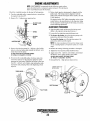
Engine Adjustments .............................................32
Drive Belt Adjustment .................................... 32
Fuel Injectors ................................................. 32
Testing Engine Compression .......................... 33
Testing Oil Pressure ........................................ 33
Valve Clearance Adjustment ......................... .34
Injection Timing ............................................ 34
Hurth Transmissions ..........................................36
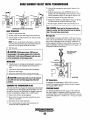
Changing Fluid ............................................... 37
Maintenance .................................................. 37
Cable Connections .......................................... 38
Shaft Couplings .............................................. 38
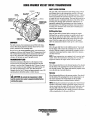
Borg Warner Transmission ................................ 39
Changing Fluid .............................................. .40
Maintenance .................................................. 41
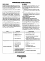
Transmission Troubleshooting ......................... .42
Lay-up and Recommissioning .......................... .44
Metric Conversions ......................................... .46
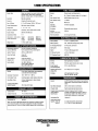
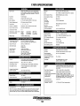
Specifications 80N4 ........................................ ..48
Specifications 11 OT4........................................ .49
Specifications 120N6 ........................................50
Specifications 170T6 ......................................... 51
Suggested Spares .............................................52
Parts Identification ................................................2
Introduction .............................................................3
Warranty Procedures ........................................ .3
Serial Number Location ................................. ..4
Admiral Control Panel ........................................ .5
Fuel, Engine Oil and Coolant ..............................6
Oil Pressure ...................................................... 6
Preparations for Initial Start-Up .........................7
Starting/Stopping Procedure ............................... 8
Warning Lights, Alarms and Circuit Breaker ...... 9
Engine Break-In Procedure ............................... 10
The Daily Routine ..............................................11
Starting the Engine ......................................... 11
Maintenance Schedule ..................................... 12
Cooling System ..................................................14
Thermostat ...................................................... 15
Raw Water Pump ............................................ 16
Heat Exchanger .............................................. 17
Air Intake Filter .............................................. 18
Fuel System .......................................................19
Fuel Lift Pump ................................................ 19
Fuel Filters ...................................................... 19
Fuel PumplFuel Bleeding ............................... 20
Engine Lubricating Oil ....................................... 21
Oil Change .................... :................................. 21
Remote Oil Filter ............................................ 22
Water Heater .....................................................23
DC Electrical System ...........................................24
Alternator Troubleshooting ............................ 24
Battery ............................................................ 25
Glow Plugs ..................................................... 26
Engines & Generators
1
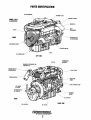
PARTS IDENTIFICATION
DC ALTERNATOR
ID NAME PLATE
EXHAUST ELBOW
MODEL 110T4
ILLUSTRATED
MANIFOLD
HEAT
-~----;;I--'--- EXCHANGER
COVER
FRONT
TRANSMISSION
FLUID DIPSTICK
RAW WATER
STARTER MOTOR
OIL DRAIN HOSE
LEFT SIDE
OIL FILL
THERMOSTAT
ASSEMBLY
MANIFOLD PRESSURE CAP
COOLANT FILL
CONNECTION
SIPHON BREAK
FUEL FILTER
TURBOCHARGER
INJECTION
PUMP
//.
FUEL PRIMING PUMP
AIR INTAKE/"
& FILTER
TRANSMISSION
OIL COOLER
BLE
MOUNT
OIL DIPSTICK
REAR
OIL GALLERY
RIGHT SIDE
OIL FILTER
Engines & Generators
2
INTRODUCTION
PRODUCT SOFTWARE
These high perfonnance marine engines are products of
WESTERBEKE's long years of experience and advanced
technology. We take great pride in the superior durability and
dependable perfonnance of our engines and generators.
Thank you for selecting WESTERBEKE.
Product software, (technical data, parts lists, manuals,
brochures and catalogs), provided from sources other than
WESTERBEKE are not within WESTERBEKE's control.
WESTERBEKE CANNOT BE RESPONSIBLE FOR THE
CONTENT OF SUCH SOFTWARE, MAKES NO WARRANTIES OR REPRESENTATIONS WITH RESPECT
THERETO, INCLUDING ACCURACY, TIMELINESS OR
COMPLETENESS THEREOF AND WILL IN NO EVENT
BE LIABLE FOR ANY TYPE OF DAMAGE OR INJURY
INCURRED IN CONNECTION WITH OR ARISING OUT
OF THE FURNISHING OR USE OF SUCH SOFTWARE.
WESTERBEKE customers should keep in mind the time
span between printings of WESTERBEKE product software
and the unavoidable existence of earlier WESTERBEKE
product software. The product software provided with
.
WESTERBEKE products, whether from WESTERBEKE or
other suppliers, must not and cannot be relied upon exclusively as the definitive authority on the respective product. It
not only makes good sense but is imperative that appropriate
representatives of WESTERBEKE or the supplier in question
be consulted to detennine the accuracy and currentness of the
product software being consulted by the customer.
In order to get the full use and benefit from your generator,
it is important that you operate and maintain it correctly.
This manual is designed to help you do this. Please read this
manual carefully and observe all the safety precautions
throughout. Should your engine require servicing, contact
your nearest WESTERBEKE dealer for assistance.
This is your operators manual. A parts catalog is also
provided and a technical manual is available from your
WESTERBEKE dealer. If you are planning to install this
equipment, contact your WESTERBEKE dealer for
WESTERBEKE'S installation manual.
WARRANTY PROCEDURES
Your WESTERBEKE Warranty is included in a separate
folder. If. after 60 days of submitting the Warranty Registry
fonn you have not received a customer identification card
registering your warranty, please contact the factory in
writing with model infonnation, including the unit's
serial number and commission date.
NOTES, CAUTIONS AND WARNINGS
Customer Identification Card
As this manual takes you through the operating procedures.
maintenance schedules, and troubleshooting of your marine
engine, critical infonnation will be highlighted by NOTES,
CAUTIONS, and WARNINGS. An explanation follows:
l"WV"JWESTERBEKE
I
NOTE: An operating procedure essential to note.
Customer Identification
MR. WESTERBEKE OWNER
MAIN STREET
HOMETOWN, USA
Model80N4
Ser. #UOOOO-E702
A CAUTION: Procedures which, if not strictly
observed, can result in the damage or destruction of
your engine.
Expires 2151200 I
A WARNING: Procedures which, if not properly
followed, can result in personal injury or loss of life.
The WESTERBEKE serial number is an alphanumeric
number that can assist in detennining the date of manufacture
of your WESTERBEKE engine or generator. The manufacturer's date code is placed at the end of the engine serial
number and consists of a character followed by three numbers. The character indicates the decade (A=1960s, B=1970s,
C=1980s, D=1990s E=2000s), the first number represents the
year in the decade: and the second and third numbers represent the month of manufacture.
Engines & Generators
3
INTRODUCTION
SERIAL NUMBER LOCATION
ORDERING PARTS
The engine's model number and serial number are located on
a nameplate mounted on the side of the engine's manifold.
The engine's serial number is stamped into the engine block
(left side) behind the alternator, below the manifold Take the
time to enter this information on the illustration of the nameplate shown below, as this will provide a quick reference when
seeking technical information and/or ordering repair parts.
Whenever replacement parts are needed, always provide the
engine model number and serial number as they appear on
the silver and black nameplate located on the manifold. You
must provide us with this information so we may properly
identify your engine. In addition, include a complete part
description and part number for each part needed (see the
separately furnished Parts List). Insist upon WESTERBEKE
packaged parts because will fit or generic parts are frequently
not made to the same specifications as original equipment.
~~~~~~~~~
~1¥fii4il:1B3=t
o
0
•
MODEL
SPEC
AVO_ MA USA
SPARES AND ACCESSORIES
Certain spares will be needed to support and maintain your
WESTERBEKE engine. Your local WESTE.RBEKE dealer
will a'ssist you in preparing an inventory of spare parts. See
the SPARE PARTS page in this manual. For engine accessories, see WESTERBEKE's ACCESSORIES brochure.
SER.NO..
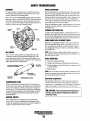
UNDERSTANDING THE DIESEL ENGINE
The diesel engine closely resembles the gasoline engine,
since the mechanism is essentially the same. The cylinders
are arranged above a closed crankcase. The crankshaft is the
same general type as a gasoline engine, and the diesel engine
has the same type of valves, camshaft, pistons, connecting
rods and lubricating system.
Therefore, to a great extent, a diesel engine requires the same
preventive maintenance as a gasoline engine. The most
important factors are proper ventilation and proper mamtenance of the fuel, lubricating and cooling systems. Fuel and
lubricating filter elements must be replaced at the time periods specified, and frequent checking for contaminants (water,
sediment, etc.) in the fuel system is also essential. Another
important factor is the consistent use of the same brand of
high detergent diesel lubrication oil designed specifically for
diesel engines.
The diesel engine' does differ from the gasoline engine,
however, in its method of handling and firing of fuel. The
carburetor and ignition systems are replaced by a single
component - the fuel injection pump - which performs the
function of both.
Engines & Generators
4
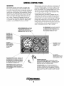
ADMIRAL CONTROL PANEL
DESCRIPTION
When the engine is shut down with the key switch turned off,
the water temperature gauge will continue to register the last
temperature reading indicated by the gauge before electrical
power was turned off The oil pressure gauge will fall to zero
when the key switch is turned off The temperature gauge
will once again register the engine's true temperature when
electrical power is restored to the gauge.
This manually-operated control panel is equipped with a
KEY switch and RPM gauge with an ELAPSED TIME
meter which measures the engine's running time in hours and
in III 0 hours. The panel also includes a WATER TEMPERATURE gauge which indicates water temperature in degrees
Fahrenheit, an OIL PRESSURE gauge which measures the
engine's oil pressure in pounds per square inch, and a DC
control circuit VOLTAGE gauge which measures the system's voltage. All gauges are illuminated when the key
switch is turned on and remain illuminated while the engine
is in operation. The panel also contains two rubber-booted
pushbuttons, one for PREHEAT and on,? for START.
A separate alarm buzzer with harness is supplied with every
Admiral Panel. The installer is responsible for electrically connecting the buzzer to the four-pin connection on the engine's
electrical harness. The installer is also responsib,le for installing
the buzzer in a location where it will be dry and where it will
be audible to the operator should it sound while the engine is
running. The buzzer will sound when the ignition key is turned
on and should silence when the engine has started and the
engine's oil pressure rises above 15 psi (1.1 kg/cm2).
OIL PRESSURE GAUGE: THIS GAUGE IS GRADUATED
IN POUNDS PER SQUARE INCH (PSI) AND IS
ILLUMINATED WHILE THE KEY SWITCH IS TURNED
ON. THE ENGINE'S NORMAL OPERATING OIL
PRESSURE RANGES BETWEEN 40 - 85 pSi.
WATER TEMPERATURE GAUGE: THIS GAUGE IS
GRADUATED IN DEGREES FAHRENHEIT AND IS
ILLUMINATED WHILE THE KEY SWITCH IS
TURNED ON. THE ENGINE'S NORMAL OPERATING
TEMPERATURE IS 170· -190· F(n· - SS·C).
RPM GAUGE: REGISTERS REVOLUTIONS
PER MINUTE OF THE
ENGINE AND CAN BE
RECALIBRATED FOR
ACCURACY FROM THE
REAR OF THE PANEL.
HOURMETER:
REGISTERS ELAPSED
TIME, AND SHOULD BE
USED AS A GUIDE FOR
THE MAINTENANCE
SCHEDULE.
SWITCH: PROVIDES
POWER ONLY TO THE
INSTRUMENT PANEL
CLUSTER.
,
PREHEAT
PRESSED, ENERGIZES THE
ALTERNATOR'S EXCITER, THE FUEL LIFT PUMP, THE
FUEL SOLENOID ON THE INJECTION PUMP, AND THE
ENGINE'S GLOW PLUGS. IT BYPASSES THE ENGINE'S
OIL PRESSURE ALARM SWITCH. IN ADDITION, THIS
BUTTON ENERGIZES THE START BUTTON.
DC VOLTMETER:
INDICATES THE AMOUNT THE
BATTERY IS BEING CHARGED.
SHOULb SHOW 13V TO 14V.
AUTOMATIC ALARM SYSTEM
I/<'
:
~...:
---
START BUTTON: WHEN PRESSED, ENERGIZES THE
STARTER'S SOLENOID WHICH CRANKS THE ENGINE.
THIS BUTTON WILL NOT OPERATE ELECTRICALLY
UNLESS THE PREHEAT BUTTON IS PRESSED AND HELD
AT THE SAME TIME.
SUPPLIED WITH THE INSTRUMENT PANEL. IF THE ENGINE'S COOLANT
REACHES 210· F (99·C), THIS SWITCH WILL CLOSE SOUNDING THE
ALARM WHICH WILL EMIT A CONTINUOUS SIGNAL.
OIL PRESSURE ALARM: AN OIL PRESSURE ALARM SWITCH IS
LOCATED OFF THE ENGINE'S OIL GALLERY. THIS SWITCH MONITORS
THE ENGINE'S OIL PRESSURE. SHOULD THE ENGINE'S OIL PRESSURE
FALL TO 5 -10 psi (0.4 - 0.7 kg/em'), THE SWITCH WILL CLOSE SOUNDING THE ALARM. IN THIS EVENT, THE ALARM WILL EMIT A PULSATING
SIGNAL.
Engines & Generators
5
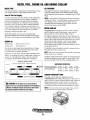
DIESEL FUEL, ENGINE OIL AND ENGINE COOLANT
DIESEL FUEL
OIL PRESSURE
Use fuel that meets the requirements or specification of Class
2-D (ASTM), and has a cetane rating of #45 or better.
The engine's oil pressure, during operation, is indicated
by the oil pressure gauge on the instrument panel. During
normal operation, the oil pressure will range between 25 and
85 psi.
Care Of The Fuel Supply
Use only clean diesel fuel! The clearance of the components
in your fuel injection pump is very critical; invisible dirt
particles which might pass through the filter can damage
these finely finished parts. It is important to buy clean fuel,
and keep it clean. The best fuel can be rendered unsatisfactory by careless handling or improper storage facilities. To
assure that the fuel going into the tank for your engine's daily
use is clean and pure, the following practice is advisable:
Purchase a well-known brand of fuel.
NOTE: A newly staned, cold engine can have an oil pressure
reading up to 85 psi. A warmed engine can have an oil pressure reading as low as 25 psi. These readings will vary
depending upon the temperature of the engine, the load
placed on the engine, and the RPM's.
ENGINE COOLANT
WESTERBEKE recommends a mixture of 50% antifreeze
and 50% distilled water. Distilled water is free from the
chemicals that can corrode internal engine surfaces.
Install and regularly service a good, visual-type fuel
filter/water separator between the fuel tank and the engine.
The Raycor 445 or larger is a good example of such a filter.
The antifreeze performs double duty. It allows the engine to
run at proper temperatures by transferring heat away from the
engine to the coolant, and lubricates and protects the cooling
circuit from rust and corrosion. Look for a good quality
antifreeze that contains Supplemental Cooling Additives
(SCAs) that keep the antifreeze chemically balanced, crucial
to long term protection.
The distilled water and antifreeze should be premixed before
being poured into the cooling circuit.
ENGINE OIL
80N41120N6
API Grade CF or CG-4
l1OT41170T6
API Grade CG-4
Use the heavy duty engine oils as specified above. Change
the engine oil after an initial 50 hour break-in period and
every 100 hours of operation thereafter.
Engine oil viscosity largely affects engine startability, performance, oil consumption, speed of wearing and occurrence of
seizure, etc. Using lubricants whose viscosity is selected
according to the atmospheric temperature is important.
NOTE: Look for the new environmentally-friendly long lasting
antifreeze that is now available.
Antifreeze mixtures will protect against an unexpected freeze
and they are beneficial to the engine's cooling system. They
retard rust and add to the life of the circulating pump seal.
ENGINE OIL VISCOSITY CHART
ENGINE OIL VISCOSITY GRADE - AMBIENT TEMPERATURE
I
I
I
SAE lOW
_SA.
SAE 2020W
.1
SAE 30
ANTIFREEZE PROTECTION
40.501
Antifreeze Concentration
Freezing Temperature
.I
23%
30%
14°F
8°F
(-10°C) (-13°C)
35%
50%
COOLANT RECOVERY TANK
A coolant recovery tank kit is supplied with each
WESTERBEKE diesel engine. The purpose of this recovery
tank is to allow for engine coolant expansion and contraction
during engine operation, without the loss of coolant and
without introducing air into the cooling system. This kit is
provided and must be installed before operating the engine.
A CAUTION: Do not allow two or more brands of
engine oil to mix. Each brand contains its own additives;
additives of different brands could react in the mixture
to produce properties harmful to your engine.
NOTE: This tank, with its short run of plastic hose, must be
located above the level of the engine's manifold.
\\
",
Engines & Generators
6
PREPARATIONS FOR INITIAL START-UP
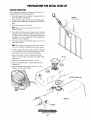
PRESTART INSPECTION
Before starting your engine for the first time or after a prolonged layoff, check the following items:
D Check the engine oil level. Add oil to maintain the level
DIPSTICK
PUSH IN TIGHT
at the high mark on the dipstick.
D Turn on the fuel supply, then check the fuel supply and
examine the fuel filter/water separator bowl for contaminants.
D Check the transmission fluid leveL
NOTE: Refer to the previous page for fuel, oil and
transmission fluid.
D Check the DC electrical system. Inspect wire connections
and battery cable connections. Make certain the positive
(+) battery cable is connected to the starter solenoid and
the negative (-) cable is connected to the engine ground
stud (this location is tagged).
D Check the coolant level in both the plastic recovery tank
and at the manifold.
NOTE: If the engine has not yet been filled with coolant,
refer to the COOLING SYSTEM section of this manual.
D Visually examine the engine. Look for loose or missing
parts, disconnected wires, and unattached hoses. Check
the threaded connections and engine attachments.
D Make certain there is proper ventilation around the
engine. An ample supply is necessary for proper engine
performance.
D Make sure the mounting installation is secure.
D Ensure the propeller shaft is securely attached to the
~
transmission.
D Open the through-hull and make certain raw water is
~
~ ""-..',
primed to the raw water strainer
~ ~
~
~/" ~
~,-~
"/',,---- .,,,1:'
..'"
;,\\1''--
,,\)1
",'\l'l/
'"
\~
'~I
.
'I
I
I
i /
j ?CcC"r~
COOLANT PRESSURE CAP
.'"
MANIFOLD
Engines & Generators
7
)
STARTING/STOPPING PROCEDURE
THE STARTING SYSTEM
5. Should the engine not start when the START button is
depressed for 10 to 20 seconds, release both buttons and
wait 30 seconds; repeat the procedure above and preheat
longer. Never run the starter for more than 30 seconds.
These marine diesel engine have l2V DC electric starters. The
start circuitry is designed so that the PREHEAT button must
be depressed for the time specified in the preheat chart. Then,
while keeping the PREHEAT button engaged, the START
button is depressed to crank the engine.
A CAUTION: Prolonged cranking Intervals wfthout
the engine starting can result in the engine exhaust
system filling wfth raw water. This may happen because
the pump Is pumping raw water through the raw water
cooling system during cranking. This raw water can
enter the engine's cylinders by way of the exhaust
manifold once the exhaust system fills. Prevent this
from happening by closing the raw water supply
through-hull shutoff, draining the exhaust muffler, and
correcting the cause of the excessive engine cranking.
Engine damage resulting from raw water entry is not a
warrantable issue; the owner/operator should keep this
in mind.
Starting Procedure
1. Place the transmission in neutral and advance the throttle
control to slightly open.
A
CAUTION: Make certain the transmission is
in neutral. Starting in gear could result in serious
damage to your transmission, your boat, and
vessels nearby.
2. Turn the KEY SWITCH to the ON position (2 o'clock).
3. Depress the PREHEAT switch. The voltmeter, panel
lights, gauges, meters and fuel solenoid will be activated.
The PREHEAT switch should be depressed in accordance
with the following chart:
6. Once the engine starts, check the instruments for proper
oil pressure and battery charging voltage.
TemperatureJPreheat
NOTE: Never attempt to engage the starter while the
Atmospheric Temperature
Preheating TIme
41°F(5°C) or higher
Approx. 5 seconds
41°F(5°C) to 23°F (-5°C)
Approx. 10 seconds
Starting Under Cold Conditions
23°F(-5°C) or lower
Approx. 15 seconds
Make sure the lubricating oil is appropriate for the prevailing
temperature. Use oil with an API Specification of CF or CG-4,
SAE 30. lOW-30, or 15W-40, or 20W-40.
The battery should be fully charged to minimize voltage drop.
Use a sufficient amount of preheat to aid in starting. See the
Temperature/Preheat chart elsewhere in this section.
engine is running.
NOTE: The START button will not energize unless the PREHEAT button is depressed. Depressing the PREHEAT button
activates the glow plugs in the cylinder head so use the PREHEAT intem!ittently to avoid overheating the glow plugs.
4. While still depressing the PREHEAT switch, depress the
START switch. This will engage the starter solenoid.
Upon engine starting, release the START switch and
release the PREHEAT switch.
12
NOTE: When starting:
A voltage drop will occur
when the preheat button
is depressed.
I
Stopping Procedure
To stop the engine, bring the throttle to an idle position and
place the transmission in neutral. Allow the engine to idle for
a few moments to stabilize temperatures. Turn the engine off
using the stop control cable.
NOTE: Make certain this key switch is in the OFF position
(12 o'clock). If the key switch is left ON, the battery will
discharge. An engine alarm buzzer is provided to warn the
operator of this condition (key switch ON). The best method
of preventing the battery from discharging is to remove the
key from the key switch after stopping the engine.
14
~6
\
~
L....J
",
'I,
\:i
ALTERNATOR WARNINGS
VOLTS
The Admiral Control Panel uses a voltmeter to monitor the
performance of the alternator.
COOLANT TEMPERATURE SWITCH
A coolant temperature switch is located on the thermostat
housing. This switch will activate a continuous alarm if the
coolant's operating temperature reaches approximately 210°F
(99°C).
Engines & Generators
8
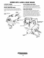
WARNING LIGHTS, ALARMS & CIRCUIT BREAKER
ALTERNATOR WARNINGS
LOW OIL PRESSURE ALARM SWITCH
The Admiral Control Panel uses a voltmeter to monitor the
performance of the alternator.
A low oil pressure alarm switch is located off the engine's
oil gallery. This switch's sensor monitors the engine's oil
pressure. Should the engine's oil pressure fall to 5 - IO psi
(0.4 - 0.7 kg/cm2), this switch will activate a pulsating alarm.
COOLANT TEMPERATURE SWITCH
A coolant temperature switch is located on the thermostat
housing. This switch will activate a continuous alarm if the
coolant's operating temperature reaches approximately 2IOOF
(99°C).
AIR BLEED
PETCOCK
COOLANT TEMPERATURE
SENDOR
ENGINE CIRCUIT BREAKER
The DC harness on the engine is protected by an enginemounted manual reset circuit breaker (20 amps DC).
Excessive current draw or electrical overload anywhere in the
instrument panel wiring or engine wiring will cause the
breaker to trip. In this event most engines will shut down
because the opened breaker disconnects the fuel supply. If
this should occur, check and repair the source of the problem.
After repairing the fault, reset the breaker and restart the
engine.
OIL PRESSURE SWITCH
(NORMALLY OPEN)
I
THERMOSTAT
HOUSING
OIL PRESSURE
SEND OR
FROM ENGINE
BLOCK
Engines & Generators
9
ENGINE BREAK-IN PROCEDURE
DESCRIPTION
Although your engine has experienced a minimum of one
hour of test operations at the factory to make sure accurate
assembly procedures were followed and that the engine operated properly, a break-in time is required. The service life of
your engine is dependent upon how the engine is operated
and serviced during its initial 50 hours of use.
Breaking-in a new engine basically involves seating the piston rings to the cylinder walls. Excessive oil consumption
and smoky operation indicate that the cylinder walls are
scored, which is caused by overloading the engine during the
break-in period.
Your new engine requires approximately 50 hours of initial
conditioning operation to break in each moving part in order
to maximize the performance and service life of the engine.
Perform this conditioning carefully, keeping in mind the following:
1. Start the engine according to the STARTING PROCEDURE section. Run the engine at fast idle while checking
that all systems (raw water pump, oil pressure, battery
charging) are functioning.
2. Allow the engine to warm up (preferably by running at
fast idle) until the water temperature gauge moves into
the 130 - 140°F (55 - 60°C) range.
3. While using the vessel, run the engine at various engine
speeds for the first 25 hours. Avoid prolonged periods of
idling.
4. Avoid rapid acceleration, especially with a cold engine.
5. Use caution not to overload the engine. The presence of a
grey or black exhaust and the inability of the engine to
reach its full rated speed are signs of an overload.
6. During the next 25 hours, the engine may be operated at
varying engine speeds, with short runs at full rated rpm.
Avoid prolonged idling during this break-in period.
CHECK LIST
o
o
o
o
Monitor the control panel gauges.
Check for leaks of fuel and engine oil.
Check for abnormal noise such as knocking, friction.
vibration and blow-back sounds.
Confirm exhaust smoke:
When the engine is cold - white smoke.
When the engine is warm - almost smokeless.
When the engine is overloaded - some black smoke and soot.
NOTE: See the TRANSMISSION section of this manualfor
break-in information on your transmission.
Engines & Generators
10
THE DAILY ROUTINE
CHECK LIST
STARTING THE ENGINE
Each day before starting your engine, take a few moments to
run this check list:
NOTE: See STARTING/STOPPING PROCEDURE in this
o
o
o
o
o
o
o
o
o
o
Visually inspect the engine for fuel, oil, or water leaks.
Check the oil level.
manual for more detailed instructions.
1. Put the transmission in neutral, throttle advanced.
NOTE: Hydraulically operated transmissions have a
neutral safety switch through which the starter solenoid
energizing circuit passes. This switch is open when the
transmission is in gear so the starter solenoid will not
energize.
Check the transmission fluid level.
Check for loose wires at the alternator.
Check the starting batteries (weekly).
Check drive belts for wear and proper tension (weekly).
Log your engine running time. These hours relate to
scheduled maintenance.
Check fuel supply; always keep fuel tank(s) as full as
possible.
2. Tum the KEY to the ON position (2 o'clock).
3. Depress PREHEAT (5 seconds).
4. While pressing PREHEAT, push START. As the engine
fires, release START and PREHEAT.
Look for clean fuel in the fueVwater separator bowl.
Check the coolant level in the plastic recovery tank.
NOTE: Some unstable running may occur in a cold
engine. This condition should abate as normal operating
temperature is reached and loads are applied.
NOTE: Excessive loss of coolant indicates a cooling system
leak. Check the entire system. If necessary, use a cooling system pres'sure tester to pressurize the cooling system to locate
the area of leakage. III cases of excessive coolant loss, refill
the svstem as outlined in the ENGINE COOLANT CIRCUIT
secti~n of this manual.
NOTE: Should the engine fail to start, wait 30 seconds,
then repeat the above procedure, and PREHEAT longer.
5. Allow a few minutes for the engine to warm at a comfortable rpm (approximately 1200 rpm), then reduce the
rpm, and get underway.
A CAUTION: When shifting the transmission, always
reduce the engine rpm to idle, then shift the transmission firmly from one direction to another. A slight pauSe
in neutral will allow the propeller to slow. Shifting at
high rpm will damage the transmission/damper plate.
Engines & Generators
11
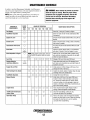
MAINTENANCE SCHEDULE
In order to use this Maintenance Schedule, it will be necessary to log your engine hours. Use your engine hounneter or
record your engine hours by running time.
NOTE: Many a/the/allowing maintenance procedures are
simple but others are more difficult and may require the
expert knowledge 0/ a service mechanic.
SCHEDULED
MAINTENANCE
CHECK
EACH
DAY
A WARNING: Never attempt to perform any service
while the engine is running. Wear the proper safety
equipment such as goggles and gloves, and use the
correct tools for each job. Disconnect the battery
terminals when servicing any of the engine's DC
electrical equipment.
HOURS OF OPERATION
50
100
250
500
MAINTENANCE DESCRIPTION
750 1000 1250
Fuel/Water Separator
0
0
Engine Oil Level
0
Oil level should indicate between MAX. and LOW on
dipstick.
Coolant Level
0
Check at recovery tank; if empty, check at manifold.
Add coolant if needed.
Transmission Fluid Level
0
Fluid level should indicate between MAX and LOW
on dipstick.
0
Inspect for proper tension (3/8" to 1/2" deflection)
and adjust if needed. Check belt edges for wear.
Fuel Supply
Drive Belts
Diesel No.2 rating of 45 cetane or higher.
Check for water and dirt in fuel (drain/replace filter
if necessary).
weekly
Visual Inspection of Engine
0
NOTE: Keep engine surface clean. Dirt and'
oil will inhibit the engine's ability to remain
cool.
0
Fuel Filter
Starting Batteries
(and House Batteries)
0
0
0
0
0
0
Check for fuel, oil and water leaks. Inspect wiring
and electrical connections. Keep bolts & nuts tight.
Check for loose belt tension.
Change at 50 hours then every 250 hours.
Check electrolyte levels every 50 operating hours
and make sure connections are very tight. Clean off
excessive corrosion.
weekly
Engine Oil and Filter
0
0
0
0
0
0
0
Initial engine oil &filter change at 50 hours, then
change both every 100 hours.
Heat Exchanger Zinc Anode
,
Fuel/Water Separator
0
0
0
0
0
0
0
Inspect zinc anode, replace if needed. Clear the heat
exchanger end of zinc anode debris.
0
0
0
0
Change filter every 200 hours.
0
0
0
0
Exhaust System
0
0
0
0
0
0
0
Engine Hoses
Throttle and Transmission
Control Cable
Raw Water Pump
0
Initial check at 50 hours, then every 250 hours.
Inspect for leaks. Check anti-siphon valve operation. Check the exhaust elbow for carbon and/or
corrosion buildup on inside passages; clean and
replace as necessary. Check that all connections are
tight. Check casting integrity.
0
Hose should be hard &tight. Replace if soft or
spongy. Check and tighten all hose clamps.
0
0
0
Check for loose fittings, cotter pins, etc.
Lubricate with WD-40 or equivalent.
0
0
0
Remove the pump cover and inspect the impeller,
gasket, cam and cover for wear. Check the bearings
and seals (the shaft can turn, but not wobble).
Lubricate when reassembling.
(continued)
--*
Engines & Generators
12
MAINTENANCE SCHEDULE
NOTE: Use the engine hourmeter gauge to log your engine hours or record your
engine hours by running time.
SCHEDULED
MAINTENANCE
CHECK
EACH
DAY
HOURS OF OPERATION
50
100
250
500
MAINTENANCE DESCRIPTION
750 1000 1250
0
Coolant System
0
DC Alternator
0
0
Drain, flush, and refill cooling system with
appropriate antifreeze mix.
0
Check DC charge from alternator. Check mounting
bracket; tighten electrical connections.
Transmission Oil Cooler
0
Remove; have professionally cleaned and pressure
tested.
Engine Transmission
Damper Plate
0
Chattering at idle and low rpms is an indication
of damper plate wear. Remove and replace.
0
*Fuellnjectors
Check and adjust injection opening pressure and
spray condition (Refer to your service manual).
*Starter Motor
0
0
Check solenoid and motor for corrosion. Remove
and lubricate. Clean and lubricate the starter motor
pinion drive.
*Preheat Circuit
0
0
Check operation of preheat solenoid. Remove and
clean glow plugs. Reinstall with anti-seize
compound on threads.
*Engine Cylinder
Compression
0
0
Check compression pressure and timing,
(see ENGINE ADJUSTMENTS).
* Adjust the Valve Clearances
0
0
*Heat Exchanger
0
Lubricate Panel Key Switch
with "Lockeze"
Transmission
Fluid and Filter
0
Feed Pump Strainer
Turbocharger
0
Adjust Valve Clearances, (see ENGINE
ADJUSTMENTS).
0
Remove, have professionally cleaned and pressure
tested.
0
0
0
0
0
At first 100 hours, then each year at winterizing.
0
0
0
0
0
Initial fluid change at 25 hours, then every
300 hours or at winterizing. Replace the filter at each
fluid change.
0
0
0
0
0
0
Clean every 250 operating hours.
0
*WESTERBEKE recommends this service be performed by an authorized mechanic.
Engines & Generators
13
Initial 50 hour check, inspect all connections for oil
and exhaust leaks. Check mounting bolts for
tightness. Check for air leakage. Inspect the radial
and axil play of the rotor shaft. Lubricate the shaft
bearings.
COOLING SYSTEM
DESCRIPTION
Westerbeke marine diesel engines are designed and equipped
for fresh water cooling. Heat produced in the engine by
combustion and friction is transferred to fresh water coolant
which circulates throughout the engine. This circulating fresh
water coolant cools the engine block, its internal moving
parts, and the engine oil. The heat is transferred externally
from the fresh water coolant to raw water by means of a heat
exchanger, similar in function to an automotive radiator. Raw
water flows through the tubes of the heat exchanger while
fresh water coolant flows around the tubes; engine heat
transferred to the fresh water coolant is conducted through
the tube walls to the raw water which is then pumped into the
exhaust system where finally it is discharged overboard. In
other words, the engine is cooled by fresh water coolant, this
coolant is cooled by raw water, and the raw water carries the
transferred heat overboard through the exhaust system. The
fresh water coolant and raw water circuits are independent of
each other. Using only fresh water coolant within the engine
.allows the cooling water passages to stay clean and free from
harmful deposits.
NOTE: Periodically check the condition of the manifold pressure cap. Ensure that the upper and lower rubber seals are ill
good condition and check that the vacuum valve opens and
closes tightly. Carry a spare cap.
CHANGING COOLANT
The engine's coolant must be changed according to the
MAINTENANCE SCHEDULE. If the coolant is allowed to
become contaminated, it can lead to overheating problems.
A CAUTION: Proper cooling system maintenance is
critical; a substantial number of engine fai/ures can be
traced back to cooling system corrosion.
FRESH WATER COOLING CIRCUIT
Drain the engine coolant by loosening the drain plug on the
engine block and opening the manifold pressure cap. Flush
the system with fresh water, then start the refill process.
NOTE: Refer to the ENGINE COOLANT section for the recommended antifreeze and water mixture to be used as the
fresh water coolant.
Fresh water coolant is pumped through the engine by a
circulating pump, absorbing heat from the engine. The
coolant then passes through the thermostat into the manifold,
to the heat exchanger where it is cooled, and returned to the
engine block via the suction side of the circulating pump.
When the engine is started cold, external coolant flow is
prevented by the closed thermostat (although some coolant
flow is bypassed around the thermostat to prevent,. the exhaust
manifold from overheating). As the engine warms up, the
thermostat gradually opens, allowing full flow of the engine's
coolant to flow unrestricted to the external portion of the
cooling system.
A WARNING: Beware of the hot engine coolant.
Wear protective gloves.
Coolant Recovery Tank
A coolant recovery tank allows for engine coolant expansion
and contraction during engine operation, without any
significant loss of coolant and without introducing air into
the cooling system. This tank should be located at or above
the engine manifold level and should be easily accessible.
~
TO COOLANT RECOVERY
TANK
)I-
DRAIN PLUG
DRAIN PETCOCK
COOLANT RETRACTION
...........
COOLANT EXPANSION
'\-...
,
I
Engines & Generators
14
SOME ENGINE MODELS ARE EQUIPPED
WITH A PETCOCK THAT ALLOWS FOR
A HOSE TO BE ATTACHED
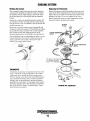
COOLING SYSTEM
Refilling the Coolant
Replacing the Thermostat
After closing the engine block drain, pour clean, premixed
coolant into the manifold and when the coolant is visible in
the manifold, start the engine and run it at slow idle. Open
the air bleed petcocks on the manifold and the thermostat
housing.
Monitor the coolant in the manifold and add as needed. Fill
the manifold to the filler neck and when the coolant flowing
from the petcock is free of air bubbles, close the petcock and
install the pressure cap.
Remove the cap on the coolant recovery tank and fill with
coolant mix to halfway between LOW and MAX and replace
the cap. Run the engine and observe the coolant expansion
flow into the recovery tank. When the petcock on the
thermostat housing is free of air bubbles, close that petcock.
After checking for leaks, stop the engine and allow it to cool.
Coolant should draw back into the cooling system as the
engine cools down. Add coolant to the recovery tank if
needed. Clean up any spilled coolant. . /
Remove the cap screws and disassemble the thermostat housing as shown. When installing the new thermostat and gasket,
apply a thin coat of sealant on both sides of the gasket before
pressing it into place. Do not over-tighten the cap screws.
Run the engine and check for normal temperatures and that
there are no leaks at the thermostat housing.
~'
"\
..---'
/
AIR BLEED
PETCOCK, y--..
~~~0:r~:1!~
~.,.
TEMPERATURE
Q
.~,
_<\11'
"'\j~\}~"
'.ij,j
THE GASKET IS GROOVED
FITS AROUND THE OUTER
EDGE OF THE THERMOSTAT
//
~~/THERMOSTAT
I'
A thennostat, located near the manifold at the front of the
engine, controls the coolant temperature as the coolant
continuously flows through the closed cooling circuit.
When the engine is first started, the closed thermostat prevents coolant from flowing (some coolant is by-passed
through a hole in the thermostat to prevent the exhaust
manifold from overheating). As the engine warms up, the
thermostat gradually opens. The thermostat is accessible
and can be checked, cleaned, or replaced easily. Carry a
spare thermostat and gasket.
CHANGING THE THERMOSTAT
Engines & Generators
15
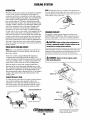
COOLING SYSTEM
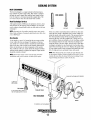
RAW WATER COOLING CIRCUIT
Changing the Raw Water Pump Impeller
The raw water flow is created by a positive displacement
impeller pump. This pump draws water directly from the raw
water source (ocean, lake, or river) through a hose to the
water strainer. The raw water passes from the strainer
through the raw water pump to the heat exchanger (through
the heat exchanger tubes) where it cools the engine circulating fresh water coolant. The raw water is then discharged
into the water-injected exhaust elbow, mixing with and cooling the exhaust gasses. This mixture of exhaust gas and raw
water is discharged overboard by the engine's exhaust gas
discharge pressure.
Close the raw water intake valve. Remove the pump cover
and, with the aid of an impeller puller, carefully pry the
impeller out of the pump. Install the new impeller and gasket.
Move the blades to conform to the curved cam plate and
push the impeller into the pump's housing. When assembling, apply a thin coating of lubricant to the impeller and
gasket. Open the raw water intake valve.
To be certain the pump is operating properly, run the engine
and check the following:
o Inspect the raw water pump for leaks.
o After warm up, monitor the temperature gauge. It should
indicate a normal engine temperature.
Check aft. There should be a steady flow of water from
the stem tube.
Raw Water Pump
o
The raw water pump is a self-priming, rotary pump with a
non-ferrous housing and a neoprene impeller. The impeller
has flexible vanes which wipe against a curved cam plate
within the impeller housing, producing the pumping action.
On no account should this pump be run dry as water acts as a
lubricant for the impeller. There should always be a spare
impeller and impeller cover gasket (an impeller kit) aboard.
Raw water pump impeller failures occur when lubricant (raw
water) is not present during engine operation. Such failures
are not warrantable, and operators are cautioned to make sure
raw water flow is present at start-up.
A CAUTION: If any of the vanes have broken off the
impeller, they must be found to prevent blockage in the
cooling circuit. They onen can be found in the heat
exchanger.
Impeller Puller
WESTERBEKE recommends using an impeller puller to
remove the impeller, this will prevent damage to the blades
and to the edges of the pump housing.
NOTE: Should a failure occur with the pump's internal parts
(seals and bearings). it may be more cost efficient to purchase a new pump and rebuild the original pump as a spare.
IMPELLER
INSPECTION: CHECK AT THE BASE OF
EACH BLAOE BY BENDING VIGOROUSLY.
REPLACE THE IMPELLER IF THERE
ARE ANY CRACKS.
WHEN INSTALLING: TAKE CARE TO ALIGN
THE IMPELLER KEYWAY WITH THE SHAFT
KEY. FOLD THE IMPELLER BLADES IN
EITHER DIRECTION (THEY WILL TURN IN
THE CORRECT POSITION WHEN THE
PUMP STARTS).
WATER LEAKING HERE WOULD
INDICATE THE PUMP SEAL HAS
FAILED AND THE PUMP NEEDS
IMMEDIATE SERVICE.
GREASE THE BLADES AND THE PUMP
CHAMBER WITH PETROLEUM JELLY
TO PROVIDE LUBRICATION FOR THE
FEW SECONDS THE PUMP HAS TO RUN DRY.
THE GREASE IMPROVES THE SEAL
OF THE BLADES AND MAKES INSTALLATION
EASIER.
~~~ft-*""---HOUSING
THE O-RING GASKET
ONLY NEEDS TO BE
.
REPLACED IF IT SHOWS ..
SIGNS OF WEAR.
Engines & Generators
16
RAW WATER PUMP
COOLING SYSTEM
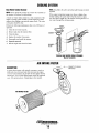
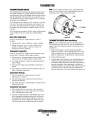
HEAT EXCHANGER
The heat exchanger is a copper cylinder which encloses a
large number of small copper tubes. Raw water is pumped
through the small copper tubes and the fresh water coolant
from the engine is circulated around the copper tubes. The
raw water removes heat from the fresh water coolant.
ZINC ANODES
Heat Exchanger Service
After approximately 1000 hours of operation, remove, clean
and pressure test the engine's heat exchanger. (A local automotive radiator shop should be able to clean and test the heat
exchanger.)
NEW
NOTE: Operating in silty and/or tropical waters may require
REPLACE
CLEAN & REUSE
If the zinc anodes need replacement, hold the hex boss into
which the zinc anode is threaded with a wrench while loosening the anode with another wrench. This prevents the hex
boss from possibly tearing off the exchanger shell. After
removing the zinc, note the condition of it. If the zinc is in
poor condition, there are probably a lot of zinc flakes within
the exchanger. Remove the end of the heat exchanger and
clean the inside of all zinc debris. Always have a spare heat
exchanger end gasket in case the present one becomes damaged when removing the end cover. Replace the gasket (refer
to your engine model's heat exchanger end gasket part number), O-ring and cover, and install a new zinc anode.
that a heat exchanger cleaning be perfonned more often than
every 1000 hours.
Zinc Anode
A zinc anode, or pencil, is located in the raw water cooling
circuit within the heat exchanger. The purpose of having
zinc anodes is to sacrifice them to electrolysis action taking
place in the raw water cooling circuit, thereby reducing the
effects of electrolysis on other components of the system.
The condition of the zinc anode should be checked monthly
and the anode cleaned or replaced as required. Spare anodes
should be carried on board.
NOTE: The threads of the zinc anodes are pipe threads and
do not require sealant. Sealant should not be used as it may
insulate the zinc from the metal of the heat exchanger hou;ing preventing electrolysis action on the zinc.
NOTE: Electrolysis action is the result of each particular
installation and vessel location; not that of the engine.
CLEAN OUT ACCUMULATED DEBRIS
CLEAN OUT
BOTH ENDS
ZINC ANODE
ALSO SERVES AS A DRAIN
FOR THE RAW WATER SYSTEM
HEAT EXCHANGER
GASKET
TO REMOVE HEAT EXCHANGER
17
COOLING SYSTEM
Raw Water Intake Strainer
NOTE: Also follow the above procedure after having run hard
aground.
NOTE: Always install the strainer at or below the waterline so
the strainer will always be self-priming.
A clean raw water intake strainer is a vital component of the
engine's cooling system. Include a visual inspection of this
strainer when making your periodic engine check. The water
in the glass should be clear.
Perform the following maintenance after every 100 hours of
operation:
1. Close the raw water seacock.
2. Remove and clean the strainer filter.
3. Clean the glass.
4. Replace the washer if necessary.
5. Reassemble and install the strainer.
6. Open the seacock.
7. Run the engine and check for leaks.
If the engine temperature gauge ever shows a higher than
normal reading, the cause may be that silt, leaves or grass
may have been caught up in the strainer, slowing the flow of
raw water through the cooling system.
WASHER
STRAINER
FILTER
TYPICAL RAW WATER INTAKE STRAINER
tOwner Installed]
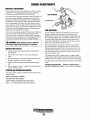
AIR INTAKE FILTER
........--CONNECTS TO ROCKER
ARM COVER
DESCRIPTION
A marine diesel engine will typically consume as much as
6,000 cubic feet of air per hour. Not only must the engine
room be well ventilated, the air flow into the engine must be
unrestricted. The air intake filter/cleaner should be inspected
every 100 operating hours. Clean/replace when needed.
AIR INTAKE FILTER
Engines & Generators
18
FUEL SYSTEM
DIESEL FUEL
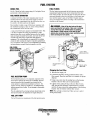
FUEL FILTERS
Use No.2 diesel fuel with a cetane rating of 45 or higher. Do not
use kerosene or home heating fuel.
The fuel injection pump and the fuel injectors are precisely
manufactured and they must receive clean diesel fuel, free
from water and dirt. To ensure this flow of clean fuel, the fuel
must pass through at least two fuel filters. a fuel/water separator and the engine's spin-on fuel filter. Visually inspect,
clean. and change these filters according to the maintenance
schedule in this manual.
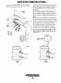
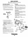
FUEL WATER SEPARATOR
A primary fuel filter of the water separating type must be
installed between the fuel tank and the engine to remove
water and other contaminants from the fuel before they can
be carried to the fuel system on the engine.
Most installers include a type of filter/water separator with
the installation package as they are aware of the problems
that contaminants in the fuel can cause.
A WARNING:
Shut off the fuel valve at the tank
when servicing the fuel system. Take care in catching
any fuel that may spill. DO NOT allow any smoking,
open flames or other sources of fire near the fuel
system when servicing. Ensure proper ventilation exists
when servicing the fuel system.
A typical fuel filter/water separator is iIIustrated below. This
is the Raycor Model 445. Keep in mind that if a water
separator type filter is not installed between the fuel supply
tank and engine-mounted fuel system, any water in the fuel
will affect the fuel pump, engine filter, and injection
equipment. The owner/operator is responsible for making
certain the fuel reaching the engine's injection equipment is
free of impurities. This process is accomplished by installing
and maintaining a proper filtration/separation system.
FUEL FILTER!
WATER SEPARATOR
[Owner Installed]
LIGHTLY WIPE
WITH CLEAN FUEL
TO LlFTPUMP
AND INCOMING
FUEL
TO INJECTION
PUMP
Changing the Fuel Filter
1. Shut the fuel supply off.
2. Loosen the fuel filter, turning counterclockwise with a
filter wrench. Place the used filter in a container for proper
disposal.
FUEL INJECTION PUMP
The fuel injection pump is a very important component of the
diesel engine. requiring the utmost care in handling. The fuel
injection pump has been thoroughly bench-tested and the
owner-operator is cautioned not to attempt to service it. If it
requires servicing, remove it and take it to an authorized fuel
injection pump service facility. Do not attempt to disassemble
and repair it.
3. Using a rag, wipe clean the sealing face on the housing
bracket so the new filter can be seated properly.
4. Lightly oil the sealing O-ring on the new filter. To reinstall, turn the filter assembly counterclockwise carefully
until the O-ring contacts the sealing surface of the housing
bracket. Turn 2/3 further with the filter wrench.
NOTE: The cartridge contains fuel. Take care not to spill it
during disassembly.
The only adjustment the servicing mechanic should make to the
fuel injection pump is the adjustment for engine idle speed.
FUEL LIFT PUMP
The fuel lift pump is an integral part of the fuel injection pump.
Engines & Generators
19
FUEL SYSTEM
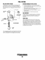
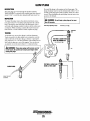
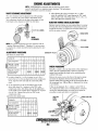
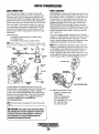
FUEL FEED PUMP STRAINER
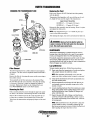
BLEEDING (PRIMING) THE FUEL SYSTEM
An additional fuel screen is located in the feed pump. This
screen (strainer) is removed for cleaning by releasing the
banjo bolt at the bottom. This screen should be cleaned every
250 operating hours. Use compressed air and/or clean with
kerosene.
1. Loosen the bleeding screw on the fuel injection pump.
TO FUEL FILTER
2. Tum the feed pump knob counterclockwise until the pump
knob is forced up by the spring.
3. Depressing the pump knob will cause it to drain out the air
mixed fuel from the loosened bleeding screws.
4. Repeat the pumping action until no bubbles are visible in
the flowing fuel.
5. Tighten the bleed screw and the feed pump knob.
FUEL ADDITIVES
INJECTION PUMP
BLEED SCREW
If fungus or bacteria is causing fuel problems, you should have
an authorized dealer correct these problems. Then use a diesel
fuel biocide to sterilize the fuel (follow the manufacturer's
instructions ).
SPARE PARTS
While the likelihood of having to service the system at sea is
slim, the possibility does exist. Therefore, we recommend that
banjo washers, injector seat washers and a fuel filter be carried on
board at all times. Purchase needed spare parts from your local
WESTERBEKE dealer or distributor. If a leak should develop at
a banjo washer that cannot be corrected by a simple tightening of
the fitting, replace the sealing washer with a replacement found in
the hardware kit for your model.
FEED PUMP
FUEL FEED PUMP
1.4---
BANJO
BOLT
After changing the fuel filter and cleaning the fuel feed pump
strainer, WESTERBEKE recommends the following procedure for ensuring there is no air trapped in the fuel system.
Engines & Generators
20
ENGINE LUBRICATING OIL
DESCRIPTION
The lubricating system is a pressure feeding system using an
oil pump. The engine oil is drawn from the oil sump by the
oil pump, which drives the oil, under pressure, through the
oil filter, oil cooler and various lubricating points in the .
engine. The oil then returns to the oil sump to repeat the
continuous cycle. When the oil pressure exceeds the
specified pressure, the oil pushes open the relief valve in the
oil pump and returns to the oil sump, keeping the oil pressure
within its specified range.
Oil Pressure
The engine's oil pressure, during operation, is indicated
by the oil pressure gauge on the instrument panel. During
normal operation, the oil pressure will range between 25 and
85 psi.
NOTE: Generic filters are not recommended. as the material standards or diameters of important items on generic
parts might be entirely different from genuine parts.
Immediately after an oil filter change and oil fill. run the
engine to make sure the oil pressure is normal and that
there are no oil leaks around the new oilfilter.
3. Filling the Oil Sump. Add new oil through the oil filler
cap on the top of the engine. After refilling, run the
engine for a few moments while checking the oil
pressure. Make sure there is no leakage around the new
oil filter or from the oil drain system, and stop the engine.
Then check the quantity of oil with the lube oil dipstick.
Fill to, but not over the high mark on the dipstick, should
the engine require additional oil.
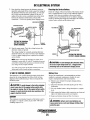
ENGINE OIL CHANGE
1. Draining the Oil Sump. Discharge the used oil through
the sump drain hose (attached to the front of the engine)
while the engine is wann. Drain the used oil completely,
replace the hose in its bracket, and replace the end cap
=urely.
.
1\ ~
SPIN ON
OIL FILTER
'~~~
FOR EXTENSION
1/4" NPT
SUMP
DRAIN
HOSE-_ _~
TURN HAND TIGHT AGAINST
O-RING. THEN TIGHTEN
2/3 OF A TURN.
O-RING
APPLY CLEAN
ENGINE OIL
WHEN INSTALLING
6"0.0.
Always observe the used oil as it is removed. A
yellow/gray emulsion indicates the presence of water in
the oil. Although this condition is rare, it does require
prompt attention to prevent serious damage. Call a
qualified mechanic should water be present in the oil.
Raw water present in the oil can be the result of a fault in
the exhaust system attached to the engine and/or a
siphoning of raw water through the raw water cooling
circuit into the exhaust, filling the engine. This problem is
often caused by the absence of an anti-siphon valve, its
poor location or lack of maintenance.
2. Draining the Oil Filter. Back off the drain plug until oil
flows from the drain (into an appropriate container). After
draining, remove the filter and wipe off any excess oil.
Tighten the drain plug.
When installing the new oil filter element, wipe the
filter's O-ring gasket's sealing surface free of oil and
apply a thin coat of clean engine oil to the rubber O-ring
on the new oil filter. Screw the filter onto the threaded oil
filter nipple on the oil filter bracket, and then tighten the
filter firmly by hand.
CUSTOMER OPTION
THIS WIRE CAN BE
USED TO ATTACH A
GAUGE OR ALARM
OEVICE TO MONITOR
THE CONDITION OF
THE OIL FILTER. THE
WIRE IS CURRENTLY
BUNDLED INTO THE
WIRING HARNESS.
CHANGING THE ENGINE OIL
Engines & Generators
21
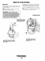
REMOTE OIL FILTER (OPTIONAL)
INSTALLATION
This popular accessory is used to relocate the engine's oil filter from the engine to a more convenient location such as an
engine room bulkhead.
NOTE: Refer to ENGINE OIL CHANGE in this manualfor
instructiollS on removing the oil filter.
To install, simply remove the engine oil filter and thread on
WESTERBEKE's remote oil filter kit as shown. Always
install this kit with the oil filter facing down as illustrated.
Contact your WESTERBEKE dealer for more information.
NOTE: Westerbeke is not responsible for engine failure due to
incorrect installation of the Remote Oil Filter.
A CAUTION: It Is Ifltal to Install the oill/nes
correctly. If the 011 flows In themvelSB dlmctlon, the
by-pass valve In the filter assembly will prevent the 011
from reaching the engine causing an Intemal engine
failure. If there Is no 011 pmssuTB reading, shutdown
immediately and check the hose connections.
FASTEN SECURelY TO A BULKHEAD
(SCREWS ARE OWNER SUPPLIED)
NOTE THE "IN" AND "OUT" MARKINGS
ON THE ADAPTER WHEN THE HOSES ARE
REMOVED FOR INSTALLATION SO THEY
WILL BE RECONNECTED CORRECTLY.
I
APPLY A THIN COAT OF CLEAN OIL TO THE FILTER GASKET WHEN INSTALLING. AFTER THE
FILTER CONTACTS THE BASE, TIGHTEN IT AN
ADDITIONAL 3/4 TURN.
APPLY A
COAT OF CLEAN OIL TO THE O-RING WHEN
INSTALLING THIS KIT. THREAD THE KIT ON, THEN HAND
TIGHTEN AN ADDITIONAL 3/4 TURN AFTER THE O-RING
CONTACTS THE BASE.
Engines & Generators
22
WATER HEATER CONNECTION (OPTIONAL)
As an accessory, WESTERBEKE wiJI provide a connector
that directs the engines hot water (coolant) flow to heat the
fresh water in the ships hot water tank.
ROCKER
COVER
The water heater shouKl be mounted in a convenient location
either in a high or low position in relation to the engine, so
that the connecting hoses from the heater to the engine can
run in a reasonably direct line without any loops which
might trap air.
Hoses should rise continuously from their low point at the
heater to the engine so that air will rise naturally from the
heater to the engine. If trapped air is able to rise to the heater,
then an air bleed petcock must be installed at the higher
fitting on the heater for bleeding air while filling the system.
NOTE: If any portion of the heating circuit rises above the
engine's closed cooling system pressure cap, then a pressurized (aluminum) remote expansion tank (Kit #024177) must
be installed in the circuit to become the highest point. Tee the
remote expansion tank into the heater circuit, choosing the
higher of the two connections for the return. Tee at the
heater; and plumb a single line up to the tank's location and
the other back to the engine's return. Install the remote
expansion tank in a convenient location so the fresh water
coolant level can easily be checked. The remote expansion
tank will now serve as a check and system fill point. The
plastic coolant recovery tank is not used when the remote
expansion tank kit is installed, since this tank serves the
same function.
ENGINE
FRONT
HOSES
CONNECT TO
THE HOT WATER
TANK (EITHER
CONNECTION)
CUT THE DISCARDED
MOLDED HOSE TO
PROVIDE THE TWO HOSE
CONNECTIONS THAT
ARE NEEDED TO ATTACH
THE CONNECTOR TO
THE ENGINE
REMOTE EXPANSION
TANK
WATER
HEATER
WATER
HEATER
Engines & Generators
23
DC ELECTRICAL SYSTEM
ALTERNATOR
1. Start the engine.
2. After the engine has run for a few minutes, measure the
starting battery voltage at the battery terminals using a
multimeter set on DC volts.
a. If the voltage is increasing toward 14 volts, the alternator is working; omit Steps 3 through 8 and go directly
to "Checking the Service Battery" on the next page.
h.If the voltage remains around 12 volts, a problem
exists with either the alternator or the charging circuit;
continue with Steps 3 through 8.
The charging system consists of a DC belt driven alternator
with a voltage regulator, an engine DC wiring harness, a
mounted DC circuit breaker and a battery with connecting
cables. Because of the use of integrated circuits (lC's), the
electronic voltage regulator is very compact and is mounted
internally or on the back of the alternator.
#14 GRAy==#=w__......
CIDJ
#14 PINK ~~~~~~~fiC-#14 BLUE=
(9)~~=#14 BROWN
o
MULTIMETER
COM
iB@lillili==== #10 REO
ENGINE
GROUND
,':1
SEE WIRING DIAGRAM
FOR WIRE CONNECTIONS
TO OPTIONAL ALTERNATORS.
ALTERNATOR TROUBLESHOOTING
TESTING THE STARTING
BATTERYIALTERNATOR
(ENGINE RUNNING)
A
WARNING: A failed alternator can become very
hot. 00 not touch until the alternator has cooled down.
-= GROUND
3. Turn off the engine. Inspect all wiring and connections.
Ensure that the battery terminals and the engine ground
connections are tight and clean.
Use this troubleshooting section to determine if a problem
exists with the charging circuit or with the alternator. If it is
determined that the alternator or voltage regulator is faulty,
have a qualified technician check it.
The alternator charging circuit charges the starting battery
and the service battery. An isolator with a diode, a solenoid
or a battery selector switch is usually mounted in the circuit
to isolate the batteries so the starting battery is not discharged
along with the service battery. If the alternator is charging the
starting battery but not the service battery, the problem is in
the service battery's charging circuit and not with the alternator.
A
CAUTION: To avoid damage to the battery
charging circuit, never shut off the engine battery
switch when the engine is running!
4. If a battery selector switch is in the charging circuit,
ensure that it is on the correct setting.
S. Turn on the ignition switch, but do not start the engine.
6. Check the battery voltage. If the battery is in good condition, the reading should be 12 to 13 volts.
Testing the Alternator
A
Cl2ID
CAUTION: Before starting the engine make certain
~W---MULTIMETER
that everyone is clear of moving parts! Keep away from
sheaves and belts during test procedures.
A
WARNING: When testing with a multimeter:
DC and AC circuits are often mixed together in marine
applications. Always disconnect a shore power cord,
iso/ate DC and AC converters, and shut down the engine
before performing DC testing. No AC .tests should be
made without a proper know/edge of AC circuits.
TESTING THE
ALTERNATOR VOLTAGE
(IGNITION ON - ENGINE OFF)
Engines & Generators
24
-= GROUND
DC ELECTRICAL SYSTEM
7. Now check the voltage between the alternator output terminal (B+) and ground. If the circuit is good, the voltage at
the alternator will be the same as the battery, or if an isolator is in the circuit the alternator voltage will be zero. If
neither of the above is true, a problem exists in the circuit
between the alternator and the battery. Check all the
connections - look for an opening in the charging circuit.
MULTIMETER
WITCH
Checking the Service Battery
Check the voltage of the service battery. This battery should
have a voltage between 13 and 14 volts when the engine is
running. If not, there is a problem in the service battery
charging circuit. Troubleshoot the service battery charging
circuit by checking the wiring and connections, the solenoid,
isolator, battery switch, and the battery itself.
CI2ID
0
COM
MumMETER
i
COM
~~a+"
TESTING THE STARTING
BATTERYIALTERNATOR
(ENGINE RUNNING)
I'
I
"\..
ENGIN E
GROUND
8. Start the engine again. Check the voltage between the
alternator output and ground.
The voltage reading for a properly operating alternator
should be between 13.5 and 14.5 volts. If your alternator
is over- or under-charging, have it repaired at a reliable
service facility.
SERVICE BATTERY
GROUND
NOTE: Before removing the alternator for repair; use a
voltmeter to ensure that 12 volts DC excitation is present
TESTING THE SERVICE
BATTERY (ENGINE RUNNING)
A
CAUTI,ON: To avoid damaging the alternator diodes,
do not use a high voltage tester (i.e. a megger) when
performing tests on the alternator charging circuit.
at the EXC terminal if the previous test showed only battery voltage at the B output terminal.
If 12 volts is not present at the EXC terminal, trace the
wiring and look for breaks and poor connections.
12 VOLT DC CONTROL CIRCUIT
Battery Care
The engine has a 12 volt DC electrical control circuit that is
shown on the wiring diagrams that follow. Refer to these
diagrams when troubleshooting or when servicing the DC
electrical system.
Review the manufacturer's recommendations and then
establish a systematic maintenance schedule for your
engine's starting batteries and house batteries.
o
A CAUTION: To avoid damage to the battery charging
o
circuit, never shut off the engine battery switch while
the engine is running. Shut off the engine battery SWitch,
however, to avoid electrical shorts when working on the
engine's electrical circuit.
o
o
Monitor your voltmeter for proper charging during
engine operation.
Check the electrolyte level and specific gravity with a
hydrometer.
Use only distilled water to bring electrolytes to a proper
level.
Make certain that battery cable connections are clean and
tight to the battery posts (and to your engine).
Keep your batteries clean and free of corrosion.
o
BAnERY
The minimum recommended capacity of the battery used in
the engine's 12 volt DC control circuit is 600 - 900 Cold
Cranking Amps (CCA).
A
WARNING: Sulfuric acid in lead batteries can
cause severe bums on skin and damage clothing. Wear
protective gear.
Engines & Generators
25
GLOW PLUGS
DESCRIPTION
The glow plugs are wired through the preheat solenoid.
When PREHEAT is pressed at the control panel this solenoid
should "click" on and the glow plug should begin to get hot.
Re-install the plugs in the engine and test them again. The
plugs should get very hot (at the terminal end) within 7 to 15
seconds. If the plugs don't heat up quickly, check for a short
circuit. When reinstalling the glow plugs, use anti-seize compound on the threads.
INSPECTION
To inspect the plug, remove the electrical terminal connections, then unscrew or unclamp each plug from the cylinder
head. Thoroughly clean each plug's tip and threads with a
soft brush and cleaning solution to remove all the carbon and
oil deposits. While cleaning, examine the tip for wear and
burn erosion; if it has eroded too much, replace the plug.
A WARNING: Do not keep a glow plug on for more
than 30 seconds.
Glow Plug Tightening Torque
19.5 H-Ib (2.7 m-kg)
~=:::::;IC;;;;==;;;:;):="""",!~
TESTING
An accurate way to test glow plugs is with an ohmmeter.
Touch one prod to the glow plug's wire connection, and the
other to the body of the glow plug, as shown. A good glow
plug will have a 0.4 - 0.6 ohm resistance. This method can be
used with the plug in or out of the engine. You can also use
an ammeter to test the power drain (5 - 6 amps per plug).
TERMINAL
END
TESTING A GLOW PLUG
WITH AN OHMMETER
KEYIPREHEAT-QPi
A WARNING: These glow plugs will become very hot
TIP
to the touch. Be careful not to burn your fingers when
testing the plugs.
~
GLOW PLUGS
TESTING A GLOW PLUG
USING A TEST LIGHT
/;
FROM PREHEAT
TERMINAL
+
Engines & Generators
26
WIRING SCHEMATIC
MARINE ENGINES #44781
+
~•. -______________~8~AT~T~E~RT~I~2~·2~.~V~O~C~________________
•
START
SOl.
IZV (
24V
C.B
C.B
20A
STARTER
lOA
OPTIONAL ALTERNATORS
e:
....
c
~
~
'"u....
.;
'"'
PRESlOLllE 12 AMP
ALl
TACHOMETER
KEY
SW.
$
VOLTMETER
ADMIRAL
PANEL
PRESlOLllE\LEECE-NEVILLE 90 AMP
ALl
PREHEAT
SWITCH
DISCONNECT JUMPER fOR
USE WITH TWO BATTERIES.
LESTEK 135
160.
190 AMP.
ALT.
~l"
Engines & Generators
27
!-ZUlli
WIRING DIAGRAM
MARINE ENGINES #44781
ALTERNATOR. 21Y 12A
I----~~~~~t-w_----_rt_------t_--J_--~
"'~" ,~
I
I
+~
~-===-
a
NEUTRAL
rTY
(USED
WI
H
DELSI
BATTERY
12-21 VDC
NOTES:
•
'NIS 'IOOUCI IS '.onenD IT " 1iI.. IiIUAL !tun ClIltUIl .RUln LOCATED IIUI TME
ITAnn. [attallV[ CUIIUT Will UUS[ Ttll .ltUl.lII TO nIP AIID THE [II&III( Will
SMUT DOI'IiI. 'HE IUILO[l/o.III[l MUST Sf SUII[ THU THE .IISTIUIiIUT p"ln, W.IIIIG. ,toIO
£IIG'I£ AlE ,.STALUD TO "II(VUT COII"CT en.EU [lECTlICAL OUlets AIID sUlun
2. 'II all-orr SWITCH I!tOULD IE IUTALUI IU.ElI THE I"HUr .. I' STAUn TO
DISCOI"I[(T THE ,aTTU' UI ,.. (MUGUel "liD ,,"£II LlAWl1IG TME 10AT ... SWnCM
WITH A COITIIIUGUS IU"IG or 115 Allrs AT 12 "DC WILL I[lV[ THIS rUIICTlOI. IMIS
$1. TeM 'MOULD lOT IE uUD TO MAil 01 .I[AI THE C !leUIT .
J. THE "11' 1.1It[ AT 'LUG Z IS .Iusn ".D SHOULD IE U'SULATED. CAPU'I
..
TME , • .,. II.I[ AT '"UG 1 IS
u.usn .... 0
"un
OIlU
SMOULD liE IIilSULun, ADlIIIAL ' u n Gell'
5 co. . lcr rill CIICUIl IIURU ".0 USIUOt .'I[ ro '"l "," rUII''''L rOt 12 WOlf
nSTUS OIU. FOt Z4 VOLT nSTtMs I[MOVI rill Clleulr IIUIII' "10 co.l[er rill
IUISTOI .,lIl ro rill .. 4 LT ILU WillS "ID rill. GlOUID rll[ .," rUM .."l
SI
PI
II
ADMIRAL
PANEL
-,
I
I
I
I
I
I
I
I,--_~~
I
I
I
I
IL
__
110 REO
Engines & Generators
28
ENGINE TROUBLESHOOTING
NOTE: The engine's electrical system is protected by a 20
ampere manual reset circuit breaker located on a bracket at
the back of the engine. The preheat solenoid is mounted on
the same bracket.
The following troubleshooting table describes certain problems
relating to engine service, the probable causes of these problems, and the recommendations to overcome these problems.
Problem
No panel indications; fuel solenoid
or fuel pump is not working (key switch
is on and PREHEAT button is depressed).
START button is depressed, no starter
engagement.
Engine cranks, but does not
start.
Probable Cause
VerificationJRemedy
1. Battery switch not on.
1. Check switch and/or battery connections.
2. 20-amp circuit breaker tripped.
2. Reset breaker; if breaker trips again. check preheat solenoid
circuit and check circuit for shorts to ground.
3. 10-amp breaker tripped on
preheat solenoid
3. Check the voltage both at and after the breaker on the
preheat solenoid - wait for it to cool then res~t.
4. Loose battery connections.
4. Check (+) connection to starter solenoid and (-) connection to
engine ground stud. Check battery cable connections.
5. Preheat solenoid not operating.
5. Check solenoid "S" terminal for voltage.
1. Connection to solenoid faulty.
1. Check connection.
2. Gear shift not in neutral.
2. Gear shift must be in neutral (see NEUTRAL SWITCH under
HURTH TRANSMISSIONS).
3. Faulty switch.
3. Check switch with ohmmeter.
4. Faulty solenoid.
4. Check that 12 volts are present at the solenoid connection.
5. Loose battery connections.
5. Check battery connections.
6. Low battery.
6. Check battery charge state.
1. Faulty fueling system.
1. Check that fuel valves are open.
1a. Check for air in fuel system. Bleed air from fuel system.
1b. Fuel filters clogged. Replace filters and bleed air from
fuel system.
2. Preheat solenoid faulty.
2. Check solenoid.
3. Low battery power.
3. Switch to combine house and start batteries.
3a. Replace batteries.
Engine can't be stopped.
1. Disconnect fuel shut-off cable.
off the fuel
1. Check connection at shut-off lever. Pull lever back to close
Battery runs down.
1. Oil pressure switch.
1. Observe if gauges and panel lights are activated when engine
is not running. Test the oil pressure switch.
2. High resistance leak to ground.
2. Check wiring. Insert sensitive (0 - .25 amp) meter in battery
lines. (Do not start engine.) Remove connections and replace
after short is located.
3. Low resistance leak.
3. Check all wires for temperature rise to locate the fault.
4. Poor battery connections.
4. Check cable connections at battery for loose connections,
corrosion
5. DC alternator not charging
5. Check connections, check belt tension, test alternator. See
(tachometer not operating).
DC ELECTRICAL SYSTEM/ALTERNATOR.
Battery not charging
1. Alternator drive.
1. Check drive belt tension; alternator should turn freely. Check
for loose connections. Check output with voltmeter. Ensure 12
volts are present at the Exc. terminal.
Engine slows and· stops.
1. Fuel starvation.
1. Check fuel supply, fuel valves, fuel lift pump.
2. 20 Amp circuit breaker tripping.
2. Check for high DC amperage draw during operation.
Ensure breaker is not overly sensitive to heat which would
cause tripping. Push button to reset.
3. Exhaust system is restricted.
3. Check for blockage, collapsed hose, carbon buildup at
exhaust elbow.
4. Water in fuel.
4. Pump water from fuel tank(s); change filters and
bleed fuel system.
5. Air intake obstruction.
5. Check air intake filter cartridge.
(continued)
Engines & Generators
29
ENGINE TROUBLESHOOTING
Problem
Probable Cause
Engine overheats.
Verification/Remedy
1. Raw water not circulating.
1. Raw water pump failure. Check impeller - replace.
2. Coolant not circulating.
2. Obstruction at raw water intake or raw water filter.
2a. Thermostat - remove and test in hot water.
Replace thermostat.
2b. Loss of coolant - check hoses, hose clamps, drain plug, etc.
lor leaks.
2c. Broken or loose belts - tighten/replace.
2d. Air leak in system; run engine and open the pressure cap to
bleed air. Add coolant as needed.
Engine alarm sound pulsates.
Engine alarm sounds continuously.
Exhaust smoke problems
1. Loss of oil.
1. Check dipstick, look for oil leaks at oil filter and at
oil drain hose connection.
2. Oil pressure switch.
2. Replace oil pressure switch.
1. Engine coolant.
1. Check engine coolant level.
2. High temperature switch opens at .
too Iowa temperature.
2. Check for satisfactory operation with switch bypassed,
check with ohmmeter, replace if faulty.
1. Blue smoke.
1. Incorrect grade of engine oil.
1a. Crankcase is overfilled with engine oil (oil is blowing out
through the exhaust).
2. White smoke.
2. Engine is running cold.
3. Black smoke.
3. Improper grade of fuel.
2a. Faulty injector or incorrect injector timing.
3a. Fuel burn incomplete due to high back-pressure in exhaust or
insufficient air for proper combustion (check for restrictions in
exhaust system; check air intake).
3b. Improperly timed injectors or valves, or poor compression.
3c. Lack of air - check air intake and air filter. Check for proper
ventilation.
3d. Overload.
TROUBLESHOOTING COOLANT TEMPERATURE AND OIL PRESSURE GAUGES
If both of the above gauge tests are positive, the gauge is
undoubtedly OK and the problem lies either with the
conductor from the sender to the gauge or with the sender.
If either of the above gauge tests are negative, the gauge is
probably defective and should be replaced.
Assuming the gauge is OK, check the conductor from the
sender to the sender tenninal at the gauge for continuity.
Check that the engine block is connected to the ground.
Some starters have isolated ground tenninals and if the
battery is connected to the starter (both plus and minus
tenninals), the ground side will not necessarily be connected
to the block.
If the gauge reading is other than what is nonnally indicated
by the gauge when the instrument panel is energized, the first
step is to check for 12 volts DC between the ignition (B+)
and the Negative (B-) tenninals of the gauge.
Assuming that there is 12 volts as required, leave the
instrument panel energized and perfonn the following steps:
1. Disconnect the sender wire at the gauge and see if the
gauge reads zero, which is the nonnal reading for this
situation.
2. Remove the wire attached to the sender tenninal at the
sender and connect it to ground. See if the gauge reads
full scale, which is the nonnal reading for this situation.
Engines & Generators
30
TACHOMETER
NOTE: Current model tachometers use a coarse adjustment
dial to set the tachometer to the crankshaft pulley rpms. The
calibrating screw is then used for fine tuning.
TACHOMETER/HOUR METER
The tachometerlhour meter used in propulsion engine instrument panels contains two separate electrical circuits with a
common ground. One circuit operates the hour meter and the
other the tachometer. The hour meter circuit operates on 12
volts alternator charging voltage supplied to the (+) terminal
on the back of the instrument.
The tachometer circuit operates on AC voltage 6-8 volts, fed
from one of the diodes in the alternator and supplied to the
tachometer input terminal while the engine is running, and
the alternator producing battery charging voltage 13.0-14.8
volts DC.
The following are procedures to follow when troubleshooting
a fault in either of the two circuits in a tachometerlhour
meter.
TERMINAL
COARSE
ADJUSTMENT
TACH INP
AC VOLTAGE
Hour meter Inoperative
Check for the proper DC voltage between (+) and (-)
terminals.
TACHOMETER CHECK (New Installation)
NOTE: In a new installation having new instrument panels.
the tachometer may not always be correctly calibrated to the
engine's rpm. This calibration should be checked in all new
installations.
1. Warm up the engine to normal operating temperature.
Remove any specks on the crankshaft pulley with a clean
cloth and place a piece of suitable reflecting tape on the
pulley to facilitate use of a photoelectric type tachometer.
1. Voltage present - meter is defective - repair or replace.
2. Voltage not present - trace (+) and (-) electrical connections for fault. (Jump 12 volts DC to meter (+)
terminal to verify the operation.)
Tachometer Inoperative
Check for the proper AC voltage between tachometer input
terminal and (-) terminal with the engine running.
2. Start and idle the engine.
1. Voltage present - attempt adjusting meter through calibration access hole. No results, repair or replace meter.
3. Aim the light of the tachometer onto the reflecting tape to
confirm the engine speed. Check the instrument panel
tachometer reading. Adjust the tachometer in the panel by
using the instrument coarse adjustment to calibrate the
instrument reading to the closest R.P.M. that the photo tach
is showing. Then use the fine calibration adjustment to
bring the instrument to the exact reading as the photo tach.
2. AC voltage not present - check for proper alternator DC
output voltage.
3. Check for AC voltage at tach terminal on alternator to
ground.
4. Check electrical connections from tachometer input terminal to alternator connection.
Tachometer Sticking
1. Check for proper AC voltage between "tach inp."
terminal and (-) terminal.
2. Check for good ground connection between meter (-)
terminal and alternator.
3. Check that alternator is well grounded to engine block at
alternator pivot bolt.
Tachometer Inaccurate
a. With a hand-held tach on the front of the crankshaft
pulley retaining nut or with a strobe-type tach, read the
front crankshaft pulley rpm at idle.
b. Adjust the tachometer with a small Phillips type screwdriver through the calibration access hole in the rear of
the tachometer. Zero the tach and bring it to the rpm
indicated by the strobe or hand tach. (Verify the rpm at
idle and at high speed and adjust the tach as needed).
Engines & Generators
31
ENGINE ADJUSTMENTS
DRIVE BELT ADJUSTMENT
Proper inspection, service and maintenance of the drive belts
is important for the efficient operation of your engine (see
Drive Belts under MAINTENANCE SCHEDULE).
Drive belts must be properly tensioned. Loose drive belts win
not provide proper alternator charging and will eventually
damage the alternator. Drive belts that are too tight will pun
the alternator out of alignment and/or cause the alternator to
wear out prematurely. Excessive drive belt tension can also
cause rapid wear of the belt and reduce the service life of the
coolant pump's bearing. A slack belt or the presence of oil on
the belt can cause belt slipping, resulting in high operating
temperatures and tachometer variations.
The drive belt is properly adjusted if the belt can be deflected
no less than 3/8 inch (lOmm) and no more than 112 inch
(12mm) as the belt is depressed with the thumb at the midpoint between the two pulleys on the longest span of the belt.
A spare belt or belts should always be carried on board.
A
WARNING: Never attempt to check Dr adjust the
drive belt's tension while the engine is in operation.
Adjusting Belt Tension
1. Loosen the alternator adjusting strap bolt and the base
mounting bolt.
2. With the belt loose, inspect for wear, cracks and frayed
edges.
3. Pivot the alternator on the base mounting bolt to the left
or right as required, to loosen or tighten.
4. Tighten the base mounting bolt and the adjusting strap
bolt.
5. Run the engine for about 5 minutes, then shut down and
recheck the belt tensions.
FUEL INJECTOR
HOLOOWN NUTS
FUEL INJECTORS
In case of severe vibrations and detonation noise, have the
injectors checked and overhauled by an authorized fuel
injection service center. Poor fuel quality, contaminants and
loss of positive fuel pressure to the injection pump can result
in injector faults. Since fuel injectors must be serviced in a
clean room environment, it is best to carry at least one extra
injector as a spare should a problem occur.
Before removing the old injector, clean the area around the
base of the injector to help prevent any rust or debris from
falling down into the injector hole. If the injector will not lift
out easily and is held in by carbon build-up or the like, work
the injector side-to-side with the aid of the socket wrench to
free it, and then lift it out.
The injector seats in the cylinder head on a copper sealing
washer. This washer should be removed with the injector and
replaced with a new washer when the new injector is installed.
The fuel injectors should be pressure tested after 750 operating
hours.
INJECTION STARTING PRESSURE
2630 psi (18.1 Mpa) (185 Kg/em')
INJECTION HOLDDOWN NUTS TORQUE 13.7 ± 1.5 It-Ib (1.9 ± 0.2 Kg-m)
STARTER AND ALTERNATOR SERVICE
The starter and the alternator should be serviced every 1200
operating hours.
Starter commentator cleaning.
Alternator slip ring cleaning.
Carbon brushes and the brush contact check.
Refer to your WESTERBEKE SERVICE MANUAL.
Engines & Generators
32
ENGINE ADJUSTMENTS
NOTE: WESTERBEKE recommends that the following engine adjustments be performed by a competent engine mechanic. The information
below is provided to assist the mechanic.
TESTING ENGINE COMPRESSION
OIL PRESSURE
Make certain the oil level (dipstick) is at the correct level
and the air intake filter is clean. The battery and starter motor
must also be in good condition.
1. Warm the engine to normal operating teITiperature.
The engine's oil pressure, during operation, is indicated
by the oil pressure gauge on the instrument panel. During
normal operation, the oil pressure will range between 40 and
85 psi.
2. Move the control lever to a position for shutting off the
fuel. (Disconnect the wires if a fuel shutdown solenoid
is used).
NOTE: A newly started, cold engine can have an oil pressure
reading up to 85 psi. A warmed engine can have an oil
pressure reading as low as 40 psi. These readings will vary
depending upon the temperature of the engine, the load
placed on the engine, and the RPM's.
3. Remove all the glow plugs from the engine and install
the compression gauge/adapter combination to the
cylinder on which the compression is to be measured.
Low Oil Pressure
The specified safe minimum oil pressure is 5 - 10 psi. A
gradual loss of oil pressure usually indicates worn bearings.
For additional information on low oil pressure readings, see
the ENGINE TROUBLESHOOTING chart.
MEASURING
COMPRESSION
Testing Oil Pressure
To test the oil pressure, remove the oil pressure sender, then
install a mechanical oil pressure gauge in it's place. After
warming up the engine, set the engine speed at idle and read
the oil pressure gauge.
DIAL GAUGE
OIL PRESSURE
15 - 20 psi at idle speed.
SENDER AND SWITCH TORQUE
9 - 13 n-Ib (1.2 - 1.8 m - Kg).
PREHEAT SOLENOID
4. Close the raw water seacock (thru-hull).
5. Crank the engine and allow the gauge to reach a
maximum reading, then record that reading.
6. Repeat this process for each cylinder.
20A BREAKER
COMPRESSION PRESSURE 441 psi (31.0 Kg/em') at 200 rpm.
ALLOWABLE LIMIT
370psi (26.0 Kg/em').
MAXIMUM PERMISSIBLE DIFFERENCE BETWEEN CYLINDERS
28.44 psi (2.0 Kg/em')
NOTE: Jfthe readings are below the limit, the engine needs an
overhaul.
7. Re-install the glow plugs and reset the fuel shut-off to the
run position.
S. Open the raw water seacock (thru-hull).
Low Compression
When low compression is found, determine the cause by
applying a small amount of oil in the cylinder thru the glow
plug hole. Allow the oil to settle.
Install the pressure gauge and repeat the above test. If the
compression reading rises dramatically, the fault is with the
rings. If the compression valve does not rise, the problem is
with the valves.
OIL PRESSURE
SWITCH
A slight rise in compression would indicate a problem with
both the rings and the valves.
Engines & Generators
33
ENGINE ADJUSTMENTS
NOTE: WESTERBEKE recommends that the following engine adjustments be performed by a competent engine mechanic. The information
below is provided to assist the mechanic.
VALVE CLEARANCE ADJUSTMENT
3. After adjusting the valves with piston No. I at IDC,
rotate the crankshaft 3600 again aligning the TDC mark
and the pulley mark. This brings piston No.6 or No.4 to
TDC, then adjust the remaining valves.
The valve clearance must be adjusted every 200 operating
hours. or whenever the valve rocker is abnormally noisy.
Valve adjustment should only be done when engine is cold.
Cold engine valve clearance is 0.0157 in (0.40 mm).
~..J ~D.D1571N
INJECTION TIMING CHECK/ADJUSTMENT
Improper injection timing can cause engine failure. In normal
servicing, this check and adjustment in unnecessary, however,
it might be necessary in conjunction with other related work
such as an engine overhaul.
'D.4DMMI
~VE
~ ~~EARANCE
TIMING MARKS
.........
'~::7'l'---TDC
MARK
NOTE: The
head bolts have been tightened with the
"Angular Tightening Method". Therefore, it is not necessary
to retighten the cylinder head bolts before adjusting the valve
clearances.
ADJUSTMENT PROCEDURE
PULLEY MARK
CRANKSHAFT PUllEY
Chart shows six cylinder model
Cylinder No.
Valve arrangement
When No.1 cylinder
is at TOC in the compression stroke
1
I
2
5
6
E I E I E I E I E
E I
O0 0
When No.6 cylinder is
at TOC in the compression stroke
4
3
0 0
0
@@
@@
CHECK PROCEDURE
Bring No. 1 piston to the top dead center on the compression
stroke. Turn the crankshaft pulley c1ockwi~e (viewed at
engine front) and align the mark on the crankshaft pulley
with the IDC mark.
Remove the access cover at the front of the injection pump
and check the alignment between the pointer A on the
injection pump gear lock plate and the projected pointer B on
the timing gear case. If A and B are in alignment, the timing
is set correctly.
If they are in alignment, No. 1 cylinder is at the TDC on
the compression stroke. If it is in misalignment, recheck by
turning the crankshaft pulley one more tum to repeat the
procedure to make sure that it is in alignment.
@@
1. In order to bring No. I or No.6 piston (six cyl.) No.4
piston (four cyl.) to the top dead center in the compression
stroke, align the TDC mark and the crank shaft pulley
mark.
2. Do the adjustment on the circle marked valves in the
above table where No. I piston is in the IDC in the
compression stroke. After these steps, do the adjustment
on the double circle marked valves where the No.6 piston
(six cyl.) No.4 piston (four cyl.)is on IDC in the
compression stroke.
Chart shows four cylinder model
Cylinder No.
Valve arrangement
IZ
=
a::
II.
When No.1 cylinder
is at TDC in the compression stroke
When No.4 cylinder is
at TOC in the compression stroke
2
1
I
E I
3
INJECTION
PUMP
MARKS
4
E I E I E
O0 0
0
@@
@@
Engines & Generators
34
ENGINE ADJUSTMENTS
NOTE: WESTERBEKE recommends that the following engine adjustments be peiformed by a competent engine mechanic. The information
below is provided to assist the mechanic.
Check the crankshaft position for the start of fuel injection.
1. Turn the crankshaft pulley counterclockwise viewed from
the engine front about 30°.
5. Notice which injection timing mark is aligned with the
pulley mark. The timing mark in alignment with the
pulley mark indicates the degrees before (IDC), the start
of fuel injection
The degrees before TDC differs depending on the engine
model. Refer to the specifications on the injection timing
for the respective model engine. If the timing is incorrect,
do the following adjustment.
2. Remove No. I high pressure injection line.
1'e1~DELIVERY
VALVE
HOLDER
ADJUSTMENT PROCEDURES
1. Align the pulley mark and the specified timing mark.
(Refer to the injection timing specifications.)
2. Loosen the four injection pump attachment nuts.
3. To advance the timing, pivot the injection pump at the
pump drive shaft away from the engine.
To retard the timing, pivot the injection pump at the
pump drive shaft toward the engine.
NOTE: The 1mm misalignment between the timing marks
on the crankshaft pulley correspond to about r in crank
angle.
4. Recheck the timing, following procedures I through 5.
5. Tighten the four injection pump attachment nuts.
6. Again remove No. I delivery valve holder, and reinstall
the delivery valve, spring and the valve holder.
::-~~~~*----- DELIVERY
VALVE
3. Remove the injection pump No. I delivery valve holder,
delivery valve and spring and reinstall the delivery valve
holder back into the pump.
DELIVERY VALVE HOLDER TIGHTENING TORQUE:
39 - 44 Nm (4 - 4.5 Kg-m!28.9 - 32.5 ft-Ib)
DELIVERY VALVE HOLDER TIGHTENING TORQUE:
39 - 44 Nm (4 - 4.5 Kg-m!28.9 - 32.5 ft-Ib)
4. Slowly turn the crankshaft pulley clockwise and at the
same time, feed fuel to the injuection pump by slowly
pumping the feed pump. When the fuel stops to flow out
from No. I delivery valve holder, stop tut;ning the crankshaft pulley and pumping. This is th~ beginning of fuel
injection.
.
7. Reinstall the No. I high pressure injection line.
LOOSEN FOUR NUTS
(80TH SIDES)
" PULLEY MARK
TIMING GEAR
CASE
Engines & Generators
35
HURTH TRANSMISSIONS
SHIPMENT
INITIAL OPERATION
For safety reasons, the transmission is not filled with transmission fluid during shipment and the selector lever is temporarily attached to the actuating shaft.
Set the shifting lever to neutral position (N). Start the engine
and let it run long enough in idle to fill the cooler and hoses
with transmission fluid. Shift into gear, forward and reverse;
shifting should be smooth and positive. Direct changes from
forward to reverse are permissible since the mUltiple disc·
clutch permits changing at high rpm including sudden reversing at high speeds in the event of danger.
After initial operation, make a visual inspection of the output
coupling, oil cooler and hoses, and the cable connections to
the transmission.
Before leaving the WESTERBEKE plant, each transmission
undergoes a test run, with Dextron III ATF transmission fluid.
The residual fluid remaining in the transmission after draining acts as a preservative and provides protection against corrosion for at least one year if properly stored.
DIPSTICK
~;;iJ#N~k--AIR VENT
LOCKING THE PROPELLER
Locking of the propeller shaft by an additional brake is not
required: use the gear shift lever position opposite your direction of travel for this purpose. Never put the gear shift in the
position corresponding to the direction of travel of the boat.
~~IJt,........~.JJ-- FLUID
FIlTER
\l:I....e3IN
WHEN UNDER SAIL OR BEING TOWED
Rotation of the propeller without a load, such as when the
boat is being sailed, being towed or anchored in a river, as
well as operation of the engine with the propeller stopped
(for charging the battery), will have no detrimental effects on
the transmission.
OUTPUT
COUPLING - -.....
MODEL 630
NOTE: When the boat is being sailed (engine stopped), the
gear shift must be in the neutral position. The propeller is at
idle and can free-wheel.
OIL COOLER
The oil cooler, mounted above the transmission, provides
continuous cooling for the transmission fluid. Raw water
passes through the tubes of the cooler and discharges overboard. The transmission fluid is cooled as it flows around the
tubes and back into the transmission.
WESTERBEKE RECOMMENDS CARRYING
ASPARE OIL COOLER ABOARD
DAILY OPERATION
o
o
o
o
RAW WATER
CONNECTION
Check the transmission fluid.
Visually check the gear shift linkage and transmission.
Start the engine in neutral, allowing a few minutes at idle
to warm the fluid.
Shift into gear.
NOTE: Too Iowan idle speed will produce a chattering noise
from the transmission gear and damper plate. In such cases
the idle speed should be increased.
RAW WATER
CONNECTION
TRANSMISSION OIL COOLER
Operating Temperature
The operating temperature of the transmission should not
exceed 176°F (80°C) under normal continous running. A
connection for a temperature probe is provided. At maximum
output of the engine, the fluid may reach 220°F (l04°C).
TRANSMISSION FLUID
Fill the transmission with Dextron l/l ATF. The fluid level
should be up to the mark on the dipstick. After checking the
level, press the dipstick into the case and turn it to tighten.
During the first 25 operating hours, inspect the bell housing,
output shaft and transmission cooler for leakage. The fluid
should be changed after the first 25 hours and every 300
hours thereafter.
A CAUTION: If the transmission fluid temperature is
too high, stop the engine immediately and check the
transmission fluid.
NEUTRAL SWITCH
These transmissions are equipped with a neutral safety
switch. This is to prevent the engine fr<,Jrn starting in gear.
Unless the transmission selector lever is perfectly aligned in
neutral, the engine starter will not activate.
Engines & Generators
36
HURTH TRANSMISSIONS
CHANGING THE TRANSMISSION FLUID
Replacing the Fluid
Pour in new Dextron 1Il ATF fluid and check the quantity
with the dipstick.
Transmission fluid quantities will vary with the use of coolers, length of hoses and the angle of the transmission.
Approximate Quantities
HURTH 45 -
2.12 quarts (2.0 Liters)
HURTH 63 - 3.2 quarts (3.0 Liters)
Reinsert the filter assembly into the housing. Press it in place
and tighten the Allen screw.
ACTUATING
LEVER
NOTE: Some transmissions use a "T" handle in place of a
screw on their filter assemblies.
16mm (8") SCREW
After running the engine, shut down and recheck the fluid level.
A WARNING: Neller pull out the dipstick while the
engine Is ronnlng. Hot nuld will splash from the dipstick
hole. This could cause sellere bums.
MAINTENANCE
O-RINGS
Transmission maintenance is minimal. Keep the exterior
housing clean, check the fluid level as part of your regular
routine, and change the fluid every 300 operating hours.
MODEL 450
Periodically inspect the transmission and the cooler for leaks
and corrosion. Make certain the air vent is clear and when
checking the fluid level look for signs of water contamination
(fluid will appear as strawberry cream).
FILTER ELEMENT
Lay-upJWinterize
Storage requires special care. Follow these procedures:
Filter Element
D Drain water from the transmission oil cooler and replace
The Hurth transmission has a filter element located opposite
the dipstick. This filter must be replaced whenever the fluid is
changed.
with a proper mixture of antifreeze coolant.
NOTE: This operation will normally occur when the
engine raw water cooling system is properly winterized.
Remove the filter by loosening the screw on the cover using a
6mm Allen wrench.
D Clean up the transmission and touch up unpainted areas
Twist and pull out the filter and remove the element. Place
the new filter onto the cover and lock it into place by turning
it clockwise. Check the O-rings for damage and replace if
necessary. Replacement filters can be obtained from your
local WESTERBEKE dealer or ZF (Hurth dealer).
(use heat resistant paint).
D
D
Removing the Fluid
Push a suction pump hose down through the pipe hole (under
the filter) to the bottom of the housing and suck out the fluid.
Remove the oil return line from the cooler and allow the oil
to drain into a container, then reconnect the oil return line.
Wipe down the transmission and properly dispose of the used
fluid.
D
Fill the transmission with Dextron 1Il ATF fluid to prevent internal corrosion (extended storage only, twelve
months or more).
Loosen attaching hardware from the transmission output
flange and propeller shaft coupling flange before removing the boat from the water. Separate the flanges and
spray with lubricant.
Inspect the gear shift cable, linkage, and attachments.
Look for corrosion of the end fittings, cracks or cuts in
the conduit, and bending of the actuator rods. Lubricate
all moving parts.
NOTE: If the transmission is to be stored for a 10llg time
(twelve months or more), it should be topped off with
fluid to prevent internal corrosion. Reduce the fluid level
before putting the engine back into service.
Engines & Generators
37
HURTH TRANSMISSIONS
CABLE CONNECTIONS
SHAn COUPLINGS
. The transmission is suitable for a single lever gear shift.
Upon loosening the retaining screw, the actuating lever (see
illustration) can be moved to any position required for the
control elements (cable or rod linkage). Make certain that the
actuating lever does not contact the lever hub: the minimum
distance between the lever and hub should be 0.02in(0.5mm).
The control cable or rod should be arranged at a right angle
to the actuating lever when in the neutral position. The neutral position of the gear shift lever on the control console
should coincide with the neutral position of the lever on the
transmission.
Shifting Positions:
A= Propeller rotation opposite of engine rotation.
N= Neutral position
B= Propeller rotation same as engine rotation.
NOTE: When shifting to "A" or "B" positions. make sure the
shift lever travel is sufficient for the actuating lever to contact
its stop. CABLE
N
WESTERBEKE recommends a flexible connection between
the transmission and the propeller shaft if the engine is flexibly mounted, in order to compensate for angular deflections.
The installation of a special propeller thrust bearing is not
required, since the propeller thrust will be absorbed by the
transmission bearing, provided the value specified under
SPECIFICATIONS is not exceeded. However, the output
shaft should be protected from additional loads. Special care
should be taken to prevent torsional vibration. When using a
universal joint shaft, make certain to observe the manufacturer's instructions.
Even with the engine solidly mounted,the use of a flexible
coupling or "DRIVESAVER" will reduce stress in the gearbox
bearings caused by hull distortions, especially in wooden
boats or where the distance between the transmission output
coupling and stern gland is less than about 800mm.
NOTE: When installing the transmission, make certain that
shifting is not impeded by restricted movability of the cable
or rod linkage, by unsuitably positioned guide sheaves, too
small a bending radius or other restrictions. In order to
mount a support for shift control cable connections, use the
two threaded holes located on the cable bracket mounted 011
the gear housing. Refer to the WESTERBEKE parts list.
BRACKET
GEAR SHIFT LEVER
8
ACTUATING
LEVER
LEVER HUB
ACTUATING
LEVER
1- 0.021n
r(0.5mm)
TYPICAL STEERING STATION
A greater amount of actuating lever travel is in no way
detrimental and is recommended. However, if the lever travel
is shorter, proper clutch engagement might be impeded
which, in turn, would mean premature wear, excessive heat
generation and clutch plate failure. This would be indicated
by slow clutch engagement or no engagement at all (see
CONTROL CABLES under TRANSMISSION
TROUBLESHOarING)
For additional information contact:
HURTH MARINE GEAR
ZF Industries
Marine US Headquarters
3131 SW 42nd Street
Fort Lauderdale, FL 33312
Tel.: (954) 581-4040
Fax: (954) 581-4077
NOTE: Check for proper actuating lever travel at least each
season.
A CAUTION: The position of the mechanism behind
the actuating lever Is factory-adjusted to ensure equal
shift lever travel from neutral position to A and B. If
this mechanism Is In any way tampered with. the
transmlsslDn wananty will be' vDld.
Engines & Generators
38
BORG WARNER VELVET DRIVE TRANSMISSION
SHIFT LEVER POSITION
OIL COOLER
The gear shift control mechanism and linkage must position
the actuating lever on the transmission exactly in Forward
(F), Neutral (N), and Reverse (R) shifting positions. A detent
ball located behind the transmission lever must work freely
to center the lever in each position. The gear shift positions at
the helm must be coordinated with those of the Velvet Drive
actuating lever through shift mechanism adjustments. An
improperly adjusted shift mechanism can cause damage to
the transmission. The shifting mechanism and transmission
actuating lever should be free of dirt and well lubricated to
ensure proper operation.
Shifting Into Gear
Place the gear shift in Neutral before starting the engine.
Shifting from one selector position to another selector position may be made at any time below 1000 rpm and in any
order. Shifts should be made at the lowest practical engine
speed. Start the engine and set the throttle at idle speed;
allow the transmission fluid to warm up for a few minutes.
SHIPMENT
Neutral
For safety reasons, the transmission is not filled with transmission fluid during shipment and the selector lever is temporarily attached to the actuating shaft.
Move the gear shift lever to the middle position. You should
feel the detent. This centers the actuating lever on the transmission. With the control in this position, hydraulic power is
completely interrupted and the output shaft of the transmission does not tum.
Before leaving the WESTERBEKE plant, each transmission
undergoes a test run, with Dextron III ATF transmission fluid.
The residual fluid remaining in the transmission after draining acts as a preservative and provides protection against
corrosion for at least one year if properly stored.
NOTE: Some transmissions are equipped with a neutral safety
switch. Unless the transmission actuating lever is perfectly
aligned in neutral, the engine starter will not activate.
TRANSMISSION FLUID
Check the transmission fluid level on the dipstick. If the
transmission has not been filled, fill with Dextron III and
continue to use this fluid. During the first 25 hours of operation, keep a lookout for any leakage at the bell housing, output shaft and transmission cooler. This fluid should be
changed after the first 25 hours and approximately every 300
operating hours thereafter and/or at winter lay-up.
Forward
Move the gear shift lever to the forward position. You should
feel the detent. The actuating lever on the transmission is in
the forward position. The output shaft and the propeller shaft
move the boat in a forward direction.
Reverse
Move the gear shift lever to the reverse position. You should
feel the detent. The actuating lever on the transmission is in
the reverse position. The output shaft and the propeller
should move the boat in a reverse direction (astern).
A CAUTION: Be ceffaln the transmission Is filled
and the correct slzs cooler Is properly Installed before
staffing the engine.
NOTE: Moving the transmission actuating lever from Neutral
Position to Forward is always toward the engine. Reverse is
always away from the engine. If boat moves backwards with
the gear shift control in the forward position, shut off the
engine! This problem may be a result of incorrect movement
of the actuating lever by the gear shift lever.
Engines & Generators
39
BORG WARNER VELVET DRIVE TRANSMISSION
o
o
FORWARD
NEUTRAL
Check the dipstick for the proper fluid level.
D
Replace the oil filler cap and dipstick. (Press the dipstick
into place and tum clockwise until finger-tight.)
D
Run the engine, shutdown and recheck the fluid level.
WARNING: Never pull out the dipstick while the
engine Is running. Hot nuld will splash from the dipstick
hole. This could cause severs bums.
DAILY OPERATION
Check the transmission fluid.
Visually check the gear shift linkage and transmission.
Oil Capacity
Start the engine in neutral. Allow a few minutes at idle
for the fluid to warm.
Approximately 2.5 quarts (2.36 liters) will fill most transmissions to the oil level fill mark on the dipstick. Many variables
have a direct relationship to the oil capacity. Additional oil
will be required to fill the oil cooler and the cooler lines. The
angle of installation will make a difference in the quantity of
oil required to fill the transmission.
.
NOTE: Too Iowan idle speed will produce a chattering
noise from the transmission gear and damper plate. In
such cases the idle speed should be increased.
o
D
A
REVERSE
TRANSMISSION AC11JATING LEVER POSITIONS
o
o
o
Clean off the transmission and properly dispose of the
used fluid.
Refill the transmission with DEXTRON /II ATF. The
quantity will vary depending on the transmission model
and the installation angle. Fill through the dipstick hole.
Shift into gear.
A
____ Make certain the rubber
seal Is screwed tight
to the handle.
CAUTION: Shifting gears above 1000 rpm can
cause damage to the engine damper plate. Pulling the
throttle back to Idle when shifting gears will save wear
on the transmission and the damper plate.
INSPECTION
o
o
o
o
Visually check for oil leaks at the hydraulic connections.
Check for wear on the hydraulic lines and replace if
worn.
Lubricate the detent ball and shift cable attachments.
Inspect the shift linkage.
Inspect the transmission bolts; retorque if necessary.
A CAUTION: Clutch fallurs will occur If the transmis-
OILDIPsnCK
sion shift lellSr does not fully engage the detent ball
plISltlons.
Oil Temperature
A maximum oil temperature of 1900 P (88°C) is recommended. Discontinue operation anytime sump oil temperature exceeds 230 0 P (1lO D C).
CHANGING THE TRANSMISSION FLUID
After the initial 50 hour change, the transmission fluid should
be changed at every 300 operating hours thereafter or at winter haul-out. However, the fluid must be changed whenever it
becomes contaminated, changes color, or smells rancid.
Remove the oil filler cap and dipstick.
Remove the oil cooler return line and allow the oil to
drain into a container.
PRESSURE GAUGE
An optional mechanical pressure gauge can be installed at
the control panel to constantly monitor the pressure of the
transmission fluid. A normal reading at 2000 rpm in forward
gear should indicate 95 - 120 Ib-in2 (6.7 - 8.4 kg-cm 2) and be
constant.
o
o
o
Reconnect the oil cooler return line.
D Use a suction pump to remove the transmission oil
through the filler cap/dipstick hole.
EngInes & Generators
40
BORG WARNER VELVET DRIVE TRANSMISSION
MAINTENANCE
WARRANTY NOTES
Transmission maintenance is minimal. Keep the exterior
housing clean, check the fluid level as part of your regular
routine, and change the fluid every 300 operating hours.
Service manuals are available from your BORG WARNER
dealer.
For assistance, contact:
Periodically inspect the transmission and the cooler for leaks
and corrosion. Make certain the air vent is clear and when
checking the fluid level look for signs of water contamination
(fluid will appear as strawberry cream).
BORG WARNER
200 Theodory Rice Blvd.
New Bedford, MA 02745
Tel.: (508) 979-4881
BORG WARNER is aware of the shock loads that can be
placed on its gears as the result of mechanical propeller operation or fully reversing of the propeller blades while shiftIng.
Therefore torque loads and directional changes should be
made at low engine speeds. If it is found that a failure was
caused by a shock load, any warranty claim wiJI be denied.
Lay-up/Winterize
Storage requires special care. Follow these procedures:
Drain the water from the transmission oil cooler and
replace it with a proper mixture of antifreeze coolant.
o
NOTE: This operation will usually occur when the engine
raw water cooling system is properly winterized.
o
Clean up the transmission and touch-up unpainted areas
(use heat resistant paint).
o
Fill the transmission with Dextron III ATF fluid to prevent internal corrosion.
o
Loosen attaching hardware from the transmission
output flange and propeller shaft coupling flange before
removing the boat from the water. Separate the flanges
and spray with lubricant.
o
A CAUTION: System-related noises or vibrations can
occur at low engine speeds which can cause gear rattle
resulting In damage to the engine and/or transmission.
BORG WARNER Is not responsible for total systemrelated torsional vibration of this type.
If any problems occur with the transmission, see
TRANSMISSION TROUBLESHOOTING in this manual.
Inspect the gear shift cable, linkage, and attachments.
Look for corrosion of the end fittings, cracks or cuts in
the conduit, and bending of the actuator rods. Lubricate
all moving parts.
NOTE: If the transmission is to be stored for a long time
(twelve months or more), it should be topped off with
fluid to prevent internal corrosion. Reduce the fluid level
before putting the engine back into service.
Engines & Generators
41
TRANSMISSION TROUBLESHOOTING
CONTROL CABLES
OIL COOLERS
The majority of transmission difficulties arise as a result of
improper clutch adjustments (manual transmissions) or problems with control cables (hydraulic transmissions) rather than
from problems with the transmission itself.
The continued flow of raw water through the cooler will, in
time, erode the inside of the cooler causing cross leaks to
occur. These internal cooler leaks will cause one of the following two problems:
HURTH clutches, in particular, are very sensitive to improper
cable adjustments.
1. Transmission fluid will leak into the flow of raw water
and be discharged overboard through the engine exhaust.
A loss of transmission fluid will cause the transmission to
fail.
If you experience operating problems with the transmission,
shut the engine down. First check the transmission-oil level,
then have a helper move the cockpit shift lever through the
full range - from neutral to full forward, back to neutral,
into full reverse, and back to neutral - while you observe
the actuating lever on the transmission. If the remote is stiff
to operate, break the cable loose at the transmission and try
again. If it is still stiff, check the cable for kinks or excessively tight bends, and check any linkage for binding. A new
cable and perhaps a new linkage mechanism may be needed.
While the cable is loose, shift the transmission in and out of
gear using the lever on the side of the transmission to make
sure there's no binding inside the case.
If the transmission passes these tests, crank the engine and
have a helper put it in forward and reverse while you observe
the propeller shaft; if the shaft isn't turning, the transmission
needs professional attention. If it does tum but there's no
thrust, check to see you still have a propeller on the end of
the shaft or, if you have a folding or feathering propeller, that
it isn't stuck in the "no pitch" position.
Problem
Transmission gears cannot be shifted.
Shifting pressure too low.
Transmission noise becomes louder.
2. The raw water will leak into the transmission fluid causing an increase in transmission fluid. This contaminated
fluid will appear as strawberry cream. The transmission
will eventually fail.
Either case requires an immediate response:
1. Install a new oil cooler.
2. Refill the transmission with DEXTRON III ATF.
If water has contaminated the fluid, the transmission fluid
needs to be cleaned out and replaced with fresh fluid. It will
take several fluid changes to get rid of the contamination.
Check your dipstick each time until it appears as pure transmission fluid. Change the transmission filter and clean out
the fluid lines that connect to the cooler.
If the transmission fails to shift properly, it will most likely
need the attention of a qualified transmission service facility.
A transmission cooler may last ten years or more but, in
some circumstances, depending on operating hours, tropical
waters, maintenance, etc. it might only last half that time.
WESTERBEKE recommends having a spare cooler aboard.
Probable Cause
VerlflcatlonJRemedy
1. Shifting lever is loose.
1. TIghten damping bolt on shifting lever.
2. Shifting cable is broken, bent or
unattached.
2. Check the cable, reattach or replace.
3. Loss of transmission fluid.
3. Check for leaks at transmission seal and output shaft.
Tighten gear case bolts. Check all oil hoses for leaks.
Oil cooler leak - see OIL COOLER.
4. Water in transmission fluid.
4. Replace oil cooler (see OIL COOLER). High water in engine
compartment, remedy cause. Shifting pressure too low, see
item 2.
1. Improper fluid.
1. Replace with DEXTRON 1/1 ATF.
2. Filter is dirty (if applicable).
2. Replace filter.
3. Water in transmission fluid.
3. Replace oil cooler - see OIL COOLER.
4. Transmission fluid too low.
5. Air vent is clogged.
4. Add fluid.
5. Remove painVdirt from vent.
1. Fluid level too low,
1. Top up with fluid to marking on dipstick.
so that pump sucks in air.
2. Damage starting on flexible coupling due
to wear or fatigue, possibly due to misalignment between engine. and transmission.
2. Replace flexible coupling. Check alignment between engine
and transmission.
3. Beginning damage of bearings in transmission due to torsional vibrations, running
without fluid, overload, wrong alignment of
transmiSSion, or excessive engine output.
3. Transmission needs professional attention.
(continued)
Engines & Generators
42
TRANSMISSION TROUBLESHOOTING
Problem
Probable Cause
VerlficatlonJRemedy
Chattering transmission noise,
mainly at low engine speed.
1. The engine or propeller generates torsional
1. Mount a flexible coupling with another stiffness factor
vibrations in the drive unit which produces
a "chattering" noise in the transmission.
between the engine and transmission; a coupling with
a higher stiffness factor might be sufficient.
Transmission shifts into gear, but
fails to propel the boat.
1. Output coupling Is not tuming.
1. Transmission needs professional attention.
2. Propeller shaft is not turning.
Output coupling is tuming.
2. The coupling bolts are sheared or the coupling is slipping
on the propeller shaft. Tighten or replace set screws, keys,
pins and coupling bolts as necessary.
3. Output coupling and
propeller shaft are turning.
3. Inspect the propeller; it may be missing or damaged.
A folding propeller may be jammed.
Variable pitch propeller may be in "no pitch" position.
NOTE: If you suspect a major problem in your transmission,
immediately contact your WESTERBEKE dealer or an
authorized marine transmission facility.
Engines & Generators
43
LAY-UP & RECOMMISSIONING
GENERAL
Fuel System [Gasoline]
Many owners rely on their boatyards to prepare their craft,
including engines and generators, for lay-up during the offseason or for long periods of inactivity. Others prefer to
accomplish lay-up preparation themselves.
Top off your fuel tanks with unleaded gasoline of 89 octane
of higher. A fuel conditioner ·such as STABIL gasoline
stabilizer should be added. Change the element in your
gasoline/water separator and clean the metal bowl.
Re-install and make certain there are no leaks. Clean
up any spilled fuel.
The procedures which follow will allow you to perform your
own lay-up and recommissioning, or you may use them as a
check list if others do the procedures.
Fuel System [Diesel]
These procedures should afford your engine protection
during a lay-up and also help familiarize you with the
maintenance needs of your engine.
Top off your fuel tanks with No.2 diesel fuel. Fuel additiyes
such as BlOB OR and STABIL should be added at this time to
control algae and condition the fuel. Care should be taken
that the additives used are compatible with the primary fuel
filter/water separator used in the system. Change the element
in your primary fuel filter/water separator, if the fuel system
has one, and clean the separator sediment bowl.
If you have any questions regarding lay-up procedures, call
your local servicing dealer; he will be more than willing to
provide assistance.
Propeller Shaft Coupling [Propulsion Engine]
Change the fuel filter elements on the engine and bleed the
fuel system, as needed. Start the engine and allow it to run
for 5 - 10 minutes to make sure no air is left in the fuel
system. Check for any leaks that may have been created in
the fuel system during this servicing, correcting them as
needed. Operating the engine for 5 - 10 minutes will help
allow movement of the treated fuel through the injection
equipment on the engine.
The transmission and propeller half couplings should always
be opened up and the bolts removed when the boat is hauled
out of the water or moved from land to water, and during
storage in the cradle. The flexibility of the boat often puts a
severe strain on the propeller shaft or coupling or both, while
the boat is taken out or put in the water. In some cases, the
shaft has actually been bent by these strains. This does not
apply to small boats that are hauled out of the water when
not in use, unless they have been dry for a considerable
period of time.
Raw Water Cooling Circuit
Close the through-hull seacock. Remove the raw water intake
hose from the seacock. Place the end of this hose into a five
gallon bucket of clean fresh water. Before starting the engine,
check the zinc anode found in the primary heat exchanger on
the engine and clean or replace it as required, and also clean
any zinc debris from inside the heat exchanger where the
zinc anode is located. Clean the raw water strainer.
Fresh Water Cooling Circuit
A 50-50 solution of antifreeze and distilled water is
recommended for use in the coolant system at all times.
This solution may require a higher concentration of
antifreeze, depending on the area's winter climate. Check the
solution to make sure the antifreeze protection is adequate.
Should more antifreeze be needed, drain an appropriate
amount from the engine block and add a more concentrated
mixture. Operate the engine to ensure a complete circulation
and mixture of the antifreeze concentration throughout the
cooling system. Now recheck the antifreeze solution's strength.
Start the engine and allow the raw water pump to draw the
fresh water through the system. When the bucket is empty,
stop the engine and refill the bucket with an antifreeze
solution slightly stronger than needed for winter freeze
protection in your area.
Start the engine and allow all of this mixture to be drawn
through the raw water system. Once the bucket is empty, stop
the engine. This antifreeze mixture should protect the raw
water circuit from freezing during the winter lay-up, as well
as providing corrosion protection.
Remove the impeller from your raw water pump (some
antifreeze mixture will accompany it, so catch it in a bucket).
Examine the impeller. Acquire a replacement, if needed, and
a cover gasket. Do not replace the impeller (into the pump)
until recommissioning, but replace the cover and gasket.
Lubrication System
With the engine warm, drain all the engine oil from the oil
sump. Remove and replace the oil filter and fill the sump
with new oil. Use the correct grade of oil. Refer to the
ENGINE LUBRICATING OIL pages in this manual for the
oil changing procedure. Run the engine and check for proper
oil pressure and make sure there are no leaks.
A CAUTION: Do not leave the engine's old engine
Cylinder Lubrication [Gasoline]
oil in the sump over the lay-up period. Engine oil and
combustion deposits combine to produce harmful
chemicals which can reduce the life of your engine's
internal parts.
With the engine running, remove the flame arrester and spray
fogging oil into the open air intake. The fogging oil will stall
out the engine as it coats the valves, cylinders and spark
plugs for winter protection.
Engines & Generators
44
LAY-UP &RECOMMISSIONING
Starter Motor
SPARE PARTS
Lubrication and cleaning of the starter drive pinion is advisable, if access to the starter permits its easy removal. Make
sure the battery connections are shut off before attempting to
remove the starter. Take care in properly replacing any electrical connections removed from the starter.
Lay-up time provides a good opportunity to inspect your
WESTERBEKE engine to see if external items such as drive
belts or coolant hoses need replacement. Check your basic
spares kit and order items not on hand, or replace those items
used during the lay-up, such as filters and zinc anodes. Refer
to the SPARE PARTS section of this manual.
Cylinder Lubrication [Diesel]
RECOMMISSIONING
If you anticipate a long lay-up period (12 months or more)
WESTERBEKE recommends removing the glow plugs or
fuel injectors for access to the cylinders. Squirt light
lubricating oil into the cylinders to prevent the piston rings
from sticking to the cylinder walls. Rotate the engine by hand
two revolutions then replace the glow plugs or injectors.
The recommissioning of your WESTERBEKE engine after a
seasonal lay-up generally follows the same procedures as
those described in the PREPARATIONS FOR STARTING
section regarding preparation for starting and normal starts.
However, some of the lay-up procedures will need to be
counteracted before starting the engine.
Make sure you have a replacement if removing the injector
sealing washer for the injector and fuel line return.
1. Remove any rags that were placed in the exhaust. intake
manifold, or flame arrester.
NOTE: If engine storage is going to be a lengthy one, 12
months or beyond, it is wise to rotate the engine by hand two
complete turns every additional 4 months to allow the injection pump components to move. This will help prevent their
sticking during extended storage periods.
2. Remove the raw water pump cover and gasket and discard
the old gasket. Install the raw water pump impeller
removed during lay-up (or a replacement, if required).
Install the raw water pump cover with a new cover gasket.
3. Reinstall the batteries that were removed during the layup, and reconnect the battery cables, making sure the
terminals are clean and that the connections are tight.
Check to make sure that the batteries are fully charged.
Intake Manifold and Thru-Hull Exhaust[Diesel]
Place a clean cloth, lightly soaked in lubricating oil. in the
opening of the intake manifold to block the opening. Do not
shove the cloth out of sight. (If it is not visible at
recommissioning, and an attempt is made to start the engine,
you may need the assistance of a servicing dealer.) Make a
note to remove the cloth prior to start-up. The through-hull
exhaust port can be blocked in the same manner.
4. Remove the spark plugs, wipe clean, re-gap, and install
to proper tightness. [Gasoline]
5. Check the condition of the zinc anode in the raw water
circuit and clean or replace the anode as needed. Note
that it is not necessary to flush the antifreeze/fresh water
solution from the raw water coolant system. When the
engine is put into operation, the system will self-flush in
a short period of time with no adverse affects. Also open
up the heat exchanger ends and clear out any accumulated debris.
Intake Manifold [Gasoline]
Clean the filter screen in the flame arrester, and place a clean
cloth lightly soaked in lube oil around the flame arrester to
block any opening. Also place an oil-soaked cloth in the
through-hull exhaust port. Make a note to remove cloths prior
to start-up!
6. Check the transmission fluid, if it had been topped off
during the lay-up, lower the level of the fluid to normal.
Transmission [Propulsion Engine]
[Propulsion Engine]
Check or change fluid in the transmission as required. If the
engine is to be layed up 12 months or more, fill the transmission to the very top to prevent corrosion. Lower the fluid to
its nonnaI at recommissioning. Wipe off grime and grease
and touch up unpainted areas. Protect coupling and output
flange with an anticorrosion coating, Refer to the
TRANSMISSION SECTION in this manual for additional
information.
7. Make certain all electrical connections and switches are
in the correct position and there are no-loads on the
generator at start up. [Generator]
8. Start the engine in accordance with the procedures
described in the PREPARATIONS FOR STARTING
section of this manual.
Batteries
If batteries are to be left on board during the lay-up period,
make sure they are fully charged, and will remain that way,
to prevent them from freezing. If there exists any doubt that
the batteries will not remain fully charged, or that they will
be subjected to severe environmental conditions, remove
the batteries and store them in a warmer, more compatible
environment.
Engines & Generators
45
METRIC CONVERSIONS
MILLIMETERS TO INCHES
INCHES TO MILLIMETERS
Inches
mm
1
2
3
4
5
10
25.40
50.80
76.20
101.60
127.00
254.00
mm
Inches
15
20
25
30
35
40
381.00
508.00
635.00
762.00
889.00
1016.00
mm
Inches
mm
Inches
1
2
3
4
5
10
0.0394
0.0787
0.1181
0.1575
0.1969
0.3937
15
20
25
30
35
40
0.5906
0.7874
0.9843
1.1811
1.3780
1.5748
10 MILLIMETERS = 1 CENTIMETER, 100 CENTIMETERS = 1 METER = 39.37 INCHES (3.3 FEET)
METERS TO INCHES
INCHES TO METERS
Inches
Meters
1
2
3
4
5
6
0.0254
0.0508
0.0762
0.1016
0.1270
0.1524
Meters
Inches
7
8
9
10
11
12
Meters
0.1778
0.2032
0.2286
0.2540
0.2794
0.3048
Inches
0.1
0.2
0.3
0.4
0.5
0.6
3.937
7.874
11.811
15.748
19.685
23.622
Meters
Inches
0.7
0.8
0.9
1.0
1.1
1.2
27.559
31.496
35.433
39.370
43.307
47.244
TO CONVERT METERS TO CENTIMETERS, MOVE DECIMAL POINT TWO PLACES TO THE RIGHT
METERS TO YARDS
YARDS TO METERS
Yards
Meters
Yards
Meters
Meters
Yards
Meters
1
2
3
4
5
0.91440
1.82880
2.74320
3.65760
4.57200
6
7
8
9
10
5.48640
6.40080
7.31520
8.22960
9.14400
1
2
3
4
5
1.09361
2.18723
3.28084
4.37445
5.46807
6
7
8
9
10
Yards
6.56168
7.65529
8.74891
9.84252
10.93614
MOVE DECIMAL POINT FOR HIGHER VALUES - e.g. 6,000 METERS = 6,561.68 YARDS
Ib
POUNDS TO KILOGRAMS
Ib
kg
kg
1
2
3
4
5
0.454
0.907
1.361
1.814
2.268
Gallons
Liters
6
7
8
9
10
kg
2.722
3.175
3.629
4.082
4.536
KILOGRAMS TO POUNDS
Ib
kg
1
2
3
4
5
2.205
4.409
6.614
8.818
11.023
GALLONS TO LITERS
1
2
3
4
5
3.79
7.57
11.36
15.14
18.93
6
7
8
9
10
LITERS TO GALLONS
Gallons
Liters
Liters
Gallons
10
20
30
40
50
37.86
75.71
113.57
151.42
189.28
1
2
5
10
20
0.26
0.53
1.32
2.64
5.28
Liters
60
90
120
150
180
Liters
Pints
Liters
Liters
Pints
Liters
1
2
3
4
5
0.47
0.95
1.42
1.89
2.37
6
7
8
9
10
2.84
3.31
3.79
4.26
4.73
1
2
3
4
5
2.11
4.23
6.34
8.45
10.57
6
7
8
9
10
TEMPERATURE
40
I
I
5
50
I
I
10
60
I
I
15
70
I
I
20
Gallons
15.66
23.77
31.32
39.62
47.54
LITERS TO PINTS
PINTS TO LITERS
Pints
32
I
I
0
Ib
13.228
15.432
17.637
19.842
22.046
75
I
I
25
85
I
I
30
95
I
I
35
105 140
I
I
I
I
40 60
Engines & Generators
46
175 212
I
I
I
I
80 100
Pints
12.68
14.79
16.91
19.02
21.13
OF
°C
STANDARD AND METRIC CONVERSION DATA
LENGTH-DISTANCE
Inches (in) x 25.4 = Millimeters (mm) x .0394 = Inches
Feet (ft) x .305 = Meters (m) x 3.281 = Feet
Miles x 1.609 = Kilometers (km) x .0621 = Miles
VOLUME
Cubic Inches (inJ) x 16.387 = Cubic Centimeters x .061 =in 3
Imperial Pints (IMP pt) x .568 = Liters (L) x 1.76 = IMP pt
Imperial Quarts (IMP qt) x 1.137 = Liters (L) x.88 = IMP qt
Imperial Gallons (IMP gal) x 4.546 = Liters (L) x .22 = IMP gal
Imperial Quarts (IMP qt) x 1.201 = US Quarts (US qt) x .833 = IMP qt
Imperial Gallons (IMP gal) x 1.201 = US Gallons (US gal) x .833 = IMP gal
Fluid Ounces x 29.573 = Milliliters x .034 = Ounces
US Pints (US pt) x .473 = Liters(L) x 2.113 = Pints
US Quarts (US qt) x .946 = Liters (L) x 1.057 = Quarts
US Gallons (US gal) x 3.785 = Liters (L) x .264 = Gallons
MASS-WEIGHT
Ounces (oz) x 28.35 = Grams (g) x .035 = Ounces
Pounds (Ib) x .454 = Kilograms (kg) x 2.205 = Pounds
PRESSURE
Pounds Per Sq In (psi) x 6.895 = Kilopascals (kPa) x .145 = psi
Inches of Mercury (Hg) x .4912 = psi x 2.036 = Hg
Inches of Mercury (Hg) x 3.377 = Kilopascals (kPa) x .2961 = Hg
Inches of Water (H20) x .07355 = Inches of Mercury x 13.783 = H20
Inches of Water (H20) x .03613 = psi x 27.684 = H20
Inches of Water (H20) x .248 = Kilopascals (kPa) x 4.026 = H20
TORQUE
Pounds-Force Inches (in-Ib) x .113 = Newton Meters (Nm) x 8.85 =in-Ib
Pounds-Force Feet (ft-Ib) x 1.356 = Newton Meters (Nm) x .738 = ft-Ib
VELOCITY
Miles Per Hour (MPH) x 1.609 = Kilometers Per Hour (KPH) x .621 = MPH
POWER
Horsepower (Hp) x .745 = Kilowatts (Kw) x 1.34 = MPH
FUEL CONSUMPTION
Miles Per Hour IMP (MPG) x .354 = Kilometers Per Liter (Km/L)
Kilometers Per Liter (Km/L) x 2.352 = IMP MPG
Miles Per Gallons US (MPG) x .425 = Kilometers Per Liter (Km/L)
Kilometers Per Liter (Km/L) x 2.352 = US MPG
TEMPERATURE
Degree Fahrenheit (OF) = (OC X 1.8) + 32
Degree Celsius (OC) = (OF - 32) x .56
Engines & Generators
47
80N4 SPECIFICATIONS
GENERAL
Engine Type
FUEL SYSTEM
Diesel, four cylinder, four-cycle, marine engine.
Vertical in-line overhead valve, water cooled
direct injection, 80 hp @ 2500 rpm.
General
Closed system with bleed points.
Fuel
No.2 diesel oil (cetane rating of 45 or higher).
Naturally aspirated.
Fuel Injection Pump
BOSCH Model A type (In-line).
Govemor
Integral with injection pump.
Fuel Injection Timing
WBTDC
Bore & Stroke
4.02 x 4.65 inches (102.0 x 118.0 mm).
Nozzle
Multi-hole
262 cubic inches (4.3 liter).
Fuel Filter
(on engine)
Full flow replaceable.
Air cleaner
Replaceable paper element.
Aspiration
Piston Displacement
Firing Order
1-3-4-2.
Direction of Rotation
Clockwise, when viewed from the front.
210 ft-Ib @ 1500 rpm.
AirFlow
(engine combustion)
150 efm.
Engine Torque
Compression Ratio
17:1
Fuel Consumption
4.7 U.S. gph (17.8 Iph).
Dimensions - inches (mm) Height
w/out transmission
Width:
Length:
Weight (dry)
32.0 inches
25.2 inches
47.2 inches
(813 mm)
(645mm)
(1168 mm)
ELECTRICAL SYSTEM
971 Ibs (440.8 kgs).
TUNE-UP SPECIFICATIONS
Starting Battery
12 Volt, (-) negative ground.
Battery Capacity
750 - 900 Cold Cranking Amps (CCA).
DC Charging A1temator
51 Amp rated, belt-driven.
Glow plugs.
Compression Pressure
(Limit of difference
441 psi (31 kg/cm') at 200 rpm
Not to exceed 28.44 psi (20.0 kg/cm').
Starting Aid
Starter
12 Volt, 3 KW.
Injector Pressure
2133 psi (150 kf/cm').
DC No-load Current
± 2% of rated amps.
Valve Seat Angle
Intake 45° ..
Exhaust 45°.
DC Cranking Current
400 CCA.
Valve Clearance
(engine cold)
Intake and exhaust.
0.Q16 inches (0.40 mm).
Engine Speed
Idle: 600 - 900 rpm.
Cruise: 1800 - 2200 rpm.
Max: 2400 -2500 rpm.
LUBRICATION SYSTEM
COOLING SYSTEM
Fresh water-cooled block. thermostaticallycontrolled with heat exchanger.
General
Operating Temperature
170 -190° F (77 - 88° C).
Fresh Water Pump
Centrifugal type, metal impeller, belt-driven.
Raw Water Pump
Positive displacement, rubber impeller,
engine-driven.
Coolant (Fresh Water)
System Capacity
EXHAUST SYSTEM
45° elbow
Exhaust Hose Size
4" I.D. (101.6 mm) hose
Oil Filter
Full flow, paper element, spin-on type.
Sump Capacity
(not including filter)
14.5 U.S. QIs (13.8 liters).
Operating Oil Pressu re
(engine hot)
25-85 psi.
Oil Grade
API Specification CF or CG-4,
SAE 30, 10W-30, 15W-40.
General
(HURTH Standard Transmission) Case-hardened
helical gears, hydraulically operated multiple disc
clutch.
Gear Ratio (Standard)
2:00:1 (Hurth 45A) or (Hurth 63A)
Propeller Shaft
Right handed-standard transmission.
Propeller Recommendations 22x16 P-2 blade or 22x14 P-3 blade
(using standard
propeller should allow the engine to reach its full
transmission)
rated rpm (2500 + 000 -100) at full open throttle
while underway in forward gear.
ENGINE AIR REQUIREMENTS
Combustion Air
Gear type/pressure circulation.
TRANSMISSION
17 US Qts (16.1 liters).
Exhaust Elbow
General
150 cfm
Note: The pressure differential between the outside of the engine compartment versus the inside of the engine compartment should not exceed 2
inches of water (51 mm) at full open throttle (measure with a manometer).
Lubricating Fluid
Dextron III
Transmission Sump
Capacity Hurth 45
2.13 US qts (2.0 liters) approximate.
Engines & Generators
48
110T4 SPECIFICATIONS
GENERAL
Engine Type
FUEL SYSTEM
Diesel, four cylinder, four-cycle, turbocharged
marine engine. Vertical in-line overhead valve,
water cooled direct injection, 110 hp @ 2400
rpm.
General
Closed system with bleed pOints.
Fuel
No.2 diesel oil (cetane rating of 45 or higher).
Fuel Injection Pump
BOSCH Model A type (In-line).
Aspiration
Turbo charged.
Fuel Injection liming
12° BTDC.
Govemor
Integral with injection pump.
Nozzle
Multi-hole.
Bore & Stroke
4.02 x 4.65 inches (102.0 x 118.0 mm).
Full flow replaceable.
Piston Displacement
202 cubic inches (4.3 liter).
Fuel Filter
(on engine)
Firing Order
1 - 3 - 4 - 2.
Air cleaner
Replaceable paper element.
Direction of Rotation
Clockwise, when viewed from the front.
Air Flow
(engine combustion)
230 cfm.
Engine Torque (max.)
280 ft-Ib @ 1500 rpm.
Fuel Consumption
6.1 U.S. gph (23.1 Iph).
Compression Ratio
17:1.
Dimensions - inches (mm) Height:
w/out transmission
Width:
Length:
Weight (dry)
32.0 inches
28.3 inches
47.2 inches
ELECTRICAL SYSTEM
(813 mm)
(719 mm)
(1168 mm)
987 Ibs (448.0 kgs).
TUNE-UP SPECIFICATIONS
Compression Pressure
(Limit of difference
441 psi (31 kg/cm') at 200 rpm
Not to exceed 28.44 psi (20.0 kg/cm').
Injector Pressure
2133 psi (150 kf/cm').
Valve Seat Angle
Intake 45°
Exhaust 45°
Valve Clearance
(engine cold)
Intake and exhaust
0.016 inches (0.40 mm).
Engine Speed
Idle: 600 - 900 rpm.
Cruise: 1800 - 2200 rpm.
Max: 2300 -2400 rpm.
General
Fresh water-cooled block, thermostaticallycontrolled with heat exchanger.
Operating Temperature
180 -190° F(77 - 88° C)
Fresh Water Pump
Centrifugal type, metal impeller, belt-driven.
Raw Water Pump
Positive displacement, rubber impeller,
engine-driven.
Battery Capacity
750 - 900 Cold Cranking Amps (CCA)
DC Charging Altemator
51 Amp rated, belt-driven
Starting Aid
Glow plugs
Starter
12 Volt, 3 KW
DC No-load Current
± 2% of rated amps
DC Cranking Current
400 CCA.
General
Gear type/pressure circulation
Oil Filter
Full flow, paper element, spin-on type.
Sump Capacity
(not including filter)
14.5 U.S. Qts (13.8 liters)
Operating Oil Pressure
(engine hot)
25-85 psi
Oil Grade
API Specification CF or CG-4,
SAE 30, 10W-30, 15W-40
TRANSMISSION
General
(HURTH Standard Transmission) Case-hardened
helical gears, hydraulically operated multiple disc
clutch.
Gear Ratio (Standard)
2:00:1 (Hurth 45A) or (Hurth 63A)
Propeller Shaft
Right handed-standard transmission.
17 US Qts (16.1 liters)
EXHAUST SYSTEM
Exhaust Elbow'
45° elbow
Exhaust Hose Size
4" 1.0. (101.6 mm) hose
Combustion Air
12 Volt, (-) negative ground
LUBRICATION SYSTEM
COOLING SYSTEM
Coolant (Fresh Water)
System Capacity
Starting Battery
Propeller Recommendations 24x18 P-2 blade or 24x16 P-3 blade
(using standard
propeller should allow the engine to reach its full
transmission)
rated rpm (2400 + 000 -100) at full open throttle
while underway in forward gear.
Lubricating Fluid
Dextron III
Transmission Sump
Capacity Hurth 45A
2.13 US Qts (2.0 liters) approximate.
230 cfm
Note: The pressure differential between the outside of the engine compartment versus the inside of the engine compartment should not exceed 2
inches of water (51 mm) at full open throttle (measure with a manometer).
Engines & Generators
49
120N6 SPECIFICATIONS
GENERAL
Engine Type
FUEL SYSTEM
Diesel, six cylinder, four-cycle, Vertical in-line,
overhead valve, fresh water cooled direct
injection, marine engine. 120 hp @2500 rpm.
General
Closed system with bleed pOints.
Fuel
No.2 diesel oil (cetane rating of 45 or higher).
Aspiration
Naturally aspirated.
Fuel Injection Pump
BOSCH Model A type (In-line).
Governor
Integral with injection pump.
Fuel Injection TIming
WBTDC
Bore & Stroke
4.13 x 4.92 inches (105.0 x 125.0 mm)
Nozzle
Multi-hole
Piston Displacement
296 cubic inches (6.5 liter)
Fuel Filter
(on engine)
Full flow replaceable.
Firing Order
1-5-3-6-2-4
Air cleaner
Replaceable paper element.
Direction of Rotation
Clockwise, when viewed from the front.
298 ft-Ib @1500 rpm.
Air Flow
(engine combustion)
240 cfm
Engine Torque
Compression Ratio
17:1
Fuel Consumption
6.5 U.S. gph (24.6Iph).
Dimensions - inches (mm) Height:
w/out transmission
Width:
Length:
Weight(dry)
32.5 inches
25.2 inches
56.4 inches
(823mm)
(645mm)
(1410 mm)
ELECTRICAL SYSTEM
1175 Ibs (534.1 kgs).
TUNE-UP SPECIFICATIONS
Starting Battery
12 Volt, (-) negative ground
Battery Capacity
750 - 900 Cold Cranking Amps (CCA)
DC Charging Alternator
51 Amp rated, belt-driven
Compression Pressure
(Limit of difference
441 psi (31 kg/cm') at 200 rpm
Not to exceed 28.44 psi (20.0 kg/cm').
Starting Aid
Glow plugs
Starter
12 Volt, 3 I<N{ actuated shift.
Injector Pressure
2631 psi (180 kf/cm').
DC No-load Current
±2% of rated amps
Valve Seat Angle
Intake 45°
Exhaust 45°
DC Cranking Current
400 CCA
Valve Clearance
(engine cold)
Intake and exhaust
0.016 inches (0.40 mm)
Engine Speed
Idle: 600 - 900 rpm
Cruise: 1800 - 2200 rpm
Max: 2400 -2500 rpm
LUBRICATION SYSTEM
COOLING SYSTEM
General
Fresh water-cooled block, thermostaticallycontrolled with heat exchanger.
Operating Temperature
180 - 1900 F (77 - 880 C)
Fresh Water Pump
Centrifugal type, metal impeller, belt-driven.
Raw Water Pump
Positive displacement, rubber impeller,
engine-driven.
Coolant (Fresh Water)
System Capacity
EXHAUST SYSTEM
45° elbow
Exhaust Hose Size
4" I.D. (101.6 mm) hose
Oil Filter
Full flow, paper element. spin-on type.
Sump Capacity
(not including filter)
22 U.S. qts (20.8 liters)
Operating Oil Pressure
(engine hot)
25 - 85 psi (3.5 - 4.2 kg/cm')
Oil Grade
API Specification CF or CG-4,
SAE 30, 1OW-3~, 15W-40
General
(HURTH Standard Transmission) Case-hardened
helical gears, hydraulically operated multiple disc
clutch.
Gear Ratio (Standard)
2:00:1 (Hurth 45A) or (Hurth 63A)
Propeller Shaft
Right handed-standard transmission.
Propeller Recommendations 22x16 P-2 blade or 22x14 P-3 blade
(using standard
propeller should allow the engine to reach its
transmission)
full rated rpm (2500 + 000 -100) at full open
throttle while underway in forward gear.
ENGINE AIR REQUIREMENTS
Combustion Air
Gear type/pressure circulation
TRANSMISSION
25 US qts (23.7 liters)
Exhaust Elbow
General
240cfm
Note: The pressure differential between the outside of the engine compartment versus the inside of the engine compartment should not exceed 2
inches of water (51 mm) at full open throttle (measure with a manometer).
Lubricating Fluid
Dextran /11
Transmission Sump
Capacity Hurth 45
Hurth 63
2.13 US qts (2.0 liters) approximate.
4.2 US qts (4.0 liters) approximate.
Engines & Generators
50
170T6 SPECIFICATIONS
GENERAL
Engine Type
FUEL SYSTEM
Diesel, six cylinder, four-cycle, turbocharged
marine engine. Vertical in-line overhead valve,
fresh water cooled direct injection, 170 hp @
2500 rpm.
General
Closed system with bleed points.
Fuel
No.2 diesel oil (cetane rating of 45 or higher).
Fuel Injection Pump
BOSCH Model A type (In-line).
Aspiration
Turbocharged.
Fuel Injection TIming
12° BTDC
Govemor
Integral with injection pump.
Nozzle
Multi-hole
Bore & Stroke
4.13 x 4.92 inches (105.0 x 125.0 mm)
423 cubic inches (6.5 liter)
Fuel Filter
(on engine)
Full flow replaceable.
Piston Displacement
Firing Order
1-5-3-6-2-4
Air cleaner
Replaceable paper element.
Direction of Rotation
Clockwise, when viewed from the front.
Air Flow
(engine combustion)
365 cfm.
Engine Torque (max.)
423 ft-Ib @ 1800 rpm.
Fuel Consumption
9.3 U.S. gph (35.2 Iph).
Compression Ratio
17:1
Dimensions - inches (mm) Height:
Width:
Length:
w/out transmission
Weight (dry)
33.5 inches
28.0 inches
57..5 inches
ELECTRICAL SYSTEM
(823 mm)
(711 mm)
(1410mm)
12451bs (565.23 kgs).
TUNE-UP SPECIFICATIONS
Compression Pressure
(Limit of difference
441 psi (31 kg/cm') at 200 rpm
Not to exceed 28.44 psi (20.0 kg/cm')
Injector Pressure
2631 psi (185 kf/cm').
Valve Seat Angle
Intake 45°
Exhaust 45°
Valve Clearance
(engine cold)
Intake and exhaust
0.016 inches (0.40 mm)
Engine Speed
Idle: 600 - 900 rpm
Cruise: 1800 - 2200 rpm
Max: 2400 -2500 rpm
12 Volt, (-) negative ground
750 - 900 Cold Cranking Amps (CCA)
DC Charging Alternator
51 Amp rated, belt-driven
Starting Aid
Glow plugs
Starter
12 Volt, 3 I<m
DC No-load Current
± 2% of rated amps
DC Cranking Current
400 CCA
LUBRICATION SYSTEM
COOLING SYSTEM
General
Starting Battery
Battery Capacity
Fresh water-cooled block, thermostaticallycontrolled with heat exchanger.
General
Gear type/pressure circulation
Oil Filter
Full flow, paper element, spin-on type.
Sump Capacity
(not including filter)
22 U.S. qts (20.8 liters)
Operating Oil Pressure
(engine hot)
25-85 psi
Oil Grade
API Specification CF or CG-4,
SAE 30, 10W-30, 15W-40
Operating Temperature
180 -190° F (77 - 88° C)
Fresh Water Pump
Centrifugal type, metal impeller, belt-driven.
Raw Water Pump
Positive displacement, rubber impeller,
engine-driven.
General
ened
(HURTH Standard Transmission) Case-hardhelical gears, hydraulically operated multiple
disc clutch.
25 US qts (23.7 liters)
Gear Ratio (Standard)
2:00:1 (Hurth 45A) or (Hurth 63A)
Propeller Shaft
Right handed-standard transmission.
Coolant (Fresh Water)
System Capacity
TRANSMISSION
EXHAUST SYSTEM
Exhaust Elbow
45° elbow
Exhaust Hose Size
4" 1.0. (101.6 mm) hose
Combustion Air
Propeller Recommendations 24x18 P-2 blade or 24x16 P-3 blade
(using standard
propeller should allow the engine to reach its
transmission)
full rated rpm (2500 + 000 -100) at full open
throttle while underway in forward gear.
Lubricating Fluid
Dextran III
Transmission Sump
Capacity Hurth 63
4.2 US qts (4.0 liters) approximate.
365 cfm
Note: The pressure differential between the outside of the engine compartment versus the inside of the engine compartment should not exceed 2
inches of water (51 mm) at full open throttle (measure with a manometer).
Engines & Generators
51
SUGGESTED SPARE PARTS
WESTERBEKE MARINE DIESEL ENGINES
CONTACT YOUR WESTERBEKE DEALER FOR ADDITIONAL SUGGESTIONS AND INFORMATION
,
FUEL FILTERS ::
I
TRANSMISSION
FILTER
i
OIL FILTERS
FUEL
STRAINER
'-,
-,
:./(\
"":,.,./'
~
HARDWARE KIT
~
J:P~~
THERMOSTATS
AND GASKETS
SPARE PARTS KITS
WESTERBEKE offers Spare Parts Kits in two versions each packaged in a canvas duffel bag.
Kit A has the basic spares. Kit B is for more complete for offshore cruising.
Kit A
KitB
Impeller
Heat Exchanger Gasket
Fuel Filter
Oil Filter
Drive Belts
Zincs
Thermostat
Impeller
Heat Exchanger Gasket
Fuel Filter
Oil Filter
Drive Belts
Zincs
Thermostat
Complete Gasket Kit
Injector
Air Filter (separate)
Transmission Filter
The red and black duffel bag is
18" long with a full zipper, dual
handles, and a carrying strap.
Engines & Generators
52
Engines & Generators
1041WM/DW612000