1
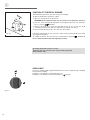
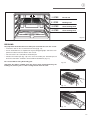
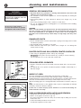
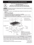
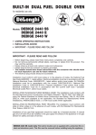
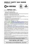
B U I LT- I N
GAS
OVEN
for residential use only
Model:
VEBIG 24 ..
• USERS OPERATING INSTRUCTIONS
• INSTALLATION ADVICE
• IMPORTANT - PLEASE READ AND FOLLOW
IMPORTANT - PLEASE READ AND FOLLOW
✓ Before beginning, please read these instructions completely and carefully.
✓ Do not remove permanently affixed labels, warnings, or plates from the product. This
may void the warranty.
✓ Please observe all local and national codes and ordinances.
✓ Please ensure that this product is properly grounded.
✓ The installer should leave these instructions with the consumer who should retain
for local inspector's use and for future reference.
✓ The electrical plug should always be accessible.
Installation must conform with local codes or in the absence of codes, the National Fuel
Gas Code ANSIZ223.1 - Iatest edition. Electrical installation must be in accordance with the
National Electrical Code, ANSI/NFPA70 - latest edition and/or local codes. IN CANADA:
Installation must be in accordance with the current CAN/CGA-B149.1 National Gas
Installation Code or CAN/CGA-B149.2, Propane Installation Code and/or local codes.
Electrical installation must be in accordance with the current CSA C22.1 Canadian
Electrical Codes Part 1 and/or local codes.
INSTALLATION IN MANUFACTURED (MOBILE) HOME: The installation must conform with
the Manufactured Home Construction and Safety Standard, Title 24 CFR, Part 3280 [formerly the Federal Standard for Mobile Home Construction and Safety, Title 24, HUD (Part
280)] or, when such standard is not applicable, the Standard for Manufactured Home
Installations, ANSI/NCSBCS A225.1, or with local codes where applicable.
INSTALLATION IN RECREATIONAL PARK TRAILERS: The installation must conform with
state or other codes or, in the absence of such codes, with the Standard for Recreational
Park Trailers, ANSI A119.5.
Installation of any gas-fired equipment should be made by a Iicensed plumber. A manual
shut-off valve must be installed in an accessible location in the gas line external to the
appliance for the purpose of turning on or shutting off gas to the appliance (In
Massachusetts such shutoff devices should be approved by the Board of State Examiners
of Plumbers & Gas Fitters).
Stainless steel models only: This built-in oven is supplied with a protective film
on steel and aluminium parts. This film must be removed before installing/using the
appliance.
WARNING: IF THE INFORMATION IN THIS MANUAL IS NOT
FOLLOWED EXACTLY, A FIRE OR EXPLOSION MAY RESULT
CAUSING PROPERTY DAMAGE, PERSONAL INJURY, OR DEATH.
✓ Do not store or use gasoline or other flammable vapors and liquids
in the vicinity of this or any other appliance.
✓ WHAT TO DO IF YOU SMELL GAS:
• Do not try to light any appliance.
• Do not touch any electrical switch; do not use any phone in your
building.
• Immediately call your gas supplier from a neighbor's phone.
Follow the gas supplier's instructions.
• If you cannot reach your gas supplier, call the fire department.
✓ Installation and service must be performed by a qualified installer,
service agency, or the gas supplier.
WARNING
NEVER use this appliance as a space heater to heat or warm the
room. Doing so may result in carbon monoxide poisoning and
overheating of the oven.
WARNING!
The Governor of California is required to publish a list of substances known to the state of California to cause
cancer or reproductive harm and requires businesses to warn customers of potential exposures to such substances.
WARNING!: Gas appliances contain or produce substances which can cause death or serious illness and
which are known to the State of California to cause cancer, birth defects or other reproductive harm.
To reduce the risk from substances in fuel or from fuel combustion, make sure this appliance is installed, operated, and maintained according to the manufacturer's instructions.
This appliance is designed and manufactured solely for the cooking of
domestic (household) food and is not suitable for any none domestic
application and therefore should not be used in a commercial environment.
The appliance guarantee will be void if the appliance is used within a none
domestic environment i.e. a semi commercial, commercial or communal
environment.
2
Dear Customer,
Thank you for having purchased and given your preference to our product.
The safety precautions and recommendations reported below are for your own
safety and that of others. They will also provide a means by which to make full use
of the features offered by your appliance.
Please preserve this booklet carefully. It may be useful in future, either to yourself or to others in the event that doubts should arise relating to its operation.
This appliance must be used only for the task it has explicitly been designed
for, that is for cooking foodstuffs. Any other form of usage is to be considered
as inappropriate and therefore dangerous.
The manufacturer declines all responsibility in the event of damage caused by
improper, incorrect or illogical use of the appliance.
DATA PLATE
CONVERSION LABEL
3
USER INSTRUCTIONS
IMPORTANT PRECAUTIONS AND RECOMMENDATIONS
After having unpacked the appliance, check to ensure that it is
not damaged.
In case of doubt, do not use it and consult your supplier or a professionally qualified technician.
Packing elements (i.e. plastic bags, polystyrene foam, nails,
packing straps, etc.) should not be left around within easy reach
of children, as these may cause serious injuries.
The packaging material is recyclable and is marked with the
recycling symbol
.
✓ Do not attempt to modify the technical characteristics of the
appliance as this may become dangerous to use.
✓ Do not carry out cleaning or maintenance operations on the
appliance without having previously disconnected it from the
electric power supply.
✓ After use, ensure that the knobs are in OFF position.
✓ Do not allow children or other incapable people to use the
appliance without supervision.
✓ During and after use of the oven, certain parts will become
very hot. Do not touch hot parts.
✓ Keep children away from the oven when it is in use.
✓ Stainless steel models only: This oven is supplied with a
protective film on steel and aluminium parts. This film must be
removed before installing/using the appliance.
✓ Fire risk! Do not store flammable material in the oven.
✓ Make sure that electrical cables connecting other appliances
in the proximity of the oven cannot become entrapped in the
oven door.
✓ Do not line the oven walls with aluminium foil. Do not place
shelves, broiler pan, pans or other cooking utensils on the
base of the oven chamber.
✓ The manufacturer declines all liability for injury to persons or
damage to property caused by incorrect or improper use of
the appliance.
✓ To avoid any possible hazard, the appliance must be installed
by qualified personnel only. Any repairs by unqualified persons
may result in electric shock or short circuit. In order to avoid
possible injuries to your body or to the appliance, do not
attempt any repairs by yourself. Such work should be carried
out by qualified service personnel only.
KEEP ATTENTION!!
STAND AWAY FROM THE CONTROL
PANEL LOUVERS (see figure above). HOT
AIR WHICH ESCAPES CAN CAUSE
BURNS TO HANDS, FACE, END/OR EYES.
✓ Important! The use of suitable protective clothing/gloves is
recommended when handling, installing or cleaning of this
appliance.
✓ Danger of burns! The oven and cooking accessories may
become very hot during operation. Make sure children are
kept out of reach and warn them accordingly. To avoid burns
use kitchen clothes and gloves when handling hot parts or
utensils.
✓ Stand away from the oven when opening oven door. Hot air or
steam which escapes can cause burns to hands, face, and/or
eyes.
4
✓ Never clean the oven with a high-pressure steam cleaning
device, as it may provoke a short circuit.
✓ This appliance is intended for use in your household. Never
use the appliance for any other purpose!
✓ If you should decide not to use this appliance any longer (or
decide to substitute an older model), before disposing of it, it
is recommended that it be made inoperative in an appropriate
manner in accordance to health and environmental protection
regulations, ensuring in particular that all potentially hazardous parts be made harmless, especially in relation to children who could play with old appliances.
Remove the door before disposal to prevent entrapment.
✓
WARNING!!
This appliance shall not be used for space heating. This
information is based on safety considerations.
✓ Keep appliance area clear and free from combustible materials, gasoline, and other flammable vapors.
✓ The misuse of oven door (e.g. stepping, sitting, or leaning on
them) can result in potential hazards and/or injuries.
IMPORTANT PRECAUTIONS AND RECOMMENDATIONS FOR USE OF ELECTRICAL
APPLIANCES
Use of any electrical appliance implies the necessity to follow a
series of fundamental rules. In particular:
✓ Never touch the appliance with wet hands or feet;
✓ Do not operate the appliance barefooted;
✓ Do not allow children or disabled people to use the appliance
without your supervision.
The manufacturer cannot be held responsible for any damages
caused by improper, incorrect or unreasonable use of the
appliance.
5
�
control panel
Fig. 1.1
1
CONTROL PANEL
1.
2.
3.
4.
(Fig. 1.1)
Gas oven/gas broil control knob
Oven light control knob
Cooling fan warning light
60’ alarm control knob
4
3
2
CAUTION:
Gas appliances produce heat and humidity in
the environment in which they are installed.
Ensure that the cooking area is well ventilated
following national/local codes.
When the cooling fan failure warning light is OFF the cooling fan
motor is correctly operating.
The oven can be used.
Operate the oven as
per instruction manual.
When the cooling fan failure warning light is lighted this indicates
the malfunctioning of the cooling fan motor.
1. Close the supply line
manual shut-off valve.
Disconnect the oven from the gas/electrical
mains and contact the After-Sales Service.
Shut-off valve
"close" position
The oven cannot be used.
2. Disconnect the 3-prong
ground plug.
3. Contact the After-Sales
Service.
6
60’ alarm knob
�
MINUTE COUNTER (fig. 2.1)
The minute counter is a timed acoustic warning device which can be set for a
maximum of 60 minutes.
The knob (Fig. 2.1) must be rotated clockwise as far as the 60 minute position and
then set to the required time by rotating it anticlockwise.
IMPORTANT WARNING: This is only a mechanical timer.
Remember to turn off the oven/broil manually.
Fig. 2.1
7
�
how to use the gas oven
ATTENTION: the oven becomes
very hot during operation.
ATTENTION: the oven door
becomes very hot during operation.
GENERAL FEATURES
The gas oven is provided with two burners:
a) Oven burner, mounted on the lower part of the oven (11000 BTU/hr)
b) Broil burner, mounted on the upper part of the oven (7000 BTU/hr).
KEEP CHILDREN AWAY.
WARNING:
The door is hot, use the handle.
USING THE OVEN FOR THE FIRST TIME
It is advised to follow these instructions:
VERY IMPORTANT
The oven/broil shall be used always
with the oven door closed.
– Furnish the interior of the oven by placing the wire racks as described at chapter
“Cleaning and maintenance”.
– Insert shelves and tray.
) to eliminate
– Turn the oven on to the maximum temperature (position
possible traces of grease from the oven burner. The same operation should be
followed for broil burner.
– Switch off the electrical supply, let the oven cool down, then clean the interior
of the oven with cloth soaked in water and detergent (neutral) then dry carefully.
OVEN BURNER
It carries out normal “oven cooking”.
The gas flow to the burner is regulated by a thermostat which allow to maintain the
oven temperature constant.
The control of the temperature is assured by a thermostatic probe positioned inside the
oven.
The probe must be always kept in its housing, in a clean condition, as an incorrect position or encrustment may cause an alteration in the control of the temperature.
Fig. 3.1
GAS OVEN SETTING
8
Number printed on
the control panel
Temperature
in °F
Corresponding
temperature
in °C
200
93
250
121
300
149
350
177
400
204
450
232
500
260
550
288
OVEN THERMOSTAT
The numbers printed on the control panel (fig. 3.1) indicate the increasing oven temperature value (°F). To regulate the temperature, set the chosen number onto the knob
indicator.
The position
serves only to turn on the broil burner.
N.B. When the oven is not being used, set the gas knob to the
position and
also close the gas shut-off valve placed on the main gas supply line.
햴
IGNITION OF THE OVEN BURNER
The thermostat allows the automatic control of the temperature.
The gas delivery to the oven burner is controlled by a two way thermostatic tap (oven
and broil burners) with flame-failure device.
To light the oven burner operate as follows:
1) Open the oven door to its full extent.
WARNING: Risk of explosion! The oven door must be open during this operation.
2) Press the oven control knob right down and, keeping it pressed, turn counter-clockwise (fig. 3.2) to max position
.
Fig. 3.2
3) Release the knob and check the oven burner has lit; if not, turn the knob clockwise
back to OFF and repeat the procedure from step 2.
4) Once the oven burner has lit, close the oven door slowly and adjust the burner
according to the power required.
If the flame extinguishes for any reason, the safety valve will automatically shut off the
gas supply to the burner.
To re-light the burner, first turn the oven control knob to position
, wait for at least
1 minute and then repeat the lighting procedure.
Attention: the oven door becomes very hot during operation.
Keep children away.
OVEN COOKING
Before introducing the food, preheat the oven to the desired temperature.
For a correct preheating operation, it is advisable to remove the tray from the oven and
introduce it together with the food, when the oven has reached the desired temperature.
Check the cooking time and turn off the oven 5 minutes before the theoretical time to
recuperate the stored heat.
9
햴
IGNITION OF THE BROIL BURNER
The broil burner generates the infra-red rays for broiling.
To light the broil burner operate as follow:
1) Open the oven door to the full extent.
WARNING: Risk of explosion! The oven door must be open during this operation.
2) Press the oven control knob right down and, keeping it pressed, turn clockwise
(fig. 3.3) to the
position.
3) Release the knob and check the broil burner has lit; if not, turn the knob
counterclockwise back to OFF and repeat the procedure from step 2.
4) Once the broil burner has lit, close the oven door slowly.
Fig. 3.3
If the flame extinguishes for any reason, the safety valve will automatically shut off the
gas supply to the burner.
To re-light the burner, first turn the oven control knob to position
, wait for at
least 1 minute and then repeat the lighting procedure.
Do always broil with oven door closed.
Attention: the oven door becomes very hot during operation.
Keep children away.
OVEN LIGHT
The oven is equipped with a light that illuminates the oven to enable visually controlling
the food that is cooking.
This light is controlled by a switch knob (Fig. 3.4).
To light the oven lamp turn the knob clockwise to
position.
Fig. 3.4
10
햴
1° STEP
Do not use
2° STEP
Broiling level
3° STEP
Oven cooking level
4° STEP
Oven cooking level
Fig. 3.5
BROILING
Very important: the broil burner must always be used with the oven door closed.
– Position the shelf on the second level from the top (fig. 3.5).
– Turn on the broil burner, as explained in the preceding paragraphs and let the oven
preheat for about 5 minutes with the door closed.
– Place the food to be cooked above the broiler pan.
– Introduce the broiler pan (fig. 3.6) in the oven. The broiler pan should be placed
above the shelf and it should be centered with the broil burner (fig. 3.5).
Do not broil without using the broiling pan.
Fig. 3.6
Important: Use always suitable protective gloves when inserting/removing the
broiling pan, shelves, pans or other cooking utensils from the oven.
WRONG
Fig. 3.7
CORRECT
Fig. 3.8
11
�
cleaning and maintenance
GENERAL RECOMANDATION
WARNING
VERY IMPORTANT
Before any operation of maintenance
disconnect the appliance from the
electrical mains supply.
Do not use a steam cleaner
because the moisture can get into
the appliance thus make it unsafe.
✓ Important: Before any operation of cleaning and maintenance disconnect the
appliance from the electrical supply.
✓ It is advisable to clean when the appliance is cold and especially for cleaning the
enamelled parts.
✓ Avoid leaving alkaline or acidic substances (lemon juice, vinegar, etc.) on the
surfaces.
✓ Avoid using cleaning products with a chlorine or acidic base.
✓ The use of suitable protective clothing/gloves is recommended when handling,
cleaning this appliance.
WARNING
When correctly installed, your product meets all safety requirements laid down for
this type of product category. However special care should be taken around the
rear or the underneath of the appliance as these areas are not designed or
intended to be touched and may contain sharp or rough edges, that may cause
injury.
ENAMELLED PARTS
✓ All the enamelled parts must be cleaned with a sponge and soapy water or other
non-abrasive products.
✓ Dry preferably with a microfibre or soft cloth.
✓ Acidic substances like lemon juice, tomato sauce, vinegar etc. can damage the
enamel if left too long.
PAINTED PARTS AND SILK-SCREEN PRINTED SURFACES
✓ Clean using an appropriate product. Always dry thoroughly.
IMPORTANT: these parts must be cleaned very carefully to avoid scratching
and abrasion.
You are advised to use a soft cloth and neutral soap.
STAINLESS STEEL ELEMENTS
G
✓ Stainless steel parts must be rinsed with water and dried with a soft and clean
cloth.
✓ For difficult dirt, use a specific non-abrasive product available commercially or a
little hot vinegar.
INSIDE OF OVEN
Fig. 4.1
Do not use this step
Safety
catch
The oven should always be cleaned after use when it has cooled down.
The cavity should be cleaned using a mild detergent solution and warm water.
Suitable proprietary chemical cleaners may be used after first consulting with the manufacturers recommendations and testing a small sample of the oven cavity.
Abrasive cleaning agents or scouring pads/cloths should not be used on the cavity surface.
NOTE: The manufacturers of this appliance will accept no responsibility for damage
caused by chemical or abrasive cleaning.
Let the oven cool down and pay special attention no to touch the hot heating elements inside the oven cavity.
OVEN ACCESSORIES INSTALLATION AND REMOVAL
Fig. 4.2
12
– Hang up the wire racks “G” on the oven walls (fig. 4.1).
– Slide in, on the guides, the shelf etc. (fig. 4.2).
The rack must be fitted so that the safety catch, which stops it sliding out, faces the
inside of the oven.
– Position the broiler pan above the oven shelf.
– To dismantle, operate in reverse order.
햵
OVEN DOOR
The internal glass of the oven door can be easily removed for cleaning by unscrewing
the two lateral fixing screws (fig. 4.3).
Do not use harsh abrasive cleaners or sharp metal scrapers to clean the oven door
glass since they can scratch the surface, which may result in shattering of the
glass.
Do not store flammable material in the oven.
REPLACING THE OVEN LIGHT
Before any maintenance is started involving electrical parts of the appliance, it must be
disconnected from the power supply.
Fig. 4.3
– Let the oven cavity and the broil burner cool down;
– Switch off the electrical supply;
– Remove the protective cover;
– Unscrew and replace the bulb with a new one suitable for high temperatures (300°C570°F) having the following specifications: 120V 60 Hz, 15W, E14.
– Refit the protective cover
NOTE: Oven bulb replacement is not covered by your guarantee
L
REMOVING THE OVEN DOOR
To facilitate oven cleaning, it is possible to remove the door.
Please follow the instructions carefully:
Fig. 4.4
– Open the door completely.
– Push down the lever “L” and, keeping it in this position, slowly close the door in
order to block the hinge (fig. 4.4).
– Grip the door (as indicated in fig. 4.5) and, while closing it, release the two hinges as
shown in fig. 4.6.
– Rest the door on a soft surface.
DOOR ASSEMBLY
– Grip the door with your hands placed near the hinges and raise the levers “H” with
your forefingers (fig. 4.6)
– Insert the hinges in their position until levers “H” are hooked.
– Open the door completely to obtain the release of levers “L”.
Fig. 4.5
H
Fig. 4.6
13
햵
DO’S AND DO NOT’S
• Do always broil with the oven door closed.
• Do read the user instructions carefully before using the oven for first time.
• Do allow the oven to heat for one and a half hours, before using for the first time, in
order to expel any smell from the new oven insulation, without the introduction of
food.
• Do clean your oven regularly.
• Do remove spills as soon as they occur.
• Do always use oven gloves when removing food shelves and trays from the oven.
• Do not allow children near the oven when in use.
• Do not allow fat or oils to build up in the oven base, or oven accessories.
• Do not place cooking utensils or plates directly onto the oven base.
• Do not broil without using the broiler pan.
• Do not place hot enamel parts in water. Leave them to cool first.
• Do not allow vinegar, coffee, milk, saltwater, lemon or tomato juice to remain in
contact with enamel parts (i.e. inside the oven).
• Do not use abrasive cleaners or powders that will scratch the surface of the stainless
steel and the enamel.
• Do not attempt to repair the internal workings of your oven.
• VEBIG 24 SS model only: Do remove the protective film before the first use.
• Fire risk! Do not store flammable material in the oven.
FOR YOUR SAFETY
Under no circumstances should any external covers be removed for servicing or
maintenance except by suitably qualified personnel.
14
INSTALLATION INSTRUCTIONS
WARNING!
THIS APPLIANCE HAS TO BE INSTALLED BY A QUALIFIED INSTALLER.
Improper installation, adjustment, alteration, services, or maintenance can cause injury or property damage. Consult a
qualified installer, service agent, or the gas supplier.
IMPORTANT: The use of suitable protective clothing/gloves is recommended when handling, installing of this appliance.
CAUTION !
Some cabinets and building materials are not designed to withstand the heat produced by the normal safe operation of the appliance. Dis-coloration or damage, such as delamination, may occur.
To prevent possible damage to cabinets and cabinet finishes, use only materials and finishes that will withstand temperature up to
190°F (88°C), and that are moisture resistant.
When cabinets are covered with laminates, an appropriate heat-resistant adhesive must be used.
Consult your cabinet manufacturer for proper specifications.
The cabinet must have solid sides, back and bottom. The bottom must be solid either at floor level or with the bottom edge of the
cutout. Any openings around the gas or electrical outlets must be sealed. All cabinet openings must be sealed at the time of installation to prevent drafts. Drafts will affect safe use of the oven.
TOOLS NEEDED FOR INSTALLATION (NOT SUPPLIED WITH THE APPLIANCE)
Screwdriver
Wrench
Suitable protective
gloves
T-handle
wrench
Angled
hexagon key
Adjustable
wrench
Adjustable
pliers
Tape
measure
Pencil
Drill
15
GENERAL INFORMATION
1. Installation must conform with local codes or, in the
absence of local codes, with the National Fuel Gas Code,
ANSI Z223.1-Latest Edition.
2. Installation in manufactured (mobile) home: installation must
conform with the Manufactured Home Construction and
Safety Standard, Title 24 CFR, Part 3280 [formerly the
Federal Standard for Mobile Home Construction and
Safety, Title 24, HUD (Part 280)] or, when such standard is
not applicable, the Standard for Manufactured Home
Installations, ANSI/NCSBCS A225.1, or with local codes
where applicable.
3. Installation in Recreational Park Trailers: installation must
conform with state or other codes or, in the absence of such
codes, with the Standard for Recreational Park Trailers,
ANSI A119.5.
4.
WARNING!!
This appliance shall not be used for space heating. This
information is based on safety considerations.
5. AlI openings in the wall behind the appliance and in the floor
under the appliance shall be sealed.
6. Keep appliance area clear and free from combustible materials, gasoline, and other flammable vapors.
7. Do not obstruct the flow of combustion and ventilation air.
8. Disconnect the electrical supply to the appliance before servicing.
9. When removing appliance for cleaning and/or service;
A. Shut off gas at main supply.
B. Disconnect AC power supply.
C. Disconnect gas line to the inlet pipe.
D. Carefully lift appliance out of cabinet cutout.
CAUTION: Use care in handling.
10. Electrical Requirement
Electrical installation should comply with national and local
codes.
11. Air Supply and Ventilation
The installer must refers to local/national codes.
12. Gas Manifold Pressure
Natural gas - 4.0” W.C.P.
LP/Propane - 11.0” W.C.P.
13. The misuse of oven door (e.g. stepping, sitting, or leaning on
them) can result in potential hazards and/or injuries.
16
WARNING!!
ELECTRICAL GROUNDING INSTRUCTIONS
The oven must be electrically grounded in accordance with
local codes or, in the absence of local codes, with the
National Electrical Code, ANSI/NFPA No 70-latest edition.
Installation should be made by a Iicensed electrician.
FOR PERSONAL SAFETY, THIS APPLIANCE MUST BE
PROPERLY GROUNDED.
This appliance is equipped with a three-prong grounding plug
for your protection against shock hazard and should be
plugged directly into a properly grounded socket. Do not cut
or remove the grounding prong from the plug.
For personal safety, this appliance must be properly
grounded.
Do not under any circumstances cut or remove the third
(ground) prong from the power plug.
REPLACEMENT PARTS
Only authorized replacement parts may be used in performing
service on the oven. Replacement parts are available from
factory authorized parts distributors. Contact the nearest parts
distributor in your area.
�
installation
INSTALLATION TO THE CABINET
Taking care NOT to lift the
oven by the door handle.
Cutout dimensions (fig. 5.3):
22" 11/64
24"
• width = 24" (609.5 mm);
• depth = 21" 5/8 (550 mm);
• depth = 23" 3/16 (589.5 mm) with gas pressure regulator
fitted;
• height = 24" (609.5 mm);
• oven frame depth = 25/32" (20 mm);
(609.5 mm)
Oven dimensions (fig. 5.1):
21"
4
(553 9/64
mm
)
2
(60 4"
9.5
mm
)
• width = 22" (559 mm);
• depth = 23" (584 mm) minimum from front corner of cutout;
• height = 23" (584);
/8
"5
21 m)
0m
(55
6
/1
" 3 m)
3
2
m
5
9.
8
(5
(563.2 mm)
32"
25/ m)
m
(20
This oven may be installed to 24" minimum (609.5 mm) wide
cabinets
re
su
es
r
s p ted
ga r fit
th
to
wi ula
g
e
r
Fig. 5.1
IMPORTANT NOTE: THE BOTTOM OF CUTOUT SHALL
BE AT LEAST 22" 5/8 (574.4 mm) FROM THE FLOOR. DO
NOT INSTALL THE OVEN BENEATH THE WORK
COUNTER.
On the lover side, the oven must lay on a support standing
the oven weight. Oven support surface MUST be solid.
All openings in the wall or floor where the oven is to be
installed MUST be sealed. Oven location should be away
from strong draft areas, such as windows, doors and strong
heating vents.
For SAFETY CONSIDERATIONS the oven SHALL BE FASTENED to the cabinet with four (4) SUITABLE screws (not
supplied with the unit) through the holes in the trim (see fig.
5.2). The unit should be leveled properly before being
secured to the cabinet.
Fig. 5.2
17
햶
cut-ou
t
Gas line opening:
Provide a suitable hole on the bottom of
cutout. The centre of hole shall be 10"
1/16 (255.8 mm) from the centre of
cutout to the left side and 20" 35/64 (522
mm) from the front corner of cutout to
the back.
width
22"
(559 m
m)
um epth
nimut d "
)
i
m -o
2 3 mm
t
cu
84
cut-out height
23"
(584 mm)
minimum height
from the floor
22" 5/8
(574.4 mm)
(5
Fig. 5.3
Provide a hole for
gas connection to
1/2" diameter
pipe fitting.
Provide hole
for electrical
connection in
this area
/64 )
35
m
"
20 22 m
(5
um 16
)
nim" 5/ mm
i
m 20
5
5.
(51
=
=
Area for
electrical
connection
=
=
Fig. 5.4
18
minimum
7" 7/8
(200 mm)
10"
(255 1/16
.8 m
m)
1" 1/
(31.8 4
mm)
Grounded outlet:
The electric cord with 3-prong ground
plug has a length of 48” (1220 mm).
Grounded outlet should be located in an
area 7" 7/8 (200 mm) below the bottom
of cutout and only on the right side of the
cabinet (from the centre to the right side
of the cabinet).
A suitable hole has to be provided on the
bottom of the cutout, in an area positioned on the right rear corner (1" 1/4
[31.8 mm] maximum from the right side
of cutout and from the rear corner to
maximum 20" 5/16 (515.5 mm) from the
front corner of cutout), to pass the appliance cable.
�
gas connection
All gas connections must be made according to national and local codes. This gas
supply (service) line must be the same size or greater than the inlet line of the
appliance. Sealant on all pipe joints must be resistant to the action of LP/Propane
gas.
Explosion Hazard
The oven is equipped for the use with NATURAL gas. It is design-certified by CSA
International for NATURAL and L.P. gases with appropriate conversion.
The model/serial rating plate, located on the back of the oven, has information on
the type of gas that can be used. If this information does not agree with the type of
gas available, check with the local gas supplier. See page 23 for L.P. gas conversion
inctructions.
Use a new CSA or UL approved
gas supply line.
Install a shut-off valve.
Securely tighten all gas connections.
If connected to LP, have a qualified person make sure gas pressure does not exceed 14" water
column.
Examples of a qualified person
include licensed heating personnel, authorized gas company personnel, and authorized
service personnel.
1. Manual Shut-off Valve
(fig. 6.1):
A manual shut-off valve must be installed in an accessible location in the gas line
external to the appliance for the purpose of turning on or shutting off gas to the
appliance (In Massachusetts such shutoff devices should be approved by the Board
of State Examiners of Plumbers & Gas Fitters). This valve should be located in the
same room as the oven and should be in a location that allows ease of opening and
closing (in a position where it can be reached quickly in the event of an emergency).
Do not block access to the shutoff valve. The valve is for turning on or shutting off
gas to the appliance.
Failure to do so can result in
death, explosion, or fire.
Shutoff valve
“open” position
To oven
Gas supply line
Fig. 6.1
2. Pressure Regulator:
a) All heavy duty, commercial type cooking equipment must have a pressure regulator
on the incoming service line for safe and efficient operation, since service pressure
may fluctuate with local demand.
Before installing the regulator mount the 3/8” NPT (conical) male connector to the
regulator (see picture 6.2a). Gasket supplied have to be placed between 3/8” NPT
(conical) connector/manifold male pipe fitting (see picture 6.2b).
The regulator supplied with this oven must be installed before any gas connections
are made.
Use supplied pressure regulator only.
19
햷
PRESSURE REGULATOR INSTALLATION
햳
STEP 1
Mount the 3/8” NPT (conical) male connector to the pressure
regulator and tighten by using a wrench.
Do not over tighten the connector.
Over tightening may crack regulator.
LOCK
Arrow
Fig. 6.2a
STEP 2
Assemble the 3/8” NPT connector + pressure regulator group to the manifold interposing the gasket supplied. The regulator
cover must be oriented toward the back of the cabinet.
IMPORTANT: use two spanners to tighten the connection.
Regulator cover
Fig. 6.2b
20
햷
GAS CONNECTION SPECIFICATION
To oven
Oven
manifold
Manifold
male
pipe fitting
Gasket
3/8” NPT (conical)
male
1/2” G cylindrical
(ISO 228-1) male
Manifold
test point
pressure
1/8” NPT
1/2” G cylindrical
(ISO 228-1) female
Connector
3/8” NPT
female
To mains
connection
Pressure
regulator
3/8” NPT
female
Arrow
WARNING: check the right positioning
of the gas regulator. The arrow on the
back of the gas regulator must be
oriented toward the connector.
Fig. 6.3
21
햷
b) Any conversion required must be performed by your dealer or a qualified licensed
plumber or gas service company. Please provide the service person with this
manual before work is started on the oven. (Gas conversions are the responsibility
of the dealer or end user.)
c) This oven can be used with NATURAL or LP/PROPANE gas. It is shipped from
the factory adjusted for use with NATURAL gas.
d) Manifold pressure should be checked with a manometer; NATURAL gas requires
4.0” W.C.P. and LP/PROPANE requires 11.0” W.C.P. (see figure below).
Incoming line pressure upstream from the regulator must be 1” W.C.P. higher than
the manifold pressure in order to check the regulator.
The regulator used on this oven can withstand a maximum input pressure of 1/2
PSI (14.0” W.C.P). If the line pressure is in excess of that amount, a step-down
regulator will be required.
To oven
Screw
Manifold
test point
pressure
1/8” NPT
Unscrew
To mains
connection
Fig. 6.4
e) The appliance, its individual shut-off valve, and pressure regulator must be
disconnected from the gas supply piping system during any pressure testing of
that system at pressures in excess of 1/2 PSI (3.5 kPa).
f) The appliance must be isolated from the gas supply piping system by closing its
individual manual shut-off valve during any pressure testing of the gas supply
piping system at test pressure equal to or less than 1/2 PSI (3.5 kPa).
3. Flexible Connections:
If local codes permit, CSA design-certified, flexible metal appliance connector is
recommended for connecting this oven to the gas supply line. Do Not kink or damage
the flexible connector when moving the oven. The pressure regulator has 3/8" NPT
female pipe threads.You will need to determine the fittings required, depending on
the size of your gas supply line, flexible metal connector and shutoff valve.
4. Rigid Pipe Connections:
If rigid pipe is used as a gas supply line, a combination of pipe fittings must be used
to obtain an in-line connection to the oven. All strains must be removed from the
supply and fuel lines so oven will be level and in line.
• Use joint compounds and gaskets that are resistant to action of natural or propane
gas on all male pipe threads.
• Do not over tighten gas fitting when attaching to pressure regulator. Over tightening
may crack regulator.
22
햷
5. Leak Testing:
IMPORTANT: Leak testing of the appliance shall be conducted as follows:
• After final gas connection is made, turn on manual gas valve and test all
connections in gas supply piping and appliance for gas leaks with a soapy water
solution. During this test all appliance gas valves have to be closed.
• In order to avoid property damage or serious personal injury , never use a Iighted
match. If a leak is present, tighten joint or unscrew, apply more joint compound,
tighten again and retest connection for leak.
CONVERSION TO LP/PROPANE GAS
Every oven is provided with a set of injectors for the various types of gas.
Select the injectors to be replaced according to the "INJECTORS TABLE".
The nozzle diameters, expressed in hundredths of a millimetre, are marked on the
body of each injector.
SETTING THE PRESSURE REGULATOR
1. Unscrew the regulator cover;
2. Unscrew the A component, reverse and screw it according to the LP/PROPANE
regulation.
1
2
A
LP/PROPANE
REGULATION
NATURAL GAS
REGULATION
Fig. 6.5
INJECTORS TABLE
NOMINAL
POWER
REDUCED
POWER
LP/PROPANE
11” W.C.P.
NATURAL GAS
4” W.C.P.
BTU/hr
BTU/hr
Ø injector
[1/100 mm]
Ø injector
[1/100 mm]
Oven burner
11000
1500
96
164
Broil burner
7000
–
78
130
BURNERS
23
햷
OPERATIONS TO BE EXECUTED FOR THE REPLACEMENT OF
THE INJECTORS OF THE OVEN AND BROIL BURNERS
a) oven burner
– Lift and remove the lower panel inside the oven.
– Remove the burner securing screw (fig. 6.6)
– Withdraw the burner as shown in figure 6.7 and rest it inside the oven. Take care not
to damage the wire to the ignition electrode and the safety valve probe.
Fig. 6.6
– Using a 7 mm box spanner, unscrew the injector (indicated by the arrow in fig. 6.7)
and replace it by the proper one according to the kind of gas.
Then replace the burner repeating the above steps in reverse order.
b) broil burner
– Remove the burner by unscrewing the front screw (fig. 6.8).
Gently suspend the burner as shown in figure 6.9. Be careful not to damage the
wire of the electric ignition and the probe of the safety valve.
– Using a 7 mm box spanner, replace the injector (indicated by the arrow in fig. 6.9)
by the proper one according to the kind of gas.
Fig. 6.7
Fig. 6.8
Fig. 6.9
24
– Replace the burner repeating the above steps in reverse order.
햷
ADJUSTMENT OF THE OVEN BURNER MINIMUM
This needs to be done only for the oven burner (the broil is a fixed capacity) by acting
on the thermostat in the following way:
– Turn on the burner by setting the thermostat knob on position
.
– Remove the knob and unscrew the by-pass screw "G" (fig. 7.12) about three times by
passing a small flat screwdriver (Ø 3 mm blade, 100 mm length) through the panel
opening.
– Re-mount the knob and let the oven heat up for about 10 minutes, then bring the knob
to position
(minimum) to operate the thermostat by-pass
Fig. 6.10
G
– After having removed the knob again and being very careful not to turn the tap rod,
slowly screw the by-pass screws “G” (fig. 6.10) until you obtain a flame of 3-4 mm in
height.
N.B. For LP/PROPANE gas the by-pass screw must be fixed thoroughly.
After regulation repeat the operations indicated in paragraph “2. Pressure regulator” at
page 19.
If the oven has been disconnected and then connected again to the gas supply line
repeat the operations indicated in paragraph “5. Leak Testing” at page 23.
IMPORTANT:
After conversion to LP/PROPANE gas has been carried out affix near the data plate, the
conversion label supplied and also affix a conversion label at page 3 of this instruction
manual.
25
쐆
electrical connection
WARNING
If codes permit and a separate ground wire is used, it is recommended that a
qualified electrician determine that the ground path is adequate.
Check with a qualified electrician if you are not sure whether the oven is properly grounded.
Do Not ground to a gas pipe.
A 120-volt, 60-Hz, AC-only, 15-ampere, fused electrical supply is required. A time-delay
fuse or circuit breaker is recommended. It is recommended that a separate circuit serving only this appliance be provided.
Electrical Shock Hazard
Plug into a grounded 3-prong
outlet.
Do not remove ground prong.
Do not use an adapter.
Failure to follow these instructions
can result in death, fire, or
electrical shock.
The outlet must be checked by a qualified electrician to see if it is wired with correct
polarity.
This appliance, when installed, must be electrically grounded in accordance with local
codes.
Recommended ground method
For your personal safety, this oven must be grounded. This oven is equipped with a 3prong ground plug. To minimize possible shock hazard, the cord must be plugged into
a mating 3-prong ground-type outlet, grounded in accordance with the National
Electrical Code ANSI/NFPA 70 latest edition or Canadian Electrical Code (CSA) and
local codes and ordinances. If a mating outlet is not available, it is the personal responsibility and obligation of the customer to have a properly polarized and grounded, 3prong outlet installed by a qualified electrician.
WARNING
VERY IMPORTANT
Before any operation of maintenance
disconnect the appliance from the
electrical mains supply.
3-prong polarized
ground-type outlet
3-prong
ground plug
power
supply cord
ground
prong
Fig. 7.1
26
햸
ELECTRIC DIAGRAM
27
The manufacturer cannot be held responsible for possible inaccuracies due to printing or transcription errors in
the present booklet.
The manufacturer reserves the right to make all modifications to its products deemed necessary for manufacture
or commercial reasons at any moment and without prior notice, without jeopardising the essential functional and
safety characteristics of the appliances.
Cod. 1103642 - ß1