1
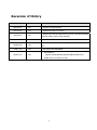
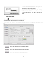
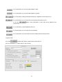
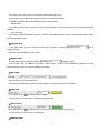
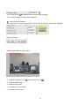
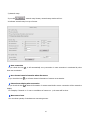
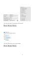
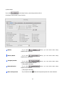
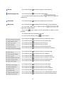
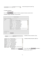
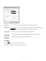
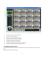
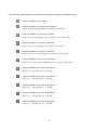
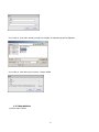
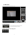
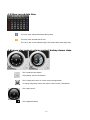
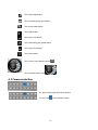
CMS Software
User’s Manual (v3.06)
This product is made by advanced technology and passed reliability and compatibility test. Product quality can be
guaranteed.
This is an operation guide for CMS user.
This guide gives you CMS way of configuration of system program.
If you are first user of CMX DVR, even though you are experienced with similar products like this,
recommend you to read this manual carefully and follow the instructions inside before using this product.
CAUTION
The copyright of this manual belongs to original manufacturer.
It is prohibited to copy this manual without permission.
We do not guarantee, if your system is damaged by your mis-using disapproval components or
mis-operation.
If you have any problems or questions with our product, please contact the dealer you bought
from or original manufacturer.
If you need to open the system for modification or repairing, it is recommended that you have to
request an engineer’s assistance by contacting the dealer you bought it from or original
manufacturer.
CMS is a registered trademark of original manufacturer DVR system.
This product has certification for domestic and industrial use. Also, it has taken CE for Europe,
FCC for the U.S.
2
we
Symbols and Letters used in this Manual
Importance mark : Arrangement of items to be considered for completing work
Additional information or tip to avoid in order to completing work
Mouse left button click
Mouse left button double-click
Mouse right button click
3
Reversion of History
Date
Rev. No
Description
2007-03-21
3.00
Creation of the document
2007-05-10
3.01
Modified the part of contents
2007-09-12
3.02
2007-11-05
3.03
2008-03-18
3.04
2008-1-19
3.05
Modified the mouse image and the part of contents(FS-Wizard,
Schedule Setup, Sensor Setup, Backup)
Add External Device
Add CMS viewer & Router setting, Modify Backup part and
ETC.
Add HSTool and HSVIEWER
- Add Ipcamera
2009-07-10
3.06
Support Model(IDP2000/IxP4000/INS2000/IGP1030)
- Modify Server List Menu on CMS
4
Contents
Reversion of History..................................................................................................................4
Part 1. Network Solution .....................................................................................................................8
Support Model ............................................................................................................................9
1. CMS .................................................................................................................................... 10
1.1 Time check ................................................................................................................................ 10
1.2 Search, screen capture, setup, voice communication, E-Map .......................................................... 11
1.3 Server list indication.................................................................................................................... 11
1.4 Program shutdown, volume, PTZ control, server connection & disconnection ................................... 14
1.5 Screen division, full screen and switching...................................................................................... 15
1.6 LCD window and log ................................................................................................................... 17
1.7 Single channel search, network recording and preset ..................................................................... 17
1.8 Authentication ............................................................................................................................ 18
1.9 Screen capture ........................................................................................................................... 19
1.10 Server list................................................................................................................................. 21
1.10.1 Server connection............................................................................................................ 23
1.10.2 Server disconnection........................................................................................................ 24
1.10.3 Connect all servers .......................................................................................................... 24
1.10.4 Watching video ............................................................................................................... 25
1.10.5 Not watching video.......................................................................................................... 25
1.11 Server list use........................................................................................................................... 26
1.11.1 Server addition................................................................................................................ 28
1.11.2 Server information change ............................................................................................... 29
1.11.3 Server deletion ................................................................................................................ 29
1.12 Single channel search................................................................................................................ 30
1.12.1 Single channel search ...................................................................................................... 31
1.13 Preset ...................................................................................................................................... 32
1.13.1 Add preset ...................................................................................................................... 34
1.13.2 Preset information change................................................................................................ 35
1.13.3 Delete preset .................................................................................................................. 36
1.14 Setup....................................................................................................................................... 36
1.14.1 Local setup ..................................................................................................................... 37
1.14.2 Remote setup.................................................................................................................. 51
5
1.15 Search ..................................................................................................................................... 51
1.16 Audio communication ................................................................................................................ 51
1.17 EMap ....................................................................................................................................... 52
2. Use of Web Client.................................................................................................................. 53
2.1 Divided Screen Control................................................................................................................ 55
2.2 Automatic Conversion Button....................................................................................................... 57
2.3 Monitoring of Remote Image ....................................................................................................... 57
2.3.1 Configuration of Remote Image Monitoring Screen............................................................... 57
2.3.2 Remote Control ................................................................................................................. 57
2.3.3 Image Channel Entire Screen ............................................................................................. 58
2.4 Storage of Remote Monitoring Image ........................................................................................... 58
2.5 Remote PTZ Control and Volume Control ...................................................................................... 58
2.6 Two-way Audio ........................................................................................................................... 59
3. PDA viewer ........................................................................................................................... 61
3.1 Specification .............................................................................................................................. 61
3.2 Execution & the Beginning-Screen................................................................................................ 62
3.3 Server-List Registration ............................................................................................................... 63
3.4 Connection & Monitoring ............................................................................................................. 64
3.5 Remote Search........................................................................................................................... 66
Part 2. E-Map................................................................................................................................. 68
1. E-Map ................................................................................................................................. 69
1.1 Time check ................................................................................................................................ 69
1.2 Map management....................................................................................................................... 69
1.2.1 Map addition..................................................................................................................... 71
1.2.2 Map deletion..................................................................................................................... 72
1.3 Selection of server ...................................................................................................................... 73
1.4 Log ........................................................................................................................................... 74
1.5 Setup ........................................................................................................................................ 74
1.6 Map setup.................................................................................................................................. 76
1.6.1 Map setup ........................................................................................................................ 77
1.7 Map menu.................................................................................................................................. 79
Part 3. Backup & Backup Viewer ....................................................................................................... 82
1 Basket Backup ....................................................................................................................... 83
1.1 Make basket backup files ............................................................................................................ 84
2. Camera Backup..................................................................................................................... 86
2.1 make basket backup files ............................................................................................................ 87
3. Backup viewer....................................................................................................................... 89
6
3.1 Time, playback speed check. ....................................................................................................... 89
3.2 Opening backup data, motion video storing, printing. .................................................................... 89
3.2.1 Printing ............................................................................................................................ 90
3.3 Video effect................................................................................................................................ 92
3.4 Date indication of backup data..................................................................................................... 93
3.5 Playback control, volume control, closing backup viewer ................................................................ 93
3.6 Camera selection. ....................................................................................................................... 95
3.7 Playback zone selection............................................................................................................... 95
3.8 Watching video........................................................................................................................... 96
4. CMS Viewer .......................................................................................................................... 97
4.1 Time, Play Speed........................................................................................................................ 97
4.2 Open record data, save image, print............................................................................................. 97
4.2.1 Print................................................................................................................................. 98
4.3 image effect ............................................................................................................................. 100
4.4 Select server name ................................................................................................................... 100
4.5 Show record data time .............................................................................................................. 101
4.6 image play control, volume contorl, backup viewer close.............................................................. 101
4.7 Camera selection ...................................................................................................................... 102
4.8 Play Part Selection .................................................................................................................... 103
4.9 Search the external device ........................................................................................................ 103
4.9.1 Search the external device ............................................................................................... 104
7
Part 1. Network Solution
8
Support Model
Type
Model Name
Detail
PC-DVR
All Model
Support all BDx Series
Standalone DVR
SDx Series
Support all SDx Series
HDx Series
Support all HDx Series
Network Solution
IDP2000VD
IDP4000VD
IDP4000VR
IVP4000VR
IJB2000
INS2000
IGP1030
IDxxxx
IGxxxx
WGxxxx
9
1. CMS
CMS can manage a number of DVR (maximum 500) as integrated through network.
CMS can indicate video of DVR systems connected to network in 64 video channel screen at maximum and utilize
various functions such as setup, PTZ control, preset setup, search (remote/local), E-Map, two-way audio
communication.
① indicates current date, time, day of system where CMS is installed.
② is used for search, screen capture, setup, audio communication, E-Map
③ indicates list of servers registered on CMS
④ is used for program shut down, server connection and disconnection, management, volume
adjustment and PTZ control
⑤ is used for control of screen division
⑥ indicates logs detected in server and CMS
⑦ is used for single channel search, network recording and adding, editing and switching of preset.
8 is minimize button.
1.1 Time check
It indicates time, date, day of system set CMS. Type of indicating date and time
can be changed by double-clicking here.
10
1.2 Search, screen capture, setup, voice communication, E-Map
Search button
If you click button, local/remote search selection window will run and be selectable.
Screen capture button
If you click button, you can capture image by clicking of mouse of which shape is changed into a
portable camera.
Setup button
If you click button, setup window will run and be selectable. (With no server connected, local setup
window will run without selection window.)
Audio communication button
If you click button, audio communication window will run and try to communicate with the selected
server.
E-map run button
If you click button, E-Map window will run.
1.3 Server list indication
It indicates server name, IP address, camera and sensor registered in CMS).
It indicates the status of servers (connection and event) and devices
(cameras, sensors and alarms).
Icon reads as follows:
11
Disconnected server
Connected server
Server of which event is detected in connection
Camera without input
Camera with input
Camera with input in PTZ set
Camera on watch
Camera on watch and recording (recording status co-exists with other event status)
Camera whose motion is detected
Camera whose sensor is activated
Camera whose trespass/stealth is detected
Camera whose object counting is detected
Sensor is not set
Sensor is set up
Sensor is activated with event
Relay is not set
Relay is set up
Relay is activated with event
If you click right button of mouse, you can select the related menu as follows. (Please refer to 9.10 server list for
further details)
12
View connected : View connected DVR: show only connected server of server list)
DVR
View name : View with name: indicated with registered name in server list
View address : View with address: indicates with registered address in server list
View IP : View with IP: indicates with IP address in server list
Connection : Connect: try to connect to selected server
Disconnection : Disconnect: disconnect from selected server
All connection : Connect all: try to connect to all server list
All disconnection : Disconnect all: disconnect to all server list
Start view camera : Start viewing camera: display selected camera (possible to apply to one or all)
End view camera : Stop viewing camera: stop viewing selected camera (possible to apply to one or all)
Start recording : Start recording: start recording of selected camera (possible only in watching
camera)
13
End recording : Stop recording: stop recording selected camera.
Alarm on : Alarm on: turn selected alarm on (one or all)
Alarm off : Alarm off: turn selected alarm off (one or all)
DVR system : DVR information: shows registered information of DVR
* Selection depends on the type and status of selected server/device
1.4 Program shutdown, volume, PTZ control, server connection &
disconnection
Program shut down button.
If you click button, authentication window to close CMS will run.
If you click any part on CMS program including 'program shut down' with check on of button of
'use log on/off' in system setup in CMS setup, authentication window will run.
Connect button.
If you click button, it will try connection to the selected server in the server list.
Disconnect button.
If you click button, it will try disconnection to the selected server in the server list.
Server list management button.
If you click button, server management window will run.
14
PTZ control button.
If you click button, PTZ control window will run. (Refer to the DVR S/W manual)
Volume control button.
If you click button, you can select menu to control volume.
Volume can be adjusted by click of mouse.
1.5 Screen division, full screen and switching
You can enlarge a certain channel in full screen by double-click on that.
15
Remote surveillance on full screen
Remote surveillance on screen of four divisions
Ex.) [1, 2, 3, 4] [5, 6, 7, 8] [9, 10, 11, 12] [13, 14, 15, 16] ...
Remote surveillance on screen of 6 divisions
Ex.) [1, 2, 3, 4, 5, 6] [7, 8, 9, 10, 11, 12] [11, 12, 13, 14, 15, 16] ...
Remote surveillance on screen of 8 divisions
Ex.) [1, 2, 3, 4, 5, 6, 7, 8] [9, 10, 11, 12, 13, 14, 15, 16] ...
Remote surveillance on screen of 9 divisions
Ex.) [1, 2, 3, 4, 5, 6, 7, 8, 9] [8, 9, 10, 11, 12, 13, 14, 15, 16] ...
Remote surveillance on screen of 10 divisions
Ex.) [1, 2, 3, 4, 5, 6, 7, 8, 9, 10] [7, 8, 9, 10, 11, 12, 13, 14, 15, 16] ...
Remote surveillance on screen of 13 divisions
Ex.) [1, 2, ..., 12, 13] [12, 13, ..., 23, 24]
Remote surveillance on screen of 16 divisions
Ex.) [1, 2, ..., 15, 16] [12, 13, ..., 26, 27]
Remote surveillance on screen of 25 divisions
Ex.) [1, 2, ..., 24, 25] [12, 13, ..., 35, 36]
Remote surveillance on screen of 33 divisions
Ex.) [1, 2, ..., 32, 33] [12, 13, ..., 42, 43]
Remote surveillance on screen of 36 divisions
Ex.) [1, 2, ..., 35, 36] [12, 13, ..., 47, 48]
Remote surveillance on screen of 40 divisions
Ex.) [1, 2, ..., 39, 40] [12, 13, ..., 50, 51]
16
Remote surveillance on screen of 49 divisions
Ex.) [1, 2, ..., 48, 49] [12, 13, ..., 59, 60]
Remote surveillance on screen of 52 divisions
Ex.) [1, 2, ..., 51, 52] [12, 13, ..., 62, 63]
Remote surveillance on screen of 64 divisions
Ex.) [1, 2, ..., 63, 64] [12, 13, ..., 74, 75]
It watches a channel in full screen.
It watches all screen division with consequent switching except screen of 64 divisions.
1.6 LCD window and log
It in text form indicates the status of server connected with.
According to setup of server and CMS, log exists or not.
It indicates the storing, network, audio and HDD from the left
.
It indicates the current status of network.
View event the button
If you click button, event log viewer will run. (Vide event log viewer manual)
1.7 Single channel search, network recording and preset
17
Single channel search button
If you click button after selecting channel, a window to see single channel will
run. (Refer to single channel search in manual)
Network recording button
If you click button, it changes
‘activate status’ icon and stores the video in
the system where CMS is installed.
If you click
'go to preset' button after selecting preset, it is applied to the
current CMS. (Vide 9. 13)
Go to preset button
If you click button, the current screen changes into preset screen.
Preset switching button
If you click button, it switches the preset consequently.
Edit preset button
If you click button, preset setup window will run.
Preset screen button
If you click button, preset addition window will run.
1.8 Authentication
You must be authorized in authentication window to use CMS.
You can run log on, log off, program shut down, program minimize, system off and system restart.
If program starts with check on in
‘log on/off’ button in system setup in setup, authentication
window will run if any part of CMS program including program shut down button is clicked.
If
’log on/off’ button is checked, authentication window will run when
down’ button is clicked.
18
‘program shut
① You can select commands such as log on, log off, program shut down and program minimize if you
select command in command list.
② With Select on ID list, you can select user ID.
If
'show user list' is checked off in log-on window in system setup of
CMS setup, you can input the ID manually with this ID button.
③ Input password for user ID
④ If you click button, virtual keyboard will run.
⑤ If you click button, it will run the command in command list.
If the ID selected through ID list were not-existing ID or with incorrect password, command will not run.
⑥ If you click button, command will not run and authentication window will close.
1.9 Screen capture
Will capture the still shot of current video and output (save or print out).
If you click on screen output button, shape of mouse will change into this shape. If you click with this cursor over
the video that you want, capture mode screen will pop up.
19
① ave on diskette
Support JPG, BMP, PNG, TIF and GIF format. (* Watermarking is only in BMP format)
If you click on this button, the following box will come out.
Saving is done by assigning path, file type and file name.
② print out of captured screen
Printing is possible in case printer is connected to system.
20
1.10 Server list
You can select menu by click of right button of mouse.
View connected DVR
If you click button, it indicates list of only connecting servers in server list.
View name
View address
If you click each button, the list can be in name, address and IP address.
The above is an example selected as name indication.
View IP
Connection
Disconnection
If you click each button, it will connect and disconnect to server.
According to the connecting status of server, it changes into:
Connection
-> Connection
Disconnection -> Disconnection
Menu is enabled or disabled
All connection
All disconnection
If you click each button, it will try to connect and disconnect to all servers
registered in server list.
21
Start view camera
End view Camera
If you click each button, you can watch or not camera.
According to watching status, it changes into:
Start view camera -> Start view camera
End view Camera -> End view Camera
Menu is enabled or disabled.
Start recording
End recording
If you click each button, you can record video or not.
According to recording status, it changes into:
Start recording -> Start recording
End recording -> End recording
Menu is enabled or disabled.
Alarm on
Alarm off
If you click each button, you can activate alarm or dissolve.
According to alarm activating status, it changes into
Alarm on -> Alarm on
Alarm off -> Alarm off
Menu is enabled or disabled.
22
DVR system information
If you click button, server info window of the selected server will runs with indication of DVR information.
(The picture below shows the connected status, and may be different in disconnection status.)
1.10.1 Server connection
1) Click twice name of
‘not connected server’
2) Completing connection changes icon (
).
23
1.10.2 Server disconnection
1) Click the connected server
2) Click the button to disconnect
3) Connection is cancelled and icon shape changes (
).
1.10.3 Connect all servers
1) If menu is indicated by click on right button of mouse on server list, click 'connect all'.
24
2) Icon of connected server is changed.
3) If you click 'disconnect all' button in menu, it will disconnect all servers.
1.10.4 Watching video
1) If you double-click camera of connected server, you can watch video.
: Video is output in channel.
: Video is not being output in channel.
: Video is being recorded in the system where CMS is installed.
1.10.5 Not watching video
1) If menu is indicated by click on right button of mouse on camera with video, click 'stop watching camera'
button. (or double-click camera icon in tree control)
2) Video of camera gets hidden and icon changes. (
)
25
* Watching video and its dissolution can be done through drag and drop.
1.11 Server list use
If you click
button of server list, server list management window will run.
There are server name, IP address (of server), connecting method and server status information in server list
management window.
You can add server in the list or delete and bring server list from other system with CMS.
All the server lists registered on CMS.
With click on checkbox, you can select a server or
dissolve.
26
If you click button, you can select all servers and dissolve.
If you click button after inputting all server information, server is added to server list.
It is activated by click on not-connected server or no click on server list
If you click not-connected server and edit and click again, edited information will be
saved.
If you click button after adding server information with no click on server list, a server
is added to the server list.
If you click button, a server in the server list will be deleted.
If you click button, server list is all deleted.
If you click button, you can call the server list previously saved in file format.
The server list previously saved in file format by
‘save setup’ button can
be applied to the current server list in CMS.
If you click button, server list is saved in file format.
It is to back up the server list registered in the current CMS in file format.
If you click button, it will try to connect to the selected server. (Ready-connected
servers are excluded. if the above is done with check off of ready-connected server, it
will be disconnected)
27
1.11.1 Server addition
1) Run server list management window by click on server list button.
1) Click “Add” button to add a server on the List, and input server information in server management window.
2) If the type is “Network Solution”, you can search for the connected network devices.
3) Click 'Add' button to complete Server addition process.
28
1.11.2 Server information change
1) Click a server to change information in the server list, and click “Modify”
2) Input server information..
3) If you click 'Apply' button, the information of server changes.
1.11.3 Server deletion
1) Click a server to delete in the server list.
2) If you click 'Delete' button, the server is deleted.
29
1.12 Single channel search
If you click
'single channel search' button, single channel search window will run.
It offers saving full motion, still shot capture, PTZ control, live screen and full screen
If you click this button, single channel search is stopped.
If you click each button, the screen will be larger by two times and restored.
The type of button (
) will change according to the current ratio.
Button to save in AVI file.
If you click button, it will save in full motion video file.
Button to capture still shot.
If you click button, it will capture still image and a still image window will run.
Button to control PTZ.
If you click button, PTZ control window will run.
Button to switch live/playback mode.
If you click button, mode will change (from live to playback or from playback to live).
30
1.12.1 Single channel search
1) You click a channel to run single channel search.
2) If you click 'single channel search', single channel search runs.
31
1.13 Preset
If you click 'add preset' button, you can save the current screen status. (If clicked, add preset window will run and
add preset.)
If you click 'edit preset' button, preset setup window will run and can edit/add/delete.
If you click 'switching' button, presets are consequently switching and display videos.
You input the name of preset to add and number of screen division. Default is current screen division.)
If you click
'OK' button, preset will be saved and preset window will run.
You can check and set the added preset in the preset setup window.
The first preset information after preset addition is same with screen division in current CMS.
If you click
'cancel' button, preset addition is canceled.
32
It indicates preset setup information in the preset list.
You can set preset by click of mouse on preset name.
If you click preset name, preset is selected and its name, time, number of screen division and preset order are
indicated and editable.
If you check on 'apply all time', the same time is applied to all presets.
The pos number is indicated as many as the number of preset division and preset setup is possible by
selecting a server registered in CMS and its camera.
Setup of preset is saved by button click.
Preset setup window closes without saving preset setup.
If you click button, add preset window will run same with
'add preset' button.
If you click button, selected preset will be deleted.
If you click button, backed up preset information is applied to the current CMS.
You can delete existing preset information.
If you click button, preset information will be saved in file format.
It is used to back up the current preset information.
If you click button, virtual keyboard will run.
33
1.13.1 Add preset
1) Click preset button after the screen display is composed as requested.
2) Click 'OK' button after inputting preset name in add preset window.
3) If preset setup window runs, the current screen composition is automatically registered.
34
1.13.2 Preset information change
1) If you click 'edit preset', preset setup window will run.
2) Click preset to edit in preset list in preset setup window.
3) Change preset information in the preset setup window.
4) If clicked on 'save', changed preset information will be saved.
35
1.13.3 Delete preset
1) If you click 'edit preset', preset setup window will run.
2) Click preset to delete in preset list in preset setup window.
3) Preset is deleted by clicking button to delete.
1.14 Setup
If you click the setup button (
), setup selection window will run.
36
You can select CMS setup or server setup by click on
'setup selection' button (local or remote).
If you click 'remote selection' button, the currently
connected server is selected.
You can start setup by click 'OK' or stop setup by
'cancel'.
1.14.1 Local setup
If you click
‘setup’ button, setup selection window will run.
CMS setup window will run if server is not connected at all.
If you click 'OK' after clicking on 'local selection', CMS setup window will run. Only system administrator can do
setup.
Can set setup related to system by clicking the button.
Can set setup related to network by clicking the button.
Can set setup related to user by clicking the button.
37
If you click button, you can set setup related to event.
If you click button, you can set setup related to program.
If you click button, setting information backed up is applied to current CMS as it is.
If you click button, you can save the current setting information as a file.
If you click
button, setup information in other CMS can be applied to the
current CMS.
If you click button, virtual keyboard comes out.
If you click button, you can save the current setting.
If you click button, you can cancel the current setting and close setup window.
1) System setup
If you click
'system setup' button, system setup window will run.
There is an indication of 'system setup' in top of screen.
38
Install
Input the name of CMS installed site.
System
Window indicating information of the system where CMS is installed will run.
You can read system information again if you click
button
Help
Help window of CMS will run.
Program start when window start
If you check the box ( ), CMS will automatically start on system start.
Lock system key
If you check the box ( ), system key such as Ctrl+Alt+Delete will be inactivated.
Using log on/off
If you check the box ( ), authentication window will run to use CMS.
If you release the box ( ), login will be done by system administrator account 'admin' on CMS start.
See user list on log-on window
39
If you check the box ( ), you can manually input user ID in the authentication window.
If you release the box ( ), you can select user ID registered in CMS in the authentication window.
Popup connection window when start
If you check the box ( ), server management window will run on CMS start.
Using dual monitor
If you check the box ( ) in case of dual monitor in the system where CMS is installed, you can select monitor for
each window by clicking
‘setup’ button.
Using Hotkey
If you check the box ( ), you can use hot keys.
If you click
'hot key' button, you can see the details of hot keys.
Using sync time
If you check the box ( ), it will synchronize the time of DVR, server and CMS.
If you click
button, synchronization window will run.
☞ Client Mode
40
If you select client mode, time of CMS will be synchronized with server.
You can select server address and connection port for time synchronization.
It regularly synchronizes time by selecting synchronization period.
☞ Server Mode
If you select server mode, it will work as a server so that DVR or other CMS system can get synchronized at this
CMS time.
☞ Sync DVR Time
If you select 'synchronized with DVR time', it will be synchronized with the time of last connecting server among
servers registered in CMS.
Program size
If you click button, you can select the screen size of CMS by selecting
'size of
program' button.
Default is 1024x768 while user can define.
Display mode
'display method'.
You can select display method by clicking
You can select YUY2 or RGB32 for full motion video system. (YUY2 is recommendable as RGB32 may cause
system inferiority except for the case RGB32 is inevitable.)
Save path
Select location of full motion video file.
It indicates the available HDD space and saving path of the system where CMS is installed.
Play time
If you check the box ( ), it indicates time in display.
You can select color and location of playback time indication.
Server name
If you check the box ( ), it indicates server name and camera number/name in display.
You can select color and location of server name.
Network state
41
If you check the box ( ), it indicates video receiving status in display.
You can select location of network status indication.
Video information indication
If you click button and check, playback time, server name and network status will be indicated.
Click 'save' button.
Indicates information on video channel.
① Indicates recording on icon ( ) and recording off icon ( ).
② Indicates playback time.
③ Indicates server name.
④ Indicates camera information.
⑤ Indicates network status.
42
2) Network setup
If you click
‘network setup' button, network setup window will run.
It indicates 'network setup' on top of screen.
Auto connection
If you check the box ( ), it will automatically re-try connection in case connection is terminated by other
than user termination.
Save channel state information when disconnect
If you check the box ( ), it will save channel information of camera on termination.
Channel auto display after connection
If you check the box ( ), channel information of camera saved before server connection will be restored to
display.
For example, if channel no. 3 was on surveillance of camera no. 1, the same will be done.
Max count of user
You can select quantity of simultaneous connecting servers.
43
Max pause time
It select time interval for checking connecting status with server.
For example if it was 10 seconds, server connection will be checked at every 10 second.
Retransmission time
It select time interval for recheck in case of failure in check in server connection.
For example, in case the check at this 10 seconds is failed, recheck will be done by this time interval.
Control port (UDP)
You can select port for control packet of UDP.
Audio port (UDP)
You can select audio port for audio communication.
If you click button, it will initialize setup for session such as maximum connection number and audio port.
Server address / Smart update
You can select server and port to install the newest version of CMS.
If you check
If you click
'smart update' button, the newest version of CMS is automatically installed.
'update' button, the newest version of CMS is instantaneously installed.
3) User setup
If you click
'user setup' button, user setup window will run.
It indicates 'user setup' on top of screen.
44
You can view all the users registered in CMS.
Users are classified into system administrator, administrator
and user.
ID of system administrator is only 'admin' while that of
administrator and user can be made arbitrarily.
You can select one in user list and view its user name, ID,
password and authority. You can delete a user by clicking
'delete' after selecting one.
System administrator can not be deleted.
'save'
You can change user information by clicking
after selection one.
You can add a new user by clicking
'add' button
after inputting user name, ID, password and authority.
45
If you select an existing user in user list, you can see its
authority in function list.
You can add authority by checking this button ( ). You can
dissolve authority by dissolution of check on button ( ).
System administrator is omnipotent in all authorities and not
dissolvable.
Administrator can have all authorities of CMS except setup and
preset.
User has authority for live mode.
Add user
Input user information.
If you click 'add' button, a new user will be added.
User information change
You click a user to change its information in the list.
You change its information and functions.
46
If you click 'save' button, user information will be changed.
Delete user
You click a user to delete in the list.
If you click 'delete' button, the user will be deleted.
47
4) Event setup
If you click
'event setup' button, event setup window will run.
It indicates 'event setup' on top of screen.
Motion
button, you can select event setup
If you click
related motion detection.
Sensor/Alarm
button, you can select event setup
If you click
related sensor and alarm.
Trespass/stealth
button, you can select event setup
If you click
related trespass/stealth detection.
( Only support PC DVR )
External Device
button, you can select event setup
If you click
related external device.
( Only support PC DVR )
User event process
If you check the box ( ), CMS will accept and process all event detection.
48
Record
If you check the box ( ), it will save image on event detection.
Channel popup (sec)
If you check the box ( ), you can use channel popup.
You can select channel popup time by drag of
‘time
selection bar’
Full screen
If you check the box ( ), event pop-up will be put in full screen.
Wave (sec)
If you check the box ( ), predefined audio will output on event detection.
You can select output time of audio by drag of
‘output time selection button’.
If you click
'open' button, you can select audio to output on event
detection.
The selected audio file is indicated in file path.
You can hear the audio be clicking
'preview' button.
If you check the box ( ), it will show event on program shut down.
If you check the box ( ), it will show event on program start.
If you check the box ( ), it will show event on log-on.
If you check the box ( ), it will show event on log-off.
If you check the box ( ), it will show event on disconnection.
If you check the box ( ), it will show event on automatic connection.
If you check the box ( ), it will show event on executing setup.
If you check the box ( ), it will show event on E-Map run.
If you check the box ( ), it will show event on executing search.
If you check the box ( ), it will show event on change in server list.
If you check the box ( ), it will show event on changing preset.
If you check the box ( ), it will show event on audio setup.
If you check the box ( ), it will show event on event search.
If you check the box ( ), it will show event on event saving.
If you check the box ( ), it will show event on motion detection.
If you check the box ( ), it will show event on sensor activation.
If you check the box ( ), it will show event on trespass/stealth detection.
If you check the box ( ), it will show event on object counting detection.
49
It select storing period of saved log.
5) Program information
If you click
'program info' button, program information window will run.
It indicates 'program information' on top of screen.
It indicates version information of CMS.
It indicates detailed information CMS files.
If you click button
calculation window will run.
50
'calculation',
1.14.2 Remote setup
If you click the
'setup' button, setup window will run.
Without any server connected, CMS setup window will run.
If you click
'OK’ button after firstly clicking
'remote selection' and secondly
'server selection', remote setup window will run.
selecting server to setup by clicking
It is possible to set system. Camera, recording schedule, video event, sensor, alarm, storage device, network, user
and email in remote setup and initial screen is system setup.
Only system administrator (admin) can run setup.
1.15 Search
If you click
'search' button, remote search will run.
You can select search in CMS system or search in server by
'remote search selection'.
clicking
If you click 'remote selection' button, you can select the currently
connected server.
If you click ‘OK' button, search window will run.
If you click 'Cancel' button, you can stop searching.
1.16 Audio communication
If you click
'audio communication' button, audio communication window will run.
51
Server List
: You can select a server to try audio communication by clicking 'server selection'.
Machine List
: You can select a device of the selected server to try audio communication by clicking
'audio communication device selection' after server selection.
Speaker / Mic
: You can adjust volume in audio communication by dragging button.
: If you click button, it will try audio communication to the device of the selected server.
: If you click button, it will terminate audio communication.
1.17 EMap
If you click
'E-Map run' button, E-Map window will run.
Further details are expected to refer to E-map part of this manual.
52
2. Use of Web Client
Web Client of DVR can totally operate DVR server through web browser.
Type IP address or domain name of DVR into the Internet Explorer’s Address bar and click “GO”.
([e.g.] http://211.0.0.0 or http://dvrname.IPdvrFree.com)
If you are using non default port number, then type the address as below:
Port 8000:
http://211.0.0.0:8000 or http://dvrtest.IpdvrFree.com:8000)
If this log in window does not appear, Check ‘Network Setup’ of DVR and ‘Port forwarding
settings’ of Router. Disable firewall of O/S of DVR system to DVR software, DVR Mediaserver,
Apatch. Change web server port if your local ISP blocks port 80.
First of all, you have to log in to use the program.
You can use the program by clicking LOG-IN Button after typing User ID, Password.
When you connect DVR for the first time, your client system download and install ActiveX. It may take several
minutes according to your network condition.
(Once Active X installed, the below Monitoring window appears directly from the next time.)
You have to install manually the WebClient program if you couldn’t install it automatically.
53
When the above monitoring window does not appear, disable ‘Popup Stopper’ in Tools of Internet
Explorer.
When video does not appear, Check ‘Port forwarding settings’ of the Router.
Disable firewall of O/S of DVR system to DVR software, DVR Mediaserver, Apatch, or
Change web server port if your local ISP blocks port 80.
It is possible to display image of DVR system connected to network on the maximum of up to 16 image channel
screen and to use various functions such as environment setup, control and multi-directional audio communication,
etc.
54
①
It indicates currnet date, time, day of system
②
It used for screen shot and Setup.
③
It used for audio communication and Search.
④
It indicates list of servers registered of WebClient
⑤
It indicates list of camera , sensor and alarm.
⑥
It is used for audio control and PTZ control.
⑦
It is used for screen division control, full screen and switching.
⑧
It indicates event/log and conectiong status of web client
2.1 Divided Screen Control
Pressing screen division button on the web client software monitoring screen changes division type shown on the
screen.
Basic usage method is same as DVR system.
55
Pressing screen division button on monitoring screen changes image type of outputted screen.
Remote surveillance on full screen
Remote surveillance on screen of four divisions
Ex.) [1, 2, 3, 4] [5, 6, 7, 8] [9, 10, 11, 12] [13, 14, 15, 16] ...
Remote surveillance on screen of 6 divisions
Ex.) [1, 2, 3, 4, 5, 6] [7, 8, 9, 10, 11, 12] [11, 12, 13, 14, 15, 16] ...
Remote surveillance on screen of 8 divisions
Ex.) [1, 2, 3, 4, 5, 6, 7, 8] [9, 10, 11, 12, 13, 14, 15, 16] ...
Remote surveillance on screen of 9 divisions
Ex.) [1, 2, 3, 4, 5, 6, 7, 8, 9] [8, 9, 10, 11, 12, 13, 14, 15, 16] ...
Remote surveillance on screen of 10 divisions
Ex.) [1, 2, 3, 4, 5, 6, 7, 8, 9, 10] [7, 8, 9, 10, 11, 12, 13, 14, 15, 16] ...
Remote surveillance on screen of 13 divisions
Ex.) [1, 2, ..., 12, 13] [12, 13, ..., 23, 24]
Remote surveillance on screen of 16 divisions
Ex.) [1, 2, ..., 15, 16] [12, 13, ..., 26, 27]
Remote surveillance on screen of 25 divisions
Ex.) [1, 2, ..., 24, 25] [12, 13, ..., 35, 36]
Remote surveillance on screen of 33 divisions
Ex.) [1, 2, ..., 32, 33] [12, 13, ..., 42, 43]
Remote surveillance on screen of 36 divisions
Ex.) [1, 2, ..., 35, 36] [12, 13, ..., 47, 48]
56
2.2 Automatic Conversion Button
Pressing this button with screen division set can output monitoring image by changing camera
channel in regular order.
Click button again in order to stop automatic conversion function.
Client cannot adjust automatic conversion time interval separately, which is set at 5 seconds.
2.3 Monitoring of Remote Image
2.3.1 Configuration of Remote Image Monitoring Screen
▪ Click
button in order to output camera list connected to the system.
Select camera channel to be displayed on screen from outputted list and then double-click mouse so
that empty place may appear on the divided screen.
▪ Double-click the camera indicating that output is under progress on the list in order not to output the image
composed on divided screen so that screen may disappear.
Camera Status
: Normal camera input
: No camera input
: Normal camera input, and outputting on the current screen
AG & DROP function supported
The function described above can be used as mouse “drag and drop” function as well.
2.3.2 Remote Control
You can check sensor input status of connected system or control alarm output.
57
2.3.3 Image Channel Entire Screen
If you click left button of mouse on the requested channel, the channel will be in full screen.
2.4 Storage of Remote Monitoring Image
Stores the image being outputted on the current divided screen into the disk as AVI file.
Stored position is “C:₩RecordData”.
2.5 Remote PTZ Control and Volume Control
▪ Select the system where PTZ is installed with network connected to DVR server.
If you click
If you click
'PTZ control button', PTZ control window will run.
'volume control' button, volume control window will run.
58
Basic usage method is same as control function of DVR system.
2.6 Two-way Audio
▪
This button enables voice communication between DVR and Web viewer. This function requires
configuring DVR to record Audio.
59
You can select a server to try audio communication by clicking
'server selection'.
You can select a device of the selected server to try audio
communication by clicking
'audio communication device
selection' after server selection.
You can adjust volume in audio communication by dragging button.
If you click button, it will try audio communication to the device of the
selected server.
If you click button, it will terminate audio communication.
60
3. PDA viewer
This program is the PDA viewer for Live, Record or Search of the DVR system through Mobile Device(PDA or PDAphone) to supporting wireless(802.11a/b/g, CDMA etc.).
3.1 Specification
Specification
OS
Comments
* Windows Mobile 6.0 or more plan to
Pocket PC 2003
support later.
Pocket PC 2003 Second Edition
Windows Mobile 5.0
Network
Wireless LAN 802.11 a/b/g, CDMA, GSM
Display
320 x 240
Resolution
Image Resolution
Frame Rate
320 x 240, 160 x 120
CIF 15 fps
* CIF : 352x288
* Be able to change Network state.
CODEC
Image View
Features
MPEG-4
1 Channel
* Plan to support 4channel later.
Remote Live
Remote Search
Remote Event Search
PTZ Control
* Pan, Tilt, Zoom, Focus, Iris Control
Full-Screen View
61
3.2 Execution & the Beginning-Screen
Execute the “PDA viewer(CMobileCMS.exe)”, Appear screen as below.
①
②
③
④
This window displays the image.
Set size of the display and inverse the image.
Select list and camera of connecting server, show network state at present.
Set PTZ Control, Remote Search, Server List.
62
3.3 Server-List Registration
Register server for connection. If you click “server list”, appear screen as below.
Input Server Address(IP Address or URL), Comments, Port, ID, Password information for add server list. The
maximum of the server list is 5 units.
63
3.4 Connection & Monitoring
Select server from registered the list, if you want to connect the DVR system. Show registered server list as below,
try to connect server if select it and show the camera of #1 after connected successfully.
Monitor one channel to want which change the camera from the camera list after connected successfully, set size
of the display(standard size, 1/4 size, full size) and inverse image.
If the corresponding camera supports the PTZ function, it is able to control PTZ by clicking “PTZ” button.
1) Server Connection-Screen
64
2) Quarter Size View or Full-Screen View
3) PTZ Control Screen
65
3.5 Remote Search
This function to search from recorded data in server should connect the DVR system normally. If you click
“Search” button, appear screen as below.
1)
The Beginning and The Result Screen for Search
Appear event search result, if you click “Search” after select search date and time, event type, camera as
described above. Search the corresponding camera by clicking one in result list.
66
2) Search Result Screen, Play and Full Screen
To operate each button from play screen as below.
①
②
③
Play control
Change previous event
Change next event
Change to Full-screen if click “playing screen”, it is able to control play function in Full-screen. Disappear play
control button if click “screen” . Appear play control button if click “screen” again. Full-screen change to play
screen if click “①” button.
67
Part 2. E-Map
68
1. E-Map
If you click
‘Run E-Map’ button, E-Map window will run.
It is possible to indicate location of camera on the actual map and to detect events
1.1 Time check
It indicates current date, time and day of system where CMS is installed.
1.2 Map management
69
It indicates all maps registered in CMS.
1)
‘Group' button
Activated after selection of Map Information or group icon.
If you click button, group window will run.
If you select a group name and click
If you click on
'save' button', a group is generated.
'cancel' button or
'exit' button, generating group is cancelled and group
window will close.
2)
'Add Map' button.
Activated after selecting Map Information or group icon.
If you click on button, map window will run.
If you name the map and click on
'save' after calling image file of map by clicking on
'call' button, a map is added.
If you click on
'cancel' button or
'exit' button, map addition is cancelled and map
window will close.
70
'Delete group/map' button.
3)
If you click on button after selecting map ( ) or group (
) icon, map or group will be deleted.
'Edit group/map' button.
4)
If you click on button after selecting a map ( ), map window will run which can change the selected
map.
If you click on button after selecting a group (
), group window will run which can change the
selected group.
1.2.1 Map addition
Click on Map Information
If you click 'map addition', map window will run.
If you click 'open file' in map window, open window will run.
71
If you click on 'open' after selecting a map file, the path of selected map will be displayed.
If you click on 'save' after input of name, a map is added.
1.2.2 Map deletion
1) Click a map to delete
72
2) Map will be deleted if you click 'group/map deletion' button.
1.3 Selection of server
The following is the server selection window in E-Map in CMS.
Server can select on itself regardless of CMS connection.
73
It indicates servers list currently connected to CMS.
If you select edit mode after selecting a map, you can edit the map by
drag & drop where indicates information of cameras, sensors and alarms.
: Icon when camera is not applied in the map
: Icon when camera is applied in the map
: Icon when sensor not applied in the map
: Icon when sensor is applied in the map
: Icon when alarm is not applied in the map
: Icon when alarm is applied in the map
'Close' button.
If you click on this button, E-map will close.
'Minimize' button.
If you click on this button, E-Map will minimize.
'Setup' button.
If you click on this button, setup window will run.
1.4 Log
On event detection, log will be
displayed.
1.5 Setup
If you click on this
button, setup window will run.
74
If button is checked ( ), it indicates motion detection.
If button is checked ( ), it indicates trespass/stealth detection.
If button is checked ( ), it indicates object counting detection.
If button is checked ( ), it indicates sensor activation.
If button is checked ( ), it indicates alarm activation.
It select time to indicate map where event is detected
It selects time to have the detected event indicated on map.
If you click
'save' button, the current setting will be
saved.
If you click
'cancel' button, setting will not be saved
and the setup window will close.
75
1.6 Map setup
) and by drag of camera, sensor and alarm of server to map
You can set by selection of map (
in the 'edit' mode
It indicates a mini-map.
Location of cameras, sensors and alarms are indicated in a
decreased map.
Mouse click can move the location in the map.
If you click
'minimize' button, mini-map will get disappear while
vice-versa if you click
'enlarge' button.
'Lock map' button.
If a map is locked, other map shall not have the map pop up with
event detection within so that the map is kept locked.
76
'Edit map' button.
In the 'edit' mode, the border of map is in light green color.
You can add and locate icons of camera, alarm and sensor
respectively.
Preview button.
If you click, this may expose a mini map or not.
'Full screen' button.
If you click, you can watch the map at full screen.
Increase/decrease. Button
If you click, you can increase and decrease the map.
Original size button
If you click, the size of map will restore the original.
1.6.1 Map setup
1) Click the map to set
2) Click on 'edit map' button
77
3) Drag the camera, sensor and alarm of the server to set on map
Camera #01 is dragged to veranda.
4) Camera icon will appear if set properly.
: Map icon located in map.
: Alarm icon located in map.
: Sensor icon located in map.
: External Device icon located in map.
78
5) Same way to setup sensor and alarm.
6) If you click ‘modify map' button after completion of setup, save window will run.
7) If you click 'yes', the map of currently setup will be saved.
1.7 Map menu
In case camera, sensor and alarm have been set in map, menu selection by click right button of mouse would be
possible.
79
1) Properties
If you click on button, registration info window will run.
Registration info window includes server name, IP address, channel (name of camera, sensor and alarm) and
help. If you click
'close button', this window will close.
2) Event Stop
If you click on button while event is being made, event is not detected.
3) Display Image
If you click button, single channel search of camera related to the icon window will run. Three at maximum
can be activated simultaneously.
(* A button will come up when single channel search window is minimized, and will be restored with another
click.)
80
4) Device Icon Setting
If you click on, icon setup window will run.
With click in icon setup window, you can set direction of camera. Icons for sensor and alarm can not be set.
5) Delete
If you click on, you can delete the icon.
81
Part 3. Backup & Backup Viewer
82
1 Basket Backup
Run Basket Backup window when it click backup
①
button.
Select basket/camera backup mode.
②
Start backup if click
button, it click
button to cancel backup in
progress.
is that it select backup viewer to include it or not if you will have backup.
③
Run backup viewer.
83
④
It is able to open
and close
the CD-ROM, delete
the
CD information if there is the CD-ROM in system.
⑤
Close backup.
⑥
Show the number of saved basket in system and the number of selected basket for backup.
⑦
Show saved basket in system.
⑧
Select a saved basket in system and add or delete it in a backup list if click
button.
⑨
Show a total size of selected data/basket to backup.
⑩
⑪
Show the information of saved data in system.
Show the progress status of backup.
⑫
Show the information of saving disk.
Set the save location of backup file.
1.1 Make basket backup files
1) Select a basket to backup.
2) Click an addition button.
84
and
3) Select backup viewer, including it or not.
4) Set the location to make backup files.
5) Click a start backup button.
6) Run backup completed window when backup is completed.
85
2. Camera Backup
①
Set a time to backup.
②
Show the first saved data.
③
Show a select time period.
④
Show the last saved data.
⑤
Calculate image size of selected channel, a time period.
⑥
Preview selected video.
⑦
Select channels to backup.
86
⑧
Select the size of basket to save backup.
⑨ Select a channel to preview and see the video if click
button. It click
button if
you want to see next a frame.
⑩
Show a resolution of selecting image.
⑪
Save a still image of preview video.
⑫
Show backup status.
⑬
Show the information of saving disk.
Set the save location of backup file.
2.1 make basket backup files
1)
Show a selected time period in its bottom if it set a time to drag
timeline.
2)
Select camera channel to backup.
3) Select backup viewer, including it or not..
87
and
button of
4) Set the location to make backup files.
5) Click “start backup” button.
6) Show the progress status of backup.
88
3. Backup viewer.
It can review the backup video data.
3.1 Time, playback speed check.
It indicates playback speed, time and screen effect of the playback video.
It indicates setting time of system when the program first runs.
3.2 Opening backup data, motion video storing, printing.
The button to open data folder.
Folder finding window practices to open the saved backup data when the button is
clicked.
89
The button to save image.
If you click button, current playback image is captured and still image window runs.
The button to save in AVI
It can save current video as a motion video file.
The button to add print.
If you click button, add a current screen to the print list and run printing window.
It indicates the number of image currently added to printer.
The button to view print.
If you click button, printing window runs.
3.2.1 Printing
Printing window will run if you click the button
‘adding printer’ or
90
‘print list view’.
It indicates number of image list
The button to delete
If you click button, the selected image is deleted.
The button to delete all.
If you click button, all the images on the list are deleted.
Set up the printing type.
Input the number of images to print at one time.
The button to continue.
If you click button, you can add images or do other work after printing window close.
91
The button to preview.
If you click button, preview window runs.
If you click
button, the image is printed in current type.
If you click
button, the preview window closes.
The button to print.
If you click button, current image is printed with selected type.
The button to close.
If you click button, printing windows closes.
3.3 Video effect
92
The button to decrease and enlarge.
If you click
button, you can decrease and enlarge the current screen.
The button to increase and decrease brightness.
If you click
button, you can decrease and increase the brightness of the current
screen.
The button to decrease and increase contrast.
If you click
button, you can decrease and increase the contrast of current screen.
The button of restoring.
If you click button, you can restore the current image to the before editing.
3.4 Date indication of backup data
This color indicates the date the backup data exists.
This color indicates the user selecting date.
User can select video of a date among backup data in plural days.
3.5 Playback control, volume control, closing backup viewer
93
The button to close program
If you click button, backup viewer closes.
The button to switch control playback and volume adjustment.
If you click button, it will switch playback control and volume adjustment screen.
Playback control.
The button to backward play.
The button to go to previous image.
The button to increase the playback speed.
The button to go to next image.
The button to Play.
The button to go to the last.
The button to decrease the playback speed.
The button to go to starting.
The button to stop.
The button to remove and rebirth sound (
The button to adjust volume.
94
).
3.6 Camera selection.
If you click button, list of camera 1 – 16 and 17 – 32 shall appear.
You can select camera to play video.
The selected camera can be distinguished by icon color (
).
3.7 Playback zone selection.
It indicates recording date, time and camera number.
It indicates recording time of video by hours.
It indicates recording time of video by minutes.
If you click
button, you can set starting time of video playback.
95
3.8 Watching video.
①
It indicated location of backup data of current video.
②
It indicates the playback time of current video.
96
4. CMS Viewer
It is able to view network recorded image data again in CMS.
4.1 Time, Play Speed
Show time of playing image, play speed and screen effect.
Show setting time of system when run program.
4.2 Open record data, save image, print
97
This is image saving button.
Run still image window after capture present playing image if click button.
This is AVI saving button.
It is able to save present image to moving image file.
This is search of external device button.
Please refer to 4.9 Search the external device part.
This is print add button.
Run print window after add present image in print list if click button.
Show count of added image in print.
This is print list view button.
Run print window if click button.
4.2.1 Print
Run print window if click print list view button
and print add button
98
.
This is data folder open button.
Run folder browser window for open saved backup data if click button.
This is delete button.
Delete selected image from list if click button.
This is all-delete button.
Delete all image from list if click button.
Set print form.
Select printing image count at once.
This is continue button.
It is able to have another job and add image continuously after close print window if click
button.
99
This is preview button. Run preview window if click button.
Print image to present form if click print
.
Close preview window if click cancel button
.
This is print button.
Print present image to setting form if click button.
This is close button.
Close print window if click button.
4.3 image effect
This is screen reduction, extension button.
It is able to control the size of present image if click reduction button
extension button
.
4.4 Select server name
Select saved record image server.
100
and
4.5 Show record data time
This color show existed date about backup data.
This color show selected date of user.
The user is able to see selected image if the backup data exists many days.
4.6 image play control, volume contorl, backup viewer close
This is program close button.
Close backup viewer if click button.
This is image play control or volume control change button.
To change image play control and volume control screen if click button.
This is play control.
This is playback button.
101
This is pre-image button.
This is increasing play speed button.
This is next-image button.
This is play button.
This is go-to-last button.
This is decreasing play speed button.
This is go-to-first button.
This is stop button.
This is mute, sound listening button
.
.
This is volume control button
4.7 Camera selection
It is able to play image after select camera.
The icon color
102
show selected camera.
4.8 Play Part Selection
This show recorded date and time of image, camera number.
The recorded time of image show a unit of hour.
The recorded time of image show a unit of minute.
It is able to set the play start time of image if click button .
4.9 Search the external device
Search inputted data from the external device.
103
4.9.1 Search the external device
1) Search range
Select search range such as current month, current
week, two days, a day or user definable.
Select server and all cameras or searching camera.
Input searching comment from inputted date of the
external device. It is able to search the maximum 2
comments in AND/OR condition.
Search event by click
after set searching comments, search range, camera.
2) Event list
Indicate searched list.
Indicate list to line up in time order.
Select
to
click
view
list,
image
by
. It is
able to view image when select image
view. (Add features in the future)
It is possible to occur the delay when is a lot of contents in searched list.
104
Delete selecting content in the search list.
Delete all contents in the search list.
Save searched contents to EXCEL.
3) Play
Function to play searched content.
It is able to view image about selected content by click
search list.
Control to play by click
: move to starting frame
: move to ending frame.
: move one frame forward
: playback the video.
: pause on playback
: Capture the current still shot.
: Can partially save the current playback video on AVI. You click
click
again or the stop button to finish saving.
105
to start saving file and