1
This product is made by advanced technology of CNB Technology and passed reliability and compatibility
test. Product quality can be guaranteed.
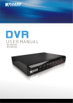
This is an operation guide for BDx-Series user. This guide gives you BDx-Series’s way of configuration of system
program.
If you are first user of BDx-Series DVR, even though you are experienced with similar products like this, we recommend
you to read this manual carefully and follow the instructions inside before using this product.
CAUTION
The copyright of this manual belongs to CNB technology. It is prohibited to copy this manual without permission. We do
not guarantee, if your system is damaged by your mis-using disapproval components or
mis-operation.
If you have any problems or questions with our product, please contact the dealer you bought from or CNB Technology.
If you need to open the system for modification or repairing, it is recommended that you have to
request an engineer’s assistance by contacting the dealer you bought it from or CNB Technology. DSx-Series and
BDx-Series are registered trademarks of CNB Technology DVR system. This product has certification for domestic and
industrial use. Also, it has taken CE for Europe, FCC
for the U.S.
Contents
1
System Requirements......................................................................................................................................6
2
Monitoring Storage Mode ................................................................................................................................. 6
2.1 Checking of Time and Storage Equipment Using Space........................................................................... 9
2.2 Divided Screen Control............................................................................................................................ 9
2.3 Full Screen Function ............................................................................................................................. 10
2.4 Automatic Conversion Button................................................................................................................. 10
2.5 Display of Network Connection Service Status....................................................................................... 11
2.6 Camera Image Input Status View........................................................................................................... 12
2.7 Sensor Detecting Status View................................................................................................................ 12
2.8 Alarm Output Control.............................................................................................................................12
1
Volume Control...................................................................................................................................... 12
2
Search Mode.................................................................................................................................................. 13
3.1 Play of Stored Data ............................................................................................................................... 13
3.1.1 Select Date, Playback Channel and Time .................................................................................... 13
3.1.2 Play of Search Image .................................................................................................................. 14
3.1.3 Panorama play ............................................................................................................................ 17
3.1.4 Motion Search(Quick Play) .......................................................................................................... 18
3.2 Backup Data Search andPlay...............................................................................................................19
3.2.1 Backup Data Search.................................................................................................................... 19
3.2.2 Backup Data Play........................................................................................................................20
3.2.3 Going Out.................................................................................................................................... 21
3.3 Data Backup.......................................................................................................................................... 22
3.3.1 Data Search ................................................................................................................................ 22
3.3.2 Data Play and Backup.................................................................................................................23
2
PAN/TILT Control Mode.................................................................................................................................. 25
4.1 Camera OSD Control ............................................................................................................................ 26
4.2 Pan/Tilt Direction Control.......................................................................................................................26
4.3 Zoom, Focus Control.............................................................................................................................26
4.4 Preset Operation................................................................................................................................... 26
1
Peripheral Equipment Control................................................................................................................ 26
2
Screen Output Function.................................................................................................................................. 27
3
Setup Mode ................................................................................................................................................... 28
6.1 General Information............................................................................................................................... 28
6.2 Camera Movement Setup...................................................................................................................... 30
6.2.1 Camera Movement Setup............................................................................................................ 30
6.2.2 Camera/record Frame Setup ....................................................................................................... 32
6.2.3 Record/Trasmittion Image quality Setup....................................................................................... 34
6.2.4 Input video information on the Recording file................................................................................ 34
6.2.5 Entire Camera Application ........................................................................................................... 35
6.3 Sensor/Alarm Setup .............................................................................................................................. 36
6.3.1 Setting of alarm output and camera preset movement pursuant to sensor input ........................... 36
6.3.2 Wave output................................................................................................................................ 38
6.3.3 E-mail alarm................................................................................................................................ 38
6.4 Audio Setup........................................................................................................................................... 39
6.5 Setup operating schedule......................................................................................................................41
6.6 Network Setup....................................................................................................................................... 43
6.7AdministrateUsers and Recording drive................................................................................................45
6.7.1 Administrate Users ...................................................................................................................... 45
6.7.2 Storage equipment control...........................................................................................................46
6.8 PTZ Control and Image Pursuit Function ............................................................................................... 47
6.8.1 PTZ Connection .......................................................................................................................... 47
6.8.2 Preset Function........................................................................................................................... 47
6.8.3 Speed/angle adjustment .............................................................................................................. 48
2
Use of Network Client..................................................................................................................................... 49
7.1 Checking of Time and Space Used in Storage Equipment......................................................................50
7.2 Divided Screen Control.......................................................................................................................... 50
7.3 Entire Screen Enlargement.................................................................................................................... 51
7.4 Automatic Conversion Button................................................................................................................. 51
7.5 Server List Control................................................................................................................................. 51
7.5.1 Addition of DVR Server................................................................................................................ 51
7.5.2 Cancellation of DVR Server.........................................................................................................54
7.5.3 Modification of DVR Server Information ....................................................................................... 54
7.6 Network Connection.............................................................................................................................. 54
7.7 Cancellation of Network Connection ...................................................................................................... 55
7.8 DVR Auto Connection............................................................................................................................ 55
7.9 Monitoring of Remote Image.................................................................................................................. 55
7.9.1 Configuration of Remote Image Monitoring Screen......................................................................55
7.9.2 Remote Control ........................................................................................................................... 56
7.9.3 Image Channel Entire Screen......................................................................................................56
7.10 Storage of Remote Monitoring Image................................................................................................... 57
7.11 Search of Stored Data.......................................................................................................................... 57
7.12 Remote PTZ Control............................................................................................................................ 58
7.13 Remote Environment Setup................................................................................................................. 58
7.14 Two-way Audio .................................................................................................................................... 59
1
Software Watch-Dog............................................................................................................................ 59
2
Use of Web Client .......................................................................................................................................... 60
8.1 Divided Screen Control.......................................................................................................................... 63
8.2 Automatic Conversion Button................................................................................................................. 63
8.3 Monitoring of Remote Image.................................................................................................................. 64
8.3.1 Configuration of Remote Image Monitoring Screen......................................................................64
8.3.2 Remote Control ........................................................................................................................... 64
8.3.3 Image Channel Entire Screen......................................................................................................64
8.4 Storage of Remote Monitoring Image..................................................................................................... 65
8.5 Remote PTZ Control.............................................................................................................................. 65
8.6 Two-way Audio...................................................................................................................................... 66
Symbols and Letters used in this Manual
Importance mark : Arrangement of items to be considered for completing work
Additional information or tip to avoid in order to completing work
Mouse left button click
Mouse left button double-click
1. System Requirements
Supported OS: (Recommended Windows 2000 or higher) Windows 98SE, Windows 2000, or Windows XP
System Requirements Processor: Intel Pentium III 800MHz or higher Main Memory: 128MB or higher
(Recommended 256MB or higher) Video Card (32MB or higher): ATI Radeon 7000 or higher. (We recommend you to
update driver to the latest version because a old driver may not properly run.) Screen Resolution :
1024 x 768 (16bit or 32bit) DirectX 7.0a or higher
2. Monitoring Storage Mode
Display mode is default mode. It displays real-time images coming from cameras and you can select search, PAN/TILT
control, setup mode.
⑦ ⑧ ⑨ ⑩ ⑪
①
Current date, time, week, and HDD usage space are displayed in percentage.
②
This is used in controlling divided screen.
③
Used for search mode conversion, environment setup, and screen capture. This is used in converting
screen automatically pursuant to entire screen enlargement divided
④
screen.
⑤
Access and connection status of network client is displayed.
⑥
Used for PAN/TILT control.
⑦
Displays camera input status.
⑧
Displays alarm output status.
⑨
Displays sensor input status.
⑩
Adjusts speaker volume.
⑪ Log On / Log Off / Exit Program. It is possible to check current operation status using text and icon which are
displayed on the left/right upper side of screen.
Displayed in red color when recording is under progress.Displayed in green color when recording is not under
progress.This is a name of camera set at environment setup. See environment setup -> camera.
Displays the status under recording together with audio.This is an icon which displays continuous recording
status set in environment setup.Types of icon for each recording status are sensor detection recording
and movement detection recording
When movement is detected, the status of recording the previous action is .
First of all, you have to log in to use the program.
You can use the program by clicking LOG-IN Button after typing User ID and Password.
We recommend you change password after log-in.
(Default registered ID : Administrator , Password : 111)
1) Enlarged viewing of divided screen by one channel Clicking the desired channel with mouse left button enlarges
screen by one channel.
2) Returning to divided screen Clicking mouse left button on screen returns to divided screen.
2.1 Checking of Time and Storage Equipment Using Space
1) Checking of time It is possible to check the time set on current system.
2) Checking of storage equipment using space Displays the capacity used for the entire equipment
installed in the system in percentage. Based on 98% of storage space, the longest data is
automatically cancelled and stored.
2.2 Divided Screen Control
Pressing the screen division button on storage monitoring screen changes the division type seen on the screen. The
selected only one channel is displayed on screen. Each clicking of button changes image channel in regular order
from number 1. Example) 1-> 2 -> 3-> 4…Channel screen is divided into 4 sections, and the 4 channels are
monitored as moving picture. Example) [1,2,3,4], [5,6,7,8] …Channel screen is divided into 6 sections, and the 6
channels are monitored as moving picture. Example) [1,2,3,4,5,6], [7,8,9,10,11,12], [11,12,13,14,15,16] Channel
screen is divided into 8 sections, and the 8 channels are monitored as moving picture. Example) [1,2,3,4,5,6,7,8],
[9,10,11,12,13,14,15,16] Channel screen is divided into 9 sections, and the 9 channels are monitored as moving
picture. Example) [1,2,3,4,5,6,7,8,9], [8,9,10,11,12,13,14,15,16] Channel screen is divided into 10 sections, and
the 10 channels are monitored as moving picture. Example) [1,2,3,4,5,6,7,8,9,10], [7,8,9,10,11,12,13,14,15,16]
Channel screen is divided into 13 sections, and the 13 channels are monitored as moving picture. Example)
[1,2,3,4,5,6,7,8,9,10,11,12,13], [4,5,6,7,8,9,10,11,12,13,14,15,16] Channel screen is divided into 16 sections, and
the 16 channels are monitored as moving picture. Example) [1,2,3,4,5,6,7,8,9,10,11,12,13,14,15,16]
2.3 Full Screen Function
Click this button to display full screen without other functional buttons on the screen.
Double-click the desired image window in order to return to the original status.It you want to view one screen by
enlarging into entire screen, click the left button of mouse after selecting the desired screen in order to enlarge it into
entire screen. In order to return to the original status, double-click the left button of mouse again on the same screen.
When it is enlarged into entire screen with 4 channel divided screen, clicking by selecting other image channel screen
enlarges it into entire screen.
2.4 Automatic Conversion Button
When screen division is set, pressing this button changes camera channel in turns and then outputs monitoring
image.
Press the button again in order to stop automatic conversion function or press image channel screen in order to cancel
automatic conversion function.Automatic conversion time can be set in “Setup mode”-> “Camera/Motion”-> “Channel
Rotate”.
If image channel screen is pressed to come to an end, clicking mouse is not changed into 4 channel division screen.In
case of canceling automatic conversion function by clicking channel, channel is set to be fixed.
2.5 Display of Network Connection Service Status
This displays the network access service status of system and the work status of connecting person if there is user who
have access to the system using client program.
Color of right side lamp displays the status of access service.
It is possible to change access service status by clicking
button.
Yellow color allows access through network client program.White color maintains connection for the person currently
under access, but indicates that it does not provide more network access service.
The number of client
The working status of client
e.g.) Screen display in case that there is one user who have access currently and environment setup is under work.
Double-click the screen which indicates access persons in order to see detailed information of connecting persons.
This is used to end connection compulsively with currently connected users. Select users from list and then click button.
This is used to close detailed view screen.
2.6 Camera Image Input Status View
Displays camera image input status.
Displays the status where camera image is normally inputted.Consists of buttons, and clicking the desired camera button
displays single channel screen.
Displays a status where camera image is not inputted.
2.7 Sensor Detecting Status View
Displays the operation status of each sensor connected to the system. Indicates that sensor is connected and operated
normally. It input occurs on sensor, color changes.
2.8 Alarm Output Control
Displays the operation status of alarm equioment connected to the system, and can control operation by pressing
numerical button.Sets and uses the basic operation status in “environment setup -> DIO”part.
2.9 Volume Control
Can control the volume of audio which is outputted to the outside speaker connected to the system.
3. Search Mode
Click this button on the display mode
3.1 Play of Stored Data
3.1.1 Select Date, Playback Channel and Time
Select the desired month from the calender shown on the screen. The date described in red color
indicates that there is stored data.
Clicking the desired date button displays the stored time for each camera.
If there is no stored image at each time, it is displayed as empty screen.
Selecting and clicking the time band to be regenerated with mouse shows new red color line.
Identification of color on the stored image
▪ Play channel selection
Select the camera channel to be regenerated(CAM 1 ~ CAM 4).
Clicking the button where the camera number to select is displayed with mouse makes selection.
It is possible to select/cancel camera during play.
Yellow
: Displays the continuously recorded image.
Green
: Displays the movement-recorded image.
Blue
: Displays the recorded image when sensor input happens.
Gray
: Displays the case where the recorded image is cancelled by disk over-writing/backup.
3.1.2 Play of Search Image
Moves to start frame. Moves to the last frame.
Moves by one frame into the reverse Moves to play direction by one frame.
direction of play.Regenerates the recorded image of
End of play.
selected channel.
Temporary stop.
Clicking button regenerates image in divided screen suitable for the selected channel.
At this time, time domain changes by minute unit as shown in the figure.
1) Configuration of play screen
①
②
③
Displays the recorded time of regenerated data.
Displays the recorded status such as audio.
Indicates that the data forgery preventing function(digital water marking) is
included.
2) Modification of play timeClick mouse at the desired position in order to regenerate image at
particular time.
3) Play speed adjustment
It is possible to designate play speed of image by clicking
button.
e.g.) x1/10 (Slowest) ~ x32 (Quickest)
4) Audio Play You can playback the recorded voice simultaneously, if the data recorded with
audio.
Audio play is outputted up to a maximum of 8 channels at a time, and clicking and selecting
channel from play screen output only the audio of that channel.
5) Image adjustment
Clicking
button can adjust brightness and contrast of image.
Image adjustment is possible only at the status of temporarily stopping image play by pressing
button.
6) Digital Zoom In/Out
This is a function to enlarge the particular domain of image which is outputted on the screen.
Pressing button and then moving mouse to the upper side of output image change shape of
cursor to
. Clicking mouse at the desired part enlarges image.
This is a function to reduce particular domain of enlarged image. Pressing button and then
moving mouse to the upper side of output image change the shape of cursor to
. Clicking mouse at the desired part of enlarged image reduces image to the original
status.
7) Play of single channel screen Double-click mouse after selecting channel in order to
regenerate it into single screen during selection and play of several channels.
8) Enlargement of entire screen
This is a function which can be used during play only into single channel screen, which
performs a digital zoom function on the entire screen.
3.1.3 Panorama play
This is a function to regenerate image in regular order as time passes at divided mode.
If play is under progress at multi-channel type, select one channel and then change it
into single channel screen.
Press panorama button at regenerated status.
3.1.4 Motion Search(Quick Play)
It is possible to detect only the image where movement occurred by designating
particular position at the image under play.
If play is under progress at multi-channel type, select one channel and then change it
into single channel screen.
Press quick search button at play status.
The initial start part image of selected channel appears in order to set domain. Select thickness
of pen in order to set search domain using the next button.
Designate thickness of pen in order to set search domain on screen (basic thickness).
Designate thickness of pen in order to set search domain on screen(basic thickness
X2).Designate thickness of pen in order to set search domain on screen (basic thickness X4).
Set search domain on screen.
Remove the search domain set on screen partly.
Set entire screen into search domain.
Cancel search domain set on screen totally.
Designate the domain which wants search on screen by dragging mouse.
Start search by pressing
3.2 Backup Data Search and Play
This is a function to search/regenerate the backup data on the external type of hard drive, CD, etc.
3.2.1 Backup Data Search
1) Search drive selection
Select movable HDD, CD-R, CD-RW, etc. which is connected to system.
Select drive and then select date.
2) Selection of date and channel
Select drive and then click and select date.
Red color date indicates that data exists in the selected drive.
White color date is a date set on system.
Select camera channel to search.
The figures are channel-number under date.
The searched data list appears as shown in the followings.
3.2.2 Backup Data Play Select and click the data to regenerate from the searched list.It is possible to select up to
16 data to regenerate.
Regenerate data by pressing
button after finishing data selection.As shown in the below figure, data is regenerated on the divided secreen
suitable for the number of selected data.
1) Information on the data under play Clicking the screen under play displays basic information on start and end
time of data and storage method.
2) Movement of play time Click the data screen to move play time and then click and select the time to move from
the time axis located at the back and lower side using mouse.
3) Movement to backup data search screen
Stop data play and then move to backup data search screen.
3.2.3 Going Out
Pressing
button ends backup data search and play program.
3.3 Data Backup
This is a function to back-up data on the external type hard drive, CD, etc.
3.3.1 Data Search
1) Date selection
If drive is selected, click and select date.
Red color date indicates that there exists data.
2) Time selection
Select time to search data.
The time indicated on the upper side is the time needing search, and the time indicated on the lower side
is the last time.
If time has been set, click
button and then start searching.
▪ Searching the time being set basically displays all the data list recorded on the selected date.
3.3.2 Data Play and Backup
1) Data Play
Select the data on the desired time from the searched data list.
Click
button in case of wanting play.
2) Data backup
▪ Select the data on the backup desired time from the searched data list and then click
button.
Select the drive to back up data.
Clicking
button starts data backup.
3) Option selection
▪ Automatic termination after finishing backup : Backup program is automatically terminated after finishing
backup.
4. PAN/TILT Control Mode
PAN/TILT camera operation can be used when controller such as RX receiver is basically connected. Pressing pan/tilt
control button at monitoring mode shows the following control screen.
Press pan/tilt control button again and then click
button in order to return to monitoring mode.
“Setup -> PTZ”shall be performed in order to control Pan/Tilt, and if there is one or more cameras connected to the
system
Select camera channel to which pan/tilt drive is connected using .
The following functions can be provided according to the kind of camera, Rx receiver, and housing.
Division
Function
Camera function
Zoom In/Out, Focus
Housing function
Light On/Off
Receiver function
PAN(left/right), TILT(up/down), Auto PAN, Auto TILT, Auto PAN/TILT, camera power
source, Preset position
4.1 Camera
OSD
Control
It is possible to
display camera OSD installed inside of Pan/Tilt. It is possible to move and set OSD
menu with direction key for controlling pan/tilt drive control it OSD appears.
4.2 Pan/Tilt Direction Control
moved by clicking the desired direction button in order to adjust up/down/left/right
position of camera connected to Pan/Tilt driver.It is possible to set/cancel auto pan
function using middle button.
Camera can be
Focus Control
It is possible to have zoom in/out and focus adjustment function depending on kinds of
camera connection to Pan/Tilt driver.
4.3 Zoom,
It is possible to adjust zoom and focus of camera by clicking
on.
4.4 Preset Operation
b
u
Preset operation is a function with which user can move to the preset position. User can
t
t
set it arbitrarily at “pan/tilt setup”of “environment setup
mode”. After setting position, uesr
can directly
select the stored position number using
button, and then
directly move by clicking
button at pan/tilt
control mode.
4.5
Periphera
l Equipment Control
Light button can turn on/off the lamp connected to housing. Power button can turn on/off
power inputted to camera. This function is affected by kinds of Rx receiver.
Power On/Off
Light
5. Screen Output Function
This is a button to set so that the image of currently outputted screen may be captured and then
outputted.
Clicking screen
output function
button changes
shape of mouse
cursor to
Putting the
changed mouse
cursor on the
desired image
and then
clicking mouse
show capture
mode screen.
1) Storage on diskette
Supports JPG, BMP format.
Pressing button shows the following
screen.
Designate the
route to store
and the name of
file, set file type,
and then store
it.
2) Captured screen print
If printer is connected to system, the
currently captured screen is printed.
6. Setup Mode
You can configure the system activation.
Setup mode is consisted of 8 tabs. It could be changed by program version. After you select tab, you can setup camera
in detail.
6.1 General Information
1) Site Information
Model Name : It indicates the model name of system.
Product version : It indicates the version of program.
Install Date : It indicates the date of system installed.
Installation place : It is possible to set the place where system will be installed arbitrarily.
Manager : It is possible to input system manager.
2) System Information
System time : You can change the system date & time.
Use Restart(turn off) system : You can setup system restarting(turn off) time
How to use watchdog : Set it so that it may be re-booted during abnormal operation by checking whether
or not to operate system normally at every set time.
Video / HDD loss notification : Beep sound notify for video or HDD loss.
3) Digital Video watermarking
Create and inserted features at frequency domain for each frame in order to detect modulation detection of
MPEG data.
Whether the stored data is modified or not is displayed on the play screen.
4) System Log View
It indicates Aug. 2002.
To choose the date, double-click to
icon.
When you choose the date, it displays major work such as login, search, setup etc. according to the time line on the right
side. If you select time, it displays about the information in detail below the screen.
6.2 Camera Movement Setup
Select the camera channel to set by using
button.
6.2.1 Camera Movement Setup
1) Setting of movement detection domain Designate position by clicking or dragging mouse on the image in order to
check if movement occurs on the camera input image.
Set the entire domain of screen to the movement detecting domain.
Cancel the movement detecting domain designated on the screen.
2) Movement detection sensitivity setup
It is possible to adjust sensitivity by clicking slide bar with mouse.The value set when shipping system is the most proper
sensitivity.
If you need to check of sensitivity, select “Output Motion Area”check box and press “Save”. Then detected movement
area display blue color blocks.
3) Movement detecting event setup
If movement is detected when setting movement detection domain, the set event can be carried out.Beep Out :
Outputs beep sound through system inside speaker. Output the Wave Sound : Outputs default wave sound set at
“I/O setup tap” through outside speaker. Popup to Full screen : Enlarges image into entire screen if movement
occurs at the set camera. Send the Image E-mail : Transmits the captured imaged to the e-mail address set at “I/O
setup tap”. Output Motion Area : Displays an outline of movement area when a movement was detected
at monitoring mode. Notify to network clients : Sets external alarm
connection in order to automatically operate siren, buzzer, etc. to the connected
system in case of having detected movement. (Option)
4) Outside output image setup
It is possible to set the image channel outputted through outside output terminal
separately from the monitor connected to the system. This is set by clicking
button, and in case of selecting one or more channels, output is performed
in regular order according to the time set at
5) Camera name input It is possible to designate the name of camera displayed on the screen at monitoring mode. Input
5 or less Korean letters and 10 or less English letters.
Output the name of set camera on the screen at monitoring mode.
7) Recording resolution setup
It is possible to adjust resolution of recorded image.
Basic value is 320*240, and 640*240 has excellent image quality but low storage speed. In case of having changed
resolution, movement detection domain shall be set again.
It is possible to adjust quality of image recorded according to the site situation.
6.2.2 Camera/record Frame Setup
It is possible to check the number of total frame supported by the system and the remaining frame and then allot it
arbitrarily. In designating the number of frame and displayed in a same speed by channel with a maximum speed.(But,
BDS4824, BDS4812 is displayed in a full speed and this can designate the recording and the transmission speed within
a capture frame range.)
It is possible to check camera channel through the figure written in the left
side and then adjust the number of frame per second for each channel using
left/right direction button.
This shows the number of remaining frames which remains after being allotted for entire frame and each channel
supported by the system.Pressing initialization button inputs general average value.
Set up the number of recording frame for the image channel (setting is available
Recording speed:
within capture speed) Set up the number of transmission frame for the image channel channel
(setting is
Transmission speed:
available within capture speed) Display speed: Displaying speed for the image channel
[Reference] Setting Level Value (Image CIF size) In case
of normal motion
Line bandwidth 1Mbps : Setting the overall transmission frame within 30 frame 256Kbps: Setting the overall
transmission frame within 7 frame
In case of minor motion
Line bandwidth 1Mbps : Setting the overall transmission frame within 60 frame 256Kbps: Setting the overall
transmission frame within 15 frame
Network transmission can be delayed in case of lack of operating performance system. In this case, if the transmission
priority makes high, delay in receiving can be reduced. The setting way of transmission speed is to set up the line speed
of the network setting as “NO Limit”and then adjust the number of the transmission frame. Set up the use speed properly
corresponding to the bandwidth in setting the speed. If the setting is over the limit of bandwidth for frame transmission,
image can be delayed or hung.
6.2.3 Record/Trasmittion Image quality Setup
Image quality is set up in the level of Low, Medium, High, Maximum. In setting Low, the
file size is reduced and image quality is low. In setting Maximum, the image quality is
high and file size gets big. In network transmission, the transmission can be higher if the
image quality setting is low.In case of making the image quality high, if network
transmission speed is set up Low which brings the same effect.
6.2.4 Input video information on the Recording file
Recording file is played on the normal media player such as Wiindow Media player, this is used to check the image
information. Image information is recorded in the saving file which enables the image information in playing the Player.
6.2.5 Entire Camera Application
This is a content of setup which is applied to all cameras.
1) Input signal It is possible to select camera input method. The current system supports two kinds of method such as
NTSC and PAL.
2) Channel automatic conversion It is possible to set channel conversion interval on the divided screen at monitoring
mode.
3) Outside output automatic conversion It is possible to set conversion interval of the channel selected at outside output
image.
4) Popup lasting time Set the time when the entire enlarged screen is maintained at monitoring mode when movement
has happened.
5) Setting to current status Applies the currently set content(Display camera name on screen, Inverse, Movement
detecting event, Movement detection sensitivity) to all cameras.
6.3 Sensor/Alarm Setup
6.3.1 Setting of alarm output and camera preset movement pursuant to sensor input It is possible to make setting
so that alarm output and camera may be operated if sensor input is detected when system is composed as shown in the
following figures.
It operation of number 1 sensor is detected, it is possible to operate digital output number 1 for 60 seconds, proceed with
continuous recording regardless of recording method where camera number 1 is currently operated, and then move to
the position where preset position number 1 is set.
Click the
button in number 1 sensor in order to select input channel.
▪ The selected sensor changes to
type.
▪ It is possible to edit text in order to memorize the position of sensor.
NO(Normal Open) and NC(Normal Close) shall be exactly understood and set for normal operation of sensor
Click
button in number 1 digital output in order to select channel.
▪ The selected digital output channel changes to
type.
▪ Set output maintaining time at second unit by using
button.
▪ Click button and continue to press it, then setup time is changed.
▪ Set time at 60 seconds.
If operation is detected at the number 1 sensor named “sensor1”in the content set until now, digital output channel
number 1 named ‘alarm1’is operated for 60 seconds.
If sensor input happens at camera/preset, set number 1 camera to record.
Because number 1 camera was installed at pan/tilt driver, normal operation is performed only by setting preset at
“Setup -> PTZ”tap.
Select preset number set at the right side items.
Now, we finished interworking of external device for detecting operation of number 1 sensor.
6.3.2 Wave output
If movement happens at the movement sensing domain designated at “Camera/Motion”tap, designate WAV file to output
to external speaker. When WAV file has been designated, it is possible to check output by pressing
button.
6.3.3 E-mail alarm If [image e-mail issue] has been selected at “Camera/Motion”tap, e-mail including image is issued to
the designated receiver. If you forgot password for log-in, e-mail including Administrator’s Password is issued to the
designated receiver by pressing password button.
E-mail Server(SMTP) :Type the address of e-mail server(SMTP). e.g.) smtp.mail.yahoo.com(Type 127.0.0.1 into the
E-mail address if you installed SMTP server to your dvr system)
User ID Type the user ID(Account name) of e-mail server if authentication is required
e.g.) master (Don’t type user ID if you installed SMTP server
to your dvr system) Password Type the password of e-mail
server if authentication is required e.g.) ******* (Don’t type
password if you installed SMTP server to your dvr system)
Sender Address : Type the e-mail name of sender. e.g.)
[email protected] Receiver Address: Type the e-mail name
of each recipient, seperating names with a semicolon(;). e.g.)
[email protected]; [email protected] Interval of
sending: Select e-mail sending interval in second unit.
CNB SMTP server software doesn’t work on Wndows95, 98(se) and ME.
6.4 Audio Setup
This is a part set to record image and audio simultaneously. Separate hardware equipment such as sound card, etc. shall
be installed in order to record audio.
1) Selection of audio device used
Select device to be used.
Separate hardware equipment shall be installed in order to use multi-channel audio.
Selection of device shows device list as shown in the following figure.
▪ Select devices to be used by clicking .
It is possible to adjust audio input volume by clicking equipment name.
2) Selection of audio input (Soundcard user)
<Choose between ‘line-In’and ‘Microphone’for the audio source>
▪ It is possible to record image and audio simultaneously by clicking audio input channel button and clicking camera
button connected.
e.g.) Microphone user
<Select Microphone> <Select a camera number> In this case, camera1 image is recorded together
with the audio inputted to channel1 of sound devices.
e.g.) Line-In user (Left channel of stereo line-in is Audio1 and Right channel is Audio2)
<Select Line-In> <Select a camera number> <Reference cable> In this case, camera1 image is
recorded together with the audio inputted to channel1 of sound devices. camera2 image is recorded together
with the audio inputted to channel2 of sound devices.
3) Configuration the settings for Sound Device : In case of using the sound card, the voice communication can be
improved if setting of audio equipment for the Windows’s system is as below.
[Sounds Tab]
Scheme : No sound
[Volume Tab]
Speaker settings / Advanced / Performance
. Hardware acceleration : Full,
[Audio Tab]
. Sample rate conversion quality : Good
Playback volume -Microphone and Line : Mute.
Volume up to max
Recording volume –Select input Microphone or Line in.
Volume control Advanced : Uncheck AC3 SPDIF and PCM SPDIF check box.
6.5 Setup operating schedule
Select recording type at time/date-working date, weekend/holiday per each camera.
1) Setting-up recording type
▪ Click a button on [Setting-up recording type] and drag the camera & time part as you want.
Select this button when you activate surveillance function without recording.
Select this button when you record continuously.
Select this button when you record in case motion is detected in surveillance area.
Select this button when you record in case sensor event is occurred.
Select this button when you want to record from former image in case motion is perceived. It could be go down the
saving speed if you setup this function to multi camera.
This button initialize the recording value. Initial value is specified as continuous recording. Apply to all
camera which is selected channel.
▪ Screen display pursuant to recording mode
Applicable recording mode
Display of icon at monitoring mode
Not recorded
Continuous recording
Movement recording
Movement recording, sensor recording
Movement recording, prior recording
Movement recording, sensor recording, prior recording
2) Setting up special day function
you can use holiday recording if you specify a certain day as holiday.
Select the day you specified as holiday on calendar.
▪ Select
button when you move to the last or next month.
Select the only one cycle among every year/every month/every week/one time.
Add the date you specified as holiday to the right list.
This function deletes the listed holiday each.
This function deletes all the listed holiday.
3) Pre/post recording setup
Pre-recording frame: In case that system is operated by movement/sensor recording, it is
possible to set the time before recording start movement/sensor event occurs.
Post-recording frame: In case that system is operated by movement/sensor recording, it is
possible to set recording lasting time after movement/sensor event happens.
6.6 Network Setup
This is an item to designate basic matters so that system may be connected to network.
1) System network setup
Setup is possible only in case that system is connected to network environment.
Site access code is a very necessary item in case of having access using client program.
Transmission band width limit(Speed Limit): This is a function of limit so that transmission may be executed
within certain band width when transmitting client data at DVR. Applicable bandwidth is
56Kbps/128Kbps/256Kbps/512Kbps/1.544Mbps/2.048Mbps/Ethernet/NoLimit.
Send Priority: High / Normal options available
High: checking on this option decreases streaming delay or cut-out when high rate of CPU occupancy slow down
video streaming thru network, especially thru WAN. It improves streaming capacity but can slow down
recording speed on hard disk. Slow-downed recording may occur especially in a system of low performance
that doesn’t have enough resource to perform streaming and recording at a time.
2) LAN setup
▪ Setup is performed so that outside access may be possible using client program.
3) MODEM/ISDN setup(Modem setup is a function added newly) System shall be furnished with modem in order to
provide access service through modem. However, problem
may occur due to very low speed as compared to the
speed provided during Ethernet communication when
using modem. 4) Network Port setup Using default port
setting is recommandded but you can change the port if it
is necessary.
5) Web Monitoring setup Web monitoring requires installation of web-server software on DVR system. This option
enables users to monitor from a remote place thru web-browser (e.g. Internet Explorer). For technical terms or details,
your Internet Service Provider (ISP) will help you.
▪ Public IP Subscriber
Check on ‘Support Web Viewer’. You can input other port number if default port number of ‘80’is not workable. Contact
your ISP for available ports for web server construction.
▪ Private IP Subscriber
Private IP requires ‘Proxy Setting’ for web monitoring. Insert IP address of IP sharer or router that has public IP address.
In addition, you have to setup Port forwarding or DMZ of each of the IP sharer or router. (Look up their user manual for
details) BestCap DVR uses default port of 80, 7074, 7075, 7076, 7077, 49557, and 49559 for streaming.
You can insert domain name instead of IP address.
6.7 Administrate Users and Recording drive
6.7.1 Administrate Users
1) User right
Manager : Can use all the functions of system.
General user : Can use monitoring mode only.
2) User addition
Input each content of [user information].
Click additional button in order to add it into [user control] list.
3) User cancel
Select user to be cancelled from the registered [user control] list.
Click cancel button in order to cancel it from [user control] list.
6.7.2 Storage equipment control This is a function to check and control the information on disk installed at system.
The information on disk installed at system is displayed as shown in the figure.
1) Disk recording sequence change
It is possible to designate the recording sequence for the disk installed at system and minimum allowable space.
If disk space is deficient during image recording, cancel and record the oldest data.
6.8 PTZ Control and Image Pursuit Function
6.8.1 PTZ Connection
▪ Select the camera channel to which pan/tilt driver is connected using the upper
button.
Select kind of PTZ from [PTZ model] item.
Select connection port, PTZ speed and RX address.
▪ Click .
When connection is normal, zoom and focus button is activated.
It is possible to select pan swing and tilt swing function.
6.8.2 Preset Function
Preset function can be performed only in case of being supported by pan/tilt driver.
1) Preseting
Move camera to the desired position and then click number with PTZ connected.
A total of up to 10 items can be set, and number button color changes after function is set.
2) Preset position check Set position number from the list as shown in the figure below and then click button for
movement.
3) Preset cancel
▪ In the same way as position checking method, set position number and then click
button.
6.8.3 Speed/angle adjustment
It is possible to set pan speed, tilt speed, zoom speed, and focus speed supported from PTZ.
Move camera to the desired position with PTZ connected.
It is possible to set value by pressing the desired function button.v
Specify the left limits.
Specify the right limits.
Specify the top limits.
Specify the bottom limits.
7. Use of Network Client
Client of CNB DVR can totally operate different DVR server through network access.It is possible to display image of
DVR systems connected to network on the a maximum of up to 36 image channel screen and to use various functions
such as environment setup, control and multi-directional audio communication, etc.
①
②
③
⑤
④
⑥
⑦
1
Displays current date, our, week and HDD usage space set on client system in percentage.
Used for divided screen control.
Used for screen automatic conversion pursuant to entire screen enlargement and divided screen.
Displays the list of server connected to network.
2
3
4
Used for search mode conversion of the server connected to network, environment setup, search mode
5
○
conversion, and screen capture.
6
○ Used for sensor/alarm control and pan/tilt control of the server connected to network.
⑦ Used for remote server access, access cancel, image storage, and camera list view function.
⑧ Displays remote image input status of image channel displays on screen.
⑨ Ends system.
7.1 Checking of Time and Space Used in Storage Equipment
Indicate date/time/week of current client. Recording disk of client is “C drive”, and usage quantity of this disk is displayed.
7.2 Divided Screen Control
Pressing screen division button on the client software monitoring screen changes division type shown on the
screen.Basic usage method is same as DVR system.
Pressing screen division button on monitoring screen changes image type of outputted screen. The channel of client is
outputted as composed in the server list without being limited to any particular DVR.
Remotely monitors the selected one particular channel only.
Remotely monitors 4 channels by dividing channel screen into 4 parts.Example) [1,2,3,4] [5,6,7,8] [9,10,11,12]
[13,14,15,16] …Monitors 6 channels by dividing channel screen into 6 parts.Example) [1,2,3,4,5,6] [7,8,9,10,11,12]
[11,12,13,14,15,16] …Monitors 8 channels by dividing channel screen into 8 parts. Example) [1,2,3,4,5,6,7,8]
[9,10,11,12,13,14,15,16] …Monitors 9 channels by dividing channel screen into 9 parts. Example) [1,2,3,4,5,6,7,8,9]
[8,9,10,11,12,13,14,15,16] …Monitors 16 channels by dividing channel screen into 16 parts. Example)
[1,2,3,4,5,6,7,8,9,10] [7,8,9,10,11,12,13,14,15,16] …Monitors 25 channels by dividing channel screen into 25 parts.
Example) [1,2,…,24,25] [12,13,…,35,36]
Monitors 36 channels by dividing channel screen into 36 parts.
7.3 Entire Screen Enlargement
If you want to see division screen in the entire screen without function button, click button so that it may be
expanded into entire screen.
Double-click mouse in order to return to original status.If you want to see one screen by expanding it into entire screen,
select the desired screen and then double-click the left button of mouse in order to expand it into entire screen.
Double-click the left button of mouse again in order to return to the original status.
7.4 Automatic Conversion Button
Pressing this button with screen division set can output monitoring image by changing camera channel in regular
order.
Click button again in order to stop automatic conversion function.Client cannot adjust automatic conversion time interval
separately, which is set at 5 seconds.
7.5 Server List Control
Used to be connected to the DVR system installed at remote place.
7.5.1 Addition of DVR Server
Select network access type. Direct access type is a general Ethernet environment, which includes LAN, xDSL
and cable network. Dial access type supports access using modem.
▪ If setup has been completed, click
button and add it to list.
DVR servers registered on client are outputted on the list of the following servers.
Use Direct
Access
This is used when the internet address(IP) of connected DVR is known and the address
is authorized address and does not change dynamically. Dynamic address of ADSL, etc.
is possible by operating separate server.
Use Dial Access
If modem is installed at connected DVR and phone line is connected, make access by
inputting the phone number at address input column
Server name
Input name in order to identify server. This server name is replaced with the
name
inputted at the installation place of DVR automatically when being connected to DVR
server.
Server
description
Site code
Input more detailed information on server.
Input access code which was set to server by manager. If this access code is different
from the access code of the server to be connected, access is rejected.
(Default is 100-001)
Server IP
address
This is an item where internet address of server is inputted. In case of selection through
direct connection, input IP address or domain name; and in case of selection through
phone access, input phone number.
User ID
This is an item where user ID registered on server is inputted. If there does not exist user
ID inputted on the server for connection, access is rejected.
User password
This is an item where password for the already inputted user ID is inputted.
Detail Setup
▪ Select ‘Detail Setup’
▪
Auto Display After Connection Displays all cameras immediately when connected
Alert Wave-file Camera input Loss Server will notify the Client of video loss Motion Detection
Server will notify the Client when motion is detected
Use of IP Port forwarding(Recommended to leave as Default)
Connect Port (TCP)
Input the Connecting Port used at the Server
Video Port (TCP)
Input the Video Port used at the Server
Media Server (TCP)
Input the Media Server Port used at the Server
Audio Port (TCP: Connect)
Input the Audio Port used at the Server
Audio Port (UDP: Transport1)
Input the Audio 1 Port used at the Server
Audio Port (UDP: Transport2) Input the Audio 2 Port used at the Server
This option enables automatic reconnection when the connection to DVR is cut out. Check Auto
Connection on DVRs where the connection is to be automatically revived.
7.5.2 Cancellation of DVR Server
Click and select the server needing cancellation from registered DVR server list.
▪ Click
button and then cancel it from list.
Click
button in order to cancel the entire list.
7.5.3 Modification of DVR Server Information
Click and select the server needing modification from registered DVR server list.
Modify the content and then click
button in order to finish modification of server information.
7.6 Network Connection
▪ Clicking and selecting the server to be connected from list make change to
status.
Click mouse item again in order to cancel connection item.
Click
button in order to connect selected servers in regular sequence.
7.7 Cancellation of Network Connection
This is used in disconnecting a selected one of connected DVR servers.
This is used in disconnecting all the connected DVR servers.
7.8 DVR Auto Connection
This button maintain connection between DVR and Client software by trying to reconnect when disconnected.
You can enable this function by checking on ‘Auto Connection’in ‘Detail Setup’. Reconnection is applicable only to the
selected DVRs.
7.9 Monitoring of Remote Image
7.9.1 Configuration of Remote Image Monitoring Screen
▪ Select the system to output image on screen with network connected to DVR server.
If multiple connection is set, click the button in order to select system.
button in order to output camera list connected to selected system. Select camera channel to
be displayed on screen from outputted list and then double-click mouse sothat empty place may appear on the divided
screen.
In case of being connected to several servers, 36 screens may be re-configurated while repeating the above
operation.
Double-click the camera indicating that output is under progress on the list in order not to output the image
composed on divided screen so that screen may disappear.
Camera Status
: Normal camera input
: No camera input
: Normal camera input, and outputting on the current screen
It is possible to click and move tap as shown in the figure below in order to check sensor input status of connected
system or control alarm output.
7.9.3 Image Channel Entire Screen Click button in order to expand particular channel into entire screen at the channel
shown on the current divided screen.
7.10 Storage of Remote Monitoring Image
Stores the image being outputted on the current divided screen into the disk as MPEG file. Stored position is
“C:\RecordData”.
7.11 Search of Stored Data
▪ Select the system to search stored data with network connected to DVR server.
Select system by clicking button if multiple connection is set.
Click search button. When dialogue appears, click “yes”.
The same search screen as DVR server appears. Remote search does not support panorama function and
quick search function..
Clicking this button shows a dialogue “will you search remote video?”; clicking “yes”performs remote search, and clicking
“no”searchs the video stored in the client.(Remote search does not support video random search function.)
7.12 Remote PTZ Control
▪ Select the system where PTZ is installed with network connected to DVR server.
Select system by clicking button if multiple connection is set.
▪ Clicking
button shows control screen.
Basic usage method is same as control function of DVR system.
7.13 Remote Environment Setup
▪ Select the system to change environment setup remotely with network connected to DVR server.
Select system by clicking button if multiple connection is set.
It is possible to set geneal operation matters of selected system by clicking
button.
It is impossible to modify network and PTZ items. ( Refer 6. Setup Mode.)
7.14 Two-way Audio
This button enables voice communication between DVR and Web viewer. This function requires configuring
DVR to record Audio. (Refer to 6.4 Audio Setup)
▪ Configuration the settings for Sound Device :In case of using the sound card, the voice communication can be
improved if setting of audio equipment for the Windows’s system is as below. If the audio equipment is SoundMAX,
delete the basic program and driver and install the driver of audio equipment.
[Sounds Tab]
Scheme : No sound
[Volume Tab]
Speaker settings / Advanced / Performance
-. Hardware acceleration : Full
-. Sample rate conversion quality : Good
[Audio Tab]
Playback volume -Microphone and Line : Mute.
Recording volume –
Volume up to max
Select input Microphone or Line in.
Volume control Advanced : Uncheck AC3 SPDIF and PCM SPDIF check box.
7.15 Software Watch-Dog
Client software automatically executes Client watch-dog software when it starts up. Client watch-dog is different from
DVR watch-dog function. DVR watch dog work on hardware and resets entire DVR system when indicated abnormal
system halt, but Client watch-dog just revives only Web viewer software when the software stops abnormally.
▪ Client watch dog setup
Double click on alarm clock icon
in system tray and Adjust time interval.
Watch dog diagnose operation of program at preset interval. When diagnose indicates abnormal operation of program, it
stops program and restart. Click on ‘Stops (‘X’)’and watch dog will stops.
8. Use of Web Client
Web Client of CNB DVR can totally operate DVR server through web browser. Type IP address or domain name of DVR
server into Address on Web browser(internet explorer) and click “GO”. ([e.g.] http://211.000.000.0 or
http://dvrtest.dyndns.org)
If you are using non default port number, then type the address as below: Port 8000: http://211.000.000.0:8000 or
http://dvrtest.dyndns.org:8000)
If this log in window does not appear, Check ‘Network Setup’of DVR and ‘Port forwarding settings’of IP sharer (Router).
Disable firewall of O/S of DVR system to DVR software, DVR Mediaserver, Apatch. Change web server port if your local
ISP blocks port 80.
First of all, you have to log in to use the program. You can use the program by clicking LOG-IN Button after typing User
ID, Password. When you connect DVR for the first time, your client system download and install ActiveX. It may take
several minutes according to your network condition.
(Once Active X installed, the below Monitoring window appears directly from the next time.)
When the above monitoring window does not appear, disable ‘Popup Stopper’in Tools of Internet Explorer.When video
does not appear, Check ‘Port forwarding settings’of IP sharer (Router). Disable firewall of O/S of DVR system to DVR
software, DVR Mediaserver, Apatch, or
It is possible to display image of DVR system connected to network on the maximum of up to 16 image channel screen
and to use various functions such as environment setup, control and multi-directional audio communication, etc.
①
②
③
screen capture.
④
⑤
⑥
⑦
⑧
⑨
⑩
⑪
Displays current date, hour and week set on client system.
Used for divided screen control.
Used for environment setup mode conversion of the server connected to network, image storage and
Used for screen automatic conversion pursuant to divided screen.
Displays the list of server connected to network.
Displays the list of image channel
Used for pan/tilt control of the server connected to network.
Displays remote image input status of image channel displays on screen.
Used for audio communication.
Used for sensor/alarm control of the server connected to network.
Displays remote image input status of image channel displays on screen.
8.1 Divided Screen Control
Pressing screen division button on the web client software monitoring screen changes division type shown on the
screen.Basic usage method is same as DVR system.
Pressing screen division button on monitoring screen changes image type of outputted screen.
Remotely monitors the selected one particular channel only.
Remotely monitors 4 channels by dividing channel screen into 4 parts.e.g.) [1,2,3,4] [5,6,7,8] [9,10,11,12]
[13,14,15,16] …Monitors 6 channels by dividing channel screen into 6 parts.e.g.) [1,2,3,4,5,6] [7,8,9,10,11,12]
[11,12,13,14,15,16] …Monitors 8 channels by dividing channel screen into 8 parts. e.g.) [1,2,3,4,5,6,7,8]
[9,10,11,12,13,14,15,16] …Monitors 9 channels by dividing channel screen into 9 parts. e.g.) [1,2,3,4,5,6,7,8,9]
[8,9,10,11,12,13,14,15,16] …Monitors 16 channels by dividing channel screen into 16 parts. e.g.) [1,2,3,4,5,6,7,8,9,10]
[7,8,9,10,11,12,13,14,15,16] …
8.2 Automatic Conversion Button
Pressing this button with screen division set can output monitoring image by changing camera channel in regular
order.
Click button again in order to stop automatic conversion function.Client cannot adjust automatic conversion time interval
separately, which is set at 5 seconds.
8.3 Monitoring of Remote Image
button in order to output camera list connected to the system. Select camera channel to be
displayed on screen from outputted list and then double-click mouse sothat empty place may appear on the divided
screen.
▪ Double-click the camera indicating that output is under progress on the list in order not to output the image composed
on divided screen so that screen may disappear.
Camera Status
: Normal camera input
: No camera input
: Normal camera input, and outputting on the current screen
8.3.2 Remote Control
You can check sensor input status of connected system or control alarm output.
8.3.3 Image Channel Entire Screen Click button in order to expand particular channel into entire screen at the channel
shown on the current divided screen.
8.4 Storage of Remote Monitoring Image
Stores the image being outputted on the current divided screen into the disk as MPEG file. Stored position is
“C:\RecordData”.
8.5 Remote PTZ Control
▪ Select the system where PTZ is installed with network connected to DVR server.
Select system by clicking button if multiple connection is set.
▪ Clicking
button shows control screen.
Basic usage method is same as control function of DVR system.
8.6 Two-way Audio
This button enables voice communication between DVR and Web viewer. This function requires configuring DVR to
record Audio. (Refer to 6.4 Audio Setup)
▪ Configuration the settings for Sound Device :In case of using the sound card, the voice communication can be
improved if setting of audio equipment for the Windows’s system is as below. If the audio equipment is SoundMAX,
delete the basic program and driver and install the driver of audio equipment.
[Sounds Tab]
Scheme : No sound
[Volume Tab]
Speaker settings / Advanced / Performance
-. Hardware acceleration : Full
-. Sample rate conversion quality : Good
[Audio Tab]
Playback volume -Microphone and Line : Mute.
Recording volume –
Volume up to max
Select input Microphone or Line in.
Volume control Advanced : Uncheck AC3 SPDIF and PCM SPDIF check box.