1
Communication
3.
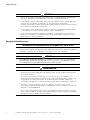
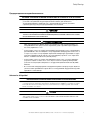
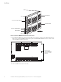
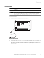
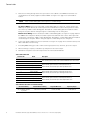
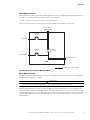
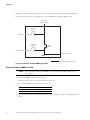
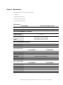
Connect MBM cable wires to the UPS signal input and relay connectors using Table 2. The cable wires
should be connected to the control terminals using the mating connectors supplied with the UPS. Refer to
the communication chapter of the BladeUPS user's guide for UPS terminal locations.
Table 2. MBM to UPS Terminals
From MBM
To UPS
Conductor Color
Bypass Status (Com)
Relay Output Contacts (Com)
Black
Bypass Status (NO)
Relay Output Contacts (NO)
Red
Force to Bypass (-)
Signal Input 1 (-)
White
Force to Bypass (+)
Signal Input 1 (+)
Green
Activate Bypass (-)
Signal Input 2 (-)
Orange
Activate Bypass (+)
Signal Input 2 (+)
Blue
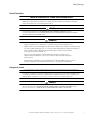
Configure UPS For
UPS Connector
Tightening Torque
On Bypass
Force Bypass
0.5 Nm (4.5 lb in)
Request Bypass
Configuring UPS Signals for Bypass Mode
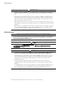
Only one UPS (the UPS connected to the MBM) needs to be configured for the MBM Activate UPS Bypass
Mode Pushbutton and the UPS Bypass Mode Active Indicator to operate properly. The other UPSs in the
parallel system will receive signals through the external CAN.
NOTE
Refer to the operation chapter of the BladeUPS user’s guide for instructions on control
panel operation.
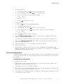
To configure UPS signal input 1, signal input 2, and relay output:
1.
2.
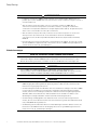
Verify that the UPS firmware is updated to v2.x:
a.
On the control panel of the UPS connected to the MBM, press any button to activate the menu
options, and then press the button until the IDENTIFICATION menu displays.
b.
Press the
c.
If the firmware version is not v2.x, install the firmware from the BladeUPS: Documents, Firmware,
and Installation Video CD or visit www.eaton.com/powerquality to download the latest version and
the instructions for installing it.
button to display the identification data, including the firmware version.
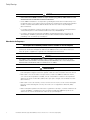
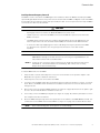
Configure signal input 1:
a.
Press the
button until the Start screen appears.
b.
Select SETTINGS, USER SETTINGS, SIGNAL INPUTS, and Signal.
c.
Select INPUT 1 and press the
d.
Select force bypass and press the
e.
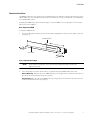
Logic 1 is the default. The following screen text displays:
button to enter the setting mode.
button to save the setting.
Signal: INPUT 1
<force bypass>
Logic: 1
f.
26
Press the
button to save the setting.
Eaton BladeUPS Maintenance Bypass Module (MBM) User’s Guide 164201785—Rev 2 www.eaton.com/powerquality