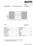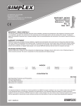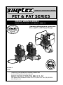
1
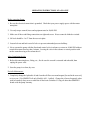
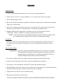
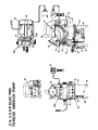
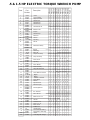
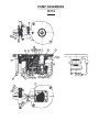
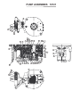
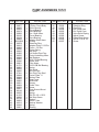
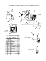
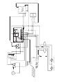
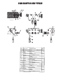
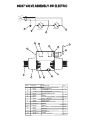
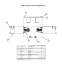
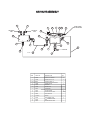
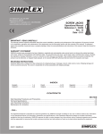
HYDRAULIC & MECHANICAL POWER
PET & PAT SERIES
PRO - MAG
TORQUE
WRENCH SERIES
ELECTRIC & AIR POWER PUMPS
PRIDE
RVIN
SE
H
G
USTRY W
IT
IND
SINCE - 1899
Tem
pl eton
., I
Ke nly & Co
nc
Operating & Maintenance Instructions
For 1/2 and 11/2 H.P. Power Pumps
.
Q U A L IT Y
NT S
E R VI C E A S S
OC
I
EQ U
ER S O F T
O OLS & EQ UIP
MEN
T
A
U IL D
A
AD
US
Part Sheet #:
Revised:
ION
REB
I
AT
E
PM
MEMBER
The world's most complete line of industrial, hydraulic and
mechanical lifting and positioning equipment.
SIMPLEX DIVISION OF TEMPLETON, KENLY & CO., INC.
2525 Gardner Road Broadview, Illinois 60155 (708) 865-1500 / Fax (708) 865-0894
www.tksimplex.com
CA
N
OPERATING INSTRUCTIONS AT A GLANCE
Before operating Pump:
1. Be sure the electrical connection is grounded. Check that your power supply agrees with the motor
nameplate.
2. Use only torque wrench, hoses and equipment rated at 10,000 PSI.
3. Make sure all hose and fitting connections are tight and secure. Hoses cannot be kinked or twisted.
4. Oil level should be 1 to 2” from the reservoir plate.
5. Lossen lock nut and back out relief valve to prevent unintended pressure build-up.
6. Never operate the pump with the directional control valve in advance or retract at 10,000 PSI without
wrench movement for more than 1 minute. Leaving the valve in the advance or retract position with
out the wrench moving will overheat the oil.
After Completing the job:
1. Before disconnecting hoses, fitting, etc., first be sure the wrench is retracted and unloaded, than
unplug the power cord.
2. Store the pump in a clean, dry area.
Periodic Maintenance :
1. Completely change the hydraulic oil and clean the oil filter screen and magnet [located in the reservoir]
twice a year. [Use SIMPLEX oil only, Model # AO1, 1 gallon]. Change the oil more frequently when
used in extremely dusty areas or when the oil has been overheated. Using oil other than SIMPLEX
brand voids the pump warranty.
SAFETY
Working Pressure:
The pump’s maximum working pressure is 10,000 PSI [700 kg/cm ]. Make sure that all hydraulic
equipment such as wrench, hoses, etc. used with this pump are rated at 10,000 PSI operating pressure.
Hydraulic Connections:
Never disconnect or connect any hydraulic hoses or fitting without first unloading the wrench, than unplug
the electrical cord of the pump. Double check the gauge to assure pressure has been released.
When making connections with quick disconnect couplings, make sure the couplings are fully engaged.
Threaded connections such as fittings, gauges, etc. must be securely tightened and leak free.
!! CAUTION !!
Loose or improperly threaded fittings can be potentially dangerous if pressurized,
however, severe over tightening can cause premature thread failure. Fittings need to be tightened secure &
leak free. Never hold or stand directly in line with any hydraulic connections while pressurizing. Never
grab, touch or in any way come in contact with a hydraulic pressure leak. Escaping oil can penetrate
the skin and a serious injury can result.
Do not subject the hose to potential hazard such as sharp surfaces, extreme heat or heavy impact.
Do not allow the hose to kink & twist. Inspect each hose for wear before it is used.
Electrical Power:
1. Check for proper electrical supply before connecting.
2. This motor may spark. Do not operate in an explosive atmosphere or in the presence of conductive
liquids.
a. Do not use a power or extension cord that is damaged or has exposed wiring.
b. All single phase motor come equipped with a three prong grounding type plug to fit the
proper grounded type electrical outlet. Do not use a two prong ungrounded extension cord as
the pump’s motor must be grounded.
Jacking Safely
You must know the weight of what you intend to lift and choose a ram with at least 10% more capacity.
The ram should be placed on a solid foundation so that the base of the ram is fully supported. The load
must be centered on the ram, or equally distributed on multiple rams. Off center loading can result in the
ram slipping out and loss of the load.
Never crawl or place any part of your body under any load at any time. Insert blocking or crib being under
the load as you lift. Hydraulic rams are meant for lifting only and should not be used to support the load
for any period of time.
You should obtain and be familiar with the American National Standards Institute rules that apply to
hydraulic rams and jacks (ANSI B30.1).
INSTRUCTIONS BEFORE USE
Read carefully. Most malfunctions in new equipment are the result of improper operation and/or improper setup
assembly.
Preparation: Remove pump from shipping container -- but do not remove any plugs or valves until the unit is ready
to be fully assembled to prevent dirt or foreign matter from contaminating system.
Inspection: Visually inspect all components for shipping damage. If any damage is found, notify carrier immediately.
Electrical Connections:
Compare motor nameplate against power availability to prevent motor burnout or dangerous electrical overloading.
Minimize the length of extension cords and be sure they are of adequate wire size, with grounded connections.
Hydraulic Connections:
Check hydraulic oil level to prevent possible pump burnout. Open the red plastic fill plug located on the reservoir
plate. Oil level should be approximately 2” from top of reservoir plate -- with cylinders retracted and motor off.
Add SIMPLEX oil as necessary. Do not mix different grade of oil.
Loosen lock nut and back out (turn counter-clockwise ) relief valve to prevent unintended pressure buildup.
Make sure all desired gauge, hose and quick coupler connections are tight and secure before operating. The pumps
pressure ports are located just below the control valve.
Hose Connection:
Couple hoses to pump outlet manifold. “A” port is for advancing and “B” port is for retracting the piston in the
torque wrench. Pump are supplied with the specified coupling halves already connected to the pump ports to
prevent incorrect coupling of hoses to wrench.
Couple hoses to torque wrench. When using SIMPLEX pump and torque wrench combination, Series WH hoses
and couplers are designed so that the pump advance port can only be connected to the wrench advance port, and the
pump retract port can only be connected to the wrench retract port.
OPERATION
Pump Operation:
1. Check all system fittings and connections to be sure they are tight and leak free.
2. Check oil level in reservoir. Oil level should be 1” to 2” from the top of the reservoir plate.
3. Be sure that the pump is “OFF”
4. Be sure the electrical connection is grounded. Check that your power agrees with the motor nameplate.
Plug power cord into outlet.
5. Press “ON” on the pump switch to turn power on. Pressing the “ON” activates the electrical circuit,
but does not turn the motor on. The pump motor is activated by the pendant switch.
6. Pendants supplied with the pumps have a momentary switch. Press momentary switch for
“ADVANCE”. Release “ADVANCE” and torque wrench piston will retract.
NOTE: The electrical motor stays running after pump has stopped. Within 15 seconds of your
last command from the pendant, motor will turn off, preventing heat buildup.
Air removal:
When the wrench is first connected to the pump, To ensure smooth and safe operation, remove air
by cycling wrench several times without load. Cycle unit wrench advances and retracts without
hesitation.
Pressure torque setting:
!! WARNING !! Make these adjustments BEFORE putting torque wrench on nut or bolt head.
The pump pressure setting may be above the pressure needed to provide the
required torque for your application. Exceeding required torque will cause
equipment damage and may lead to serious personal injury.
1. See torque wrench instructions for amount of pressure required to produce desired torque.
2. Loosen lock nut and back out relief valve to prevent unintended pressure build-up.
3. Turn pump on. Press and hold the “ADVANCE” switch, and read pressure gauge.
4. While holding the switch, turn relief valve in (clockwise) to increase pressure or out (counter-clokwise)
to decrease maximum pressure. Repeat until correct pressure is obtained.
5. Tighten lock nut on the relief valve to maintain setting.
6. Run pump several times to test this setting.
REFER TO TORQUE WRENCH INSTRUCTIONS FOR WRENCH OPERATING PROCEDURE.
MAINTENANCE
WARNING: THE ELECTRICAL POWER CORD MUST BE DISCONNECTED FROM ELECTRICAL
OUTLETS BEFORE PERFORMING MAINTENANCE OR REPAIR PROCEDURES.
Maintain oil level:
Check hydraulic oil level every 30 hours of operation. Add SIMPLEX oil when necessary. Oil level should be no
more than 2” from top of reservoir plate.
Completely change oil at least twice a year. The following conditions require more frequent oil changes:
a. Rigorous duty, where oil temperature may reach 140 F.
b. High humidity environment and extreme changes in temperature that can result in condensation inside
the reservoir.
c. Dirty or dusty environments that may contaminate the oil.
Clean oil Filter Screen Once a Year
a. Loosen and remove reservoir plate bolts. Lift pump unit off the reservoir, being careful not to damage
the gasket.
b. Unscrew screen from the bottom of pump unit and clean with nonflammable solvent.
c. Blow dry and reassemble.
Keep areas around pump unobstructed to provide good air flow around the motor and pump.
Keep the motor and pump as clean as possible.
Flushing the Pump:
If you suspect your pump has been contaminated or discover sludge or other deposits on internal components, you
should toughly flush the pump.
a. Remove the old oil from the reservoir, than toughly clean the reservoir and refill with a clean,
nonflammable flushing oil.
b. Reassemble the pump and motor to the reservoir.
c. Now run the pump in no pressure for 1 or 2 minutes maximum.
d. Unplug the pump and remove the motor and pump assembly again. Now drain the flushing oil and
reclean the inside of the reservoir. (Make sure flushing fluid is also drained from pump assembly).
Refill the reservoir with SIMPLEX hydraulic oil and reassemble the pump.
SECTION V
TROUBLESHOOTING
If the procedures listed below do not remedy the problem -- the pump will require
service and should be taken to an authorized Simplex service center for repair
Problem
Cause -- Solution
Motor Will Not Start
Be sure power cord is not damaged. Check for
tripped circuit breaker--be sure breaker is of adequate size. Have qualified electrician inspect for
loose or faulty wiring. Have motor checked for
defective motor capacitor. Be sure electrical supply
and extension cords are adequate.
Noisy Operation
1. Air in system.
procedure).
2. Be sure the oil reservoir is filled to normal level.
3. Check all points where air might leak into
system.
Pump Oil is Over Heating
1. Oil viscosity too high. Replace with Simplex #9.
2. Check for high pressure leakage on upper
pressure plate. (Leaking at plug).
3. Oil level is low. Fill reservoir to normal level, or
refit the pump with larger reservoir.
Pump Runs but Will Not Pump Oil
1. Pump is not primed. Run pump a few minutes
tipping from side to side.
2. Check to make sure that externally adjustable
relief valve set properly.
Check internal relief valve.
3. Damaged O-Rings. Take to nearest Simplex
service center for repair.
4. Defective control valve. (Troubleshoot
separately).
47
15
9
2713
3
43
49
R
C1
A
7
41
11
45
40
.5 & 1.5 HP ELECTRIC
TORQUE WRENCH PUMP
A
D
V
A
D
V
38
19
27
1
6
4
24
30
25
8 33
18
X
14
8 35
17
20
10
41
40
42
10
23
2
37
1
2
3
4
5
6
7
8
9
10
11
12
13
14
15
16
17
18
19
20
21
22
23
24
25
26
27
28
29
30
31
33
35
36
37
38
39
40
41
42
43
44
45
46
47
48
49
Part
Number
18135
69159
69284
68722
66012
68231
68608
66014
69264
68000
561604
68551
69496
69285
93943
Y0010260
69074
69076
69727
43384
68672
69353
68571
43166
68963
18718
18852
43364
86095
87492
68957
68376
69371
43407
88363
43362
99921
4100067
CT210
43378
93596
88429
69976
CT211
69529
43370
43369
69972
69365
18970
69236
43365
69234
43366
68964
43355
69018
69479
G7
69526
68607
98250
43408
Description
18135
Switch On/Off
Gage liquid level
Gasket valve
Gasket Motor
Gasket Pump
Gasket Reservoir
Breather Vent
Roll pin
Gasket Pump
Reservoir
Washer
Pipe Plug
Shroud
1
1
1
1
1
1
1
2
1
1
1
1
1
1
1
1
1
2
1
1
1
1
1
1
1
1
1
1
1 1
1 1
1
1
4
1 1
1 1
1
1
1
1
1
1
1
1
1
1
1 1
4
1 1
1 1
1
1
1
1
1
1
1
1
1
1
1
1
1
1
1
1
1
1
1 1
1 1
1
1
1
1
1
1
1
1
1
1
1
1
1
1
1
1
1
1
1
1
1
Manifold Assembly
21
2
1
1
1
1
1
1
1
1
1
1
1
1
2
1
1
1
1
1
1
1
1
1
1
1
1
Spacer
Filler Plug
Elbow 90
Adapter Assembly
1
1
1
1
2
1
1
1
1
1
1
1
1
1
1
1
8
8
8
8
1
1
1
1
1
1
1
1
Valve Assembly
Gauge Bracket Plate
1
1
1
1
1 1
1 1
Screw Manifold & Valve
3
3
3
Pump Assembly
Screw Cover
Pipe Plug
Motor Electric
1
1
1
1
2 2 2
2 2 2
1 1 1
1 1 1
1 1 1
8 8 8
12
1
1
1
1
1
1 1
1 1
1 1
1
1
1
Nipple
Nipple
Tube Elec T-Wrench
Screw Motor
Washer
Pipe Connecto
Female Coupler
MountingBracket
Adv. Pendant
Elbow 90 Strt.
BHCS 10-24X .25
Hex Nut
SCR Self Form
Screw 1/4 - 20
Motor Cover
Rubber Foot
700 Bar Gage
Cover Plate (All Others)
Cover Plate (1 Gal. Only)
Screw
Pres Gauge W / Flange
3
3
3
1 1
1
2 2 2 2
8 8 12 8
1 1 1 1
6 6 6 6
1
1 1 1
1 1
1 1
1 1 1
1
1 1 1 1 1 1
1 1 1 1 1 1
4 4 4 4 4 4
4
2 2
2 2 2
4 4 4 4 4 4
1 1 1 1
1 1 1 1
4 4
4
1
1 1
1 1 1 1
1 1 1 1 1 1
1 1 1
1 1
1 1
2 2
8 8 8
1 1 1
6 6 6
1
1
1
1
4
2
4
1
1
4
1
1
1
1
12
1
1
1
1
1
3
3
2
1
1
2
1
2
2
1
1
3
2
1
1
2 2
8 12
1 1
6 6
1
1
1
1
1
4
2
4
4
1
1
1
1
1
1
4
4
4
4
1
1
1
PAGE
Item
PET2031
PET2042
PET2131
PET2141
PET2841
PET7042
PET7142
PET7342
PET7842
.5 & 1.5 HP ELECTRIC TORQUE WRENCH PUMP
STOP
RUN
3
31
30
10
17
32
A
P
B
22
15 16
@ PENDANT
P
6
A
B
R
BLACK
YELLOW
26 27
B2
A
29
HOSE CONNECTION DIAGRAM
YELLOW
BLACK
1.5 HP AIR TORQUE
WRENCH PUMP
A
B
P
33
4
11
34
14
20
18
21
19
45
9
44
48
13
12
8
37
46
50
1
23
43
38
37
40
23
7
41
5
2
6
28
36
49
51
24
47
35
25
1.5 HP AIR TORQUE WRENCH PUMP
ITEM PART NO. QTY.
1
2
3
4
5
6
7
8
9
10
11
12
13
14
15
16
17
18
19
20
21
22
23
24
25
26
27
28
29
30
31
32
33
34
35
36
37
38
40
41
43
44
18135
18721
69285
66014
68000
43380
68571
43364
88429
43384
68722
43362
68963
43022
43354
Y0010260
561604
69131
43365
68799
41965
69133
69362
93596
18243
43363
43361
18970
43408
69849
69850
69655
69284
69740
43393
69538R
69361
68786
43366
43508
43509
43379
2
1
1
1
1
2
1
12
12
1
1
3
1
1
4
4
2
1
3
1
1
4
2
2
.05
4
4
1
1
1
1
1
1
1
1
1
1
1
2
2
4
1
DISCRIPTION
1 GAL OIL
Pump Asm.
Reservoir
Gasket
Breather Vent
Hex Pipe Plug
Filler Plug
HHCS 1/4-20x5/8
Washer
Manifold Asm. Torque
Valve Gasket Torque
Screw
Adapter Assy.
Valve Air Torque OC
Screw
Lock Washer
Rollpin
Roll Cage
BHCS 10-24x.25
Pendant Air Torq WRE.
Hose
Rubber Foot Mach.
Swivel Nut Elbow
Screw
Anti-Freeze Lube
HHCS 1/4-20x1
Washer
Elbow 1/4 90Deg.
Pres Gauge W / Flange
Hose Barb
Relief Check Valve
Tube
Gage Liquid Level
Filter Block Asm.
Fltr/Lube Asm.
Push Lock Hose
Nylon Tubing
Bracket Valve Mount.
Heavy Hex Nut
Screw 1/4-20x1.5
Screw 10-32x3/8
Tube Filter Torqpump
ITEM PART NO. QTY.
45
46
47
48
49
50
51
43166
43360
66012
68231
68551
69526
88559
1
1
1
1
1
1
DISCRIPTION
Elbow
Gauge BRK. Filter
Gasket-Motor
Gasket
Gasket
Cover Plate
Air Motor
PUMP ASSEMBIES
18718
46
21
35
36
37
38
15
16
43
18
46 14 38 11 12
13
10
1
8 9 34
7
6
25
5
3 4
2
31
21
26
25
27
28
22
24
23
41
17
18 19
20
40
50
49
48
47
45 29 44 18
32
30
33
PUMP ASSEMBIES
18718
ITEM PART NO. QTY.
1
2
3
4
5
6
7
8
9
10
11
12
13
14
15
16
17
18
19
20
21
22
23
24
25
26
27
28
29
30
31
32
33
34
35
36
37
38
40
41
43
44
68835
68360
66033
66474
69082
66106
66108
68829
56020322
68978
68979
68980
68340
68810
93950
68535
66043
90906
66046
68851
91701
68981
68242
68920
97641
68848
68849
68883
68850
68921
68894
68255
68927
69513
68225
81332
68226
85726
89148
68569
66042
68891
1
1
1
2
1
1
1
1
1
1
1
1
1
1
1
1
1
5
1
1
2
1
1
1
2
1
1
2
1
1
2
4
1
1
1
1
1
2
1
1
1
3
DISCRIPTION
Pump Body
Roller Bearing
Thrust Bearing
Race Bearing
Ecc. Shaft Assm.
Thrust Bearing
Race Bearing
Adaptor Shaft Assm.
O-Ring
Retaining Ring
Adaptor Pump .187 Dia.
Piston Pump .187 Dia
Piston Spring
Ball Stop
1/4 Socket Pipe Plug
Piston Unloading Assm.
Ball Retainer
803C-7D Ball Bearing
Intake Seat
Tube Assm.
R102-10B Ball Bearing
Spring
Set Screw
Nut-Hex Jam
Soc Pipe Plug Steel
Center Plate .11
Bottom Plate
Gear Pump
Shaft-Idler
Screen
Guide Tube
Screw
Plate-Screen Mount
Backup Washer
Spring
Roll Pin 1/8 x 15/16
Ball Stop Screw
Gasket
Screw
Return Tube
Spring
Bearing
ITEM PART NO. QTY.
45
46
47
48
49
50
68892
81093
68004
68003
66085
66083
1
2
1
1
1
1
DISCRIPTION
Retaining Ring
PIpe Plug
Ext. Relief Seat
Ext. Relief Cone
Valve Relief Spring
Adjust Screw
PUMP ASSEMBIES
18852
46
21
35
36
37
38
15
16
46
43
18 38
11
14
12
13
10
9 42
1
8
7
6
25
55
5
3 4
2
53
31
26
21 25
27
22
24
23
41
50
49
48
47
17
18 19
20
34
45
33
29 44 18 32
28
30
54
PUMP ASSEMBIES
18852
ITEM PART NO. QTY.
1
2
3
4
5
6
7
8
9
10
11
12
13
14
15
16
17
18
19
20
21
22
23
24
25
26
27
28
29
30
31
32
33
34
35
36
37
38
41
42
43
44
68507
68360
66033
66474
69082
66106
66108
68829
56020322
68978
68945
67868
68340
68810
93950
68535
66043
90906
66046
68851
91701
68981
68242
68920
97641
68848
68849
68883
68850
68921
68894
68255
68927
89148
68225
81332
68226
85726
68569
69513
66042
68891
1
1
1
2
1
1
1
1
2
1
1
1
1
1
1
1
1
5
1
1
2
1
1
1
2
1
1
2
1
1
2
4
1
1
1
1
1
2
1
2
1
3
DISCRIPTION
2 Piston Pump Body
Roller Bearing
Thrust Bearing
Race Bearing
Ecc. Shaft Assm.
Thrust Bearing
Race Bearing
Adaptor Shaft Assm.
O-Ring
Retaining Ring
Adaptor Piston .225 Dia.
Piston .225 Dia
Piston Spring
Ball Stop
1/4 Socket Pipe Plug
Piston Unloading Assm.
Ball Retainer
803C-7D Ball Bearing
Intake Seat
Tube Assm.
R102-10B Ball Bearing
Spring
Set Screw
Nut-Hex Jam
Soc Pipe Plug Steel
Center Plate .11
Bottom Plate
Gear Pump
Shaft-Idler
Screen
Guide Tube
Screw
Plate-Screen Mount
Screw
Spring
Roll Pin 1/8 x 15/16
Ball Stop Screw
Gasket
Return Tube
Backup Washer
Spring
Bearing
ITEM PART NO. QTY.
45
46
47
48
49
50
53
54
55
68892
81093
68004
68003
66085
66083
68502
82892
82687
1
2
1
1
1
1
1
2
2
DISCRIPTION
Retaining Ring
PIpe Plug
Ext. Relief Seat
Ext. Relief Cone
Valve Relief Spring
Adjust Screw
Piston Block Assm.
SHCS 5/16-24 X 2
Screw
PUMP ASSEMBIES 18721
46
21
35
36
37
38
15
16
46
43
18 38
11
14
12
13
10
9 42
1
8
7
6
25
55
5
3 4
2
53
31
26
21 25
27
22
24
23
41
50
49
48
47
17
18 19
20
34
45
33
29 44 18 32
28
30
54
PUMP ASSEMBIES 18721
ITEM PART NO. QTY.
1
2
3
4
5
6
7
8
9
10
11
12
13
14
15
16
17
18
19
20
21
22
23
24
25
26
27
28
29
30
31
32
33
34
35
36
37
38
41
42
43
44
68507
68360
66033
66474
69082
66106
66108
68829
56020322
68978
68915
68830
68340
68810
93950
68535
66043
90906
66046
68851
91701
68981
68242
68920
97641
68848
68849
68883
68850
68921
68894
68255
68927
89148
68225
81332
68226
85726
68569
69513
66042
68891
1
1
1
2
1
1
1
1
2
1
1
1
1
1
1
1
1
5
1
1
2
1
1
1
2
1
1
2
1
1
2
4
1
1
1
1
1
2
1
2
1
3
DISCRIPTION
2 Piston Pump Body
Roller Bearing
Thrust Bearing
Race Bearing
Ecc. Shaft Assm.
Thrust Bearing
Race Bearing
Adaptor Shaft Assm.
O-Ring
Retaining Ring
Adaptor Piston .210 Dia.
Piston .210 Dia
Piston Spring
Ball Stop
1/4 Socket Pipe Plug
Piston Unloading Assm.
Ball Retainer
803C-7D Ball Bearing
Intake Seat
Tube Assm.
R102-10B Ball Bearing
Spring
Set Screw
Nut-Hex Jam
Soc Pipe Plug Steel
Center Plate .11
Bottom Plate
Gear Pump
Shaft-Idler
Screen
Guide Tube
Screw
Plate-Screen Mount
Screw
Spring
Roll Pin 1/8 x 15/16
Ball Stop Screw
Gasket
Return Tube
Backup Washer
Spring
Bearing
ITEM PART NO. QTY.
45
46
47
48
49
50
53
54
55
68892
81093
68004
68003
66085
66083
68832
82892
82687
1
2
1
1
1
1
1
2
2
DISCRIPTION
Retaining Ring
PIpe Plug
Ext. Relief Seat
Ext. Relief Cone
Valve Relief Spring
Adjust Screw
Piston Block Assm.
SHCS 5/16-24 X 2
Screw
2
Assembly #68829
1
Item
1
2
3
Description
Part
No.
68219
66030
68901
Adapter-Shaft
Bearing
Seal
Qty.
1
1
1
3
Assembly #68535
Item
1
2
3
4
4
1
3
2
4
3
1
2
1
2
3
4
3
2
5
12
2
11
6
10
7
14
9
Piston
O-Ring
Back-Up Ring
Roll Pin
Qty.
1
1
1
1
Part
No.
68859
69081
66108
67863
Description
Qty.
Shaft Ecc.
Ecc. Bearing Assembly
Race Bearing
Retaining Ring
1
1
1
1
Assembly #68502 (70 Series)
15
4
16
14
13
Description
Assembly #69082
Item
1
Part
No.
68209
5602010
68145
93837
8
Item Part No.
68502
1
68501
2
90906
3
66042
4
68810
5
66043
6
66046
7
86269
8
68825
9
85727
10
68915
11
68340
12
67868
13
68445
14 5602008
15
93949
16 56080087
Description
Piston Block
Ball St 803C-7D
Spring
Ball Stop
Ball Retainer
Intake Seat
Gasket
Screw
Gasket
Adapter
Spring Piston
Piston (Pump)
Adapter Assembly
O-Ring
SOC Pipe Plug 1/8
Back-Up Ring
Qty.
1
2
1
1
1
1
1
1
1
1
1
1
1
3
1
2
43369 & 43370 MOUNTING BRACKET ASSEMBLY
10
13
B
17
AC
14
AC
TEMPLETON, KENLY
& CO, INC.
13
MIN
13
J
115V JUMPER 1-2 & 3-4
230V JUMPER 2-3
APPLY VOLTAGE TO 1 & 4
17
MOVE "J" WIRE
TO TERMINAL #2
K2
K1
93-01
A
17
93-01
9
-
AC
7
POTTER & BRUMFIELD
T91S5A22-24
N.O. 15A
N.C. 10A
BOTTOM VIEW
240VAC
MEXICO
AC
+
-
6
6
POTTER & BRUMFIELD
T91S5A22-24
N.O. 15A
N.C. 10A
BOTTOM VIEW
240VAC
MEXICO
4
9
3
4
+
8
1
ELEC1 CONNECT J TO 5
ELEC4 & ELEC5 CONNECT J TO 4
MAX
B
A
P
C
O
D E F
N M L
1
2
3
4
5
6
7
8
9
10
K
G
H
I
J
8
9
15
15
14
5
4
6
2
5
15
5
6
BLUE
BROWN
GREEN
2
1
10
9
8
7
15
6
15
16
3
2
1
115V JUMPER 1-2 & 3-4
230V JUMPER 2-3
APPLY VOLTAGE TO 1 & 4
TIGHTEN TO
REMOVE SLACK
DO NOT COMPRESS
HOUSING OF RELAY
TEMPLETON, KENLY
& CO, INC.
4
5
J
ELEC1 CONNECT J TO 5
ELEC4 & ELEC5 CONNECT J TO 4
K2
-
+
-
K1
93-01
POTTER & BRUMFIELD
T91S5A22-24
N.O. 15A
N.C. 10A
BOTTOM VIEW
240VAC
MEXICO
3
93-01
AC
AC
POTTER & BRUMFIELD
T91S5A22-24
N.O. 15A
N.C. 10A
BOTTOM VIEW
240VAC
MEXICO
AC
+
USE 2 SIDED TAPE
AC
11 12
18 19 20
1
43367
DESCRIPTION
MOUNT BRK. TORQ.
1
CIRCUIT BOARD ASM.
RELAY SUB-ASM
RECTIFIER
SCREW
RECTIFIER
HOSE CLAMP
LOCKNUT
FITTING, CORD L-TIGHT
PLUG AND CORD ASSY
HHCS 1/4-20X5/8
HEX NUT
PUSH-ON TERMINAL
BUTT CONNECTOR
WIRE
TIE CABLE
WIRE
TIME DELAY RELAY
RELAY SOCKET
SCREW
WIRE
WIRE
1
1
1
1
2
1
1
2
2
1
2
2
4
2
4
2
1
1
1
2
1
68977
69587
68623
88032
69489
69235
85510
68375
68595
43364
93849
65888
66132
68262
68683
68261
69375
69970
43460
68261B
68262B
USE FOR 43369 ONLY
7
1
43368
2
3
4
5
6
7
8
9
10
11
12
13
14
15
16
17
18
19
20
21
22
43370
1
43369
ITEM PART NO
1
1
1
1
2
1
2
2
2
4
2
4
1
1
1
1
2
1
7
4
8
TIME DELAY
RELAY
3
9
1
USE FOR 43370 ONLY
11
10
+
AC
-
AC
ADVANCE COIL
JUMPER WIRE USE
PART OF 20" BLACK
WIRE PART #69267
-
E.M.
+
RETRACT COIL
GREEN
BROWN
BLUE
A
B
9
BLK
WHT
RED
AC
VALVE CORD
GRN
AC
-
7
+
3
1
115V JUMPER 1-2 & 3-4
230V JUMPER 2-3
APPLY VOLTAGE TO 1 & 4
2
3
TEMPLETON, KENLY
& CO, INC.
4
K1
K2
J
5
6
7
8
9
ELEC1 CONNECT J TO 5
ELEC4 & ELEC5 CONNECT J TO 4
93-01
6
POTTER & BRUMFIELD
T91S5A22-24
N.O. 15A
N.C. 10A
BOTTOM VIEW
240VAC
MEXICO
1
93-01
4
POTTER & BRUMFIELD
T91S5A22-24
N.O. 15A
N.C. 10A
BOTTOM VIEW
240VAC
MEXICO
10
GREEN
WHITE
BLACK
PENDANT
SWITCH
5
6
7
2
1
11
10
4
8
TIME DELAY
3 RELAY 9
JUMPER WIRE
E.M.
AC
GREEN
BLUE
VALVE
BLK
WHT RED
-
GRN
AC
AC
+
BROWN
AC
-
B
9
+
A
7
3
1
115V JUMPER 1-2 & 3-4
230V JUMPER 2-3
APPLY VOLTAGE TO 1 & 4
2
3
TEMPLETON, KENLY
& CO, INC.
4
K1
K2
J
5
6
7
8
9
ELEC1 CONNECT J TO 5
ELEC4 & ELEC5 CONNECT J TO 4
93-01
6
POTTER & BRUMFIELD
T91S5A22-24
N.O. 15A
N.C. 10A
BOTTOM VIEW
240VAC
MEXICO
1
93-01
4
POTTER & BRUMFIELD
T91S5A22-24
N.O. 15A
N.C. 10A
BOTTOM VIEW
240VAC
MEXICO
10
GREEN
RED
WHITE
BLACK
PENDANT
SWITCH
MOVE "J" WIRE
TO TERMINAL #2
43384 MANIFOLD ASM TORQUE
14
2
3
8
9
4
1
11
7
6
5
SECTION A-A
15
A
16
11
R
A
18
60ß REF.
11
17
17
19
13
12
10
ITEM
1
2
3
4
5
6
7
8
9
10
11
12
13
14
15
16
17
18
19
PART NO.
DESCRIPTION
43371
68004
68003
66085
68655
5602012
65881
68695
88508
68999
97641
68918
68917
69372
89698
43380
4100067
CT210
CT211
MANIFOLD TORQ 4 PORT
SEAT
CONE
SPRING REL. VAL.
ADJUST STEM
O'RING
B-U RING
ADJUST WING NUT
ADJUST KNOB
INT. RELIEF ASM. HF
SOC. PIPE PLUG
PIPE COUPLING
PIPE NIPPLE
SCREW
MALE ELBOW
HEX PIPE PLUG
NIPPLE
NIPPLE
FEMALE COUP'R
QTY
1
1
1
1
1
1
1
1
1
1
5
1
1
1
1
6
2
1
1
A
68672 MANIFOLD ASSEMBLY
9
8
7
5
14
6
4
3
2
A
R
11
13
12
10
ITEM
PART NO.
DESCRIPTION
1
QTY
1
68673
MANIFOLD TORQ. WRENCH
1
2
68004
SEAT
1
3
68003
CONE
1
4
66085
SPRING
1
5
68655
ADJUSTING STEM
1
6
5602012
O'RING
1
7
65881
B-U RING
1
8
68695
ADJUSTING WING NUT
1
9
88508
ADJUSTING KNOB
1
10
68999
INT. RELIEF ASM HF
1
11
97641
PIPE PLUG
2
12
68918
PIPE COUPLING
1
13
68917
PIPE NIPPLE
1
14
69372
SCREW
1
69247 VALVE ASSEMBLY 4W ELECTRIC
RED
BLACK
GREEN
WHITE
7
RETRACT COIL
ADVANCE COIL
14
14
3
5
8
6
13
9
2
4
1
16
15
12
ITEM
1
2
3
4
5
6
7
8
9
10
11
12
13
14
15
16
10
PART NO
68710
68130
66132
68375
98250
69373
65887
68388
68389
5603910
68711
68730
85510
68093
56020112
68729
11
DESCRIPTION
VALVE ASSEMBLY
HOLE PLUG
BUTT CONNECTOR
FITTING, CORD L-TIGHT
SCREW
SOLENOID VALVE CORD
SPADE, TERMINAL
COVER, VALVE
GASKET CVR
O'RING
SPRING
COIL 115VAC
LOCKNUT
WIRE NUT
O'RING
PUSHER-SOLENOID
QTY
1
1
1
1
4
1
1
1
1
2
2
2
1
2
4
2
69972 ADVANCE PENDANT
2
1
3
4
A
D
V
A
D
V
5
JUMPER WIRE
SOLDER CONNECTIONS
A2
A2
GREEN
BLACK
WHITE
ITEM
PART NO.
DESCRIPTION
1
69083
PENDANT BODY & RELIEF
1
2
69150
JUNCTION BOX
1
3
69487
SWITCH ON MOMENTARY
1
4
69381
PENDANT CORD 20` LG
1
5
69996
PENDANT LABLE ADV
1
QTY
43022 VALVE AIR TORQUE OC
7
3
4
8
2
1
5
6
ITEM
PART NO.
DESCRIPTION
QTY
1
68725
VALVE ASSY.
1
2
41954
AIR CYL ASSY
2
3
68388
COVER
1
4
68389
GASKET
1
5
68711
SPRING
2
6
56020112
O'RING
4
7
43358
SCREW
4
8
43359
SCREW
8
41950 MOTOR PENDANT AIR ASSEMBLY
4
1
7
2
3
5
6
ITEM
PART NO.
DESCRIPTION
1
41968
BODY-PENDANT
1
2
41969
BLOCK-AIR PENDANT
1
3
41963
CARTRIDGE-AIR
2
4
41964
SWIVEL FITTING
3
5
68808
RETAINING RING
2
6
41970
CARTRIDGE-CAP
2
7
6069613
SAFETY VAL BALL
3
QTY
AIR VALVE ASSEMBLY
12
12
ADVANCE
COIL
RETRACT
COIL
2
14
4
2
10
6
5
1
5
TUBE FROM
FILTER/LUBE
7
P
A
4
1
3
B
1
2
5
1
2
11
8
1
9
MOTOR
13
7" LG
8
ITEM
3
PART NO.
DESCRIPTION
QTY
1
69362
SWIVEL NUT ELBOW
5
2
42380
SWIVEL ADP 1/8 90
2
3
86872
SWIVEL ELBOW 1/4
1
4
42968
SWIVEL TEE 1/8
1
5
42667
REDUCER
3
6
42668
BRANCH TEE
1
7
69547
HOSE BARB
1
8
69361
NYLON TUBING
2
9
43514
AIR VALVE 3W / 2POS
1
10
69852
MALE RUN TEE
1
11
4100067
NIPPLE
1
12
68794
MALE ELBOW TUBE
2
13
68797
MALE CONNECT TUBE
1
14
43515
AIR VALVE 4W / 2POS
1
68790 FILTER / LUBE ASSEMBLY
6
ASSEMBLE WITH LOCTITE 242
4
1
3
2
5
7
ITEM
1
2
3
4
5
6
7
PART NO.
DESCRIPTION
86241
86242
87320
68791
69936
85851
68798
AIR FILTER
AIR LUBRICATOR
PIPE NIPPLE
BRACKET WELD'M
REDUCER
AIR VALVE
HOSE BARB ELBOW
QTY
1
1
1
1
1
1
1
69470 FILTER BLOCK ASSEMBLY
4
5
2
1
3
6
ITEM
PART NO.
DESCRIPTION
1
69546
FILTER BLOCK
1
2
69670
OIL FILTER
1
3
69144
ADAPTER-FILTER
1
4
93950
PIPE PLUG 1/4
2
5
56020112
O'RING
4
6
5602008
O'RING
1
QTY