1
ILUUIII,
I lllllm
I,IllLILll,III
IL
Save This Manual For
Future Reference
A/RS
owners
manual
MODEL NO.
113.239392
SHAPER WITH STEEL
LEGS AND I/2H.P. MOTOR
113.239400
SHAPER WITH STEEL
LEGS AND 3/4 H.P. MOTOR
113.239420
SHAPER
LEGS AND
WITH
STEEL
1 H,P. MOTOR
Serial
Number
Model and serial numbermaybe
on the tront of the table.
You should record
found
both model and
serial numberin a safe place for future
use,
FOR YOUR
SAFETY:
Read ALL
INSTRUCTIONS
carefully.
/I:RRFTSMRN
WOOD SHA
• assembly
• operating
, repair parts
Sears, Roebuck and Co., Hoffman Estates, IL. 60179 U.S.A.
Part No. SP5427
Printed in U.S,A.
ii'_
......
FULL ONE YEAR WARRANTY
I
ON CRAFTSMAN
ii
I IF I
WOOD SHAPER
If within one year from the date of purchase, this Craftsman Wood Shaper Saw fails due to a
defect in material or workmanship, Sears will repair it, free of charge.
WARRANTY SERVICE IS AVAILABLE BY SIMPLY CONTACTING THE NEAREST SEARS SERVICE
CENTER/DEPARTMENT THROUGHOUT THE UNITED STATES.
This warranty applies only while thEs product is used in the United States.
This warranty gives you specific legal rights, and you may also have other rights which vary from
state to state.
Sears, Roebuck and Co., D1817 WA Hoffman Estates, IL. 60179
='-
...............................
.......
IIMrl
.4
GENERAL SAFETY INSTRUCTIONS FOR POWER TOOLS
1. KNOW YOUR POWER TOOL
Read and understand the owner's manual and labels
affixed to lhe tool. Learn its application and limitations
as welt as the specific potential hazards peculiar to
this tool.
2. GROUND ALL TOOLS
This tool is equipped wilh a approved 3-conductor
cord and a 3-prong gounding type plug to fit the proper
grounding type receptacle. The green conductor in the
cord is the grounding wire. Never connect the green
wire to a live terminal.
3. KEEP GUARDS IN PLACE
rn working order, and in proper adjustment and alignment.
4. REMOVE ADJUSTING KEYS AND WRENCHES
Form habit of checking to see that keys and adjusting
wrenches are removed from tool before turning it on.
5. KEEP WORK AREA CLEAN
Ciutlered areas and benches invite accidents. Floor
must not be sfippery due to wax or sawdust.
6. AVOID DANGEROUS ENVIRONMENT
Don't use power tools in damp or wet locations or
expose them to rain. Keep work area well lighted.
Provide adequate surrounding work space.
7. KEEP CHILDREN AWAY
All visitors should be kept a safe distance from work
area.
8, MAKE WORKSHOP CHILD-PROOF
With padlocks, master switches, by removing starter
keys, or storing tools where children can't get them.
9. DON'T FORCE TOOL
It will do the job better and safer at the rate for which it
was designed.
10.USE RIGHT TOOL
Don't force tools or attachment to do a job it was not
designed for.
11.WEAR PROPER APPAREL
Do not wear loose clothing, gJoves, neckties, or jewelry (rings, wrist watches) to get caught in moving
parts. NONSLIP footwear is recommended.
Wear
protective hair covering to contain long hair. Floil long
sleeves above the elbow.
:12.USE SAFETY GOGGLES (HEAD PROTECTION)
Wear safety goggles (must comply with ANSI Z87.1)at
all times, Everyday eyeglasses are not safety glasses.
They only have impact resistant lenses. Also, use
face or dust mask if cutting operation is dusty, and ear
protectors (plugs or muffs) during extended periods of
operation.
13.SECURE WORK
Use clamps or a vise to hold work when practical. It
frees both hands to operate tool.
14,DON'T OVERREACH
Keep proper footing and balance at all times.
15.MAINTAIN TOOLS WITH CARE
Keep tools sharp and clean for best and safest performance. Follow instructions for lubricating and changing accessories.
16.DISCONNECT TOOLS
Before servicing; when changing accessories such as
blades, bits, cutters, etc.
17.AVOtD ACCIDENTAL STARTING
Make sure switch is in "OFF" position before plugging
in.
18.USE RECOMMENDED ACCESSORIES
Consult the owner's manual for recommended accessories. Follow the instructions that accompany the
accessories. The use of improper accessories may
cause hazards.
19.NEVER STAND ON TOOL OR ITS STAND
Serious injury could occur if the tool is tipped or if the
cutting tool is accidentally contacted.
Do not store
materials above or near the tool such that it is necessary to stand on the tool or its stand to reach them.
20.CHECK DAMAGED PARTS
Before further use of the tool, a guard or other part
that is damaged should be carefully checked to ensure
thai it will operate properly and perform its intended
function. Check for alignment of moving parts, binding
or moving parts, breakage of parts, mounting, and any
other conditions that may affect its operation. A guard
or other part that is damaged should be properly
repaired or replaced.
21 .NEVER LEAVE TOOL RUNNING UNATTENDED
Turn power off. Don't leave tool until it comes to a
complete stop,
22.DIRECTION OF FEED
Feed work into a blade or cutter against the direction
of rotation of the blade or cutter only.
Additional Safety Instructions
Safety Signal Words
iDANGER: means if the safety information is not followed
someone will be seriously injured or killed.
WARNING: means if the safety information is not followed someone could be seriously injured or killed.
CAUTION: means if the safety information is not followed
someone might be injured.
CAUTION: Turn motor switch "OFF" and disconnect Power Cord when changing Shaper cutters or
making adjustments.
Safety is a combination of operator common sense and
alertness at all times when the Wood Shaper is being
used.
WARNING: For your own safety, do not attempt to
operate your wood shaper until It is completely
assembled and installed according to the instructions.., and until you have read and understand the
following:
PAGE
1.
2.
3.
4.
5.
General Safety Instructions for Power Tools ............. 2
Getting to Know your Wood Shaper ....................... 12
Basic Wood Shaper Operation ............................... 15
Maintenance ...........................................................
19
Stability of Machine
The Shaper must be bolted securely to a stand or
work bench, in addition, if there is any tendency for the
Shaper to tip over or move during certain operations, it
should be bolted to the floor.
6. Location
The Shaper should be positioned so neither the operator nor a casual observer is forced to stand in line
with the workpiece when straight line shaping. This
Shaper is intended for indoor use only.
7. Protection: Eyes, Hands, Face, Ears, Body
Wear safety goggles that comply with ANSI Z87.1
1968. Wear ear plugs or muffs during extended periods of operation.
Do not wear gloves ... roll long
sleeves above the elbow.
8. Always feed against rotation of the cutter. NEVER
"back up" the workpiece.
9. Do not take deep cuts or feed the stock too rapidly.
10.Be particularly careful in shaping wood that contains
cross grains or knots, as these may cause the hands
to be thrown into the cutter or cause kickbacks.
11 .Before applying power, make sure the keyed washer
is installed immediately under the spindle nut and the
spindle nut is securely fastened, and all guards are in
the proper position. Make sure cutters are sharp.
12.Avoid awkward hand positions, where a sudden siip
could cause a hand to move into the cutter. Never
reach in back of or around the cutter with either hand
to hold down the workpiece.
13.Accumulations of stock or of finished work should not
be allowed on the table. Never clear table while cutter
is rotating.
for Wood Shaper
14.Rubbish, shavings, stock, or other objects or material
should not be allowed on the floor where they may be
a tripping hazard.
15.Use working forms, patterns or ho[ders wherever possible, and keep them maintained, Care should be
taken that the work is securely fastened in these fixtures. Stock is often of such size or shape that it must
be clamped in a holder before being shaped, The
inside jaws which clamp directly against the stock
should be lined with sand paper. Guards may also be
mounted on a holder to afford additional protection.
16.When the fence is used, make sure il is securely fastened and wilt not slip, and is properly adjusted.
17.Do not wear gloves, neckties, loose sleeves, or
ragged or torn clothing of any kind. Wear safety goggles complying with ANSI Z87.1-1968 to protect your
eyes from dust o_'flying particles.
18. DO NOT perform layout, assembly, or set-up work on
the table while the cutting tool is rotating.
19.NEVER perform freehand shaping - Use either the
fence, or a starting pin in the table and a collar on the
spindle, or a pattern.
20.Oo not place your fingers or hands near edge of material being cut.
21 .NEVER perform irregular shaping operations with the
cutter guard removed. Be positive it is installed and
adjusted per instructions.
22.NEVER perform internal shaping operations on this
Shaper.
23.Do not use your hands to remove objects or materials
from around cutters; use a brush.
24.Do not tamper with guards nor make them inoperative
in any way.
25.ALWAYS joint or plane edge on surface of workpiece
that will be in contact with fence and/or table.
26.NEVER attempt to shape warped or twisted or bowed
workpieces.
27.Before leaving the machine, make sure the motor
switch is "OFF" the power cord is disconnected from
the power source, and the cutter has stopped revolving.
28.Never operate the Shaper without a protective cover
on the unused shaft end of a double ended motor.
29.1f any part of this Shaper should break, bend,or fail in
any way or any electrical component fail to perform
properly, or if any is missing, shut off power switch,
remove power supply cord from power supply and
replace damaged missing and/or failed parts before
resuming operation.
WARNING: Do not allow familiarity
(gained from
frequent use of your wood shaper) to become commonplace. Always remember that a careless fraction of a second is surf icient to Inflict severe injury.
30.Note and follow Safety instructions that appear on the
Shaper fence.
MUST ALWAYS
I A KEYED WASHER
WARNING
BE USED UNDER
THE SPINDLE
NUT
/
31.Note and follow Safety tnslructions that appear on the
Shaper Switch asse.mbly.' ......
DANGER
-'OR YOUR OWK SAFETY:
READ ,t_tD
_VJ_L
LIN0 EFI _TM'I00_=_lE
_3E_E
f4 _"
_3PE_TFI_ _HI_JE
_E POSLTNEKE¥_ _ WA_,Ht'FI_£CTLY
LINOE FI 6rt_or-E
T_l
GEFGFIE
pJUT _dD
T_llOi
BPIPIIgLE N_]
F_GEES
f_"
this speed because it could be dangerous,
j
Note and follow safety instructions that appear on the
motor.
&I'+J_-P£
F1121
OF ¢UFI'EI_ |.(r_TO;R,_g _O=T_+FI
FIOTAt
EEl
F.d_M
E_ _ EC_'IOt4
K_P
WARNING: The 4-3/8"flat motor pulley and th-_
2"spindle pulley furnished,
will run the cutterl
approximately 9000 R.P.M. when used with a 34_0 t
motor. Never substitute these pulleys to increase l
FFICU
|I-CAUTION:re+or+
uslng.Reverslble
motor- cheok_
I
RE '#_3+.VPI_
C U31£ _ 'JSE T _'_ Ur{E5 W_{E tt NE_E F-_f
U_ I_Vt_ _+f_AO
13_-'_0
_f_IEN AOJg_,TA_LE
The operation of any power tool can result inforelgn objects being thrown into the eyes, which
can result in severe eye damage, Always wear safety goggles comp_ying with ANSI Z87.1
(shown on Package) before commencing power tool operation.
at Sears retail or catalog steres.
Safety Goggles are available
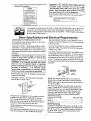
Motor Specifications and Electrical Requirements
CONNECTING TO POWER SOURCE OUTLET
THE GROUNDING PRONG iN ANY MANNER, Use an
This machine must be grounded 'while in use to protect
the operator from electric shock,
adapter as shown and always connect the grounding lug
to known ground,
Plug power cord into a V properly grounded type outlet
protected by a 15 amp dual element time delay or circuit
saver fuse or circuit breaker. If you are not sure that your
outletis properly grounded, have it checked by a qualMed
electrician.
It s recommended that you have a qualified electrician
replace the TWO prong outlet with a properly grounded
THREE prong outlet,
WARNING: Do not permit fingers to touch the terminals of plugs when installing or removing the
plug to or from the outlet.
WARNING: If not properly grounded, this power
tool can incur the potential hazard of electrical
shock. Particularly when used in damp locations in
proximity to plumbing.
If an electrical shock
occurs there is thepotential of a secondary hazard
such as you hands contacting the cutter blade.
If power cord is worn or cut, or damaged in any way, have
It replaced immediately,
Your shaper is wired for 120 volts and has a plug that
looks like the one shown below,
3J_ONO
G_OUNtJ_D
OU1 L_t
_
P_OV?3
PLUO
This power tool is equipped with a 3-conductor cord and
grounding type plug listed by Underwriters' Labotateties. fine ground conductor has a green jacket and is
attached to the tool housing at one end and to the ground
prong in the attachment plug at the other end.
Tihis plug requires a mating 3'conductor grounded type
outlet as shown above.
i
i
If the outlet you are planning to use for this power tool is
of the two prong type, DO NOT REMOVE OR ALTER
A temporary adapter as shown below is available for connecting plugs to 2-prong receptacles. The green grounding lug extending from the adapter must be connected tc
a permanent ground such as to a properly grounded out
let box, The temporary adapter should be used only until
proper_y grounded outlet can be installed by a qualified
electrician.
ADAPTER
NOTE: The adapter illustrated is for use only if you
already have a properly grounded 2-prong receptacle.
NOTE: Make sure the proper extension cord is used and
is in good condition,
The use of any extension cord will cause some loss of
power. To keep this to a minimum and to prevent overheating and motor burn-out, use the table below to determine the minimum wire size (A,W,G,) extension cord,
Use only 3 wire extension cords which have 3-prong
grounding type plugs and 3-pole receptacles which
accept the tools plug,
Extension Cord Length
Wire Size AWG
0-25 FT ........................................................................
16
28-50 FT ...............................................................
.......14
51-100 FT ....................................................................
12
MOTOR ROTATION
The motor is designed to rotate either clockwise or counterclockwise and can be changed from one rotation to the
other by the use of a select switch located on the side of
the motor, Motor must come to full stop before motor
rotation can be reversed,
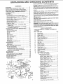
UNPACKING
AND CHECKING
CONTENTS
WARRANTY
.....................................
2
General Safety Instruction for Power Tools ..........
2
Additional Safety Instructions for Wood Shaper ......
3
Motor Specifications and Electrical Requirements ....
4
UNPACKING AND CHECKING CONTENTS .......
5;
List of Loose Parts ..............................
5
ASSEMBLY
......................................
6
Tools Needed ...................................
6
Installing Elevating Rod and Table Support ........
7
Mounting Belt Guard and Motor to Motor Mount .. 7
_nstalling Motor Pulley ...........................
8
Mounting Motor Support Assembly to Shaper .....
9
Mounting Switch Assembly
......................
9
Assembling Steel Legs ..........................
9
Mounting Wood Shaper on Floor Stand ..........
10
Pfugging in Motor ..............................
10
Installing Shaper Fence -- For Straight Edge
Shaping only .................................
11
Installing Shaper Cutter Guard -- For Curved
or Irregular Shaping only .....................
11
GETTING TO KNOW YOUR WOOD SHAPER ....
12
On-Off Switch .................................
12
Elevating Control Lever .........................
13
Spindle Lock Knob ..............................
13
Spindle ........................................
13
Spacers .......................................
13
Keyed Washer .................................
13
Fence Adjusting Knob ..........................
13
Fence Lock Knob ...............................
13
Fence Faces ...................................
t3
Cutter Guard ...................................
13
Starting Pin ....................................
13
Removing and Installing Cutter ..................
13
ADJUSTMENTS
................................
14
Shaper Fence ..................................
!4
Fence Faces ...................................
14
BASIC SHAPING OPERATIONS
.................
15
Use of Cutter Spacers ..........................
15
Straight Edge Shaping ..........................
16
Shaping With Use of Miter Gauge and
Hold-Down Clamp (Optional Accessory) ........
16
Irregular or curved Shaping .....................
17
MAINTENANCE
.................................
19
LUBRICATION
..................................
19
Motor Maintenance and Lubrication
.............
19
RECOMMENDED
ACCESSORIES
...............
19
TROUBLE SHOOTING
...........................
20
REPAIR PARTS .................................
22
Motor Connections
.............................
27
CONTENTS
Mod el 113.239392and t 13.239400 Wood Shapers are shipped
complete in one carton and include steel legs and motor.
Separate all parts from packing materials and check each one
with the illustration and the list of Loose Parts to make certain
all items are accounted
material.
for, before discarding
any packing
_f any parts are missing, do not attempt to assembte the
Shaper, plug in the power cord or turn the swilch on until t_qe
missing parts are obtained and are installed correclly,
Remove the protective oil that is applied to the table lop and
edges of the table. Use any ordinary household type grease
and spot remover.
CAUTION: Never use gasoline,
volatile solvents.
naplha or similar highly
Apply a coat of automobile wax to the table.
Wipe all parts thoroughly with a clean, dry cloth.
WARNING: For your own safety, never connect plug to
power source outlet until allassembly steps are comple re,
and you have read and understand the safety and operational Instructions.
LIST OF LOOSE PARTS
Included with Model No. 113.239392, 113.239400 and
113.239420
Item
A
B
O
D
E
F
G
J
K
L
M
N
O
P
Q
R
S
T
Part Name
Qty,
Motor Mount ......................................................
1
Guard, Pulley .....................................................
1
Pulley, Motor ......................................................
1
Belt, "V" 112x 33 ................................................
1
Support Assembly, R.H .....................................
1
Support, Assembly L.H ....................................... 1
Guard, Cutter .....................................................
1
Nut, Lock ...........................................................
1
Stud, Nut ............................................................
1
Support, Guard ..................................................
1
Bracket, support ................................................
1
Fence Assembly ................................................
1
Plate, Guard ......................................................
1
Switch Box Assembly ........................................ 1
Spindle Assembly ..............................................
t
Base ..................................................................
1
Owner's Manual .................................................
1
Bag Assembly, Loose Parts
Loose Parts Box #508181
Screw Hex Hd. 3!8-16 x 1 ........................ 2
Washer, .380 x !9/64 x 7/64 .................... 2
Bolt, Carriage 5tl 6-18 x 1-1/4 .................. 4
Washer, 2t/64 x 7t8 x 1t8 ........................ 4
Screw, w/Lockwasher, 5t16-18 x 3/4 ....... 3
Washer, 11/32 x 1-1/16 x 1t8 ................... 2
Screw, Hex Hd. 5/16-18 x 1-1/4 ............... 3
Nut, Hex 5116-!8 ...................................... 7
Lockwasher, Int. 5/16 ............................... 3
Washa r, 21f64 x 314 x 1/16 ...................... 5
Loose Parts Bag #508415 ........................ _...1
Starting Pin ..............................................
1
Insert, Table .............................................
1
Wrench .....................................................
I
Wrench, He× "L" 5/32 ............................... 1
Wrench, He× "L" 1/4 ................................. 1
Knob .........................................................
1
Nut, Hex Jam 318-24 ................................ 1
P,anger, Cable ..........................................
1
Screw, Hex Hd. 5f16-18 x 2 ..................... 2
Elevating Rod ...........................................
!
Screw, Soc. Set 5t16-18 x 5/t6 ............... 1
LIST OF LOOSE PARTS
Item
A
B
C
D
E
F
G
H
J
K
L
M
Part Name
'
*
*
*
*
"
Qty.
Leg ................................................................
4
Screw, Truss Hd. 1t4-20 x 5t8 ..................... 28
Nut, Hex 1./4-20 ............................................ 28
Lockwasher, 1/4 External ............................ 28
Channel, Support .......................................... 2
Stiffener ........................................................ 2
Stiffener, Side ............................................... 2
Stitloner, End ................................................ 2
Screw, Pan Hd. Ty A N8 x I/2 ....................... 4
Nut, Hex Hd. 3/8-16 ...................................... 8
Foot, Leveling ............................................... 4
Motor .............................................................
1
HARDWARE FOR MOUNTING TOOL
,
"
*
*
"
Screw, Hex Hd, 5116-18 x 3 ..........................
Lockwasher, 5,/t6 External ...........................
Nut, Hex Jam, 5/16_18 ..................................
Washe{, 11/32 x 11/16 x 1/16 .......................
3
3
3
3
These parts contained in Loose Part bag #508411.
,,,,,
ASSEMBLY
t,=.
TOOLS NEEDED
!!i
7/'16-_NCH WRSNCH
1/2-INCH WRENCH
9t16-1NCH WRENCH
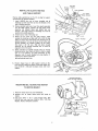
Coal the spindte assembly with cup grease, being sure to
wipe same of the grease intothe elevating slot milled in the
spindle assembly. Use a generous amount of grease to
cover the spindle.
TAPPEO HOLE FOP-,
ELEVATING ROD
SLOT
/
SPINDLEPULLEY
6
JAM NUT
INSTALLING
ELEVATING
AND TABLE
SPINDLE
LOCK
KNOB
ROD
(3/8-24)
TABLE SUPPORT
SUPPORT
SCRE_M
(DOG
Position table upside down on 2 x 4's on edge for support
and clearance for Spindle assembly.
1.
Install
(3/8-24)
jam nut on short
elevating rod and screw the rod into
side of spindle assembly.
2,
Remove spindle lock knob,
Insert the spindle assembly
into the table support,
position
the long angle of the
elevating
rod
straight
down
and tighten
jam nut
securely,
The angle portion
of elevating
rod must be
parallel with spindle assembly.
knob
3.
Install
4.
Rotate
the set screw
into
the table support,
while
moving the elevating
rod back and forth, until the dog
point on end of set screw enters the elevating
slot in
spindle assembly, This can be felt as the set screw and
spindle
assembly are rotated.
Tighten
the set screw,
then back it off
1/4 turn.
This witl allow
enough
clearance
for the spindle
assembly
slot to slide on
dog-point
end of set screw.
5,
Check operation
of spindle
several times, by moving
elevating control
lever back and forth in order to make
sure it is not binding,
yet slides effectively
on the
dog-point
end of screw. Readjust set screw slightly,
if
required, for smooth operation.
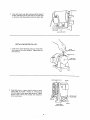
Reinstall
on end of elevating
threaded
end of
the threads in the
spindle
lock
/
KNOB
ELEVATI NG
ROD
2x4
£CREWDR IVER
rod,
"_2
× 4
J
knob.
Position
shaper base on table support
casting so the
three mounting
holes are aligned. Install and tighten the
three 5/16-18
x 3/4-inch
hex-head
screws with
lock
washers.
6,
POSITION MOTOR WITH
5/8 IN. DIA, SHAFT THIS END
BE LT GUARD
MOUNTING
BELT GUARD
AND MOTOR
TO MOTOR MOUNT
1.
2.
Place the motor mount on your workbench.
Support rear of motor mount with 3/4" stock as
shown,
3. Find four 5/16" x 18 x 1-1/4 carriage bolts, four
5/16-18 hex nuts, and two 21/64 x 3/4 x 1/16 Flat
Washers, Position hardware as shown,
MOTOR
3_IN.
STOCK
MOUNT
1/16 IN. THICK
WASHE RS
POINT)
4.
Place Belt Guard under Motor [between Motor Support
Bracket and Motor Mount) and make certain 5/8" shaft
is centered in Belt Guard hole. Install nuts finger tight.
5!16 IN. HEX NUTS
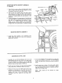
INSTALLING
MOTOR PULLEY
install motor pulley (flat-faced
pulley) on motor shaft,
with closed end of pulley facing out, Tighten pulley set
screw securely.
5_21N,
SETSCREW WRENCH
MOTOR
PULLEY
J
FLUSH
MOTOR
2,
MOUNT
PLATE
Using table insert as a spacer, position motor on motor
mount plate to provide a distance of 1/4-inch from
mounting edge of motor mount plate as shown. Tighten
the four motor mount bolts securely and recheck for
correct positioning,
_IN'-CH
TABLE
IN_ERT
USED AS A SPACER
•8
MOTOR
WITH
SHAFT
MOUNTING MOTOR SUPPORT ASSEMBLY
TO SHAPER
MOTOR
MOTOR
1.
Place V-belt on motor pulley and attach motor mount
plate to shaper base with two bolts 13/8-18 x t-inch}
and washers,
Leave bolts
EL EVATI NG
ROD
finger tight.
2,
Roll the belt onto spindle
pulley,
pull motor
mount
plate toward
end of base until bett is tight enough to
prevent slipping
and tighten
the two bolts, Each bolt
should be in approximately
the same position
in the
base slots.
3.
Position elevating rod in approximate
mid position
and
turn spindle pulley by hand several times to see that the
belt rides in the approximate
mid position
of motor
pulley.
If not,
recheck
assembly. The belt should
change positions on motor pulley as the lever position
is
changed (while the spindle pulley is rotated by hand}.
MOUNTING
I.
Attach
Shaper
PLATE
SPINDLE
PU LL EY
BASE
SWITCH ASSEMBLY
the switch
assembly
table
using the two
packed with
MOUNT
to the underside
of the
screws and lockwashers
/
the switch.
%
I
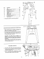
ASSEMBLING
1. Assemble
the
two
(2)
STEEL LEGS
End Stiffeners
and the
two
(2)
Side Stiffeners
using four (4) 1/4-20 Truss head screws.
The End Stiffeners
are placed on top of each Side
Stiffener
as shown.
Insert screws through the 9/32 inch
diameter holes and finger tighten 1/4-20 nuts.
2. Attach
the four (4) legs to the side and End Stiffener
using 1/4-20 screws, lockwashers
and nuts as shown.
3.
Remove the four (4) Truss head screws whict_ were
assembled
in Paragraph
No, One, Place the two (2)
Support
Channels as shown, in position,
align holes in
supports
with
holes
in the side Stiffeners,
replace
Iockwashers
and nuts.
Tighten
all nuts using 7/16"
wrench.
4, The two
of each
screws.
screws,
5.
(2) Stiffeners,
side stiffener
The guard plate
(F} are fastened to the top side
using N8 x t/2 self-threading
is mounted
as shown
using same
Install leveling feet as shown. To level Leg Set, loosen
nut on inside of leg and turn nut on outside to raise or
lower feet. Adjust all four levelers, if necessary, and then
tighten nuts on inside of leg.
NOTE:
These
adjust ment.
levelers
are
not
intended
for
I_eight
item
A
B
C
D
E
F
(3
H
J
K
L
*
*
*
*
*
*
Part Name
Qty.
Leg ................................................................
Screw, Truss Hd. 1/4-20 x 5/8 .....................
Nut, Hex 1/4-20 ............................................
Lockwasher, 1/4 External ............................
Channel, Support ..........................................
Stiffener ........................................................
Stiffenol, Side ...............................................
Stilfener, End ................................................
Screw, Pan Hd. Ty A N8 x lj2 ......................
Nut, Hex Hd, 3/8-16 ......................................
Foot, Leveling ...............................................
4
28
28
28
2
2
2
2
4
8
4
"ii ,'21
* These parts contained in Loose Part bag #508411.
_--L
GUARD
MOUNTING
PLATE
I
WOOD SHAPER ON FLOOR STAND
1. Three mounting holes are provided in the base of the
shaper for the purpose of mounting it securely on a
substantial tool stand with screws or bolts.
2. The tool stand should be high enough so the top surface
of the shaper table will be 35 to 37 inches above the
floor, The shaper must be mounted to allow the motor
to overhang rear edge of toot stand.
NO,
8X
I/2
IN,
pPAHPLIEDHDo SCREW
WITH LEG SET)
CAUTION:
The shaper must be mounted on a
substantial tool stand and secured so there is no
possibility of tipping, The Shaper must be positioned on
the tool stand so that the spindle pulley is guarded from
the bottom,
Place the Shaper on the Steel LEGS, Position as shown,
and align mounting holes. Secure with 3 ea. 5/16" x 18
x 3" screws; washers and nuts,
PLUGGING
IN MOTOR
MOTOR CORD
1. Find plastic cable hanger from among the loose parts.
2. Route the motor cord behind the motor mount, across
the top of the Leg Set and plug it into the receptacle in
the side of the switch box.
3. Bring
the power
cord alongside
the
motor
cord.., wrap the plastic cable hange; around the cords
and attach the hanger to the top of the Leg Set.
CABLE
CORD
10
.
5/16-18
X 2 IN.
HEX HD, SCREWS
AND WASHERS
FENCE
INSTALLING
FOR STRAIGHT
.
SHAPER FENCE EDGE SHAPING ONLY
Install the fence with two 5/16-18 x 2 inch hex head
screws and two plain washers. These screws thread into
tapped holes in the table. Adjust the fence as outlined
on page 13,
_UA_D
INSTALLING
SHAPER CUTTER GUARD FOR CURVED OR IRREGULAR
SHAPING ONLY
NOTE:
1,
I/4-2B LOCKNUT
Fence must be removed,
Assemble
Cutter
Guard
as illustrated.
R.H,
Align the guard support so that it is centered on the shaper
spindle (It may be necessary to loosen the 5/16-18 screws
which secure the support bracket to the channels to
perform this adjustment). After the alignment is achieved
tighten all four screws securely.
SUP_)RT
GUA1_D
Instatl Cutter Guard Assembly to table support using the
two 5/16.t8 x 2 inch hex head screws located at rear of
table support,
5/16-18
X 2
HEX HD. SCRE_,V
11
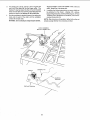
GETTING
TO KNOW
YOUR WOOD
10
CUTTER
SHAPER
GUARD
8
FENCE
LOCK KNOB
9
FENCE
TABLE
MITER
GAUGE
FACE
INSERT
SLOT
TABLE
PIN
FE NCE
ADJUSTING
KNOB
8 FENCE
LOCK KNOB
FENCE FACE
2
ELEVATING
CONI_OL LEVER
SPINDLE
LOCK KNOB
!
ON-OFF
SWITCH
\
MOTOR (NOT
FURNISHED)
MOTOR MOUNT
MOTOR
ROTATION
The motor equipped
with the shaper
is designed
to be
operated in a clockwise or counterclockwise
rotation by use
of a select switch Eocated on the motor, Before the motor is
turned on, move the serect switch
"up"
for clockwise
rotation
or "down"
for counterclockwise
rotation.
The
direction
of rotation
cannot be changed while the motor is
@
running, Turn the motor off and wait until the motor has
stopped completely before selecting
the desired rotation.
WARNING:
always
correct
PLATE
Once
the motor
rotation
KEY
(YELLOW PLASTIC)
has been selected
check to be sure the spindle is rotating
direction
for the cutter being used.
in the
1. ON-OFF SWITCH
CAUTION: Before turning switch on, make sure the cutter
is installed properly and the keyed washer is positioned
below the spindle nut.
The On-Off SwiIch has a locking feature. THIS FEATURE
IS INTENDED TO PREVENT UNAUTHORIZED
AND
POSSIBLE HAZARDOUS
USE 8Y CHILDREI_ AND
OTHERS,
a° TO turn Shaper ON...
insert finger under switch lever
and pull END of lever out.
After turning switch ON, always allow the cutter to
come up to full speed before cutting.
Oo not cycle the motor switch on and off rapidly, as
this may cause the cutter to loosen, in the event this
should ever occur, allow the cutter to come to a
complete stop and retighten the spindle nut normally,
not excessively. Never leave the shaper while the power
is "ON".
b. TO turn shaper OFF...
PUSH lever in. Never leave the
shaper until the cutting tool has come to a complete
stop.
=
KEY
;12
i
C,
2.
Provides added protection for irregular shaping, Guard
is adjustable for various thickness of material,
TO lock switch in OFF position.,,
hold switch IN
with one hand.,.
REMOVE key with other hand.
ALWAYS
LOCK
THE SWITCH "OFF"
WHEN
SHAPER IS NOT IN USE,,.
REMOVE KEY AND
KEEP IT IN A SAFE PLACE.,,
ALSO...
IN THE
EVENT OF A POWER FAILURE
(ALL OF YOUR
LIGHTS GO OUT) TURN SWITCH OFF ... LOCK IT
AND REMOVE THE KEY. THIS WILL PREVENT
THE SHAPER FROM STARTING UP AGAIN WHEN
THE POWER COMES BACK ON.
ELEVATING
CONTROL
CAUTION: A_ways rotate the spindle by hand before
starting the shaper motor to make sure cutter does not
strike guard.
11. STARTING
LEVER
The
Elevating
Control
Lever moves the
spindle
vertically a distance of 7/8-inch
to locate the cutter at
the desired vertical position.
3.
SPINDLE
LOCK KNOB - used to lock the spindle and
quill
assembly
after
the
desired
height
has been
determined.
CAUTION:
Always release the quill lock knob before
attempting
to change the position
of spindle
and
tighten the knob securely before starting operation.
4.
SPINDLE
-- This
maximum
2-1/2-inch
diameter bore.
5.
SPACERS - A total of three spacers are provided, two
7/16 inch thick and one 1/4 inch think for positioning
the cutter for desired shapes.
6.
KEYED
WASHER
Must
always
immediately
below the spindle nut.
7,
FENCE ADJUSTING
moved
forward
or
adjusting knobs.
8.
FENCE
LOCK
shaper
is designed
for use with
diameter cutters having a 1/2-inch
KNOB
CAUTION: Always have the keyed washer directly
under the nut, otherwise the nut may loosen and
serious injury could result,
positioned
KNOB - Each fence face may be
backward
by turning
the fence
-- After
position
has been selected,
the
tightening
the fence lock knobs.
9.
be
PIN
The Starting Pin must be used as a pivot to support the
work until it has been fed into the cutter and against
the collar. The Starting Pin may be located in either of
the two threaded holes near the table insert opening,
depending
upon
the direction of rotatior_, but
ALWAYS on the in-feed side.
12. REMOVING AND INSTALLING
CUTTERS
a. Raise spindle to maximum height
b. To REMOVE cutter, hold spindle with the 1/4" he×
wrench and loosen nut with wrench provided as
shown - Reverse procedure to TIGHTEN SPINDLE
NUT.
NOTE: TO AVOID
POSSIBLE BENDING OF THE
SPINDLE LOOSEN OR TIGHTEN NUTWITH
BOTH
WRENCHES POINTING AS NEARLY IN THE SAME
DI RECTION AS POSSIBLE.
the
desired
fence
fence is secured
face
by
FENCE FACES - Each fence may be moved forward
or backward
by releasing
the fence lock knob
and
turning
the fence adjusting
knobs.
Each fence face
operates independently
of the other, by means of the
adjusting
mechanism.
After the desired fence position
has been selected, it is secured by tightening
the fence
lock
knob.
The fence
faces will
close in from
a
maximum
three-inch
opening
down
to one-inch
for
small diameter
cutters, by _oosening the two screws in
the front of each face and sliding the face to the desired
posiiton.
The screws must be tightened secureiy
after
each setting.
CAUTION: The opening between inner endsof fence faces
should never be larger than required to just clear the
particular cutter being used. ALWAYS ROTATE THE
SPINDLE BY HAND BEFORE STARTING THE SHAPER
MOTOR TO MAKE SURE CUTTER DOES NOT STRIKE
FENCE FACES.
,t
WRONG
10, CUTTER GUARD
NOTE: Used for curved or irregular shaping only fence must be removed and starting pin must be in
place on in-feed side.
RIGHT
13
,!,
ADJUSTMENTS
FENCE FACE
WARNING: For your own safety, turn switch "off" and
removeplugfrom power source outletbeforemaking any
adjustments.
ADJUSTABLE
.
SHAPER FENCE
Move both fence faces out 3/4" by turning the two
fence adjusting knobs,
FENCE
FACE
FENCE
ADJUSTING
KNOBS
STRAIGHT
EDGE
FENCE
2.
Position fence faces in the same plane by using a
framing square or straightedge and adjusting the fence
adjusting
3.
knob.
Loosen the fence attaching
bolts and shift the complete
fence assembly
until
both fence faces are the same
distance from the miter slot.
Tighten fence attaching bolts after fence has been
correctly positioned.
Check this adjustment after tightening bolts to make
sure it did not change,
Lock all controls securely after desired settings have
been completed.
FENCE FACES
1.
Loosen the four (4) screws as shown and slide each
fence face in as close to the cutter as possible, but do
not permit the cutter to strike fence faces,
2. Set the fence faces so the cutter (Not supplied see
Recommended Accessory List] projects far enough
beyond them to produce the desired depth of cut. If
the cutter is set to remove only a portion of the edge of
the work piece, the two fence faces should be set even
with eachother.
14 ¸
FACE
BASIC
SHAPING
OPERATIONS
NOTE: This shaper is designed
for use with maximum
21/2 inch diameter cutters having a 1/2 inch diameter bore.
1. For those operators
who prefer to use a motor
that
rotates clockwise (facing pulley end} which would drive
the spindle
in a clockwise
direction
the motor select
switch
should
be in the
up position.
With
this
combination,
the work would be fed into the cutter from
the left-hand
side of the table. In most cases, the cutter
would have to be turned over.
G%.OCKWIsL:
EDGE
2. For
those
operators
which
may
require
counterclockwise
rotation
of the spindle,
the motor
select switch should be in the down position and with
this combination
the work should be fed into the cutter
from the right side of the shaper.
DI RECTIQ_
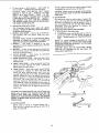
3. Always remember, when mounting the cutter, the
cutting edge of the cutter must lead into the direction of
rotation and the work piece must be fed against the
direction of the cutter.
"_=_
II
FEEDwORK 'F
EDGE
SPfNDI.E
1
USE OF CUTTER
T.he spacers
cutter,
can
be
positioned
SPACERS
below
and
above
the
_
Notice when the spacer is positioned below the cutter
how the spacer provides a bearing surface for the uncut
edge of the board, in addition
to its use as a spacer in
vertical positioning
of the cutter.
/
This same cutter
produce a shape
opposite direction
THE SPINDLE IS
,
.
5,
KEYED
DIRECTION
OF
ROTATI O N
WASHER
TER
"1
2,
SPACER
can be inverted and mounted to
with the board fed through in the
IF DIRECTION OF ROTATION OF
REVERSED,
Notice how the spacer again provides a bearing surface
for the uncut edge of the board.
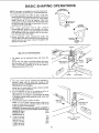
Cut the workpiece to size, so the shaping cut will be as
light aspossible to produce the desired pattern.
CAUTION: Do not attempt to use the Shaper for sizing
a workpiece (except when using the jointer cutter and
adjustable fence).
Feed workpiece against rotation of cutter,
NOTE: it is a very good practice to make a trial cut on
a piece of scrap wood as a double check on the set-up
before using the actual workpiece.
WARNING: Serious injury may result if workpiece is
not always fed into the cutter against the direction of
rotation of the c_
sure,
Experience wile s
d for
producing the srr
If the cut remove
thus
reducing the widt
-feed
fence in front of 4
I face
enough to provide
after
it passesthe cutte
perly
support the work/:
15
SPACER
TABLE
INSERT
DIRECTION
OF FEED
AUXILIARY
FENCEPWORK
SUPPORT
WORKPIECE
STRAIGHT
EDGE SHAPING
CAUTION: The Shaper fence must be used in all straight
edgeshapingoperations.
1. When shaping stock 3 inches wide or less, an auxiliary
fence/work support must be used as shown,
27 IN.
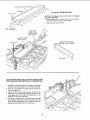
2,
Make the push stick asshown.
SLIGHTLY THICKER
THAN WORKP_ECE
PUSH STICK
(FEEDS UNDER
AUXILIARY _:ENCEi
WORK SUPPORT)
AUXILIARY FENCE,/
WORK
1/8 I N.
MAX.
SUPPORT
SLIGHTLY THINNER AND
NARROWER THAN WORKPIECE
\"x
FENCE
2O
PUSH STICK
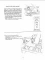
END SHAPING WITH USE OF MITER GAUGE AND
HOLD-DOWN CLAMP (OPTIONAL ACCESSORIES)
1.
NEVER use the Miter Gauge on the Shaper without the
Hold-down
Clamp installed and the workpiece clamped,
2.
Both fence faces MUST
canaot contact them.
3.
Adjust
the head
workpiece
to be
miter gauge slot
angles of the end
4.
Tha board is positioned
in the miter gauge; then hold
the workpiece
firmly against the miter gauge head and
down on the table with your left hand, and feed by
be positioned
so the workpiece
of the miter gauge so the end of the
shaped will be exactly parallel to the
in the table. This holds true for all
of the workpiece.
gripping the lock handle with
your
right hand.
16
IRREGULAR
OR CURVED
(
SHAPING
SPeNDS'AUnT
,
.
A variety of shapes may be produced w_th the shaper by
changing
the the height
of cutter
in relation
to the
workpiece,
by using various combinations
of cutters on
successive passes, and/or
by inverting
cutter and changing
direction of spindle rotation
and feed direction, The table
insert must be removed if the cutter does not clear the hole
in the insert when the cutter is lowered below the table
surface: check clearance before turning switch "ON":
1.
DIRECT
OF
ROTATION
To make irregular
shaping cuts remove power cable
from
electrical
source,
remove
the fence assembly,
select the shaper collar that will position the cutter to
obtain
the desired pattern,
and lock the shaper collar
and cutter on the spindle.
,KEYED
"_
WASHER
DIRECTION
_OF
FEED
SPACER
SHAPER COLLAR
(,OPTIONAL
ACCESSORY)
o
NOTE: A shaper collar may be located above or below
a cutter, or between the two cutters selected,
SHAPERCOLLAR SET
(OPTIONAL ACCESSORY)
2_
Mount
the cutter
guard
Position
the Guard
clear workpiece)
Center
(A)
cutter
guard.
(Guard
should
just
_]_
the Guard over the cutter.
NOTE:
Rotate
clearance inside
STARTING
and adjust as shown.
verticall_
by
(B)
hand and
check for
proper
A
17
PIN
3.
4
The starting pin must be used as a pivot to support the
work until it has been fed into the shaper collar. The
Starting Pin may be located in either of the two threaded
holes near the table insert opening, depending upon the
direction of rotation, but always on the in-feed side.
Workpiece MUST contact the FRONT of the cutter and
collar - toward the miter gauge slot.
5.
Start the workpiece by pivoting it around lhe starting pin
slowty into the path of the culter until the workpiece
contacts the shaper collar,
In addition,11hefollowing operations are some which can
be performed on the shaper - shaping with a pattern,
tongue and groove joints, reading and fluting, etc. ("Power
Tool Know How" Handbooks are available) See Recommended Accessories list.
NOTE: Alter a few hours of operation, tighten both pulley set
screws securely with the Hex wrenches provided.
WARNING: Do not attempt to shape warped lumber.
PIVOT WORKPIECE
AROUND STARTING PiN
COLLAF_
_8
MAINTENANCE
WARNING: For your own safety, turn switch "OFF" and
remove plug from power source outlet beforemaintaining
or lubricating your saw.
NOTE: Alter a few hoursof operation,tightenboth pulleyset
screws securely withthe Hex wrenchesprovided.
Frequently clean your culting toots with Craflsman Gum and
Pitch Remover.
A coat of automobile -type wax applied !o the table will help to
keep the surface clean and allow workp]eces to slide more
freely.
If Lhepower cord is worn or cut, or damaged in any way, have
it replaced immediately.
LUBRICATION
The ball bearings used on the cutter spindle have been
packed with lubricant at the factory and require no further
attention.
To maintain smooth and easy operation, occasionally add a
few drops of oil to the outside of the spindle assembly,
MOTOR
MAINTENANCE
AND LUBRICATION
NOTE: The speed of this motor cannot be regulated or
changed.
1. The sleeve bearings,
in both end shields of the motor,
have
been
lubricated
at the
factory
with
correct
lubricant.
No.
other
part
of the
motor
requires
lubrication.
4,
2. Re-lubricate
motor
bearings
in accordance
with
the
instructions
on the nameplate.
Be sure towipeoff
dirtor
grit if present
around
oil hole caps to prevent
any
possibility
of foreign
materia_
contaminating
the oil
wicks that supply the bearings with oil Use a good grade
of medium
weight
mineral
oil, such as automobile
engine oi!, SAE 20.
NOTE; Motors used on wood-working
tools are
particularly susceptible to the accumulation of sawdust
and wood chips and should be blown out or "vacuumed"
frequently
to prevenI interference
with normal
ventilation and proper operation of the centrifugallyoperated starting switch.
3. If disassembly
of the motor is necessary,
it should be
returned to your nearest Sears retail or mail-order
store
in order to prevent voiding
the guarantee.
SEARS RECOMMENDS
[TEM
Every effort should be made to prevent foreign material
from entering
the motor, When
operated under
conditions likely to permit accumulations of dust, dirt or
waste within the motor, a visual inspection should be
made at frequent intervals. Accumulations of dry dust
can usually be blown out successfully.
THE FOLLOWING ACCESSORIES
CAT. NO,
Casters .......................................................
9-22222,9-22221
Shaper Collar Set ...............................................
See Catalog
Shaper Cutters ...................................................
See Catalog
Push Blocks ................................................................
9-2299
Miter Gauge ..............................................................
9-29929
Miter Gauge Hold Down ............................................ 9-29928
"Power Tool Know How" handbook .......................... 9-29117
Universal Jig ...............................................................
9-3231
Sears may recommend other Accessories not listed in
manual.
See your nearest Sears Store or Catalog Deparlment for
other Accessories,
Do not use any Accessory unless you have recelved and
read complete Instructions for its use.
19
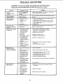
TROUBLE
SHOOTING
WARNING: For your own safety, turn switch "off"
from power source outlet before trouble shooting
TROUBLE
._
and remove plug
your shaper.
REMEDY
PROBABLE CAUSE
...
ii
Spindle
Assembly actuates
too hard.
Set screwengaging slot
in spindle assembly
too tight.
Cuttercomes
100s.
Keyed washer not
properly installed.
The keyed washer must always be used directly
the nut.
1. Work being fed too
rapidly.
2. Insufficient belt
tension.
1. Feed work through more slowly to allow cutter to
remove stock smoothly.
2. Loosen motor mount plate bolts and move motor
slightly toward rear of shaper until belt tension is
correct, tighten bolts.
3. Replace bert.
during operation,
Cutter slow down
during operation.
El
3. Glazed be{t
Binding of Fence
Boardswhen adjusting
in or out.
Shaper produces ragged
or ripple cuts.
Shaper produces a
smooth cut, but does
not hold a straight edge.
Shape Variesacross
width of board.
Bottoms
of fence faces
1. Work piecenot being
held firmly against
fence and/or table.
2. Interrupted feed
past cutter.
3. Dull cutter.
4. Belt slipping - causing
cutter speed to vary.
5. Cutter blades not
concentric. (Blade
segmentshave uneven
lengths.)
6. Work beingfed too
rapidly.
7. Quality of wood not
sufficient to produce
desired results.
J II
I
under
1. Apply sufficient hand pressure in both
directions or revise Auxiliary Fence/Work
Support (pg. 15) accordingly.
2. Maintain continuous feed.
3. Sharpen or replace cutter
4. Adjust belt for proper tension.
5. Replace or resharpen cutter.
6. Feed work through slow enough to produce
smooth cut.
?. Use a better grade of material.
.........
1. Fence faces improperly
set.
2. Spindle Assembly lock
knob not tight.
3. Workpiece not held
snugly against fence.
4. Work piece not held
snugly against table.
5. Work being fed to
rapidly.
6. Attempting to remove
more material than
required to produce
desired shape.
7. Fence loose on table.
I II I I
1. Work not held
securely to miter
gaugeand!or to
table.
2. End of workpieee
not parallel with
miter gaugeslot.
3. End to be shaped
is wavy (not
straight).
,,,11,
I
Loosen the two screws through front of face, raise it
slightly and tighten screws.
striking table.
UL,I,,IIIHII I
i
Tighten screw then back it off 1/4 turn, Adjust until
action is smooth without end play.
i
1. Adjust fence faces.
2. Tighten spindle assembly lock knob.
3. Increase hand pressure or revise Auxiliary
FencetWork Support (pg. 15).
4. Increase hand pressure or revise Auxiliary
Fence/Work Support (pg. 15).
5. Feed work through more slowly.
6. Joint workpiece to proper width before shaping edge.
7. Tighten
fence.
,,,,,,,,,,,,,
H ill
1. Hold work firmly against miter gauge and down
on the table.
2. Adjust miter gauge.
3. Resaw and/or joint as necessary.
=
•20
iii
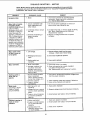
TROUBLE
SHOOTING
-- MOTOR
NOTE: Motors used on wood-working tools are particularly susceptib{e 1othe accumulation
of sawdust and wood chtps and should be blown out or "vacuumed" frequently to prevent
interference with normal motor ventilation.
TROUBLE
Excessive noise.
Motor fails to develop
full power. NOTE:
LOW VOLTAGE: (Power
output of motor
decreases rapidly with
decrease in voltage at
motor terminals. For
example, a reduction of
10% in voltage causes
a reduction of 19% in
maximum power output
of which the motor is
capable, and a reduction
of 20% in voltage causes
a reduction of 36% in
maximum power output.)
PROBABLE CAUSE
REMEDY
1. Motor.
1,
Circuit overloaded with
lights, appliances and
other motors,
2. Undersize wires or circuit
too long.
3.
General overloading
power company
facilities.
1.
Have motor checked by qualified service
technician, Repair service is available at
your nearest Sears store.
1.
Do not use other appliances or motors on
same circuit when using the saw.
2. Increase wire sizes, or reduce length of wiring.
See "Motor Specifications
and Electrical
Requirements" section.
3, Request a voltage check from the power
company.
of
.i
Motor starts slowly
or falls to come up
to full speed.
n
ii
3. Starting switch not
operating.
3,
,
ill
m|
1 Motor overloaded.
i
i
ll,_L
,
' "'
_'
i, i
iii,,,,,
,, ,,,,
,H,,II
i
i
i
2. Have capacitor tested and replace if detective.
3, .Have wiring checked and repaired,
ill.ll.,,,
ii ii ii
'
ii
1 Have switch repJaced and request a voltage check
from the power company.
1. Starting switch not
operating,
2. Voltage too low to permit
motor to reach operating
speed.
3. Fuses or circuit breakers
do not have sufficient
capacity.
'
Have switch _eplaced.
1, Feed work stower into blade.
2 Clean out sawdust to provide normal air
circulation through motor,
See "Maintenance and Lubrication"
section.
1. Burned switch contacts
(due to extended
ho]d-in periods caused
by low line voltage, etc.)
2. Shorted capacitor
3, Loose or broken
connections.
L'"" _"'"_ ""
Frequent opening of
fuses or circuit
breakers,
_Jl_L.iw
2. Have motor repaired or replaced,
l l/i
Motor stalls
(resulting in btown
fuses or tripped
circuit breakers).
i
2. Windings burned out or
open.
2 Improper cooling. (Air
circulation restricted
through motor due to
sawdust, accumulating
inside of saw).
Starting switch in
motor wilt not
operate.
.
1. Request voltage check from the power
company. Check size of circuit wiring,
..................
Motor overheats,
i
1. Low voltage.
.,m
i
i i i
1, Have switch replaced.
2. Request voltage check from the power company.
3. Install proper size fuses or circuit breakers.
""
1. Motor overloaded.
2. Fuses or circuit breakers
do not have sufficient
capacity.
3. Starting switch not
operating (motor does
not reach speed).
1. Feed work slower into blade
2. Install proper size fuse# or circuit
3 Have switch replaced.
21
breakers,
REPAIR PARTS
PARTS LiST FOR CRAFTSMAN
WOOD SHAPER
MODEL
NO. 113.239392,
113.239400
AND 113.239420
1
\
6
40
41
/
42
/
35
33
32
13
22
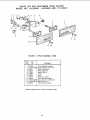
PARTS
LIST FOR CRAFTSMAN
WOOD SHAPER
MODEL
NO. 113.239392,
113.239400
AND
113.239420
Always
Order by Part No. - Not by Key Number
FIGURE 1
Key
No.
Part
No.
Key
No,
Description
Part
No.
Description
,, ,,,
1
2
3
4
5
6
7
8
9
10
t 1
12
13
14
15
16
17
18
19
20
21
22
23
24
25
26
72008
60167
STD 523120
39411
39613
C39290
39512
STD 551037
STD 541137
39629
STD551031
38799
39628
38546
60382
STD 551210
STD 511105
39215
72014
STD 304330
STD 533112
STD 551031
STD 541231
39217
4 53068
27
28
Fence Assembly (See Figure 2)
Washer, .343 x 1.062 x 1/8
"Screw, Hex Hd. 5/16-18 x 2
insert, Table
Pin, Table Dowel
Table (Includes Nameplate)
Knob, Lock
*Washer, 13/32 x 47/64 x 1/!6
*Nut, Hex, Jam, 3/8-24
Stud, Lock
*Washer, 21t64 x 718 x 1/8
Screw, Set, 3/8-24 x 3/4 Dog Pt.
Rod, Elevating
Knob
Switch Box Assembly (See Figure 4)
* Lockwasher, Internal No. 10
*Screw, Pan Hd. 10-32 x 1/2
Base
Spindle Assembly (See Figure 5)
Plate, Guard
*Belt, V, 1/2 x 33
*Bolt, Carriage 5/16-18 x 1-1/4
*Washer 21/64
*Nut, Hex 5/16-18
Mount, Motor
Screw, Mach., 5/16-18 x 3/4,
Hex. Hd. w/Loekwasher
*Standard
Hardware
29
30
31
32
33
34
35
36
37
38
39
40
41
42
43
44
45
46
47
48
-
72003
Guard, Pulley
STD 503102 *Screw, Set 5/16-18 x 5/16,
Soc. Hd. Cup Pt.
39230
Pulley, Motor, (w/Set Screw)
STD 551037 *Washer, 25f64 xl-9/64 x 7/64
STD 523710 *Screw, Hex Hd. 3/8-16 x 1
39216
Support Table
72027
Guard, Asm. Cutter
72024
Support Assembly, R, H.
72025
Support Assembly, L,H.
STD 551231 * Lockwasher, Internat 5/16
STD 523112 Screw, Hex Hd. 5/16 x 18x 1-1/4
72005
Guard, Cutter
60262
Grip
STD 541525 *Nut, Lock 1/4-28
70001
Hub Asrn. Lock
Includes Key INo. 39 )
56634
Stud, Nut
72026
Arm, Guard
72023
Holder, Guard
68036
Hanger, Cable
37435
*Wrench, Hex., 1/4
37837
*Wrench, Hex., 5/32
38713
Wrench
508181
Bag of Loose Parts (Not Illus)
508415
Bag of Loose Parts (Not II/us)
SP5427
Owners Manual (:Not |llus)
Items - May be Purchased
23
Locally.
PARTS
LIST FOR CRAFTSMAN
WOOD SHAPER
MODEL
NO. 113.2393921
113.239400
AND
113.239420
2
!
1
2
4
5
6
9
\
4
6
11
12
11
FIGURE 2 -
Key
No,
1
2
3
4
5
6
7
9
t0
11
t2
10
FENCE ASSEMBLY 72008
Part
No.
Description
72008
Fence Assembly Complete
STD 511005 *Screw, Pan Hd., 10-24 x 1/2
38711
Bracket, Retaining
38612
Knob, Adjusting
18451
Washer, Spring
38413
Frame
38531
Knob
38110
Shoe Assy., Fence
38533
Plate, Work Face (Right)
STD 512507 *Screw, Pan Hd., 1/4-20 x 3/4
STD 551012 *Washer, Plain, t/4
38532
Plate, Work Face (Left)
*Standard Hardware Item - May be Purchased Locally.
• L24
10
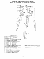
PARTS
LIST FOR CRAFTSMAN
WOOD SHAPER
MODEL
NO. 113.239392,
113.239400
AND
113.239420
r
4
3
1
FIGURE 3 - LEGS
Key
No.
1
2
3
4
5
6
7
8
9
10
11
Part
No.
HARDWARE
-
DescrlptTon
820040
60314
STD541025
STD551225
66060
72030
68059
62615
STD610805
STD541237
803835-1
60841 t
Leg
* Screw, Truss Hd. 1/4-20 x 5/8
*t Nut, Hex 1/4-20
*f Lockwasher, 1/4 External
Channel, Support
Stiffener
Stiffener, Side
Stiffener, End
"I" Screw, Pan Hal. Ty. A N8 x 1/2
*t Nut, Hex Hd. 3/8-16
t Foot, Leveling
Bag of Loose Parts (Not lllus)
FOR MOUNTING TOOL
STD523130
STD551131
STD541231
STD551031
1*t
*t
*
"
Standard Hardware Item - May be purchased locally.
1 These parts contained in Loose Paris Bag #,508411.
Screw, Hex Hd. 5116-18 x 3
Lockwasher, 5/16 External
Nut, HexJam 5!16-18
Washer, 11/32 ID
25
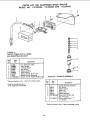
PARTS LIST FOR CRAFTSMAN WOOD SHAPER
MODEL
NO. 113.239392,
113.239400
AND 113.239420
7
8
6
3
/
FIGURE 4 ON/OFF POWER OUTLET 60382
AND MOUNTING
BRACKET
Key
No,
-1
2
3
4
5
6
7
8
Pa_
No.
60382
508984
822206
60256
60374
822205
448007
72034
STD600803
Description
• On/Off Power Outlet
Cord, Molded
Housing, Switch
Key, Switch
Switch, Locking
Cover, Switch
Screw, Pan Hd. No. 6 x 3/4
Bracket. Switch Mounting
"Screw, Pan Hd. Plastite No, B x 3/8
FEGURE 5 - SPINDLE ASSEMBLY
ii,
_Standard Hardware Item - May be Purchased Locally.
,,
Key
No.
• Does Not Include Key No. 3
Order Separately If Required,
!
2
3
4
5
6
,,,
Part
No.
Description
Spindle Assembly Complete
39615
Nut, Spindle
39711
Washer, Keyed
39616
Spacer 1/4
39617
Spacer 7/16
507727
Spindle Assembty
STD 503103 "Screw, Set 5/16-t8 x 3/8,
Soc, Hd, Cup pt,
STD 32801ti "Pulley, (w/Set Screw) "V"
2 x 1/2 Bore
'Standard Hardware Item - May be Purchased Locally.
26
PARTS
LIST FOR CRAFTSMAN
WOOD SHAPER
MODEL
NO. 113.239392,
113.239400
AND 113.239420
FIGURE
6 - MOTOR
PARTS
LIST
ANY ATTEMPT TO REPAIR THIS MOTOR MAY CREATE
A HAZARD UNLESS REPAIR IS DONE BY QUALIFIED
SERVICE TECHNICIAN,
REPAIR SERVICE IS AVAILABLE AT YOUR NEAREST
SEARS STORE
J
3
Key
N o.
Part
N o,
9-12008
820041
820152
60306
4
/
Description
tMotor, 1/2 H.P. (Complete)
Motor, 3/4 H.P. (Complete)
Motor,
1 H.P. (Complete)
Screw, 8-32 x 318, Thread Cutting,
Slotted, Serrated Hd.
64068
64258
Cover, Terminal
Cord with Plug
tStock Item may be secured through the Hardware
Department of Most Sears Retail or Cata!og Order
Houses,
i
ill
....
TERMINAL
MOTOR
GREEN
CONNECTIONS
WARNING:
FOR YOUR
OWN
SAFETY,
NEVER
CONNECT PLUG TO POWER SOURCE OUTLET UNTIL
ALL ASSEMBLY STEPS ARE COMPLETED,
._
INTERNAL\
LOCKWASHER
1. Open motor connector box cover located on left end of
motor (viewed from rear of sawl using a flat blade
screwdriver,
_
/
_
BLACK WIRE TO
TERMINAL T1
2. Remove GREEN SCREW and Iockwasher and insert
screw through round metal terminal on the end of the
GREEN wire of power cord with Iockwasher between
terminal and motor frame, (See illus.)
3. Reinsert GREEN SCREW in the tll.readed hole, Tighten
securely,
EEN WIRE
N SCREW
4. Insert terminal end of WHITE wire on spade terminal
marked T4 on the motor. Push terminal firmly until
seated.
STRAIN RELIEF
i!
_WHITE
5. Insert terminal end of BLACK wire on spade terminal
marked T1 on the motor. Push terminal firmly until
seated.
6. Close motor connector box being sure that power cord is
seated in the largest strain relief groove, and tighten box
cover screws.
27
WIRE TO
L T4
.....
......
lu
i
i i
i.i
i
i
SEAIRS
owners
manual
WOOD SHAPER
SERVICE
Now that you have purchased your wood shaper,
should a need ever exist for repair parts or service,
simply contact any Sears Service Center and most
Sears, Roebuck and Co. stores. Be sure to provide all
pertinent facts when you call or visit.
MODEL NO.
113.239392
The model number of your wood shaper will be found
on a plate attached to your wood shaper on the front
of the table.
SHAPER WITH STEEL
LEGS AND 1/2 H.P.
MOTOR
113.239400
SHAPER WITH STEEL
LEGS AND 3/4 H.P.
MOTOR
113.239420
SHAPER WiTH STEEL
LEGS AND 1 H.P. MOTOR
HOW TO ORDER
REPAIR PARTS
WHEN ORDERING REPAIR PARTS, ALWAYS GIVE
THE FOLLOWING INFORMATION:
PART NUMBER
IF YOU NEED
REPAIR SERVICE
OR PARTS:
MODEL
For Repair Service, Call this
Toll Free Number:
NUMBER
113.239392
113.239400
113.239420
1-800-4-REPAIR
(1.800.473-7247)
PART DESCRIPT!ON
NAME OF ITEM
Wood Shaper
All parts listed may be ordered from any Sears Service
Center and mostSears stores. If the parts you need
are not stocked locally, your orderwill be electronically
transmittedto a Sears Repair Parts Distribution Center
for handling.
For replacement parts informatior_and ordering, call this toll
free number:
1-B00-FON-PART
(1-800-366-7278)
_.,#
Sears, Roebuck and Co., Hoffman Estates, IL. 60179 U.S.A.
Part No. SP5427
Form No. SP5427-3
Printed in U.S.A. 3195