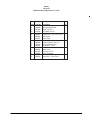
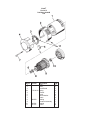
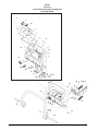
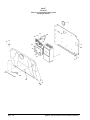
1
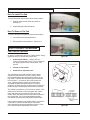
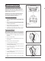
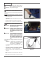
Fusion 27 Battery Burnisher Operator's Manual Patent Pending READ THIS BOOK This book has important information for the use and safe operation of this machine. Failure to read this book prior to operating or attempting any service or maintenance procedure to your Clarke machine could result in injury to you or to other personnel; damage to the machine or to other property could occur as well. You must have training in the operation of this machine before using it. If your operator(s) cannot read English, have this manual explained fully before attempting to operate this machine. Si Ud. o sus operadores no pueden leer el Inglés, se hagan explicar este manual completamente antes de tratar el manejo o servicio de esta máquina. All directions given in this book are as seen from the operator’s position at the rear of the machine. For new books write to: Clarke® , 2100 Highway 265, Springdale, Arkansas 72764. Form No. 70788B 10/04 Clarke® Printed in the U.S.A. Table of Contents Operator Safety Instructions ............................................................................................................................. 3 Introduction & Machine Specifications ............................................................................................................. 5 Procedures For Transporting ........................................................................................................................... 6 Symbols Used On Fusion 27 Machine ............................................................................................................ 7 Machine Control Panel ..................................................................................................................................... 8 How To Prepare The Machine For Operation .................................................................................................. 10 How To Install The Batteries ............................................................................................................. 10 Battery Maintenance ........................................................................................................................... 10 How To Charge The Batteries ........................................................................................................... 11 How To Install The Brushes Or Pad Drivers ..................................................................................... 12 How To Remove The Brushes Or Pad Drivers ................................................................................. 12 How To Operate The Machine ......................................................................................................................... 12 Pad Pressure Operation .................................................................................................................... 12 Pad Pressure Adjustment ................................................................................................................. 13 Operating the Machine ....................................................................................................................... 13 Maintenance ..................................................................................................................................................... 14 Section II Parts and Service Manual How To Correct Problems In The Machine ...................................................................................................... 16 Maintenance, Adjusting Pad Head Limit Switches .......................................................................................... 17 Final Assembly Drawing .................................................................................................................................. 18 Parts List ............................................................................................................................................ 19 Dust Tank Assembly Drawing and Parts List .................................................................................................. 20 Head/MainFrame Asssembly Drawing and Parts List .................................................................................... 21 Main Frame Assembly Drawing ....................................................................................................................... 22 Parts List ............................................................................................................................................ 23 Pad Head Assembly Drawing .......................................................................................................................... 24 Parts List ............................................................................................................................................ 25 Pad Motor .......................................................................................................................................................... 26 Transaxle .......................................................................................................................................................... 27 Control Panel Assembly Drawing .................................................................................................................... 28 Parts List ............................................................................................................................................ 29 Rear Cover Assembly Drawing ........................................................................................................................ 30 Parts List ............................................................................................................................................ 31 Electrical Schematic ......................................................................................................................................... 32 Connection Diagram ........................................................................................................................................ 33 Page -2- Clarke® Operator's Manual -Fusion 27 Battery Burnisher OPERATOR SAFETY INSTRUCTIONS WARNING Clarke® AVERTISSEMENT ADVERTENCIA DANGER: Failure to read and observe all DANGER statements could result in severe bodily injury or death. Read and observe all DANGER statements found in your Owner's Manual and on your machine. WARNING: Failure to read and observe all WARNING statements could result in injury to you or to other personnel; property damage could occur as well. Read and observe all WARNING statements found in your Owner's Manual and on your machine. CAUTION: Failure to read and observe all CAUTION statements could result in damage to the machine or to other property. Read and observe all CAUTION statements found in your Owner's Manual and on your machine. DANGER: Failure to read the Owner's Manual prior to operating or attempting any service or maintenance procedure to your Clarke machine could result in injury to you or to other personnel; damage to the machine or to other property could occur as well. You must have training in the operation of this machine before using it. If your operator(s) cannot read English, have this manual explained fully before attempting to operate this machine. DANGER: Operating a machine that is not completely or fully assembled could result in injury or property damage. Do not operate this machine until it is completely assembled. Inspect the machine carefully before operation. DANGER: Machines can cause an explosion when operated near flammable materials and vapors. Do not use this machine with or near fuels, grain dust, solvents, thinners, or other flammable materials. This machine is not suitable for picking up hazardous dust. DANGER: Lead acid batteries generate gases which can cause an explosion. Keep sparks and flames away from batteries. Do not smoke around the machine. Charge the batteries only in an area with good ventilation. Unplug the AC charger from the wall outlet before operating the machine. DANGER: Working with batteries can be dangerous! Always wear eye protection and protective clothing when working near batteries. Remove all jewelry. Do not put tools or other metal objects across the battery terminals, or the tops of the batteries. DANGER: Using a charger with a damaged power cord could result in an electrocution. Do not use the charger if the power cord is damaged. WARNING: Operating this machine from anywhere other than the back of the machine could result in injury or damage. Operate this machine only from the rear. WARNING: This machine is heavy. Get assistance before attempting to transport or move it. Use two able persons to move the machine on a ramp or incline. Always move slowly. Do not turn the machine on a ramp. If operating machine on a gradient over 2%, do not stop, turn or park. Read the "Procedures For Transporting" in this manual before transporting. WARNING: Machines can topple over if guided over the edges of stairs or loading docks and cause injury or damage. Stop and leave this machine only on a level surface. When you stop the machine, turn the key "OFF". Operator's Manual - Fusion 27 Battery Burnisher -3- Page WARNING: Maintenance and repairs performed by unauthorized personnel could result in damage or injury. Maintenance and repairs must be performed by authorized Clarke personnel only. WARNING: Any alterations or modifications of this machine could result in damage to the machine or injury to the operator or other bystanders. Alterations or modifications not authorized by the manufacturer voids any and all warranties and liabilities. WARNING: Electrical components of this machine can "short-out" if exposed to water or moisture. Keep the electrical components of the machine dry. Wipe the machine down after each use. For storage, keep the machine in a dry building. WARNING: Operating a machine without observing all labels and instructional information could result in injury or damage. Read all machine labels before attempting to operate. Make sure all of the labels and instructional information are attached or fastened to the machine. Get replacement labels and plates from your Clarke distributor. CAUTION: Use of this machine to move other objects or to climb on could result in injury or damage. Do not use this machine as a step or furniture. Do not ride on this machine. CAUTION: Your machine warranty will be voided if anything other than genuine Clarke parts are used on your machine. Always use Clarke parts for replacement. -4- Clarke® Operator's Manual -Fusion 27 Battery Burnisher Introduction & Machine Specifications Introduction & Machine Specifications Clarke’s newly designed Fusion 27 battery burnisher is an efficient and superior floor burnishing machine . The machine uses a pad to burnish a path 27 inches wide. The powder created by burnishing is collected by a dust system. The machine comes complete with six - 6 volt batteries, one on board battery charger, a pad driver and one operator’s manual. SPECIFICATIONS: Clarke® Model Fusion 27 (01264A) Motor, Pad Power Supply Dust Tank Motor Traction Pad Speed Pad Pressure Speed, Forward Speed, Reverse Charger Length Width - Machine Height Buffing Rate Buffing Swath Weight w/Batteries (370Ah) Shipping Weight w/batteries (370Ah) 3 hp 36V 370 Ah 1/2 gallon 1/2 hp 1500 rpm 50 lbs. 192 ft./min. 167 ft./min. 36V 23A 74" 30" 45" 26,000 Sq. ft /hr. 27" 1,150 lbs. 1,300 lbs. Operator's Manual - Fusion 27 Battery Burnisher -5- PROCEDURES FOR TRANSPORTING How To Put The Machine In A Van Or Truck WARNING: The machine is heavy. Make sure you use two able persons to assist the machine in climbing the ramp. 1. Make sure the loading ramp is at least eight (8) feet long, and strong enough to support the machine. 2. Make sure the ramp is clean and dry. 3. Put the ramp in position. 4. Turn key switch "ON". 5. Align the machine on a level surface ten (10) feet in front of the ramp. 6. Put the traverse speed in the "HI" position. 7. Push the control handles toward the machine all the way. 8. Push the machine to the top of the ramp. 9. Turn the key switch "OFF". 10. Fasten the machine to the vehicle. How To Remove The Machine From A Van Or Truck 1. Make sure there are no obstructions in the area. 2. Make sure the unloading ramp is at least eight (8) feet long and strong enough to support the machine. 3. Make sure the ramp is clean and dry. 4. Put the ramp in position. 5. Unfasten the machine. WARNING: The machine is heavy. Make sure you use two able persons to assist in moving the machine down the ramp. 6. Turn the key switch "ON". 7. Carefully and slowly, pull the machine to the top of the ramp. 8. Put the traverse speed in the "HI" position. 9. As the machine begins to travel down the ramp, push the control handles toward the machine to maintain a slow downward speed. Page -6- Clarke® Operator's Manual -Fusion 27 Battery Burnisher SYMBOLS USED ON FUSION 27 Warning Pad Pressure Power Hour Meter Traverse Speed Control Warning Label Pad Up/Down Charge/Battery Meter Clarke® Operator's Manual - Fusion 27 Battery Burnisher -7- MACHINE CONTROLS NOTE: Reference figures #1, 2 and 3 on page 9. Key Switch (See Figure #1, Item "A") The key switch turns "ON" the power to the control panel. "0" is "OFF" and "1" is "on". Traverse Speed (See Figure #1, Item "B") The speed control varies from low to high speed. To increase the speed, turn the knob to the right. To decrease the speed, turn the knob to the left. Head Position Switch (See Figure #1, Item "C") The head switch has three positions: "Up" positions the pad driver up; "Down" positions the pad driver on the floor. The middle position stops the actuator. The head motor operates only when the head is down and the machine is traversing. Pad Pressure Meter (See Figure #1, Item "D") The pad pressure meter indicates the relative pressure of the pad on the floor. Do not continue to run the machine when the meter is in "red" area. This will trip the pad motor circuit breaker. Control Handle (See Figure #1, Item "E") The control handle is located at the rear of the machine. It controls the direction of the machine. Push forward to go forward. (See Figure #2, page 9). Pull back to move in reverse. (See Figure #3, page 9). Circuit Breakers (See Figure #1, Item "F"-"H") The circuit breaker reset buttons are located on the rear cover, below the control handle. The breakers are located as follows: Item F - Pad Motor (90A) Item G - Traverse Motor (30A) Item H - Actuator Motor, Brush Head (5A) If a circuit breaker trips, determine which motor is not operating and turn the key switch "OFF". Wait five minutes and push the reset button back in. Turn the key switch "ON", and try again. An authorized service person should be contacted if the breaker trips again. Hour Meter (See Figure #1, Item I) The hour meter indicates the number of hours the machine has operated. It runs only when the machine is moving forward or reverse. Charge / Battery Meter (See Figure #1, Item J) The charge/battery meter indicates the battery is being charged when the charger is plugged into a live outlet and it indicates the amount of charge left in the batteries while they are being discharged. It will shut the pad motor off when the battery voltage gets too low. Page -8- Clarke® Operator's Manual -Fusion 27 Battery Burnisher MACHINE CONTROLS E J C D B A I H F G Figure #1 Figure #2 Clarke® Operator's Manual - Fusion 27 Battery Burnisher Figure #3 -9- HOW TO PREPARE THE MACHINE FOR OPERATION How To Install The Batteries The Fusion 27 machines uses six 6-volt batteries. The batteries are located in the battery compartment under the battery cover. To Install the batteries, follow this procedure: 1. Turn key switch off. 2. Remove the battery cover. 3. Place the batteries in the body as shown in figure 4. WARNING: WARNING: Lifting batteries without help could result in an injury. Get help to lift the batteries. The batteries are heavy. Figure #4 Working with batteries can be dangerous. Always wear eye protection and protective clothing when working near batteries. NO SMOKING! (Maximum level) Correct Range A (Minimum level) B 4. Connect the battery cables between batteries as indicated. See figure 4. NOTE: Charge the batteries before using the machine. Plates Battery Battery Maintenance Figure #5 The electrical power to operate the machine comes from the storage batteries. Storage batteries need preventive maintenance. WARNING: Working with batteries can be dangerous. Always wear eye protection and protective clothing when working near batteries. NO SMOKING! To maintain the batteries in good condition, follow these instructions: 1. Remove each cap to all of the cells of the batteries. 2. Check the electrolyte level in the batteries. The minimum level is just above the tops of the plates. See figure 5 A. NOTE: Check the level of electrolyte prior to charging the batteries. Page -10- Clarke® Operator's Manual -Fusion 27 Battery Burnisher HOW TO PREPARE THE MACHINE FOR OPERATION CAUTION: Irreversible damage will occur to the batteries if the electrolyte level does not cover the plates. Keep the electrolyte at the correct level. 3. Reinstall the caps. 4. After charging, top off the batteries. NOTE: USE DISTILLED WATER ONLY. THIS SHOULD BE DONE AFTER CHARGING. The maximum level is within 1/4 inch of the bottom of the tube in each cell. See figure 5 B. For instructions on how to charge the batteries, see "How To Charge The Batteries" below. CAUTION: Machine damage and discharge across the tops of the batteries can occur if the batteries are filled above the bottom of the tube in each cell. Do not fill the batteries up to the bottom of the tube in each cell. Wipe any acid from the machine or the tops of the batteries. Never add acid to a battery after installation. CAUTION: Tap water may contain contaminants that will damage batteries. Batteries must be re-filled with distilled water only. 5. Keep the tops of the batteries clean and dry. Keep the terminals and connectors clean. To clean the top of the batteries, use a damp cloth with a weak solution of ammonia or bicarbonate of soda solution. To clean the terminals and connectors, use a terminal and connector cleaning tool. Do not allow ammonia or bicarbonate of soda to get into batteries. 6. Keep the batteries charged. How To Charge The Batteries WARNING: Charging the batteries in an area without adequate ventilation could result in an explosion. To prevent an explosion, charge the batteries only in an area with good ventilation. WARNING: Lead acid batteries generate gases which could explode. Keep sparks and flames away from batteries. NO SMOKING! To charge the batteries, follow this procedure: 1. Make sure the key switch is in the “OFF” position. 2. Connect the charger to a properly grounded single phase (3-wire) wall receptacle having the voltage, frequency, and ampere capacity specified on the nameplate of the charger. Clarke® Operator's Manual - Fusion 27 Battery Burnisher - 11 - HOW TO PREPARE THE MACHINE FOR OPERATION How To Install The Pad To install the pad on the machine, follow this procedure: 1. Position the pad centered on the pad driver. See figure 6 2. Install and tighten the pad retainer. Retainer How To Remove The Pad Figure #6 To remove the pad on the machine, follow this procedure: 1. Loosen and remove the pad retainer. 2. Pull the pad from the pad driver. See figure 7. HOW TO OPERATE THE MACHINE Pad Pressure Operation Retainer In order to maintain the amount of "pad pressure" being applied to the floor, this machine comes with: 1. Figure #7 Pad Presssure Meter - "10 Bar" LED, (2) Yellow, (6) Green and (2) Red. This is located on the upper right side of the control panel. See figure 8. 2. 90 amp circuit breaker 3. Pad Pressure adjustment nut Pad Pressure Meter The color bands on the pad pressure meter indicate whether the pad pressure is too low (Yellow); within recommended pad motor specifications (Green); or too high (Red). If the machine is operating in the Red band for more than 5 - 10 seconds, the circuit breaker will "pop", indicating that the pressure on the floor has exceeded the pad motor specifications. Excessive "popping" (or blowing) of the circuit breaker will cause the breaker to stop functioning and will need to be replaced. Yellow This machine operates on a "Pivot-Control" system. This allows for the machine to "float" along the floor consistently and continues to burnish the floor as the pad wears. When the pad pressure meter starts to operate in the Yellow band, it is recommended that the pad be checked for excessive wear and possible replacement. -12- Red Factory Setting Recommended Setting If the machine operates in the (Red) band for more than 23 seconds, it is recommended that you reduce the amount of pad pressure being applied to the floor. Refer to the "Pad Pressure Adjustment" instructions. Page Green Figure #8 Clarke® Operator's Manual -Fusion 27 Battery Burnisher HOW OPERATE THE MACHINE REAR OF MACHINE Pad Pressure Operation (Contiuned) While operating the machine, you may notice that the pad pressure meter moves from Yellow to Green to Red to Green etc. This is due to the condition of the floor being burnished. The more consistent the floor, the more stable the reading on the meter. Depending on the type of pad and the finish being used, the pad pressure may need to be adjusted in order to keep the pressure within specifications. Refer to the "Pad Pressure Adjustments" instructions. Pad Pressure Adjustments 1. Locate the pad pressure adjustment nut located underneath the machine between the rear casters. See figure 9. 2. Using a 3/4" wrench (1/2 turn increments only), tighten the nut to reduce the pad pressure or loosen the nut to increase the pad pressure. Pad Pressure Adjustment Nut 3. Run the machine for a few seconds in order to get a reading from the pad pressure meter. 4. If adjustment is still needed, follow steps 2-3 until the pad pressure meter stays within the "Green" band. Figure # 9 Operating the Machine NOTE: Put the machine in the slow traverse speed (less than 1/2 speed). Use the machine in an area that has no furniture and objects until you can do the following: 1. Move the machine in a straight direction, forward and backward. 2. Stop the machine safely. 3. Move the machine in a straight direction after you turn the machine. To move the machine, follow this procedure: 1. Turn the key switch “ON” position. Figure #10 2. Press and hold the top of the head position switch until you hear the actuator rachet. 3. To go forward, push the control handles toward the machine. See figure #10. 4. To stop the machine, put the handles in the center position. 5. To go backward, pull the handles away from the machine. See figure #11. 6. To turn the machine, push the rear of the machine to the side. 7. When you stop the machine, turn the key switch "OFF". Clarke® Operator's Manual - Fusion 27 Battery Burnisher ' Figure #11 - 13 - MAINTENANCE WARNING: Maintenance and repairs must be done by authorized personnel only. WARNING: Keep all fasteners tight. These Maintenance Procedures Must Be Done Every Day Keep the machine clean, it will need fewer repairs and have longer life. Do These Procedures When You Begin Your Work Period 1. Turn off key switch. 2. Disconnect the plug on the charger from the wall. See figure #12. Figure #12 3. Make sure pad skirt is in position on the head. 8. Make sure pad is in position and installed correctly These Maintenance Procedures Must Be Done Every Week: WARNING: Maintenance and repairs must be done by authorized personnel only. Keep all fasteners tight. WARNING: Always wear eye protection and protective clothing when working near batteries. Do not put tools or other metal objects across the battery terminals or the tops of the batteries. CAUTION: To prevent damage to the machine, and discharge across the tops of the batteries, do not fill the batteries above the bottom of the tube in each cell. Wipe any acid from the machine or the tops of the batteries. Do not add acid to battery after installation. Figure #13 NOTE: Always turn off key switch before servicing the machine. WARNING: Always wear eye protection and protective clothing when working near batteries. NO SMOKING! 1. To inspect the batteries, tilt the battery cover. See Figure #13. 2. Use a cloth and a solution of ammonia or bicarbonate of soda to wipe the top of the batteries. Clean the battery terminals. Reconnect the batteries. Figure #14 3. Check the hoses for leaks, obstructions and other damages. 4. Use a grease gun to lubricate the casters. See figure #14. 5. The main tires are foam filled. They do not require air. Page -14- Clarke® Operator's Manual -Fusion 27 Battery Burnisher Fusion 27 Battery Burnisher Section II Parts and Service Manual (70788A) Patent Pending Clarke® Operator's Manual - Fusion 27 Battery Burnisher - 15 - HOW TO CORRECT PROBLEMS IN THE MACHINE PROBLEM The batteries do not give the normal running time. The burnishing is not even. CAUSE ACTION The battery terminals are dirty or damaged. Clean the terminals and connectors. Replace the damaged cables. Charge the batteries. The electrolyte level is too low. Add distilled water to each cell and charge the batteries. The batteries are not fully charged. Charge the batteries for a full 16 hour charge. The charger is damaged. Have an authorized service person repair the charger. The battery is defective. Check voltage of each cell while discharging. The batteries are disconnected. Connect the batteries. The pad is worn. Replace the pad. There is damage to the pad assembly. Have an authorized service person make the needed repairs. The pad motor is not running Check for tripped breaker, reset. Check for loose connections. NOTE: If the motor continues to stop consult an authorized service person. The machine does not run. The machine loses power. Reset the circuit breaker. Check wire connection to traverse motor. Replace the fuse. Check the battey connections. NOTE: If the motor continues to stop, consult an authorized service person. Pad motor circuit breaker trips. Pad pressure is too high Tighten the adjustment nut between the rear casters. Pad pressure meter readings are too low. Pad pressure is too low. Loosen the adjustment nut between the rear casters. Machine vibrates Unbalanced pad. Recenter pad on driver. Install new pad. Machine pulls right. Pad pressure too high on right. Tighten right front lift plate nut. Machine pulls left. Pad pressure too high on left. Tighten left front lift plate nut. Page -16- Clarke® Operator's Manual -Fusion 27 Battery Burnisher MAINTENANCE Adjusting Pad Head Limit Switch: (See figure 13) 1.Turn "ON" the key switch. 2. Press and hold the top of the head position switch to raise the head. 3. Press and hold the bottom of the head position switch to lower the head. 4. Traverse the machine to verify the pad motor comes on. If not, the lever on the touch down switch must be bent to contact the main frame sooner. . Figure #13 Clarke® Operator's Manual - Fusion 27 Battery Burnisher - 17 - Clarke® Fusion 27 Final Assembly Drawing 9/04 Drawing # (01264A) 31 30 28 29 24 27 25 32 37 23 1 26 22 21 2 20 19 18 3 16 17 4 15 14 13 6 5 12 11 Page -18- 8 9 10 7 Clarke® Operator's Manual -Fusion 27 Battery Burnisher Clarke® Fusion 27 Final Assembly Parts List 9/04 Ref # 1 2 3 4 5 6 7 8 9 10 11 12 13 14 15 16 17 18 19 20 21 22 23 24 25 26 27 28 29 30 31 32 33 34 35 36 Part No. pg 28,29 pg 30,31 38722B 38720B 40704A pg 21 pg 22,23 30424A 87000A 980638 962244 pg 24,25 30480B 81105A 980645 39713A 87032A 85524A 61569A 85614A 30587A 920065 87054A 69548A 87622A 80043A 85703A 962957 193951 53396A 61578A 30543A pg 20 842406 40612A 40613A 77092A Description Control Panel Asm. Rear Cover Asm. Spacer*, Battery 3/4 x 2 x 18 Spacer**, Battery 1¼ x 2 x 15 Battery Head/Mainframe Asm. Mainframe Asm. Hose Washer, Flat 3/8 Washer, Lock 3/8 Screw, 3/8-16 x 3/4 Pad Head Asm. Front Cover Nut, Lock 3/8-16 Washer, Flat 3/8 Washer, Rubber Washer, Flat 1/4 Screw, 1/4-14 x 3/4 Weldment, Dust Container Screw, #8-32 X 3/4 Diaphragm Nut, Lock #8-32 Washer, 3/8 Recovery Tank Support Washer, Nylon Screw, Shoulder 5/16 Screw, 3/8-16 X 1 1/2 Screw, #10-16 X 1/2 Snakeskin Filter, Dust Screen Top Cover Dust Tank Asm. Cable, Series (NI) Cable, Red (NI) Cable, Black (NI) Label, Gases (NI) Qty ref. ref. 2 2 6 ref. ref. 1 4 4 4 ref. 1 2 2 1 1 1 1 4 1 4 2 1 1 1 2 3 1 1 1 1 ref. 5 1 1 1 NOTE: indicates a change has been made since the last publication of this manual. *Front and Back Spacers ** Left and Right Spacers Clarke® Operator's Manual - Fusion 27 Battery Burnisher - 19 - Clarke® Fusion 27 Dust Tank Assembly Drawing and Parts List 9/04 Drawing #10691A 3 4 9 5 10 20 6 8 2 7 1 11 12 13 14 15 18 19 Ref # 1 2 3 4 5 6 7 8 9 10 Part No. 30454A 64900A 980205 980652 85815A 69879A 170892 170915 30586A 30481A Description Tube, Vinyl Handle, Stationary Washer, Flat 5/16 Washer, Lock 5/16 Screw, 5/16-18x1-1/2 Hex Bracket, Support Washer, Lock 1/4 SS Screw, 1/4-20 x 3/4 SS Hex Adaptor, Dust Hose Tank 16 17 Qty 2 1 4 4 4 1 2 2 1 1 Ref # 11 12 13 14 15 16 17 18 19 20 Part No. 920797 61493A 61494A 55723A 85614A 59614A 35196A 50248A 53427A 70849A Description Locknut Spacer, Latch Plate, Cover Support Latch Screw, #8-32x3/4 Pn. Valve, Battery Drain Hose Clamp, Hose Plug, 1-1/2 Label, Battery Install Qty 1 2 2 2 4 1 1 1 1 1 NOTE: indicates a change has been made since the last publication of this manual. Page -20- Clarke® Operator's Manual -Fusion 27 Battery Burnisher Clarke® Fusion 27 Head/MainFrame Assembly Drawing and Parts List 9/04 Drawing # (01594A) 2 3 1 4 5 14 14 9 6 7 8 9 10 12 11 15 13 Ref # 1 2 3 4 5 6 7 8 9 10 11 12 13 14 15 Clarke® Part No. 82501A Pg 22,23 38708A 766780 50208A 81104A 920278 980626 38723A 67705B 85838A 85602A Pg 24,25 70779B 70673A Description Clevis Pin, 3/8 x 2 1/4 Mainframe Asm. Spacer, Nylon - Black Hairpin Actuator Nut, Nylock 1/4 SS Nut, Hex Jam 1/2-20 Washer, Lock 1/2 Spacer, Nylon - White Bearing, Sleeve Bolt, Hex 1/2-20 x 1 1/2 Screw, Hex Cap 1/4-20 x 3 Pad Head Asm. Label Label Operator's Manual - Fusion 27 Battery Burnisher Qty 1 ref 2 1 1 1 4 2 4 2 2 1 Ref. 1 1 NOTE: indicates a change has been made since the last publication of this manual. - 21 - Clarke® Fusion 27 Mainframe Assembly Drawing 7/04 Drawing # (10597A) 1 5 4 6 3 2 18 7 17 11 9 12 8 9 10 12 13 14 16 15 Page -22- 15 Clarke® Operator's Manual -Fusion 27 Battery Burnisher Clarke® Fusion 27 Mainframe Assembly Parts List 10/04 Ref # 1 2 3 4 5 6 7 8 9 10 11 12 13 14 15 16 17 18 Clarke® Part No. 61488B 30499A 85700A 81104A 980614 980205 69639A 61571A 980648 30588A 30577A 920365 59116A 899769 81105A 65963A 81221A 59955A Description Qty Main Frame 1 Spring, Urethane-Blue 2 Screw, 1/4-20 x 1 1 Nut, Nylock 1/4 SS 1 Washer, Star Lock 1/4 3 Washer, Flat - .312 x 1.06 x .075 2 Strap, Static 1 Frame, Pivot 1 Washer, Flat, ½" SAE 5 Washer, Rubber 1.38 x .50 2 Spring, Urethane, Red 2 Nut, Nylock - 1/2-13 3 Transaxle 1 Caster, Asm. 2 Nut, Lock 3/8-16 12 Mount, Transaxle 2 Nut, 1/2-20 6 Wheel Asm., Foam Filled 2 Operator's Manual - Fusion 27 Battery Burnisher - 23 - Clarke® Fusion 27 Pad Head Assembly Parts List 9/04 2 3 4 1 5 6 7 8 9 16 10 15 28 17 11 26E 18 14 27 26D 26C 26B 19 20 21 25 26A 22 26 2A* 24 12 23 13 29 Page -24- Clarke® Operator's Manual -Fusion 27 Battery Burnisher Clarke® Fusion 27 Pad Head Assembly Parts List 9/04 Ref # 1 2 2A 3 4 5 6 7 8 9 10 11 12 13 14 15 16 17 18 19 20 21 22 23 24 25 26 26A 26B 26C 26D 26E 27 28 29 30 Part No. 85813A 40660B 915102 920056 47374A 962980 61379B 81105A 30585A 21076B 30351A 57370A 99953A 57369A 80242A 962285 61384B 980651 61378A 87000A 980638 962244 61377A 962714 980205 962593 10833A 30589A 832002 30478B 53186A 30576A 920110 30570A 53555A 77091A Description Screw, 5/16-18 x 1 Motor, 3.25 HP (includes #2A) Key (included w/ #2) Nut, Lock #6-32 Switch, Lever Screw, #6-32 x 1 Lift Plate Nut, Lock 3/8-16 Spring, Urethane-Yellow Housing Driver, Pad - 27" Base, Pad Retainer Pad, Beige-27" Retainer, Pad Screw, #8-18 x 5/8 Screw, 1/4-20 x 1 Stud Plate Washer, Flat 5/16 Mount, Motor Washer, Flat 3/8 Washer, Lock 3/8 Screw, 3/8-16 x 3/4 Hub Screw, 5/16-18 x 3/4 Washer, Flat Screw, Set 1/4-20 x 3/8 Skirt Asm (incl. 26A - 26E) Sleeve Clamp, Hose Adaptor, Scoop Tie, Cable - 14" Skirt Nut, Nylock 5/16-18 Bumper Clamp, Hose 95" Label Qty 4 1 (1) 2 1 2 1 3 3 1 1 1 1 1 3 6 1 4 1 4 4 4 1 1 1 1 1 (1) (1) (1) (1) (1) 4 1 1 2 NOTE: indicates a change has been made since the last publication of this manual. Clarke® Operator's Manual - Fusion 27 Battery Burnisher - 25 - Clarke® Fusion 27 Pad Motor 40660B 1/04 11 10 Ref # 1 2 3 3A 4 5 6 7 8 9 10 11 Part No. Description Field Cover Brush Board 7-76-00110 Spring Bracket Brush Wave Washer Screw 902550 Bearing Armature Assembly 98660A Bearing 85517A Screw Qty 1 1 1 4 1 4 1 2 1 1 1 8 3 1 2 4 5 7 8 6 To replace coupler remove these two screws (Black) to separate the motor from gearbox to allow access to coupler 9 10 4 16:1 Ratio 11 Ser. No. Cont Duty Date 4BC-2800 1200 Ins. Cl. 36 VDC Mount 15 Shaft Model RPM Volt AMP. 12 1 16 1 2 3 4 5 6 7 8 9 10 11 12 13 14 15 Ref # HP .50 F Flange Tang PERMANENT MAGNET MOTOR MFG. IN USA 10357A 36508A 53374A 53375A 53376A 53377A 53378A 53379A 53380A 53381A 52663A 69195A 45048A 51720A 30074A 53382A 53383A 54282A Clarke Part # 13 4 2 3 1 Description Wheel Flange Kit (includes Flange, Studs, Key, Snap Rings & Shims) Rubber Mount Axle Oil Seal Axle Bearing Short Axle Output Gear Input Plug Outer Pinion Bearing Pinion Inner Pinion Bearing Steel Ring, Coupler Rubber Coupler Motor Brushes w/Springs (Set of 4) Motor Brush Cap (internal Threads) Motor Brush Cap (External Threads) Long Axle Gearbox Asm w/o motor 16 14 15 2 2 2 4 1 1 1 1 1 1 1 1 1 1 4 4 1 1 Qty Clarke® Fusion 27 Imperial Transaxle Parts 1/04 PN 59116A Transaxle has black motor All models after SN#YH Clarke® Fusion 27 Control Panel Assembly Drawing 9/04 Drawing# 10599A 1 2 42 4 5 6 41 7 8 20 9 10 11 21 3 19 18 13B 12C 12D 16 15 14 12A 13A 13 12B 12 24 23 39 29 30 35 30A 28 22 31 27 30A 30B 25 32 38 26 37 36 35 33 34 Page -28- Clarke® Operator's Manual -Fusion 27 Battery Burnisher Clarke® Fusion 27 Control Panel Assembly Parts List 9/04 Ref # 1 2 3 4 5 6 7 8 9 10 11 12 12A 12B 12C 12D 13 13A 13B 14 15 16 17 18 19 20 21 23 24 25 26 27 28 29** 30 30A 30B 31 32 33 34 35 36 37 38 39 40* 40A* 41 42 43 Part No. 84237A 40168B 40668B 70770B 61380B 30022A 50883A 30483A 40731A 38724B 920056 40664A 80208A 47380A 55413A 41448B 41423B 66871A 40667B 87052A 912226 40898A 920722 85391A 87032A 980651 80043A 60662A 61651A 962304 40084A " " 61266A 53038A 60042A 66548A 170892 85390A 24309B 66549A 170915 40665B 42909A 70778B 55502A 40667B Description Screw, #10-32 x 1/2 Switch, Rocker Harness, Traverse Label, Control Panel Weldment, Console Panel Gasket, Panel Retainer, Potentiometer Control Housing Meter, Pad Pressure Standoff, Nylon Nut, Lock #6-32 Circuit Breaker 90A (includes #12A-12D) Screw, M6-1 x 10 (included w/#12) Washer, Belleville (included w/#12) Nut, CB Mount (included w/#12) Washer, Wave (included w/#12) Key Switch (includes 2 #13A, 1 #13B) Key Nut Circuit Breaker 30A Circuit Breaker 5A Retainer, Switch Harness, Meter (NI) Washer, Flat Nylon Hour Meter Meter, Charge/Battery Nut, Lock #10-32 Screw, 1/4-20 x 5/8 Washer, Flat 1/4 Washer, Flat 5/16 Screw, Shoulder Bracket Asm., Centering Collar, Control Switch Screw, Set 5/16-18 x 1/2 Switch, Toggle (includes #30A, 30B) Nut, Toggle Switch (included w/#30) Washer, Toggle Switch (included w/#30) Bracket, Weldment, Control Spring, Control Handle Stud Pin, Control Handle RH Washer, Lock 1/4 S.S. Screw, 1/4-20 x 1 1/4 Handle, Control Pin, Control Handle LH Screw, 1/4-20 x 3/4 SS Harness, Main (includes #40A) Fuse AGC-5 (incuded w/#40) (NI) Label Knob Harness, Charger/Battery Meter Qty 8 1 1 1 1 1 1 1 1 2 2 1 (2) (2) (1) (1) 1 (1) (1) 1 1 1 1 1 1 1 2 2 2 1 1 1 1 4 1 (2) (1) 1 2 1 1 4 2 1 1 2 1 (1) 1 1 1 NOTE: indicates a change has been made since the last publication of this manual. * NI = Not illustrated ** #29 must use red loctite set screws. Clarke® Operator's Manual - Fusion 27 Battery Burnisher - 29 - Clarke® Fusion 27 Rear Cover Assembly Drawing 9/04 Drawing # 10595A 1 17 15 10 11 18 16 19 2 14 23 13 12 6 5 9 4 3 20 21 24 22 Page -30- 7 8 Clarke® Operator's Manual -Fusion 27 Battery Burnisher Clarke® Fusion 27 Rear Cover Assembly Parts List 9/04 Ref # Part No. Description Qty 1 2 3 4 5 6 6A 7 8 9 10 11 12 13 14 15 16 17 18 19 20 21 22 23 24 193951 10686A 87007A 170892 170915 40666A 912064 80043A 980651 30477A 85391A 87026A 85614A 81104A 40662A 41802A 920722 912287 60552A 41801A 70080A 930093 -------70777B 30484A 1 1 4 4 4 1 2 2 2 1 2 2 8 6 1 1 1 1 1 1 1 3 (1) 1 1 Trim, 8" Bulk Panel, Lower Electrical Washer, Flat 1/4 Washer, Lock 1/4 S.S. Screw, ¼-20 x 3/4 Hex Charger, Battery Terminal, Ring (Not illustrated) Screw, Shoulder 5/16 Washer, Flat 5/16 Cover, Rear Screw, 1/4-20x5/8 Washer, Flat 1/4 SS Screw, #8-32 x 3/4 Nut, Nylock 1/4-20 SS Controller, Traverse Contactor, 36V (Main) Nut, Lock #10-32 Bridge Rectifier Bracket, Solenoid Main Contactor, 36V (Pad) Plate, Warning Rivet Serial Number Plate Label Retainer, Cord NOTE: indicates a change has been made since the last publication of this manual. Clarke® Operator's Manual - Fusion 27 Battery Burnisher - 31 - Clarke® Fusion 27 Electrical Schematic 6/04 Page -32- Clarke® Operator's Manual -Fusion 27 Battery Burnisher Clarke® Fusion 27 Connection Diagrams 6/04 INSIDE CONTROL HOUSING Clarke® Operator's Manual - Fusion 27 Battery Burnisher - 33 - NOTES PRODUCT SUPPORT BRANCHES U. S. A. Locations European Locations PRODUCTION FACILITIES CORPORATE OFFICE ALTO U.S. Inc., St. Louis, Missouri 16253 Swingley Ridge Road, Suite 200 Chesterfield, Missouri 63017-1725 PRODUCTION FACILITIES Clarke®, Springdale, Arkansas 2100 Highway 265 Springdale, Arkansas 72764 (479) 750-1000 Customer Service - 1-800-253-0367 Technical Service - 1-800-356-7274 American Lincoln®, Bowling Green, Ohio 43402 1100 Haskins Road SERVICE FACILITIES Clarke®, Elk Grove, Illinois 60007 2280 Elmhurst Road (847) 956-7900 Clarke®, Denver, Colorado 80204 1955 West 13th Ave. (303) 623-4367 Clarke®, Houston, Texas 77040 7215 North Gessner Road 713-937-7717 SERVICE AND SALES FACILITY American Lincoln® / Clarke®, Madison Heights, Michigan 48071-0158 29815 John R. (810) 544-6300 American Lincoln® / Clarke®, Marietta, Georgia 30066 1455 Canton Road (770) 973-5225 SALES AND DISTRIBUTION CENTER Clarke®, Secaucus, NJ 07094 74 Henry Street (201) 864-5503 ® Clarke Clarke American Sanders A.L. Cook Customer Service Headquarters and Factory 2100 Highway 265 Springdale, Arkansas 72764 (479) 750-1000 Technical Service 1-800-356-7274 ALTO Danmark A/S, Aalborg Blytaekkervej 2 DK-9000 Aalborg +45 72 18 21 00 ALTO Danmark A/S, Hadsund Industrikvarteret DK-9560 Hadsund +45 72 18 21 00 SALES SUBSIDIARIES Clarke® Canada Ltd., Rexdale Ontario 24 Constellation Ct. (416) 675-5830 ALTO Overseas Inc., Sydney (Australia) 1B/8 Resolution Drive Caringbah NSW 2229 +61 2 9524 6122 ALTO Cleaning Systems Asia Pte Ltd., Singapore No. 17 Link Road Singapore 619034 +65 268 1006 ALTO Deutschland GmbH, Bellenberg (Germany) Guido-Oberdorfer-Straße 2-8 89287 Bellenberg +49 0180 5 37 37 37 ALTO Cleaning Systems (UK) Ltd., Penrith Gilwilly Industrial Estate Penrith Cumbria CA11 9BN +44 1768 868 995 ALTO France S.A. Strasbourg B.P. 44, 4 Place d’Ostwald F-67036 Strasbourg Cedex 2 +33 3 8828 8400 ALTO Nederland B.V. Postbus 65 3370 AB Hardinxveld-Giessendam The Netherlands +31 184 677 200 ALTO Sverige AB, Molndal (Sweden) Aminogatan 18 Box 4029 S-431 04 Molndal +46 31 706 73 00 ALTO Norge A/S, Oslo (Norway) Bjornerudveien 24 N-1266 +47 2275 1770 Clarke® U.S. LIMITED WARRANTY This Clarke Industrial/Commercial Product is warranted to be free from defects in materials and workmanship under normal use and service for a period of one year from the date of purchase, when operated and maintained in accordance with Clarke's Maintenance and Operations instructions. The pad drive and traverse motors are warranted to be free from defects in materials and workmanship under normal use and service for one additional year, for a total of two years, from the date of purchase, provided the motors are inspected for carbon motor brush wear at six-month intervals by an authorized Clarke repair station. Failure to comply with the six-month inspection requirement or failure to replace worn motor brushes identified during the inspection will void the additional one-year warranty on the motors. Cost of the six-month inspection and replacement of carbon motor brushes is the responsibility of the purchaser. In the event of a warranty claim on the motors, proof of inspection and any required motor brush replacement must be provided. This warranty is extended only to the original purchaser for use of the product. It does not cover normal wear parts such as electrical cable, rubber parts, hoses and motor brushes. Clarke's liability under this warranty is limited to repair of the product and/or replacement of parts and is given to purchaser in lieu of all other remedies, including INCIDENTAL AND CONSEQUENTIAL DAMAGES. THERE ARE NO EXPRESS WARRANTIES OTHER THAN THOSE SPECIFIED HEREIN. THERE ARE NO WARRANTIES WHICH EXTEND BEYOND THE DESCRIPTION OF THE FACE HEREOF. NO WARRANTIES, INCLUDING BUT NOT LIMITED TO WARRANTY OF MERCHANTABILITY, SHALL BE IMPLIED. A warranty registration card is provided with your Clarke product. Return the card to assist Clarke in providing the performance you expect from your new floor machine. If a difficulty develops with the product, you should: a) Contact the nearest authorized Clarke repair location or contact the Clarke Service Operations Department, 2100 Highway 265, Springdale, Arkansas 72764, for the nearest authorized Clarke repair location. Only these locations are authorized to make repairs to the product under this warranty. (b) Return the product to the nearest Clarke repair location. Transportation charges to and from the repair location must be prepaid by the purchaser. Clarke will repair the product and/or replace any defective parts with out charge within a reasonable time after reciept of the product. Clarke®, 2100 Highway 265, Springdale, Arkansas 72764. BATTERY WARRANTY In addition to the items above (except as to the one-year period), any original equipment Clarke Battery which becomes unserviceable under normal use within a period of ninety (90) days from date of sale to the original user will be repaired or replaced with one of equal specification at our option, F.O.B. any authorized Clarke Sales or Service Branch, with no charge to the user, except transportation costs. After expiration of the above ninety (90) day period, any battery which fails under normal use will be adjusted to the original user with a new battery of equal specification on an eighteen (18) months pro rate basis from the date of purchase. Adjustment will be determined using the then current list price, plus transportation costs. Warranty is rendered null and void if battery is not kept filled to the proper level with DISTILLED WATER. POLYDUR® DUST RECOVERY TANK AND BATTERY COVER EIGHT-YEAR GUARANTEE Your new Clarke burnisher has a polydur dust recovery tank and battery cover. Polydur is a rotationally molded, lowdensity linear polyethylene that won't crack or dent, and withstands most corrosives and temperature extremes. Clarke backs up your Polydur tanks with an eight-year guarantee. If a tank breaks or leaks under normal use within eight years of the date of purchase, it will be replaced free. UNIBODY FRAME FIVE-YEAR WARRANTY Clarke warranties the frame for the new burnisher for a period of five years against defects in materials and workmanship under normal use and service. Clarke reserves the right to make changes or improvements to its machine without notice. Always use genuine Clarke Parts for repair. 2100 Highway 265 Springdale, Arkansas, 72764