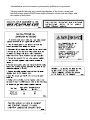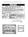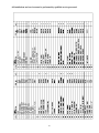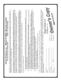
1
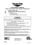
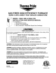
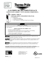
GAS-FIRED OR OIL-FIRED FURNACE
DOWN FLOW & DIRECT VENT (SEALED COMBUSTION)
MODEL: OMD-70
INSTALLATION AND SERVICE MANUAL
For installation in:
1. Manufactured Homes
2. Modular Homes/Buildings
3. Site Construction—Residential (Single Story Dwellings)
:
FOR YOUR SAFETY
Do not store or use gasoline or other flammable vapors and liquids in the vicinity of this or
any other appliance.
WHAT TO DO IF YOU SMELL GAS
• Do not try to light any appliance.
• Do not touch any electrical switch; do not use any phone in your building.
• Immediately call your gas supplier from a neighbor’s phone.
Follow the gas supplier’s instructions.
• If you cannot reach your gas supplier, call the fire department.
: If the information in these instructions is not followed exactly, a fire or explosion may result
causing property damage, personal injury or loss of life.
: Improper installation, adjustment, alteration, service, or maintenance can cause injury or property
damage. Refer to this manual. For assistance or additional information consult a qualified installer, service
agency, or fuel supplier.
: Do not use this appliance if any part has been underwater. Immediately call a qualified service
technician to inspect the appliance and to replace any part of the electrical or control system that has been
underwater.
PLEASE READ THESE INSTRUCTIONS PRIOR TO INSTALLATION, INITIAL FIRING, AND BEFORE
PERFORMING ANY SERVICE OR MAINTENANCE. THESE INSTRUCTIONS MUST BE LEFT WITH THE USER
AND SHOULD BE RETAINED FOR FUTURE REFERENCE BY QUALIFIED SERVICE PERSONNEL.
THERMO PRODUCTS, LLC.
POST OFFICE BOX 217
NORTH JUDSON, IN 46366
PHONE: (574) 896-2133
MO-467
ECN 5135-MA 100615
MADE IN USA
All installations and services must be performed by qualified service personnel.
I. SAFETY SECTION
This page and the following two pages contain various warnings and cautions found
throughout this furnace Service and Installation Manual. Please read and comply with the
statements on the cover and the statements below.
: All local codes and ordinances must be followed with regard to the oil tank and oil
lines. All lines must have shut off valves, use a proper pipe joint compound (specified for use
with oil) on all pipe threads, no kinks, no sharp bends, and be properly tested for leaks. Flare
fittings are recommended for tubing.
: This furnace is not to be used as a construction heater.
: DO NOT RUN THE OIL PUMP DRY FOR MORE THAN FIVE MINUTES.
: When testing electrical equipment, always follow standard electrical procedures
and precautions.
: The heat exchanger must be cleaned by a qualified service person.
: The area around the furnace should be kept free and clear of combustible
materials, especially papers and rags.
: NEVER burn garbage or refuse in your furnace. NEVER try to ignite oil or gas
by tossing burning papers or other material into your furnace.
: Thermo Pride oil furnaces are designed to burn commercial standards of No. 1
and No. 2 fuel oil. NEVER USE GASOLINE OR A MIXTURE OF OIL AND GASOLINE.
: Do not attempt to start the burner when: 1. Excess oil has accumulated 2. The
furnace is full of vapors or 3. The combustion chamber is very hot. If one or more of these
conditions exist, contact a qualified service person.
: If the temperature rise exceeds 100°F, the heat exchanger may fail voiding the
heat exchanger warranty resulting in property damage, personal injury or loss of life.
: Burner adjustments must be confirmed by instrumentation. Failure to use
accurate or calibrated instrumentation to setup the burner may result in reduced efficiency,
sooting and/or the production of hazardous carbon monoxide gas.
: Any attempt to relocate safety controls or replace safety controls with a control
that is not approved or incompatible, may result in personal injury, substantial property
damage or death.
1
All installations and services must be performed by qualified service personnel.
: If you do not follow these instructions exactly, a fire or explosion may result
causing personal injury, loss of life or property damage.
: NEVER use gasoline or a mixture of oil and gasoline to start the burner or
furnace.
: HAZARD OF ASPHYXIATION: Negative pressure inside the closet with closet
door closed and the furnace blower operating shall be no more negative than minus 0.05 inch
water column.
: Do not obstruct any return air openings, including the return grille on the
furnace. To do so may cause the furnace to activate the high limit and shut down or it may
cause asphyxiation.
: Because of the potential of odorant fade, a gas leak may not be detected by smell.
If this furnace is installed below grade, contact your gas supplier for a gas detector.
: All gas pipe connections must be leak tested using a strong soap and water
solution (with the gas turned on). Any leaks must be repaired immediately after turning off the
gas supply. A final test for gas leakage must be made after purging the gas line.
: DO NOT wet electronic components during the leak test. Wetting electronic
components may damage circuitry and cause a hazardous situation. Dry moisture from all
leads and terminals if wetting occurs. Wait at least 24 hours for the circuit to fully dry before
energizing the system.
: The furnace and its gas valve must be disconnected from the gas supply during
pressure testing of the gas supply system at pressures in excess of 1/2 PSIG or 13.9 inches
W.G. The furnace can be isolated from the gas supply by closing its manual shut off valve at
test pressures equal to or less than 1/2 PSIG or 13.9 inches W.G.
: Copper and brass tubing and fittings (except tin lined) shall not be used if the gas
contains more than a trace (0.3 grains per 100 cubic ft.) of hydrogen sulfide gas. Check with
your gas supplier.
: All local codes and ordinances take precedence with regard to tank and oil lines.
All lines must have shutoff valves, a good pipe joint compound approved for use with oil on all
pipe threads, no kinks, no sharp bends and be properly tested for leaks. Flare fittings are
recommended for tubing.
: Do not use motor oil or any fuel other than No. 1 or No. 2 fuel oil in this furnace.
2
All installations and services must be performed by qualified service personnel.
: If you suspect there is a problem with the furnace, the venting system or any other
related problem, immediately contact a qualified service agency. If a service agency is not
available contact your fuel supplier.
: Personal injury, or property damage, could result from major repair or service of
this furnace by anyone other than a qualified contractor. Only the routine maintenance
described in the user section of this manual should be performed by the user.
: The area around the furnace should be kept free and clear of combustible
materials, especially papers and rags.
: Never burn garbage or refuse in your furnace. Never try to ignite oil or gas by
tossing burning papers or other material into your furnace.
: Do not attempt to start the burner when:
1. Excess oil or gas has accumulated.
2. The furnace is full of vapors.
4. The combustion chamber is very hot.
If one or more of these conditions exist, contact a qualified service person.
: Do not block or obstruct air openings on the furnace or air openings
communicating with the area in which the furnace is installed.
: Do not allow the outside air intake to be blocked or obstructed by vegetation, ice,
snow or any other materials.
: Do not use this furnace if any part has been underwater. Immediately call a
qualified service agency to inspect the furnace and to replace any part of the electrical or
control system which has been underwater.
: Should overheating occur or the fuel supply fail to shut off, shut off the manual
fuel supply valve to the furnace before shutting off the electrical supply.
3
All installations and services must be performed by qualified service personnel.
This page and the following page contain reproductions of the various warning and
instruction labels placed on the Thermo Pride Oil Furnace. Please read and comply with
the contents of these labels.
4
All installations and services must be performed by qualified service personnel.
POWER
SWITCH
5
All installations and services must be performed by qualified service personnel.
TABLE OF CONTENTS
SECTION
BEGINNING PAGE
I.
II.
III.
IV.
SAFETY SECTION
GENERAL INSTRUCTIONS AND CLEARANCES
FURNACE SPECIFICATIONS
INSTALLATION
A. ROOF JACK
B. STANDARD CHIMNEY
C. FURNACE LOCATION
D. BASE INSTALLATION
1. Combustible Floor Base Model: 70-BASE
2. Cottage Base Model: OMCCOT-BASE
E. ALCOVE INSTALLATION
F. CLOSET INSTALLATION
G. COMBUSTION AIR
H. FUEL PIPING
1. General Gas Piping
2. Oil Tank and Piping
J. ELECTRICAL WIRING
1. Electrical Branch Supply Circuit
2. Connection of Power Supply Wires
3. Connection of Thermostat Wires
4. Blower Controller Information for PSC Motor
5. Wiring Diagram
K. BURNER INSTALLATION
L. BURNER OPERATION AND ADJUSTMENT
M. FLUE GAS COMBUSTION ANALYSIS
V.
DEALER MAINTENANCE
A. TROUBLESHOOTING
B. CAD CELL CHECKOUT PROCEDURE
C. HEAT EXCHANGER CLEANING INSTRUCTIONS
D. CLEANING OR REPLACING FLUE PIPES
E. EXTENDED SHUTDOWN AND RESTART
VI.
USERS INFORMATION SECTION
A. WARNINGS & CAUTIONS
B. COMPONENT LOCATIONS
C. INSPECTION AREAS
D. FILTER LOCATION AND CLEANING
E. CONTACT INFORMATION
APPENDIX A - REPLACEMENT PARTS LIST
WARRANTY
6
1
7
9
11
11
11
11
13
13
14
16
16
17
20
20
21
23
24
24
24
25
29
30
31
33
34
35
40
40
42
42
43
43
44
44
45
45
46
48
All installations and services must be performed by qualified service personnel.
II. GENERAL INSTRUCTIONS AND CLEARANCES
NOTE: READ THIS SECTION BEFORE STARTING INSTALLATION
1. The selection of a furnace heating capacity for a proposed installation should be based on a
heat loss calculation made according to the manuals provided by the Air Conditioning
Contractors of America (ACCA) or the American Society of Heating, Refrigeration and Air
Conditioning Engineers, Inc. (ASHRAE).
2. The installer shall be familiar with and comply with all codes and regulations applicable to
the installation of this heating appliance. In addition to the governing standards items a) through
e) this appliance shall also comply with “CSA B139 for recommended installation practices”
where applicable.
a. Federal Manufactured Home Constructions & Safety Standard (HUD Total 24, Part 280).
b. American National Standard (ANSI-119.2/NFPA-501C), for all recreational vehicle
installations.
c. American National Standard (ANSI-Z223.1/NFPA-54), for all gas-fired furnaces.
d. American National Standard (ANSI-Z95.1/NFPA-31), for all oil-fired furnaces.
e. American National Standard Electric Code (ANSI-C1/NFPA-70), for all electrical field
wiring.
The oil-fired furnace has been investigated under the UL 307A test standard and the gas-fired
furnace under the UL 307B test standard. Both gas and oil fired units are listed by Underwriters
Laboratories and described as, “For installation as central furnace special type for single story
dwelling.”
: The area around the furnace must be kept free and clear of combustible
materials, especially papers and rags.
: This furnace is not to be used as a construction heater.
1. Definitions of "combustible" and "non-combustible" materials as presented in the 1996
version of the National Fuel Gas Code, ANSI Z223.1-1996/NFPA 70-1996, are as follows:
a. Combustible material:
“...materials made of or surfaced with wood, compressed
paper, plant fibers, or other materials that are capable of
being ignited and burned. Such materials shall be
considered combustible even though flameproofed, fireretardant treated, or plastered.”
7
All installations and services must be performed by qualified service personnel.
b. Non-combustible material:
“...material that is not capable of being ignited and burned;
such as material consisting entirely of, or a combination of,
steel, iron, brick, concrete, slate, asbestos, glass, and plaster.”
This heating appliance must be installed with clearances to combustible material surfaces of not
less than the minimum distances given below. Also, allow ample clearances for servicing the
furnace for easy access to the air filter, blower assembly, burner assembly, controls, and vent
connections.
MODELS OMD/GMD
FRONT
BACK
SIDES
ROOF JACK
VENT CONNECTOR
TOP
PLENUM SIDES
TOP AND SIDES OF DUCT
BOTTOM OF DUCT
CLOSET
6”
0”
0”
0”
6”
1”
1”
1”
1”
8
ALCOVE
18”
0”
0”
0”
6”
1”
1”
1”
1”
All installations and services must be performed by qualified service personnel.
III. FURNACE SPECIFICATIONS
MODEL
OMD-70
GMD-85
HEAT INPUT RATE (BTUH)
85,000
HEATING CAPACITY (BTUH)
71,000
BURNER NOZZLE (GPH X
ANGLE, HOLLOW CONE)
0.65X80A
BURNER ORIFICE-NAT. GAS
--------BURNER ORIFICE-PROP. GAS
--------OIL PUMP PRESSURE (PSIG)
100
GAS SUPPLY PRESSURE (IN.W.G.)
MINIMUM REQUIRED
PROPANE
--------NATURAL
--------MAXIMUM ALLOWED
PROPANE
--------NATURAL
--------GAS MANIFOLD PRESSURE (IN. W.G.)
PROPANE
--------NATURAL
--------VENT PIPE SIZE (INCHES)
4
DESIGN TEMPERATURE RISE (°F) 85
MINIMUM RETURN AIR TEMP. (°F) 55
SEASONAL EFFICIENCY
(AFUE*, %)
85
85,000
69,700
------#17 DMS
#36 DMS
-------
11
4.5
13.9
13.9
10 + 0.3
3.5 + 0.3
4
85
55
82
*AFUE - INCLUDES STEADY STATE THERMAL EFFICIENCY AND OFF CYCLE
LOSSES.
ELECTRICAL RATINGS AND SETTINGS:
ELECTRICAL SUPPLY: 120 VAC / 60HZ / 1 PHASE
MAXIMUM TIME DELAY TYPE FUSE OR HACR BREAKER RATING: 15 AMPS
TOTAL RATED CURRENT (AMPS): 11.3 (OMD), 6.81 (GMD)
NOMINAL HEAT ANTICIPATOR SETTING -- 0.2 mA (OMD), 0.8 mA (GMD)
DIMENSIONS & WEIGHTS:
CABINET: WIDTH - 18 IN., DEPTH - 24 IN., HEIGHT - 57 IN.
NO.70 MOBILE HOME BASE: WIDTH - 18 5/16 IN., DEPTH - 24¼ IN., HEIGHT - 4 IN.
WARM AIR DUCT: WIDTH – 12 IN., DEPTH – 12 IN., HEIGHT - 14 ¼ IN.
COTTAGE BASE: WIDTH – 18 3/16 IN., DEPTH - 24¼ IN., HEIGHT – 14¾ IN.
FILTER QUANTITY & SIZE: (2) @ 17 ¾ IN. x 13 ¾ IN. x 1 IN. EA.
APPROXIMATE SHIPPING WEIGHT: 240 LBS.
PRODUCT LISTED UNDER UL FILE NUMBER -- MP3241
9
All installations and services must be performed by qualified service personnel.
BURNER DATA
OMD-70
GMD-85
MANUFACTURER: R.W. BECKETT CORP.
MODEL:
AFG
AIR TUBE LENGTH (IN.):
3-5/8
HEAD DESIGN:
F-3
REFRACTORY TYPE:
MHC (FIBER)
OIL PUMP
PRESSURE (P.S.I.G.)
100
WAYNE COMBUSTION SYSTEMS
P265 FEP
3-5/8
-------MHC (FIBER)
--------
FOR BURNER COMBUSTION INFORMATION, REFER TO SECTION (M) – FLUE GAS
COMBUSTION ANALYSIS.
BLOWER DATA
MANUFACTURER: MORRISON PRODUCTS, INC.
BLOWER MODEL:10-7, DIRECT DRIVE
NOMINAL MOTOR POWER OUTPUT (HORSEPOWER): 1/5
NOMINAL MOTOR SHAFT SPEED (RPM): 1075
TYPICAL AIRFLOW ON LOW FAN SPEED
@ SPECIFIED EXTERNAL
STATIC PRESSURES (SCFM @ .IN.W.G.):
780 @ 0.2,
650 @ 0.5
ALL SPECIFICATIONS ARE SUBJECT TO CHANGE WITHOUT NOTICE.
10
All installations and services must be performed by qualified service personnel.
IV. INSTALLATION
A. ROOF JACK
The roof jack assembly and accessories must be listed by a nationally recognized testing agency
for the appropriate fuel.
The roof jack assembly must be installed according to the vent manufacturer’s instructions prior
to the furnace installation. (Refer to Figure 2 for flue location on furnace.) Adapters for pitched
roofs as well as extended barrel length roof jacks are available from Thermo Products.
All vent seams and connections must be sealed with high temperature silicone caulk and/or high
temperature aluminum tape.
B. STANDARD CHIMNEY
When installed as a central furnace special type for single story dwelling, venting into a metal
vent system approved by a nationally recognized testing agency for the appropriate fuel type is
permitted. Lined masonry chimneys are acceptable when sized appropriately. The minimum
chimney size should equivalent to the inside free area of the 4-inch diameter vent collar exiting
the furnace, or 12.5 square inches.
Maximum chimney sizes and acceptable installation practices are referenced in the following
publications. In lieu of local codes, when installing the OMD-70 with fuel oil, refer to the latest
edition of the installation standard NFPA 31, Installation of Oil Burning Equipment. When
installing the GMD-85 with natural or LP gases, refer to Appendix G of the latest edition of the
installation standard NFPA 54, National Fuel Gas Code.
Notice: Blocked Vent Switch Installation for cottage type homes or non-mobile home type
dwellings. The blocked vent switch kit must be installed to comply with CAN STD B140.4
where applicable. For installation instructions see AOPS2686 kit.
C. FURNACE LOCATION
1. For best performance, locate the furnace so that it is centralized with respect to the duct
system.
2. This furnace is only intended for installation with free air return through the furnace door
louvers. DO NOT connect a ducted return air system directly to the furnace. Improper
installation may create a fire hazard and damage internal equipment, as well as void all
manufacturer’s warranties.
3. This furnace may be installed on combustible flooring when utilizing either the No. 70
counterflow floor base, for below the floor duct systems, or with the cottage base, for floor
level air distribution. See Figures 1 for depictions of the No. 70 and the cottage bases.
11
All installations and services must be performed by qualified service personnel.
4. This furnace is U.L. listed for closet, alcove or freestanding applications. All applications
must comply with the requirements of this manual.
Combustible Floor Base
Model: 70-BASE
Figure 1A.
Cottage Base
Model: 01COT-BASE
Figure 1B.
D. BASE INSTALLATION
12
All installations and services must be performed by qualified service personnel.
1. Combustible Floor Base Model: 70-BASE
Use the base bottom panel as a template to mark floor opening locations (see Figure 2). Cut a
square opening in the floor for the supply air connector duct. Cut the opening 1-inch larger
than the square template opening. (duct requires 1-inch clearance to combustible floor). Cut a
combustion air duct opening in the floor 1/8-inch larger than the template opening.
Figure 2.
After cutting openings in the floor, place the bottom panel in position. Mark the square
opening location on the distribution duct at the connection point of the connector duct.
Remove the bottom panel. Cut an opening in the distribution duct slightly larger than the
connector duct. (refer to Figure 2 for location of this cut.) Cut the connector duct to length.
Install the connector duct. Bend over each tab. Insure an airtight seal by using high
temperature sealant or tape on the joint. Reinstall the bottom panel over the connector duct.
Insert and secure the combustion air duct. Put the base top assembly in place (see Figure-3).
IMPORTANT: A combustion air duct must be used. If the underside of the mobile home is
skirted or enclosed (e.g. enclosed in a crawlspace), the combustion air intake should exit
through the skirting, or enclosure, if at all possible. All joints and seams of supply ducts and
combustion air ducts must be closed with a sealing method suitable to the application
conditions and temperatures ( e.g. high temperature silicone caulk and/or aluminum tape).
13
All installations and services must be performed by qualified service personnel.
If the combustion air passageway cannot terminate outside of the skirting or enclosure, a
permanent opening with a minimum of 50 square inches of unobstructed infiltration (free
area) for ventilation air must be provided for adequate combustion. This permanent opening
must be located no less than 12 inches from the bottom of the enclosure or skirting.
Figure 3.
Slit the corners of connector duct down to the top of the base assembly. If metal projects more
than 1-inch above the top of the base assembly, trim the flanges down to 1-inch. While the top
of distribution duct is being pulled up with one hand, bend down each side of the connector
duct tightly to the base assembly with the other hand. This assures a tight connection between
the base assembly and the connector duct and that the distribution duct will be full size. Use
high temperature tape and/or high temperature silicone caulking on all joints and seams to
minimize air leakage. Secure the base assembly to the floor with two screws in the front
flange.
2. Cottage Base Model: OMCCOT-BASE
The OMCCOT-BASE cottage base (Figure 1B) is required for a freestanding cottage base
installation. The cottage base is designed to permit the installation of an 8-inch x 12-inch register
in each of the two side panels and the rear panel. This allows combustion air to be drawn from
outside, or inside, the structure whichever is appropriate, or permissible. See section G.
COMBUSTION AIR for further details regarding combustion air requirements.
14
All installations and services must be performed by qualified service personnel.
IMPORTANT: Adequate combustion air must be provided under all circumstances. If the
underside of the home is skirted or enclosed (e.g. by an enclosed crawlspace), the combustion
air intake should exit through the side of cottage base and terminate outside of the structure.
All joints and seams of supply ducts and combustion air ducts must be closed with a sealing
method suitable to the application conditions and temperatures (e.g. using high temperature
silicone caulk and/or aluminum tape).
If the combustion air passageway cannot terminate outside of the structure, a permanent
opening with a minimum of 50 square inches of unobstructed infiltration (free area) for
ventilation and combustion air must be provided to the interior of the structure. Additional
make-up air may need to be supplied to the interior of the structure to compensate for exhaust
fans, appliances, or vents which consume air from the interior of the structure.
Refer to the assembly installation instructions included with OMCCOT-BASE cottage base for
additional information.
15
All installations and services must be performed by qualified service personnel.
E. ALCOVE INSTALLATION
In this application, a minimum of 18 inches of
clearance must be provided to the front of the unit.
Refer to Figure 4.
Alcove installations must use the No. 70 mobile
home base.
Note – access to diagnostic view port.
Refer to section G. COMBUSTION AIR for
additional combustion air requirements.
Figure 4.
F. CLOSET INSTALLATION
: HAZARD OF
ASPHYXIATION: A suction effect
will occur when the furnace is
operating inside the closet with the
closet door closed. For proper
operation, the furnace blower shall
create no more than a 0.05-inch water
column pressure differential between
the closet and the adjoining space.
Figure 5.
1. The return air opening into the
closet is to have a minimum free
area of 250 square inches, (refer to
Figure 5).
16
All installations and services must be performed by qualified service personnel.
2. The return air opening may be located in the top, the center or (ideally) the bottom of the
closet door, or side wall.
: Do not obstruct any return air openings, including the return grille on the
furnace. To do so may cause the furnace to activate the high temperature limit and shutdown,
or it may cause asphyxiation.
3. The cross-sectional area of the return air duct leading into the closet (when located in the
floor or ceiling) shall not be less than 250 square inches.
4. The total free area of openings in the floor or ceiling registers serving the return air duct
system must be at least 350 square inches. At least one register must be located where it is
not likely to be covered by carpeting, boxes, furniture, or any other objects.
5. Materials located in the return duct system must have a flame spread classification of 200 or
less.
6. Pans made of a non-combustible material having 1 inch upturned flanges are to be located
beneath openings in a floor, return air, duct system.
7. Wiring materials located in the return air duct system must conform to Article 300-22 of the
latest edition of the National Electrical Code, NFPA 70.
8. Gas piping shall not be located in, or extend through, the return air duct system.
9. Refer to section G. COMBUSTION AIR for additional combustion air requirements.
G. COMBUSTION AIR
The furnace requires the proper amount of combustion air be available to combust the fuel
cleanly and efficiently. An inadequate combustion air supply can result in unsafe and erratic
operation of the burner, sooting of the combustion chamber and the heat exchanger, and
possibly, offensive fuel odors. The combustion air intake must provide an adequate source of
combustion air to the appliance. Refer to part 5.3 of the National Fuel Gas Code, ANSI Z223.1 /
NFPA 54-1999, or latest edition for application specific combustion air requirements.
17
All installations and services must be performed by qualified service personnel.
The preferred location of the outside combustion air intake termination (e.g. an optional stainless
steel intake hood, part no.370183) is through the side of the structure, skirting or enclosure. An
alternate termination location is under the structure in the skirted or crawlspace area providing a
minimum of 50 square inches of free area exists around the perimeter for outside combustion air
to be drawn through. NOTE: Combustion air cannot be drawn from the occupied space of the
home.
The furnace is shipped with a combustion air duct that must be installed in the bottom of the
burner enclosure, before the burner is installed. This 2-inch by 7-inch duct is shipped in two
pieces. High temperature silicone sealant should be applied to both vertical seams, before it is
snapped together with four flanges on one end. The duct must then have high temperature
silicone applied to the flanges. Then, the combustion air duct can be inserted through the
opening in the floor base model no.70. When the combustion air duct has been inserted
completely, secure the duct to the combustion adapter with self-tapping sheet metal screws, refer
to Figure 6. Make certain that the flanges, duct, and adapter are completely sealed to the burner
enclosure base with high temperature silicone caulk.
NOTE: The adapter may be cut with sheet metal shears to the appropriate size and secured over
the inlet air duct opening. The adapter will convert the rectangular opening to a round connector
ring. The ring will allow the connection of 2-inch I.D. flexible hose (provided) between the
adapter and the inlet air boot, attached to the burner. Secure both ends of the flex hose with hose
clamps (provided).
A 2-inch round to 7-inch x 4-inch rectangular, sheet metal, transition boot is supplied with the
furnace for adapting a 4-inch round combustion air duct to the 2-inch x 7-inch combustion air
duct. This boot has a screen inserted into the 4-inch round portion of the boot to provide a degree
of protection from pests entering the furnace when the boot is terminated in the crawl space, or
skirted area, directly below the furnace.
The material recommended for the combustion air duct is smooth, round, galvanized steel duct
or schedule 20 PVC pipe. The maximum duct length allowed is equivalent to 40-feet of straight
duct. Reduce this length by 6-feet for the intake hood and each 90-degree elbow used, and by 3feet for each 45-degree elbow used the combustion air duct. Flexible, spiral, or corrugated duct is
not recommended, due to the relatively high pressure drop associated with air movement through
this type of passageway.
18
All installations and services must be performed by qualified service personnel.
Figure 6.
19
All installations and services must be performed by qualified service personnel.
H. FUEL PIPING
Sizing and installation of fuel lines must be in accordance with federal, state and local
regulations.
1. General Gas Piping (GMD-85)
: Because of the potential of the odorant to fade, a gas leak may not be detected by
smell. If this furnace is installed below grade, contact your gas supplier for a gas detector.
A qualified installer or service person must install all gas piping and perform all required testing.
Piping from the natural gas meter to the furnace shall be in accordance with requirements of the
local gas utility. Piping from the propane tank to the furnace must follow the recommendations
of the gas supplier. In the absence of local codes governing gas piping selection and installation,
follow the National Fuel Gas Code, ANSI Z223.1 / NFPA 54-1999, or latest edition.
A readily accessible, manual gas shutoff valve (design-certified for the applicable gas) with a
non-displaceable rotor member shall be installed within six feet of the furnace.
A pipe union, or flanged connection, shall be provided directly up stream of the burner to allow
burner removal. Unions must be of a ground joint type or flange-jointed type using a gasket
resistant to the corrosive effects of LP gases. Pipe dope or sealant design-certified to be resistant
to the action of the LP gases should be used on all threaded joints.
The burner is setup to be piped to the gas supply through the left-hand side of the furnace. For
service purposes, it is recommended the gas union be located inside the furnace.
A drip leg must be used on both propane and natural gas installations immediately upstream of
the furnace in order to trap oil, condensate, and other impurities which might otherwise lodge in
the gas valve, or plug the main burner orifice. A drip leg shall be provided at the outlet of the gas
meter when there is excessive condensation between the gas meter and the furnace.
Failure to install drip leg(s) may void the manufacturer’s limited warranty on the furnace.
: With the gas piping pressurized, all gas piping connections must be leak tested
using a strong soap and water solution. Any leaks must be repaired immediately after turning
off the gas supply. A final test for gas leakage must be made after purging the gas line.
: DO NOT wet electronic components during the leak test. Wetting electronic
components may damage circuitry and cause a hazardous situation. Dry moisture from all
leads and terminals if wetting occurs. Wait at least 24 hours for the circuit to fully dry before
energizing the system.
20
All installations and services must be performed by qualified service personnel.
: The furnace and its gas valve must be disconnected from the gas supply during
pressure testing of the gas supply system at pressures in excess of 1/2 PSIG (13.9 inches
W.G.). The furnace can be isolated from the gas supply by closing the manual gas shutoff
valve serving the appliance at test pressures equal to, or less than, 1/2 PSIG or (13.9 inches
W.G.).
: Copper and brass tubing and fittings (except tin lined) shall not be used if the gas
contains more than a trace (0.3 grains per 100 cubic ft.) of hydrogen sulfide gas. Check with
your gas supplier.
For natural gas, the maximum supply pressure is 13.9 in. W.G. and the minimum supply
pressure, for purposes of input adjustment, is 4.5 in. W.G.
For propane gas, the maximum supply pressure is 13.9 in. W.G. and the minimum supply
pressure, for purposes of input adjustment, is 11.5 in. W.G.
2. Oil Tank and Piping (OMD-70)
: All local codes and ordinances take precedence with regard to tank and oil lines.
All lines must have oil shutoff valves, a good pipe joint compound approved for use with oil on
all pipe threads, no kinks; no sharp bends and be properly tested for leaks. Flare fittings are
recommended for tubing.
: Do not run the oil pump dry for more than five minutes.
Your furnace is factory equipped to operate on No. 2 distillate fuel (domestic heating) oil. In
very cold weather, No. 1 distillate fuel oil may be used. Your oil supplier should be contacted for
recommendations.
: Do not use motor oil or any fuel other than No. 1 or No. 2 fuel oil in this furnace.
Burners are most commonly installed with a single stage fuel pump (refer to Figure 7). This type
of fuel pump, when connected with a supply line only, is satisfactory where the fuel supply is
level with, or above, the burner. This type of installation permits gravity flow of oil to the
burner. When it is necessary to “lift” (raise) oil to the burner, a return line should be connected
between the fuel pump and tank. This requires insertion of the “by-pass” plug into the fuel pump.
If the lift exceeds approximately 10 feet, a two-stage pump should be installed with a return line.
When a return line is used with either single or two-stage pumps, air is automatically returned to
the tank, making the unit self-purging.
Use of continuous runs of heavy wall copper tubing is recommended. Always use flare fittings.
Avoid use of fittings in inaccessible locations. Avoid running tubing against any type of
heating unit and across ceiling or floor joists.
21
All installations and services must be performed by qualified service personnel.
If possible, install the tubing under the floor. Specific information on piping, fuel pump
connections, lift capabilities and tank installations is provided in the fuel pump manufacturer’s
instructions.
If the oil tank is located inside the building and the tank capacity is between 10 and 660
gallons, it shall not be located within 5 feet horizontally from any source of heat, or oilburning appliance. Furthermore, the oil tank shall not block access to utility service
meters, switch panels, and shutoff valves.
If an underground tank used, the top of the tank should be below all piping in order to prevent oil
discharge through a broken connection. Underwriters Laboratories requirements now stipulate
that all 275 gallon and larger tanks have a bottom outlet. This is to prevent the accumulation of
condensate, which causes the tank to rust. It is also recommended to use a water trap or additives
to prevent condensate accumulation.
If the tank is above the burner, and gravity oil feed to the burner is permitted, a single line
system may be used. The line should have a gradual slope downward of approximately 1/2 inch
per foot, or more, to a point directly below where it is connected to the pump. Installing the line
with a downward slope will help prevent the formation of air pockets in the line.
IMPORTANT: An oil safety valve or a delayed-action solenoid valve is required with all
gravity feed oil supply systems.
IMPORTANT: The oil storage tank must be free of water, sludge and scale to prevent
excessive wear and possible damage to furnace oil pump and burner nozzle. A fuel oil filter
installed in the oil supply line to the burner is required.
OIL FILTER: For all installations, use a low micron, oil filter with the capacity to trap particles
10 microns in diameter, or greater. Filtering the oil supply helps to prevent nozzle clogging.
Install the oil filter inside the building between the tank shutoff valve and the burner. The filter
cartridge should be replaced at least once a year. The filter body should be thoroughly cleaned
before installing a new cartridge.
22
All installations and services must be performed by qualified service personnel.
Figure 7.
J. ELECTRICAL WIRING
All electrical wiring must be installed in strict accordance with local ordinances and codes. In
the absence of local ordinances and codes, all electrical wiring must conform to the requirements
of the National Electric Code, ANSI/NFPA 70-1999, or latest edition.
23
All installations and services must be performed by qualified service personnel.
: When testing electrical equipment, always follow standard electrical procedures
and precautions.
1. Electrical Branch Supply Circuit
Route all electrical wiring to the left side of the furnace. The power supply circuit to the
furnace must be installed and grounded in accordance with the provisions of the National
Electrical Code, ANSI/NFPA-70-1999, or latest edition, and all local codes having
jurisdiction. Electrical Branch Supply Circuit provisions of the Canadian Electrical Code
Part 1 shall be observed and followed where applicable.
2. Connection Of Power Supply Wires
a. Remove the furnace control panel cover.
b. Insert 120 VAC wires through the strain relief bushing (or conduit connection as
applicable) on the left side of the furnace junction box.
c. Connect the “Hot” wire to the black wire marked “L1”.
d. Connect the “Neutral” wire to the white wire marked “L2”.
e. Connect the “ground” wire to the ground lug.
3. Connection Of Thermostat Wires
NOTE: Class 1 thermostat wire must be used inside the furnace burner compartment.
a. Insert 24 VAC wires through the plastic grommet on the left side of the furnace casing.
b. Connect the thermostat wires to “R” and “W” for heating.
c. Connect the thermostat wires to the room thermostat.
IMPORTANT: The room thermostat should be installed 4 to 5 feet above the floor on
interior wall which is relatively free from direct sources of heat (sunlight or supply airflow)
or exposure to cold (drafts from open windows and doors). The nominal anticipator settings
are 0.8 amperes, for the GMD, and 0.2 amperes, for the OMD (refer to the thermostat
literature for additional information).
Five-conductor thermostat wire is recommended for 24 VAC, low-voltage, control circuit
wiring. Only 2 wires are required for the furnace (a heating application only).
Electrical Wire Diameter
Maximum Recommended
Thermostat Wire Length
(AWG)
(feet)
24
22
20
18
55
90
140
225
24
All installations and services must be performed by qualified service personnel.
Once the furnace is installed, check the thermostat heat anticipator the proper nominal
setting.
a. Connect a multimeter, capable of reading milliamps (mA), in series with the low voltage
wires to the thermostat.
b. Increase the thermostat setting, or create a “call for heat”.
c. Read the value of the thermostat current, in milliamps.
d. Adjust the heat anticipator of the thermostat to the value read by the multimeter.
If the heat anticipator is set too high, the furnace may delay activation of a heating cycle for
too long. If the heat anticipator is set too low, the furnace may cycle too frequently. Either
condition may not provide optimal comfort to the homeowner.
4. BLOWER CONTROLLER INFORMATION FOR PSC MOTOR
TERMINAL DEFINITIONS & FIELD WIRING
Burner Harness Connector P1
Pin 1- Limit switch connector.
Pin 2- 120 VAC Line connection.
Pin 3- Burner pilot contact.
Pin 4&5120 VAC Neutral connections.
Pin 6- Burner pilot contact.
Pin 7&8From oil primary control.
Pin 9- Limit Switch Input (LSI).
Field Wiring to Burner
Harness Wires
Beckett Connections
Pilot (Tstat)
Yellow Wires
T-T terminals
Neutral
White
White
Line
Red
Black
Thermostat / Humidistat connections
“C”
Common / ground
“W”
Thermostat call for heat
“R”
24 VAC to thermostat
“G”
Thermostat call for fan
“Y”
Thermostat call for cool
“DEHUM”
Humidistat call for dehumidification (TXV systems ONLY)
Male quick connect terminals.
“S1-3”
120 VAC Hot
“N1-7”
120 VAC Neutral
“EAC”
Electronic Air Cleaner (120 VAC) connection
“FAN”
Fan On Signal
“X”
24 VAC from transformer
25
All installations and services must be performed by qualified service personnel.
“C”
“CC”
“CC_COM”
“LOW”
“HEAT”
“COOL”
24 VAC common from transformer
Compressor Contactor
Compressor Contactor Common
Continuous Blower Speed
Blower heat speed tap
Blower cool speed tap
A. Inputs
Power supplies
Line voltage is applied between the “S1” and “N1” quick connect terminals. 24 VAC Class II Transformer
secondary voltage supplied to X and C
Limit switch
The 120 VAC optically isolated limit switch input is connected on pin P2-1 & 9. Refer to the Heat Mode
section for the control operation.
Thermostat call for heat “W”
24 VAC thermostat input. A call for heat is recognized when the thermostat connects “W” to “R”. This input
has an indicator LED that will light when the control receives a call for heat. Refer to the Heat Mode section
for the control operation.
Thermostat call for fan “G”
24 VAC thermostat input. A call for fan is recognized when the thermostat connects “G” to “R”. This input
has an indicator LED in that will light when the control receives a call for fan. Refer to the Fan Mode
section for the control operation.
B. Outputs
PSC Control
The control shall control a five speed indoor blower motor. Rating shall be 10 FLA, 30 LRA @ 120 VAC.
Connections are made via 0.250 x 0.032” male quick connect terminals labeled “HEAT”, “COOL”, and
“LOW”. “HEAT” is energized when the heat speed blower is to run. “COOL” is energized when the Cool
speed blower is to run. “LOW” is energized during a call for fan is received or a call for dehumidification
is received.
Oil Burner
Control
The control provides dedicated contacts to operate the T-T input of an oil primary control.
Rating shall be class 2 – 24 VAC pilot duty @ 24 VAC (<200mA).
Power
The switched 120 VAC power from the LIMIT switch passes through the board between Pins 1 & 2 of
connector P1.
EAC (electronic air cleaner)
26
All installations and services must be performed by qualified service personnel.
The control provides a 120 VAC output for an electronic air cleaner. This output is energized whenever the
fan motor is energized (either low, heat or cool speed). Connection is made via male quick connect
terminal labeled “EAC”.
Humidifier
The control provides a 120 VAC output for a humidifier. Connections are made to a male quick connect
terminal labeled “FAN”. The control does not switch this output, it provides a pass-through connection
from P1-7 from the switched primary voltage of the Burner Module.
Status LED
A red LED is provided to indicate any thermostat input has been recognized by the microprocessor on the
control. See Diagnostic Features for a function description of operation.
Thermostat Input LEDs
Four green LEDs are placed beneath their respective thermostat connections (W, Y, G and DEHUM) and
operate whenever a call is present. See Diagnostic Features for a function description of operation.
C. Operating Modes
Standby Mode
All outputs are off and the control is waiting for a thermostat demand. The thermostat inputs, and limit
switch are continuously monitored. The control initiates action when a thermostat call is received or limit
switch opens.
Fan Mode
A call for fan (“G”) is received from the thermostat. If no other mode is calling for blower operation, the
control will operate the fan relay (K4) and power the “Low” blower speed terminal. The fan mode will be
operated as long as the “G” input is calling and neither the Heat mode nor the Cool mode is calling for
blower operation. When the Heat and Cool modes call for blower operation, their respective outputs will
take precedence after their respective turn-on time delays have expired.
Heat Mode
When a call for heat (“W”) is received from the thermostat, if the “Cool” mode is not already active, the
“T-T” terminal is energized and the blower on delay is started. The on-off pattern of DIP switch SW2
(positions 1 and 2) select one of four blower on delay values (see Table 11). When the delay time has
elapsed, the “HEAT” blower speed is energized. The control remains in steady heat mode until the
thermostat is satisfied. When the call for heat signal is removed, the “T-T” terminal is de-energized and the
blower off delay is started. The on-off pattern of DIP switch SW2 (positions 3 and 4) select one of four
blower off delay values (see Table 11). When the delay time has elapsed, the “HEAT” blower speed
terminal is de-energized.
27
All installations and services must be performed by qualified service personnel.
DIP SWITCH 2 SECTION STATE
FACTORY
SETTING
1
2
OFF
OFF
30
ON
OFF
60
OFF
ON
120
ON
ON
240
FACTORY
SETTING
3
BLOWER DELAY TIMES
4
ON - SEC
OFF - MIN
OFF
OFF
2
ON
OFF
4
OFF
ON
6
ON
ON
8
Table 11: ON and OFF Blower Delay Time Switch Settings
Blower On and Off Delays
Four Heat blower on and four blower off delays are selected by two dip switches for each function. Refer
to Table 11 for specific delay values.
PSC TROUBLE SHOOTING
DIAGNOSTIC FEATURES
The control board is equipped with 4 green Input Status LEDs and 1 red Board Status LED. These are
intended to provide a quick view into furnace performance without requiring a voltmeter.
The green Input Status LEDs are driven by the “Y”, “W”, “G”, and “DEHUM” inputs and are located
directly below those inputs. They will light to indicate the presence of these signals.
The red Board Status LED has two functions:
It will light when the board recognizes a valid input signal and will stay lit until all valid signals are
removed. This is intended to show that the board is functioning and able to respond to input signals.
It will flash rapidly while 120VAC is missing from the LIMIT switch. This is intended to give a quick
visual indication of the High Limit switch.
28
All installations and services must be performed by qualified service personnel.
5. WIRING DIAGRAM
29
All installations and services must be performed by qualified service personnel.
K. BURNER INSTALLATION
The burner mounts to the furnace on three mounting bolt studs, located on the burner mounting
plate, in the lower portion of the vestibule, directly in front of the heat exchanger.
The burner insertion depth has been fixed by the factory for the design-specified, combination of
the air tube length and the combustion chamber used with the furnace. The combustion chamber
is pre-positioned during the assembly process and held in place by the drum and mounting plate.
The burner insertion depth is not field-adjustable.
Should access to the chamber be necessary, refer to the exploded diagram, in the back of this
manual, to identify replacement parts.
To install and ready the burner for firing, follow the steps below for both furnace models.
1. With electrical power connected to the furnace, turn off all electrical power to unit.
2. Remove the front lower access panel.
3. Mount the burner to the furnace. Install the flange gasket over the mounting studs and
secure the burner flange to the furnace using hex head machine screw nuts, provided in
the Parts Kit.
4. Connect the red and white wires from the burner harness to the black, red and white
burner power leads found underneath the primary control. Then connect the two yellow
wires to the “T & T” terminals on the front of the primary control.
For the oil burner installation (OMD) only:
5. Determine whether an oil return line is required and connect the fuel oil piping to the
burner oil pump through the base of the unit.
6. Turn on electrical power to the furnace. Cause or simulate a “call for heat” to bleed
air from the oil line at the oil pump. (Temporarily, connect the two thermostat leads
to cause the oil pump to run.)
7. With all oil shutoff valves open, open the air-bleed valve on the oil pump and capture
the oil flow in a container until all traces of air in the line are gone.
8. Close the air-bleed valve. Check for and correct any oil leaks. The furnace is now
ready for burner adjustment. Refer to the following “BURNER OPERATION AND
ADJUSTMENT” section.
For the gas burner installation (GMD) only:
5. Connect the gas piping to the burner through the base of the unit.
6. With all gas shutoff valves open, bleed air from the gas line by opening the pipe
union closest to the furnace a small amount. Carefully, close the pipe union when the
odor of gas becomes strong. Check for and correct any subsequent gas leaks.
Wait five (5) minutes for any lingering gas to dissipate.
7. Turn on electrical power to the furnace.
30
All installations and services must be performed by qualified service personnel.
8. The furnace is now ready for burner adjustment, refer to the following “BURNER
OPERATION AND ADJUSTMENT” section.
L. BURNER OPERATION AND ADJUSTMENT
: NEVER burn garbage or refuse in the furnace. NEVER try to ignite oil or gas by
tossing burning papers or other material into your furnace.
: If you do not follow these instructions exactly, a fire or explosion may result
causing personal injury, loss of life or property damage.
: NEVER use gasoline or a mixture of oil and gasoline to start the burner or
furnace.
1. Qualified service personnel must perform the first lighting of the burner.
2. The burner instructions must be read and understood before any attempt is made to
light this burner.
NOTE: For the sequence of burner operations, see individual burner manual. To
successfully service and initially set up this furnace you must use the following
instruments:
[Items (a)-(e) ... apply to both oil and gas furnaces), item (f) ... applies to gas units only,
and items (g)-(h) ... applies to oil units only]
a. Carbon dioxide (CO2) or oxygen (O2) analyzer.
b. Flue gas thermometer (range 100°F to 1000°F) and temperature-measuring
device (range -40°F to 240°F, for return and supply air temperatures).
c. Carbon monoxide (CO) detector
d. Electrical multimeter
e. Liquid, U-tube type manometer or equivalent pressure measuring instrument
(range: 0 – 28 in.W.G.)
f. Smoke spot tester or equivalent smoke density measuring device
g. Oil pressure gauge (range: 0-150 PSIG)
h. Vacuum gauge (range: 0-30 in. W.G. vacuum)
Turn the main service switch that provides power to the furnace to the “off” position. Set
thermostat above room temperature. Open all fuel supply valves. Bleed air out of fuel
supply line, if not already completed (for oil, power must be “on” to the burner and the
pump must be operating to expel air in the supply line).
When ignition is established, if necessary, make a preliminary burner air adjustment to
attain a clean combustion flame (one which does not create smoke by eye). On the GMD
unit, the flame may be viewed through a sightglass mounted on the burner. On both units,
the flame may be viewed through the overfire inspection cover (see exploded diagram of
31
All installations and services must be performed by qualified service personnel.
replacement parts for location identification). After the furnace is warmed up to a steadystate condition (about 15 minutes), the final burner adjustment should be made using
combustion instrumentation for measuring carbon dioxide (CO2) or oxygen (O2), carbon
monoxide (CO), smoke (for oil furnaces), and stack temperature. In order to achieve the
most efficient combustion possible, the following steps must be taken.
IMPORTANT: To achieve proper combustion and efficiency instruments must be used
to secure CO2, O2 and CO readings.
1. CARBON DIOXIDE (CO2) or OXYGEN (O2): Take a CO2 sample from the flue pipe
or vent connector at a position close to the furnace. It is possible to achieve relatively
high CO2 (or low O2) readings with low stack temperatures to produce maximum
combustion efficiency. However, the CO2 and O2 values recommended are slightly
less, though this means slightly lower efficiency, to allow the burner to better tolerate
adverse operating conditions, such as a cold heat exchanger, downdraft conditions,
heating content changes in the fuel. This working tolerance means less service and
maintenance during heating seasons as well as a reduced chance of producing carbon
monoxide under adverse conditions.
2. CARBON MONOXIDE (CO): As described above, take a flue gas sample from the
flue pipe or vent connector at a position close to the furnace. The amount of CO
generated by combustion ideally should be zero or only a trace. In all cases, it must
be less than 50 PPM. Carbon monoxide is a colorless and odorless gas, but it is toxic
compound. The production of significant quantities of CO is a strong indicator of
incomplete combustion. Check the fuel supply and the burner for fuel leakage. Check
for an inadequate supply of clean air for combustion. Also, check for a restricted or
blocked flue, vent, or chimney.
3. SMOKE: (oil burners only) A smoke sample should be drawn from the flue pipe or
vent connector at a position close to the furnace. For the greatest efficiency, if the
first smoke reading is “0”, close the air shutter on the burner until a trace smoke
reading is obtained.
4. FLUE GAS TEMPERATURE: The flue gas temperature will vary to some degree
depending on the heating content of the fuel, the amount of combustion air, and
airflow across heat exchanger. In general, the lower the stack temperature, the higher
the efficiency. However, stack temperatures under 350°F may cause flue gases to
condense, which in turn may cause excessive metal corrosion.
5. TEMPERATURE RISE: Supply air temperature (measured twelve inches into trunk,
away from radiant heat from the furnace) minus (-) return air temperature, or
Temperature rise = Supply air temperature - Return air temperature.
The temperature rise across the furnace heat exchanger operating at steady-state
conditions (about 15 to 20 minutes) should not exceed 100°F. The normal comfort
32
All installations and services must be performed by qualified service personnel.
range is between 70°F to 100°F. A lower temperature rise usually results in a higher
system efficiency.
: If the temperature rise exceeds 100°F, the heat exchanger may fail, voiding
the heat exchanger warranty resulting in property damage, personal injury or loss of
life.
M. FLUE GAS COMBUSTION ANALYSIS
: Burner adjustments must be confirmed by instrumentation. Failure to use
accurate or calibrated instrumentation to correctly setup the burner may result in
reduced efficiency, sooting, and/or the production of hazardous carbon monoxide gas.
For typical burner combustion analysis results, refer to the table below.
BURNER COMBUSTION PARAMETERS
FURNACE MODEL
OMD-70
GMD-85
FUEL TYPE
#1 OR #2 FUEL OIL NATURAL GAS PROPANE GAS
CO (CARBON MONOXIDE)
50PPM OR LESS
50PPM OR LESS 50PPM OR LESS
CO2 (CARBON DIOXIDE)
11-12%
8.75-10%
9.5-11%
O2 (OXYGEN)
4.5-6%
5.9-3.8%
6.7-4.5%
SMOKE SPOT RATING
0 TO TRACE
N/A
N/A
AIR SHUTTER
OPEN TO
OPEN TO
OPEN TO
ADJUSTMENT
POSITION 35
POSITION 4
POSITION 4
N/A = NOT APPLICABLE
33
All installations and services must be performed by qualified service personnel.
V. DEALER MAINTENANCE
THIS SECTION IS ONLY TO BE PERFORMED BY TRAINED, QUALIFIED SERVICE
PERSONNEL, AND NOT BY THE FURNACE OWNER.
A. TROUBLESHOOTING
Note: Check diagnostic code through view port prior to removing doors.
: When testing electrical equipment, always follow standard electrical
procedures and precautions.
1. Check for line voltage (110-120VAC) to the furnace. If there is no line voltage applied
to the furnace, check that disconnecting switch is “on”, fuses or circuit breakers have not
blown or tripped.
2. Make sure thermostat is “calling for heat”.
3. Check for adequate fuel supply and pressure. Are all the fuel shutoff valves are open?
34
All installations and services must be performed by qualified service personnel.
OMD/GMD TROUBLESHOOTING FLOWCHART
Set thermostat subbase to "HEAT"
Does thermostat make contact?
Note: Check diagnostic code through view port
prior to removing doors.
No
Is room temperature
above 90 deg. F?
Yes
Wait for room air to cool.
No
Yes
Yes
Is room temperature above
thermostat setting?
Turn thermostat setting
above room temp.
No
Replace thermostat
Does a "call for
heat" initiate an
ignition cycle?
Yes
No
Turn power
switch "on".
Is the power switch "off"?
No
Is there 120 VAC
across lines L1 & L2?
No
Check input power. Reset circiut
breaker, or replace blown fuse in
disconnected switch.
Yes
Yes
Is the control transformer
(GMD) or oil primary control
(OMD) receiving 120 VAC?
No
Have either of the
high limit thermostats
activated?
Yes
Yes
No
With power on,measure
voltage across the aux.
high limit thermostat N.C.
contact to L2. If not 120 VAC,
replace aux. high limit
thermostat. Else,replace
high limit thermostat.
35
Wait for furnace to cool.
Look for cause(s) of high
limit activation,eg. low
airflow, over-firing,
blocked flue,etc..
Correct any
abnormal conditions.
All installations and services must be performed by qualified service personnel.
Are the thermostat wires
connected properly?
No
Correct wire connections.
Yes
Yes
Is the transformer (GMD) or
oil primary control (OMD)
supplying 24 VAC to the
thermostat?
Yes
Replace thermostat.
No
Replace control transformer (GMD)
or try resetting the oil primary
control (OMD). Replace the oil
primary control, if necessary.
Is there combustion
airflow to the furnace?
No
Is there 120 VAC across
the burner motor?
Yes
Is the blower impeller spinning?
If so, check for blockages in or a
collapsed air duct. Is the air boot
shutter open adequately.
Yes
Yes
Check wiring to burner motor.
If okay, replace burner motor.
36
No
On the GMD,has 1 TDR
activated and closed the
output relay contacts?
If not, replace 1 TDR. On
OMD, is the oil primary
control receiving power?
Reset primary control. If
resetting the primary does
not work, replace control.
All installations and services must be performed by qualified service personnel.
After pre-purge, does the
ignition control (GMD) or
the oil primary (OMD)
produce a spark at the
ignition electrodes?
No
Is there 24 VAC across the power
terminals of the ignition control
module (GMD) or 120 VAC across
the ignition transformer (OMD)?
No
On the GMD,has the burner
motor centrifugal switch
closed? If 120 VAC is
measured across the switch,
replace the burner motor. Else,
replace thermostat. On the OMD,
try resetting the oil primary
control by depressing the
RESET button. Check cad cell
function. If all else fails,
replace the oil primary.
Yes
Check wiring to the electrodes and
ignition control module fuse (GMD)
or the ignition transformer and the
electrodes (OMD). Also, check ignition
electrode gap. Reset if necessary.
Replace electrodes, ignition control
module (GMD) or ignition transformer (OMD).
Yes
While ignition electrodes
are sparking does fuel
valve open?
No
Is there 24 VAC (GMD) across
"MV" terminals on ignition
control module during ignition
attempt. Does the oil solenoid
valve have 120 VAC across it
during the ignition attempt (OMD)?
Yes
Yes
Check wiring to fuel valve.
If valve does not open,
replace fuel valve.
37
No
On the GMD, reset the module
by interrupting power to system
for more than one second. If this
does not work, replace ignition
control module. On the OMD, try
resetting the oil primary control
by depressing the RESET button.
If this does not work, replace the
oil primary.
All installations and services must be performed by qualified service personnel.
No
After fuel valve opens,
does the burner ignite?
For the GMD, measure gas
supply pressure at inlet to
gas valve. Is it at least 4.5"
W.G. for natural gas or 11"
W.G. for L.P. gases? For
the OMD, is oil present in
the fuel line at the valve?
No
Check the fuel supply.
Open all manual shutoff
valves serving the unit.
Purge any air in the
fuel line.
Yes
No
Are the ignition electrodes
positioned correctly?
Reposition to
correct location.
Yes
Check for blocked or severely
worn burner nozzle (OMD) or
burner orifice (GMD). Clean
or replace as required.
Yes
Yes
Does the burner stay
lit past proof of flame
check?
No
On the GMD, measure supply &
manifold pressures. Are they
constant over time and within the
allowable ranges? On the OMD,
is the oil tank full of fuel? Is the
fuel clean without contaminates?
Is the fuel filter dirty?
No
On the GMD, adjust supply
pressure to 4.5" W.G. for
natural & 11" W.G. for LP gases.
Adjust manifold pressure to 3.5"
W.G. for natural gas or 10" W.G.
for LP gases. If gas pressure
fluctuates, a pressure regulator
may be required or gas piping
may be too small for flow. On the
OMD, add or replace fuel and fuel
filter. Also, check flame sensor (GMD),
cad cell (OMD) for proper operation.
Yes
Does the fan timer
energize the circulating
air blower after the 56
second time delay?
No
Check settings on fan
timer against those
on connection
diagram. Is blower
still inoperable
after time delay
with fan timer
set correctly?
Yes
Measure voltage
on the circulating
air blower terminals.
Is it 120 VAC?
No
Check wiring to
blower. If okay,
set fan selector
switch to manual.
If fan operates,
replace fan timer.
Yes
Does blower wheel
spin freely?
No
Yes
Yes
Is blower motor
capacitor functioning
properly?
Yes
Replace motor
38
No
Check for blower wheel
rubing against housing
or motor shaft spinning
freely. Adjust or replace
as necessary.
Replace blower
motor capacitor.
All installations and services must be performed by qualified service personnel.
Yes
Does system run until
thermostat is satisfied?
No
Has the high limit thermostat
or auxiliary high limit
thermostat activated?
No
Check all wiring for
loose connections.
Yes
Check for reduced airflow through
the furnace. This may be caused
by an excessively restrictive duct
system, an inadequate amount of
supply air,especially for furnaces
installed in closets, or extremely
dirty air filters. Also, check and
confirm heat input rate to unit is
within specifications.
Yes
Does burner shut off
when thermostat is
satisfied?
No
Check for short in wire
to thermostat. Replace
thermostat, if necessary.
Yes
Does the circulating air
blower turn off after
thermostat is satisfied
within 4 minutes?
No
Check fan timer settings
against those on connection
diagram. Is fan selector
switch set on "manual".
Reset if necessary. Does
fan still fail to turn off?
Yes
Troubleshooting Complete.
39
Yes
Replace fan timer.
All installations and services must be performed by qualified service personnel.
B. CAD CELL CHECKOUT PROCEDURE: (OMD ONLY)
1. Remove cad cell lead wires, then start the burner. Shortly after burner starts, place a
temporary jumper between terminals f & f of the oil primary control. Connect ohmmeter
across cad cell lead wires - resistance should be less than 1600 ohms.
2. Stop the burner and remove temporary jumper.
3. With the burner off, check dark cell resistance across cad cell lead wires. Resistance
should be greater than 20,000 ohms. If cell resistances are different from above, recheck
wiring, location of cell, etc. If necessary, replace plug in portion of cell, (Part No.
350104).
4. Reconnect cad cell lead wires. Check out the oil primary control according to the
instructions packed with the control.
C. HEAT EXCHANGER CLEANING INSTRUCTIONS
: The heat exchanger must be cleaned by a qualified service person.
For oil-fired units, it is important to inspect and clean the heat exchanger once a year, or as
necessary, to remove any build-up of soot. A layer of soot on the inside of the heat exchanger
will act as an insulator, reducing heat transfer, resulting in reduced efficiency
For gas-fired units, the presence of a layer of soot on the heat exchanger is a strong indicator
of incomplete combustion. The burner adjustment should be rechecked as well as the firing
rate, the combustion air supply, and the vent system.
To clean the heat exchanger,
1. First, turn off all power to the unit.
2. Remove the clean-out plate, immediately above the burner (refer to Figure 8), to gain
entry to the cleanout covers.
3. Remove cleanout covers, the vent connector pipe to the chimney, the burner and the
burner mounting plate. When removing the cleanout cover, special care must be taken
not to damage the gaskets or high limit switch.
NOTE: The high limit switch may be removed for easier access to the left-hand cleanout
cover by removing the two (2) limit mounting screws. The limit must be reinstalled in the
original orientation before operating the furnace.
Should the gaskets separate, crack, break, or otherwise not be able to provide the
necessary seal, the gasket must be replaced before reattaching the cleanout cover.
40
All installations and services must be performed by qualified service personnel.
4. With access to the inside of the heat exchanger through the burner cleanout openings and
the vent pipe connection, it is now possible to use a long, flexible wire brush and an
industrial-type vacuum cleaner to remove any soot build-up.
NOTE: A one inch (outside diameter) vacuum cleaner hose will fit into the radiator.
To vacuum and brush the outer radiator of the heat exchanger, go through the cleanout
openings in both directions, as shown in Figure 8.
Figure 8.
Reassemble the furnace to the original factory-built condition. Remount the burner,
being certain that the air tube is properly inserted into the chamber opening. If heavy
soot deposits were found in the heat exchanger, this indicates that the burner may be out
of adjustment. Reset the burner, as indicated under the “BURNER OPERATION AND
ADJUSTMENT”, SECTION L.
: Do not start burner unless blower door is
secured in place.
D. CLEANING OR REPLACING FLUE PIPES
41
All installations and services must be performed by qualified service personnel.
Flue pipes should be inspected during the annual maintenance check-up or during each
subsequent service call.
Check all flue pipes for restrictions due to soot, or carbon build-up, as well as foreign
matter, or any materials, that cause the venting system to restrict the proper venting of
combustion products. If a restriction is found, the flue pipe must be cleaned or replaced
to ensure proper venting.
Flue pipes should also be inspected for any signs of corrosion, deterioration or leakage
that may cause combustion by-products to infiltrate the home or indoor environment.
If signs of corrosion, deterioration or leakage are evident, the flue pipe must be replaced
with a properly sized, agency-approved, flue pipe.
E. EXTENDED SHUTDOWN
If this furnace is shut down or off for an extended period of time, several steps can be taken
to help insure a smooth and reliable start.
ON SHUT DOWN:
1.
2.
3.
4.
Close the fuel supply shutoff valve(s).
Turn the furnace power switch “off” and disconnect electrical power to the unit.
Fill the oil tank to prevent condensation (oil units only).
If shutdown exceeds one season, an oil stabilizer should be added to the oil tank as
recommended by your oil supplier (oil units only).
ON START-UP:
1. Have the heating system (and furnace) inspected and started by a qualified service
person.
2. Check for a clean, adequate supply of fuel.
3. Set the room thermostat above room temperature.
4. Open all shutoff valves in the fuel supply line.
5. Turn “on” the main power at the disconnecting switch and at the furnace power switch to
start the burner. If the burner does not start, immediately reset the burner primary
(ignition) control module. On oil furnaces, if required, vent the fuel of air as soon as the
burner motor starts. If the burner stops during venting, wait three to five minutes before
attempting to restart.
: Do not attempt to start burner when excess fuel has accumulated inside the
furnace.
6. Follow the “BURNER OPERATION AND ADJUSTMENT” procedure in Section L.
42
All installations and services must be performed by qualified service personnel.
VI. USER INFORMATION SECTION
A. WARNINGS AND CAUTIONS:
: If you suspect there is a problem with the furnace, pertaining to the venting
system or any other related problem, immediately contact a qualified service agency. If a
service agency is not available, contact your fuel supplier.
: Personal injury or property damage could result from major repair or service
of this furnace by anyone other than a qualified contractor. The user should only perform
the routine maintenance described in the user section of this manual.
: The area around the furnace should be kept free and clear of combustible
materials, especially papers and rags.
: Never burn garbage or refuse in your furnace. Never try to ignite oil or gas by
tossing burning papers or other material into the furnace.
: Do not attempt to start the burner when:
1. Excess oil or gas has accumulated,
2. The furnace is full of vapors,
3. The combustion chamber is very hot.
If one or more of these conditions exist, contact a qualified service person.
: Do not block or obstruct air openings on the furnace casing. Do not block or
obstruct air openings communicating within the area in which the furnace is installed.
: Do not allow the outside air intake to be blocked or obstructed by vegetation,
ice, snow, or any other materials.
: Do not use this furnace if any part has been underwater. Immediately call a
qualified service agency to inspect the furnace and to replace any part of the electrical or
control system which has been underwater.
: Should overheating occur or the fuel supply fail to shut off, shut off the
manual fuel supply valve to the furnace before shutting off the electrical supply.
Should the furnace not operate – note diagnostic code through view port prior to removing
doors.
43
All installations and services must be performed by qualified service personnel.
B. COMPONENT LOCATIONS
The following diagram shows a typical furnace installation and typical position of the
components referenced in these instructions.
Figure 9.
C. INSPECTION AREAS
IMPORTANT: For safe operation it is the responsibility of the owner and/or user that the
burner, chimney/vent pipe, heat exchanger and controls should be inspected every year by
a qualified heating contractor.
1. VESTIBULE: The furnace vestibule areas or burner compartment should be
inspected by opening the lower front door of the furnace and looking for signs of
excessive heat such as discoloration of components, materials damaged from rust or
corrosion, soot or carbon build-up.
44
All installations and services must be performed by qualified service personnel.
2. EXTERIOR OF FURNACES: The furnace exterior should be inspected for signs of
excessive heat such as discoloration of materials or damage from rust or corrosion.
3. VENT CONNECTOR: The furnace vent pipe should be inspected for signs of rust,
corrosion pitting, or holes in the pipe. Check for leakage around seams in pipe
indicated by soot or condensate streaks.
4. ROOF JACKS: The furnace roof jack should be inspected for signs of rust or
corrosion, pitting or holes, signs of excessive condensation or moisture leaking from
roof jack.
D. FILTER LOCATION AND CLEANING
The air filter should be inspected each month and cleaned when dirty. Cleaning the air
filter frequently may prevent airborne contaminants from going through the furnace and
depositing in the furnace, duct system and interior of the building.
See Figure 9, in this section, for the location of the return air filter.
E. CONTACT INFORMATION:
INSTALLATION / SERVICE
Installed by:
________________________________________________
Date Installed:
________________________________________________
Contact Information:
________________________________________________
________________________________________________
________________________________________________
________________________________________________
45
All installations and services must be performed by qualified service personnel.
APPENDIX A. REPLACEMENT PARTS LIST
46
All installations and services must be performed by qualified service personnel.
47