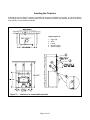
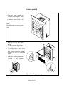
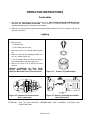
1
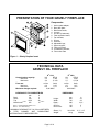
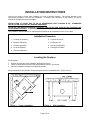
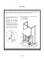
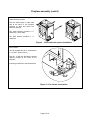
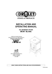
INSTALLATION AND
OPERATION MANUAL
OILBURNING FIREPLACE INSERT
GRIZZLY
Verified and tested following
CAN/CSA B140.3 and UL 896 standards by:
Intertek Testing Services
Fabricated by:
1700 Léon-Harmel
Québec, (Québec)
G1N 4R9
READ THESE INSTRUCTIONS AND SAVE FOR REFERENCE.
990826/45080A
TABLE OF CONTENTS
Table of illustrations ................................................................................................................................................ 1
Presentation of your grizzly fireplace ...................................................................................................................... 2
Technical data ......................................................................................................................................................... 2
Installation instructions ............................................................................................................................................ 3
Installation procedure.......................................................................................................................................... 3
Locating the fireplace.......................................................................................................................................... 3
Clearances .......................................................................................................................................................... 4
Fireplace assembly ............................................................................................................................................. 5
Leveling the fireplace .......................................................................................................................................... 7
Chimney installation............................................................................................................................................ 8
Connecting fireplace to oil tank......................................................................................................................... 10
Preliminary test ................................................................................................................................................. 11
Adjustment of the draught................................................................................................................................. 11
Inserting the fireplace........................................................................................................................................ 13
Facing ............................................................................................................................................................... 14
Operation instructions ........................................................................................................................................... 16
Combustible ...................................................................................................................................................... 16
Lighting.............................................................................................................................................................. 16
Changing intensity ............................................................................................................................................ 17
Turning the stove off ......................................................................................................................................... 17
Maintenance .......................................................................................................................................................... 18
Troubleshooting guide........................................................................................................................................... 19
Spare parts ............................................................................................................................................................ 21
W a r r a n t y ......................................................................................................................................................... 23
TABLE OF ILLUSTRATIONS
Figure 1 :
Figure 2 :
Figure 3 :
Figure 4 :
Figure 5 :
Figure 6 :
Figure 7 :
Figure 8 :
Figure 9 :
Figure 10 :
Figure 11 :
Figure 12 :
Figure 13 :
Figure 14 :
Figure 15 :
Figure 16 :
Figure 17 :
Figure 18 :
Figure 19 :
Figure 20 :
Figure 21 :
Figure 22 :
Figure 23 :
Figure 24 :
Figure 25 :
Figure 26 :
Figure 27 :
Grizzly fireplace insert ....................................................................................................................... 2
Corner installation.............................................................................................................................. 3
Wall installation.................................................................................................................................. 3
Minimum clearances to combustible materials.................................................................................. 4
Carburetor assembly ......................................................................................................................... 5
Hook up of the copper oil supply pipe ............................................................................................... 5
Insulating wool installation................................................................................................................. 5
Top spacer supports installation........................................................................................................ 5
Sides and back spacers installation .................................................................................................. 6
Fan electric connections.................................................................................................................... 6
Levelling the burner ........................................................................................................................... 7
Direct installation ............................................................................................................................... 8
Inside deviation installation................................................................................................................ 8
Exterior deviation installation............................................................................................................. 8
Minimum chimney height................................................................................................................... 9
Chimney clearances. ......................................................................................................................... 9
Fireplace and oil tank connection .................................................................................................... 10
Draught test ..................................................................................................................................... 11
Draught Regulator ........................................................................................................................... 12
Regulator adjustment ...................................................................................................................... 12
Clearances to combustible materials .............................................................................................. 13
Fireplace facing ............................................................................................................................... 15
Burner, ring and catalyst.................................................................................................................. 16
Constant level flow control valve (carburetor) ................................................................................. 16
Arming / dearming flow control valve (carburetor)........................................................................... 16
Cleaning tee..................................................................................................................................... 18
Grizzly exploded view, spare parts list ............................................................................................ 22
Page 1 of 23
PRESENTATION OF YOUR GRIZZLY FIREPLACE
Components:
1.
2.
3.
4.
5.
6.
7.
8.
9.
10.
11.
12.
13.
14.
Anchor plate adaptor;
Burst disc plate;
Blue flame burner;
Louvers;
Oil valve (Carburetor);
Flow regulation button;
Fan rheostat;
Oil pan;
Structure;
Adjustable legs;
Spacer support;
Facing surround;
Combustion chamber;
Flue outlet. Plate
Figure 1 : Grizzly fireplace insert
TECHNICAL DATA
GRIZZLY OIL FIREPLACE
Output heating capacity:
Minimum:
Maximum:
Flow rate :
Minimum:
Maximum:
Minimum draught required:
NO 1 OIL
kW
BTU/h
2,2
7 350
4,4
15 100
cc/min
litre/h
6,0
0,36
12,0
0,72
0,06 INWC
CLEARANCES TO COMBUSTIBLES
mm
in
Back
50
2
Sides
100
4
Top
1220
48
note 1
note 2
255
10
Mantel shelf
NO 2 OIL
kW
BTU/h
1,6
5 550
3,7
12 700
cc/min
litre/h
4,5
0,27
10,0
0,60
0,06 INWC
DIMENSIONS
Note 1 : maximum depth allowed : 8 in.
Note 2 : 10 in above facing.
A MINIMUM CLEARANCE OF 2 in (50 mm) BETWEEN
(A
TYPE)
CHIMNEY
AND
COMBUSTIBLE
MATERIALS HAS TO BE RESPECTED.
Height :
Width :
Depth :
Ø of flue :
Ø of burner :
mm
825
740
480
130
180
in
32
29
19 ½
5
7
Glass ( 3 ) :
Weight :
144 x 264
91 kg
6 ½’’ x 12’’
200 lbs
Page 2 of 23
INSTALLATION INSTRUCTIONS
Here are the steps to follow while installing your new oil burning fireplace. Pay special attention to the
instructions proposed to you such as clearances. In following the instructions of this manual, you will be
assured of a simple and secure installation.
INSTALLATION IN Canada HAS TO BE IN ACCORDANCE WITH CAN/CSA B-139 : STANDARDS
INSTALLATION CODE FOR OIL-BURNING EQUIPMENT.
IN THE U.S. THE NFPA 31 STANDARD NATIONAL FIRE PROTECTION ASSOCIATION STANDARD FOR
OIL-BURNING EQUIPMENT IS TO APPLY.
The installation shall be made by a qualified person member of the corporation in force in your area.
Installation Procedure
1. Locating the fireplace;
6. Connect the oil line;
2. Respect clearances;
7. Preliminary test;
3. Fireplace assembly;
8. Inserting the fireplace;
4. Level the fireplace;
9. Framing the fireplace.
5. Chimney installation;
Locating the fireplace
Some advices :
•
•
•
Choose the room where the installation will benefit everyone;
Favour a central area so that the heat will spread-out evenly in your home;
Chimney installation should be as straight as possible.
Many configurations are possible, the most frequent ones are illustrated bellow. (Figure 2 and 3)
Figure 2 : Corner installation
Figure 3 : Wall installation
Page 3 of 23
Clearances
Refer to technical data of your fireplace on page 2, in order to know its technical and physical characteristics.
Respect required clearances to combustible materials while installing your fireplace. These clearances have
been verified and approved according to CAN/CSA B 140.3 and UL 896 standards.
•
Also respect required clearances of
the (A Type) chimney that you are
installing;
•
For this, see your local dealer to
know what are the clearance
specifications
of
the
chimney
manufacturer that you are using;
•
Don’t forget that the wooden parts of
the frame have to be 2 inches or
more from the factory built chimney;
•
The opening in the frame should be
36 3/4’’ in width by 35 3/4’’ in height.
Following are the clearances to combustible materials:
2’’ Back of fireplace;
4’’ Sides of fireplace;
48’’ Above fireplace.
Figure 4 : Minimum clearances to combustible materials
Page 4 of 23
Fireplace Assembly
For the assembly of your fireplace, you have received with this manual, all the hardware that you need. See
bellow, the list of what should be included.
16 screws no 8 x 5/8’’ to fix spacer supports (stand off);
2 bolts ¼ -20 x ¾’’ to assemble carburetor support on the right side of structure;
2 spacers of 2’’ for the back of the structure;
2 spacers of 4’’ for the sides of the structure;
2 spacer supports of 8’’ for the top of the structure;
3 wire connecters for the assembly of fan rheostat to 110 Volts inlet wire;
Carburetor oil pan.
Carburetor
Install the flow-regulating valve on the right side of
the structure. Fasten the valve support plate with
the bolts provided for this purpose. (Figure 5).
Figure 5 : Carburetor assembly
Oil supply pipe
The copper oil supply pipe has
to be hooked up between the
valve’s outlet and the burner’s
inlet. Use an
7/16’’ key.
(Figure 6).
Figure 6 : Hook up of the copper oil supply pipe
Insulating wool
Top spacer supports
• Remove the chimney trap;
• Install the anchor plate and
the first section of (A type)
factory built chimney of the
brand of your choice;
• The insulating wool has to be
placed on top of the structure.
The top should be completely
covered.
The supports have to be
screwed into the drilled
holes (4 each side) on top
of the fireplace structure.
Figure 7 : Insulating wool installation
Figure 8 : Top spacer supports installation
In order to easily locate the
holes under the wool
blanket, use a 2’’ finishing
nail to find holes.
Page 5 of 23
Fireplace assembly (cont’d)
Sides and back spacers
Use the drilled holes on each side
and at the back of the fireplace
structure to align and screw into
place the spacers;
The sides spacers provides a 4’’
clearance; (1 each side)
The back spacers provides a
clearance.
2’’
Figure 9 : Sides and back spacers installation
Fan rheostat
The fan rheostat has to be connected to
a 110 VAC electric source;
Run the 14 GA wire through the square
opening located at the back of the
structure;
Connect ground wire to the electrical box.
Figure 10 : Fan electric connections
Page 6 of 23
Leveling the fireplace
Figure 11 : Levelling the burner
• Now that your fireplace is installed into place, you have to level the burner.
• Put the level in the middle of the burner parallel to the door. (See figure 11-a). Screw or unscrew the
adjustable legs until perfect level has been reached. Use a 7/16’’ (10 mm) key.
• Then put the level in the middle of the burner so that it is parallel to the sides (See figure 11-b). Screw
or unscrew the adjustable legs until perfect level has been reached. Use a 7/16’’ (10 mm) key.
IMPORTANT :
IT IS VERY IMPORTANT TO LEVEL THE BURNER TO ALLOW A PROPER OIL VAPOR
DISTRIBUTION THROUGHT THE RING AND THE CATALYTIC CONVERTER.
Page 7 of 23
Chimney installation
• ONLY (‘’A’’ TYPE) FACTORY BUILT CHIMNEY CAN BE USED for the installation of your GRIZZLY
fireplace. Use only 30 O or 45O elbows. NO 90O ELBOWS ARE ALLOWED.
• The use of BLACK PIPE CONNECTORS (SINGLE OR DOUBLE WALL PIPES) IS STRICTLY
PROHIBITED.
• Many configurations are possible, the most frequent ones are illustrated in figures 12, 13, and 14.
• Respect clearances indicated in table 1. These clearances have been tested and verified in the
course of certification and homologation sessions. Also respect factory built chimney required
clearances. See your dealer to know the specifications of the chimney manufacturer.
Figure 12 : Direct installation
Figure 13 : Inside deviation installation
• NOTE: It is essential to ensure yourself that
the room where the fireplace is located
sufficiently ventilated to provide an adequate
air supply.
• If your home is well insulated, it is possible that
you will have to install an fresh air intake
directly from outside and routed to the unit.
• Drolet Stoves & Fireplaces do not recommend
that you connect a factory built chimney to a
masonry chimney.
Figure 14 : Exterior deviation installation
THE BURNING OF ONE LITRE OF FUEL (OIL) REQUIRES APPROXIMATLY 30 m3
OF AIR AND WILL PRODUCE ABOUT 0,8 kg OF WATER VAPOR AND 9 m3 OF
CARBONE DIOXIDE AND ATMOSPHERIC NITROGEN. A SOURCE OF AIR FROM
THE OUTSIDE IS NEEDED TO REPLACE COMBUSTION AIR.
Page 8 of 23
Chimney installation (cont’d)
• DROLET STOVES & FIREPLACES requires the use of an (A TYPE) factory built chimney having a
constant 5’’diameter. Using a larger flue tends to make combustion gas expand and cools them off
witch have for result of lowering the draught effects. Gas expansion reduces the speed of the draught
and have the same effects.
• Low gas temperature will tend to condense and freeze or leak in your chimney.
• Refer to technical data in (table 1) in order to know the required minimum draught needed for your
fireplace. Follow this specification for proper operation.
• The chimney has to reach a minimum of 15’ high. It has to extend not less than 3’ above the point it
exits the roof and 2’ higher than any roof, building or other obstacles within a horizontal distance of 10’.
• CHIMNEY MINIMUM HEIGHT:
Chimney height must not be less than 15’.
(4.6 m).
Figure 15 : Minimum chimney height.
• CLEARANCES WITH ROOF SUMMIT AND
BUILDING NEARBY :
The chimney flue shall extend at least 2’
(0.6m) above the highest roof surface or
structure within 10’ (3 m) horizontally of the
chimney.
Figure 16 : Chimney clearances.
• CLEARANCE FROM ROOFING INTERSECTION :
The chimney flue shall extend at least 3’ (0,9 m) above the highest point at witch it comes in contact
with the roof.
YOUR APPLIANCE SHALL BE CONNECTED TO A CHIMNEY HAVING SUFFICIENT DRAUGHT AT ALL
TIME TO ASSURE SAFE AND PROPER OPERATION OF THE BURNER.
Page 9 of 23
Connecting fireplace to oil tank
• Make sure that the tank outlet is 12" (305 mm) higher than the inlet of the carburetor. (Gravity fed)
• Use only copper piping to connect tank to stove.
• Make sure that there is a small slope on the connection from the tank toward the stove.
• A 3" (75 mm) down slope is needed on the tank itself, from the outlet towards the other end of the
tank.
• When the tank is installed outdoors, it is preferable to use oil #1, to avoid viscosity problems.
NOTE :
THE BAROMETRIC TANK SHALL BE LOCATED SO THAT THE TANK WILL NOT BE
EXPOSED TO THE DIRECT RAYS OF THE SUN OR BE ADJACENT TO ANY SOURCE OF
INTENSE HEAT.
Figure 17 : Fireplace and oil tank connection
Page 10 of 23
Preliminary test
Before inserting the fireplace, it is suggested to verify the items listed below and correct if necessary;
•
•
•
•
•
Leaks on copper connections; inlet and outlet of the valve as well as the inlet of the burner;
The chimney is properly in place and well secured with approved parts;
The burner has been levelled;
The fireplace is permanently attached to hearth;
Enough draught is available and has been adjusted according to the following procedures.
Adjustment of the draught
• Your stove operates with natural draught, created by the ascension of combustion gases in the
chimney. This movement creates a siphon effect in the stove and forces ambient air to go in the burner
by the holes in its surround. These orifices let air in for combustion.
• For the unit to function properly, it is essential to check the quality of the draught using a draught
gauge. The draught is usually measured in inches of water column.
• Check the minimum draught required of the unit on page 1. The draught mentioned has to be reached
rapidly at a minimum settling (position #1).
• Depending on the model, the draught can be taken by the orifice on the cooking surface. The measure
can also be taken by the orifice on the draught regulator usually plugged by a rubber cap. The orifice
on the cooking surface is still the best area.
IMPORTANT : ALWAYS MEASURE THE DRAUGHT WITH ALL VENTILATION EQUIPMENT
INSTALLED IN THE HOUSE (RANGE HOOD, BATHROOM FAN, AIR EXCHANGER, DRYER, ETC IN
OPERATION.)
ref. : standard CAN/CSA B-139 art. 4.1.5.
Measuring the draught :
• For a proper operation of the fireplace, it is
essential to check the chimney draught
with a draught gauge.
Since natural
draught is low, inches or millimetres of
Water Column are used for the draught
measurements.
• Chimney’s minimum draught required is
0,06’’ of W.C. Draught should be reached
rapidly at the minimum flow setting,
(position «1»).
• Measure the draught by using the hole
made in the burst disc plate designed for
this purpose. (see figure 18).
Figure 18 :
Page 11 of 23
Draught test
Preliminary Test (cont’d)
Draught regulator :
• An excessive draught is as bad as a draught
to low.
• The regulator controls the draught when it is
excessive (in high winds for example).
•
If the draught exceeds 0.08 in of water
column, you will have to adjust the regulator
Figure 19 : Draught Regulator
Adjusting the draught :
• To adjust the draught you have to screw or
unscrew the court weight on the regulator.
Regulator open lowers the draught regulator
closed increases the draught.
Figure 20 : Regulator adjustment
THE ONLY RIGHT WAY OF MEASURING THE DRAUGHT IS TO USE A DRAUGHT GAUGE THAT
GIVES READING IN INCHES OF WATER COLUMN. ALL OTHER METHOD (CANDLE, MATCHES,
ETC.) ARE UNRELIABLE.
INSTALLATION OF YOUR STOVE HAS TO BE IN ACCORDANCE WITH CAN/CSA B-139
INSTALLATION CODE FOR OIL-BURNING EQUIPMENT IN CANADA AND STANDARD NFPA 31
NATIONAL FIRE PROTECTION ASSOCIATION STANDARD FOR OIL-BURNING EQUIPMENT IN THE
U.S..
NOTE :
THE INSTALLATION SHALL BE MADE BY A QUALIFIED PERSON MEMBER OF THE CORPORATION
IN FORCE IN YOUR AREA.
Page 12 of 23
Inserting the Fireplace
Now that the unit is in place, the burner is levelled and all previous verifications are made. It is time to build the
surrounding frame and walls. Always respect minimum clearances between, the fireplace as well as the factory
built chimney, and combustible materials.
Legend, figure 21
1.
2.
3.
4.
5.
Figure 21 : Clearances to combustible materials
Page 13 of 23
Gyps wall;
Shelf;
Facing;
Wooden frame;
Spacer support
Facing
1. Assemble the (3) parts of the
facing using the (4) nuts and
bolts received in the hardware
package.
2. Place the assembled facing
on the front part of the
fireplace :
Align bottom of the facing
with the bottom of the
fireplace structure;
Align the flow regulating rod
with the hole on the right
side of the facing;
Insert the inner edges of the
facing in the clips located on
the
outside
of
the
combustion chamber.
Page 14 of 23
Facing (cont’d)
3. Push the facing towards the
structure of the fireplace. (Push
in aligned with clips).
Install the control knob on the
flow regulating rod.
NOTE :
The facing must lean evenly on the
fireplace structure and finished front
wall.
4. Hook up the top and bottom
louvers:
The top louver sits on (4) hooks.
The bottom louver slides in (2) pins.
The bottom louver is used as an
access panel. Tip it towards you to
have access to the fan rheostat,
cleaning tee and the carburetor
(valve).
5. Install the small polished brass
handle using (1) bolt and (1) nut
provided
in
the
hardware
package.
Figure 22 : Fireplace facing
Page 15 of 23
OPERATION INSTRUCTIONS
Combustible
• Your stove has been designed to work with oil #1 or #2. DO NOT USE GASOLINE, CRANKCASE OIL
OR ANY OIL CONTAINING GASOLINE. Drolet Stoves & Fireplaces declines all responsibility
regarding damage cause by using other combustibles.
• Make sure to use oil without impurities which may plug filters and valve’s orifice. Impurities only give an
improper combustion.
Lighting
BEFORE LIGHTING
• make sure that :
The tank is full;
The isolating valve is open;
• See that the ring is in the right position.(figure
23).
• Make sure that the flow regulating handle is in
the « 0 » position (figure 24).
• If it’s not already done, arm down the valve’s
lever located behind the stove (figure 25).
• Wait for the valve to fill up and let the level
stabilize.
BEFORE ATTEMPTING TO LIGHT YOUR
STOVE, MAKE SURE THAT THE FLOW
REGULATING HANDLE IS IN THE 0 POSITION.
Figure 23 :
Figure 24 : Constant level flow control
valve (carburetor)
Figure 25 : Arming / dearming flow control
valve (carburetor)..
ATTENTION:
Burner, ring and catalyst
DUE TO HIGH SURFACE TEMPERATURE, KEEP CHILDREN, CLOTHING AND
FURNITURE AWAY
Page 16 of 23
Lighting (cont’d)
• Place the flow regulating handle on the "1" position, as soon as the oil enters the burner
return to "0" position.
• Open the door and pore into the burner 2 to 3 once (75 ml) of lighting gel or wood alcohol.
NOTE : USE OF LIGHTING GEL IS BETTER OF A SAFE IGNITION.
• With a long wood match, ignite carefully and close the door.
• After a couple of minutes (before alcohol goes out) the burner and the chimney are hot, place
the flow regulator handle on "1" position.
Note : Do not leave matches or other materials in the burner in order to keep it
clean. It allows a better combustion.
IF YOU MISS THE STOVE’S LIGHTING, ALWAYS WAIT FOR THE
BURNER TO COOL DOWN TO ROOM TEMPERATURE BEFORE USING
BURNING ALCOHOL AGAIN.
IF, FURTHER TO SOME MISOPERATION, THE BURNER IS FILLED
WITH IMPORTANT QUANTITIES OF OIL, ALL OF THE OIL MUST FIRST
BE REMOVED BEFORE LIGHTING THE STOVE AGAIN.
Changing intensity
• Always wait 10 minutes minimum before increasing the flow (between each position). This allows
flamme to stabilize and avoid suiting up.
• No waiting is needed to decrease the flow.
Turning the stove off
• Set the flow regulating handle to position ‘’0’’.
• If you plan to keep the stove off for a long while, it is recommended to disarm the valve’s lever and
close the tap on the pipe between the stove and your oil tank.
ALWAYS KEEP THE VALVE SHUT OFF WHEN THE BURNER IS NOT OPERATING
Page 17 of 23
MAINTENANCE
ONCE A WEEK :
• Clean the oil inlet tube of the burner with the
cleaning tee :
Push in the rod of the cleaning tee while
turning it;
move back and forth operation 2 or 3
times;
Pull it back into place to finish the
operation.
Figure 26 : Cleaning tee
WHEN YOUR STOVE IS RUNNING, ALWAYS KEEP THE CLEANING TEE LEVER PULLED BACK
INTO PLACE.
ONCE A MONTH OR TWO :
• Clean with a metallic brush :
• The burner’s shell;
• The burner’s rings;
• The burner’s catalyst (in blue flame model).
AT THE BEGINNING OF EACH HEATING SEASON :
• Clean the valve and tank filters;
• Inspect the smoke box through the opening of the rear flue outlet;
• Clean the chimney and flue pipe.
MAKE SURE THAT ALL HAND VALVES ARE CLOSED BEFORE CLEANING PROCEDURES.
WHEN NEEDED :
• Clean the glass door;
• The glasses have to be cleaned only when the stove is cold. Use commercial product for this purpose,
or a water and vinegar solution.
Page 18 of 23
TROUBLESHOOTING GUIDE
PROBLEMS
CAUSES
SOLUTION
ON POSITION 6 (MAXIMUM)
THE FLAME IS LONG AND
SMOKY, THERE IS SUIT
BUILD UPON THE GLASS.
Position 6 was reached too
quickly.
1. Set flow regulating handle to
position 1;
2. wait for combustion to
stabilize;
3. Progressively increase flow
to desired position.
NOTE :
SEE
LIGHTING
PROCEDURES.
Maximum flow is too high.
1. Set flow to a lower position;
2. Call a qualified technician to
adjust the valve.
Cleaning tee and/or burner are
dirty.
1. Activate
cleaning
tee
according to procedures;
2. Schedule at the next shut off
to clean the burner.
Orifice of plunger is partially
plugged.
1. Progressively increase flow
to position 6;
2. Push in many consecutive
times on the thermostatic
regulator bottom to remove
dirt form the orifice.
ON POSITION 1 (MINIMUM)
THE FLAME PRODUCES
SMOKE AND SUITS THE
GLASS.
NOTE : If the problem persist,
you may have to remove and
clean out the valve with alcohol.
Call
your
specialized
technician.
ON POSITION 1 (MINIMUM)
THE FLAME PRODUCES
SMOKE AND SUITS THE
GLASS.
Flow is to low.
Page 19 of 23
1. Slightly increase the flow
regulating handle;
2. Call a specialized technician.
TROUBLESHOOTING GUIDE (CONT’D)
PROBLEMS
THE FLAME PRODUCES
SMOKE, IN ANY POSITION.
FLAME GOES OUT BY
ITSELF.
THE STOVE MAKES NOISE,
GOES OUT AND LIGHT UP
AGAIN.
CAUSES
Door gasket
properly.
is
not
SOLUTION
selling
1. Tighten door by turning
counter clockwise the door
handle;
2. Check if gasket needs to be
changed.
The burner orifices are plugged
up.
1. Clean the burner with a
metallic brush.
Draught is too low.
1. Make it checked
technician.
Oil level in the tank is too low.
1. Fill up the tank.
Air pocket is stocked in the oil
line.
1. Call a technician to drain the
line;
2. Make sure that the oil line
has an adequate slope
towards the tank.
Oil #2 is used in exterior tank.
1. Use only oil #1 when tank is
installed outside.
Partial or total obstruction by
impurities in oil line or filters.
1. Check filters on tank and
valve;
2. Ask a technician if the
cleanness of the tank and
line is OK.
The stove has been lit while
excess of oil was in the burner.
1. Position the flow regulating
handle to ‘’0’’;
2. Let the stove cool down;
3. Clean
the
burner
if
necessary.
Note : Never light the stove
when the burner is full of oil.
Sponge the oil out before
lighting.
Page 20 of 23
by
a
SPARE PARTS
After years of use, if you need to replace some parts, please contact your SUPPLIER or one of our Drolet
approved DEALERS.
• Give him product data as displayed in your warranty voucher or on your appliance’s name plate at the
rear. Keep the warranty voucher even after its EXPIRY date.
• Our dealers are in possession of all spare parts nomenclatures and technical data about our products,
and will provide you with the spare parts you need and any maintenance intervention within the scope of
their professional competence.
NO.
1
2
3
4
5
6
7
8
9
10
11
12
13
14
15
16
17
18
19
20
21
22
23
24
25
26
27
28
29
30
31
32
33
DESCRIPTION
Handle gold plated
Handle rod
Hinge
Cast iron door
Window gasket 1/16’’ x 3/8’’
Borosilicate glass plate (3)
Glass moulding (lower)
Glass moulding (upper)
Door gasket ½’’
Louver door
Louver
Facing
Heat deflector
Cleaning tee
Burner blue flame 7’’
Burning ring
Catalyst
Fan
Fan deflector
Fan support
Chimney trap
Valve support
Pan (carburetor)
Fan rheostat
Rheostat front plate
Rheostat
90O male outlet elbow
Oil feeding line
Draught regulator
Burner pan
Rheostat button
Valve control rod assembly
Valve control gear
Page 21 of 23
SPARE PARTS (CONT’D)
Figure 27 : Grizzly exploded view, spare parts list
Page 22 of 23
WARRANTY
The Drolet Stoves & Fireplaces warranty applies to the original buyer only. This warranty may not be
transferred to a second person and becomes effective on the date of purchase. Proof of purchase is
necessary to validate the warranty and to establish the warranty coverage period.
The warranty is conditional to normal residential use of the product. Any use other than that for which
the product was intended will invalidate the warranty. The warranty covers repairs and (or) parts
replacement under the terms established by Drolet Stoves & Fireplaces.
PRODUCT
Wood (except Hunter)
GAS
OIL
GODIN
EXTERIOR FIREPLACE
HUNTER
FIREBOX
5 years
5 years
5 years
5 years
1 year
N/A
PAINT
1 year
1 year
1 year
1 year
N/A
N/A
COMPONENT
1 year
1 year
1 year
1 year
N/A
N/A
FIREBOX AND PAINT
The warranty covers manufacturer defects and materials.
COMPONENTS
The following components are covered by the one-year warranty as follows:
• Woodstoves :
Ceramic glass, refractory bricks, gasket, blower, thermodisc and rheostat.
• Gas units :
Ceramic glass, valve, burner, piezo ignitor, pilot, blower and thermodisc.
• Drolet Oil Stoves :
Burner, burner rings, cleaning tee and electrical components.
EXCLUSIONS
This warranty will not cover labour costs or any costs related to damages caused by faulty installation, repairs,
abusive use or wrong usage of the product, either by a contractor, a service representative or the buyer himself.
All defects or damages caused by the use of parts other than Drolet Stoves & Fireplaces original parts
automatically cancels the warranty.
Drolet Stoves & Fireplaces cannot be held responsible of any claims whatsoever, other than the replacement
of the parts themselves.
How can we resolve your claims ?
Drolet Stoves & Fireplaces will honour F.O.B. plant (collect) parts replacement for defective parts.
Before sending back products or components to our office, you must be given an authorization number
from our representative or your dealer.
Page 23 of 23