1
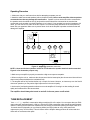
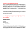
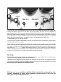
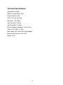
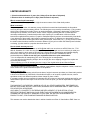
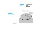
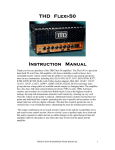
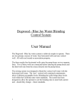
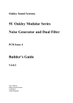
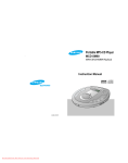
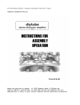
one step ahead
a brand of ENG Vista, Inc.
m o d el i 3 4
Integrated Tube Amplifier
User’s Manual
http://www.vista-audio.com/
1
Rev. 4
Dear Customer
We at ENG Vista want to take this opportunity to thank you for purchasing the model i34
Integrated Tube Amplifier. The people that stand behind your amplifier draw on more than
a decade of professional electronics design and manufacturing experience. We are
committed to providing our customers with the high quality sound at affordable prices. We
have achieved this goal through modern design, quality parts, expert components sourcing
and efficient manufacturing. We are confident that your amplifier will give you many years
of listening pleasure as a part of your audio system.
Before using this amplifier, please take the time to carefully read and understand the safety
instructions and operating procedures. Becoming familiar with all details about your
amplifier will ensure safe usage and reliable operation. Especially important is the section
on tube layout which gives information on tube replacement.
The effort you invest now will be well rewarded as the time goes by.
THANK YOU!
ENG Vista, Inc.
Table of Contents
Section
Page No.
Safety Precautions
Getting Started
About Your Amplifier
Construction and Testing
Packaging/Unpacking
Accessories
Preparation for Use
Operating Procedures
Controls and Their Functions
Vacuum Tube Layout:
Tube Replacement
Biasing Output Tubes
Servicing
Technical Specifications
3, 4
5
5
5, 6
6
6
6
6
6
7
8
9
10
2
SAFETY PRECAUTIONS
IMPORTANT SAFEGUARDS
PLEASE READ CAREFULLY ALL THE
FOLLOWING IMPORTANT SAFEGUARDS THAT
ARE APPLICABLE TO YOUR EQUIPMENT
CAUTION!
TO REDUCE THE RISK OF ELECTRIC SHOCK, DO NOT REMOVE SCREWS. NO USER
SERVICEABLE PARTS INSIDE. REFER SERVICING TO QUALIFIED SERVICE
PERSONNEL.
SAFETY
1) Read the User’s Manual and refer to it frequently during use of this product - All the safety
and operating instructions should be read before the product is operated.
2) Retain the User’s Manual - The safety and operating instructions should be retained for future
reference.
3) Follow Instructions - All operating and instructions for use should be closely followed.
4) Power Sources - This product should be operated using only the type of power source
indicated on the marking label. If you are not sure of the type of power supply in your home, consult
your product dealer or local power company.
5) Grounding - This product is equipped with a three prong IEC connector. Always use power cord
with adequate wire cross section and an electrical outlet that is grounded. If you do not know whether
the outlet is grounded, consult your electrician or local power company.
6) Power Cord Protection – Power supply cords should be routed so that they are not likely to be
walked on or pinched. Pay particular attention to cords at plugs, convenience receptacles and
where they exit from the product. Always use power cords with adequate current ratings and
safety certifications (UL, CE, TÜV, CSA, etc.)
7) Fuses - For continued protection against fire hazard, replace fuses with the same type and rating of
the fuses specified. When changing fuses, completely unplug the AC cord from the wall outlet.
8) Tubes - During operation the tubes get very hot. Do not touch the tubes since this may result in
a severe burn. Allow at least 10 minutes after removing power for tubes to cool down before
touching them.
9) Turn-off when not using - Turn off the unit as soon as you stop actively using it. Unplug the
power supply from the wall during a lightning storm or when the product is to be left unattended and
unused for longer periods of time.
3
ENVIRONMENT
1) Water and Moisture - Do not use this product near water - i.e. near a bathtub, ash bowl, kitchen sink
or laundry tub; in a wet basement; or near a swimming pool or the like. Damp basements should be
avoided.
2) Heat - The product should be situated away from heat sources such as radiators, heat registers,
stoves or other appliances that produce heat. Also avoid putting the unit in the direct rays of the sun.
3) For indoor use only.
PLACEMENT
1) Accessibility - It is normal for a vacuum tube power amplifier to run warm if used for prolonged periods.
Tubes are very hot when operating and should not be touched for at least ten minutes after the unit is turned
off to prevent burns. Always place your amplifier away from children and pets to prevent burns.
2) Ventilation - This product should not be placed in a built-in installation or rack unless proper
ventilation is provided or the manufacturer's instructions have been followed. Never place anything
on top your amplifier that could obstruct the airflow and cause the electron tubes to overheat and damage
the amplifier. Do not place your amplifier in a closed bookcase; overheating could occur. Ensure that
there is at least 8” (200mm) of open space above the amplifier.
2) Surface - Place the unit on a flat level surface. Care should be taken to prevent objects from falling and
liquids from spilling into the unit. Do not subject the unit to excessive smoke, dust, vibration or shock.
MAINTENANCE
1) Cleaning - Unplug this product from the wall outlet before cleaning. Do not use liquid cleaners or
aerosol cleaners. Use a dry cloth for cleaning. Do not use any type of abrasive pad, scouring
powder or solvent such as alcohol or benzene.
2) Tube replacement – Electron tubes have their life in the 1000-2000 hrs range. We strongly recommend
replacing the output tubes at 12-18 months interval (depending on your listening habits) and signal tubes
at every other power tube replacement (after 24-36 months). This will ensure that the amplifier always
performs at its best and tube failure will not overstress other parts.
3) Biasing the amplifier - The model i34 amplifier uses tubes in fixed bias configuration. The amplifier is
delivered with adjusted bias. Bias adjustment is required only when replacing the original tubes. Matched
tubes should be used in each channel. They are available from multiple vendors as well as directly from
Vista Audio.
4) Socket contacts – tube pins and socket contacts are subject to oxidation. If the amplifier is not used
for several days at a time, the oxidation may cause loss of contact and it may be necessary to reinsert
tubes to restore the operation.
SERVICE
1) Replacement Parts - When replacement parts are required, be sure that the service technician
uses replacement parts specified by the manufacturer or parts with the same characteristics as the original
part. Unauthorized substitutions may result in fire, electric shock or other hazards.
2) Tube Replacement/Rolling - Should it become necessary to replace your tubes, remove the
AC power plug from the wall and allow thirty minutes for the high voltage capacitors to discharge.
Follow instructions outlined in this manual. Tube rolling (frequent replacement for experimenting
purposes) is not recommended – the tube sockets are sensitive mechanical parts and frequent
insertions will cause premature failure and loss of contact, which may result in amplifier damages.
3) Modifications – Modifications to the amplifier are strongly discouraged. The unit was designed
by experienced engineers and tested for safe and reliable operation. Any modification may pose a
safety problem and result in reduced lifetime of the product. Removing cover will void warranty.
4
Getting Started - About Your Amplifier
Your model i34 amplifier was designed to provide a significant value based on a high performance to price
ratio that will exceed the sonic quality of good solid state amplifiers with its musical accuracy.
The model i34 uses 2 sets of matched pairs or one matched quad (total of 4) of E34L power output tubes and
two ECC832 preamp tubes. The model i34 is designed to work in class AB and deliver up to 35W of clean
power. Parts are carefully chosen for the optimum sound quality and the overall circuit layout is maximized for
sonic purity.
Construction and Testing
Like every Vista Audio product, your power amplifier has been carefully crafted by skilled mechanics. To assure
consistent performance, each model i34 amplifier goes through the full battery of electrical tests, extended
burn-in and listening evaluation before being shipped. This time-consuming perfectionist approach in the design
and manufacturing of audio equipment is intended to provide the best in musical satisfaction with lasting value.
Handling Vacuum Tubes
Many people have never had experience handling vacuum tubes. Process is very similar to handling
incandescent light bulbs. As with light bulbs, you should not touch a vacuum tube when it is operating since
you can burn yourself. Similarly, if a tube is dropped on a hard surface it will break. When replacing the tubes
allow sufficient time, minimum 30 minutes, for tubes to cool down and internal capacitors to discharge. Before
you insert a tube you should make certain the unit is disconnected from the AC outlet and that the tube has
cooled down. Inspect the tube for cracks and physical damage. Make sure that the pins are straight. If you need
to straighten the pins, be very careful as it may cause the glass envelope to break, causing the tube to lose the
vacuum and fail as soon as the amplifier is powered on. Carefully align the pins with the socket and gently insert
the tube. Never force a tube into a socket. Should you decide to buy replacement tubes from Vista Audio,
rest assured that they were fully tested before the shipment.
Packaging
Save all the packaging in a dry place. Your amplifier is a precision electronic instrument and should be properly
packaged any time shipment is made. Because of its weight it is highly probable that the unit will be damaged
during shipment if repackaged in a box and packing other than that designed for the unit.
Preparation for Use
Place your amplifier on a flat surface.
model i34 amplifier is delivered with matched quad or two matched pairs of output tubes E34L. The
amplifier comes with adjusted bias and it is important to follow markings on the tube boxes and insert them
into appropriate sockets, according to the drawing below. No biasing is required until you are ready to replace
the output tubes with a new set. Biasing procedure is explained in the chapter about tube replacement.
Before inserting the tubes, inspect them for cracks and physical damage. Make sure that the pins are straight. If
you need to straighten the pins, be very careful as that may cause the glass envelope to break, causing the
tube to lose the vacuum and fail as soon as the amplifier is powered on. Refer to the drawing below to locate
correct location for each tube. Carefully align the pins with the socket and gently insert the tube according to the
drawing below. Never force a tube into a socket.
5
E34L
V1
E34L
E34L
E34L
ECC832
V4
ECC832
V2
V3
V6
V5
model i34
Figure 1: model i34 tube layout
Never use excessive force when inserting the tubes into their socket.
Controls and Their Functions
Front Panel
Selector Switch – The three position selector switch can be used to select the active audio source.
Volume control - This control is used to adjust the output volume level. Turning the control knob clockwise
increases the sound level and turning it counterclockwise decreases the sound level.
Back Panel
Power Switch: Press the power switch to (I) turn the power on. Within 10-20 seconds, as the heaters
reach operating temperature the tubes will begin to glow a soft orange light. Press the power switch to (0)
to turn the unit off. As the heaters cool off, the orange glow will slowly disappear.
It is normal for a vacuum tube equipment to run warm if used for prolonged periods. Tubes are
operating at much higher temperature and should not be touched for at least ten minutes after the unit
is turned off to prevent burns. Always place your amplifier away from children and pets to prevent
burns.
Audio signal connection jacks - Use these jacks to connect the audio interconnects from your source
components to the amplifier.
S p e a k e r t e r m i n a l s - Your amplifier has two output channels, the Right Output and the Left
Output. Each output channel is designed to handle one speaker. Follow the instructions outlined in the
Operating Procedure for the correct speaker connections.
6
Operating Procedure
1. Make sure that you read instructions before attempting to operate your unit.
2. Attach the audio sources and speakers (refer to the picture below). Never run the amplifier without speakers
connected since that may damage the transformers. Speaker’s minus terminal should be connected to
the speaker terminal marked as zero (0) and positive terminal should be connected to the terminal that
corresponds to the speaker’s nominal impedance (4 or 8 ohms). If your speaker has nominal impedance of 6
ohms, you can connect it to either of the two outputs. You should try both and select the one that performs
better with your speakers. Make sure to prevent short circuit at the amplifier’s speaker terminals as that will
damage the amplifier
8 ohms
4 ohms
R ch.
0
4
L ch.
8
ohms
0
4
8
model i34
4 ohms
8 ohms
Figure 2: model i34 speakers connection
NOTE: 4 ohms and 8 ohms speakers cannot be connected to the speaker terminals at the same time!
Figure 2 is for illustration purpose only.
3. Make sure your amplifier is properly connected to a high-current power receptacle.
4. When turning the unit on, make sure the volume control is at its lowest point (the volume control is at minimum
when turned counterclockwise to the mechanical limit).
5. The amplifier will be fully functional after only a couple of minutes. However, as it warms up over the first 30
minutes of operation you may notice slight improvement in the sound quality.
6. At the end of your listening session make sure to turn the amplifier off. Leaving it on does nothing for sound
quality and it reduces life of the vacuum tubes.
The amplifier should always be turned on and off via its own power on-off switch.
TUBE REPLACEMENT
Your model i34 amplifier’s conservative design maximizes life of the tubes. You can expect that your E34L
power tubes will last approximately 1200 hrs, while the ECC832 preamplifier tubes should last approximately
2500 hrs. Lacking the accurate time measurement, we strongly recommend replacing the output tubes at 1218 months interval (depending on your listening habits) and signal tubes at every other power tube
replacement (every 24-36 months). This will ensure that the amplifier always performs at its best and tube
failure will not overstress other parts.
7
Only matched pairs of output tubes should be used for each channel.
Before you start replacement you should make certain that the unit is turned off and disconnected from the AC
outlet and that the tubes have cooled down. Allow sufficient time, minimum 30 minutes, for tubes to cool down
and internal capacitors to discharge. Before inserting a new tube, inspect the tube for cracks and physical
damage. Make sure that the pins are straight. If you need to straighten the pins, be very careful as it may cause
the glass envelope to break, causing the tube to lose the vacuum and fail as soon as the amplifier is powered
on, possibly damaging the amplifier as well. Also, make sure to inspect the tube sockets for cracks and pin
inserts. Carefully align the pins with the socket and gently insert the new tube. Never force a tube into a
socket. Should you decide to buy replacement tubes from Vista Audio, rest assured that they were fully tested
before the shipment.
Once the new tubes are inserted, the biasing procedure must be performed, as explained below.
Only E34L or EL34 power tubes can be used. Regarding preamplifier tubes, the ECC832 tube can be replaced
with 12DW7, 7247 or ECC82 with different effects on sensitivity and sonic performance. No other types of tubes
can be used as they may cause a damage to the amplifier which is not covered by the warranty.
We do not recommend frequent changes of the tubes, as the sockets are sensitive mechanical parts and are
rated for relatively small number of insertions.
Tube rolling (frequent replacement for experimenting purposes) is not recommended – the
tube sockets are sensitive mechanical parts and frequent insertions will cause premature
failure and loss of contact, which may result in amplifier damages. Every replacement of the
tubes has to be followed by the bias adjustment procedure. Only matched pairs should be
used for each channel.
Biasing Output Tubes
Biasing output tubes ensures that the tubes run with optimum operating conditions for maximum life and
performance.
Biasing tools required:
- small flat screwdriver
- voltmeter
Biasing procedure:
1. Once the new output tubes are in, turn the amplifier on and allow 2 minutes for tubes to warm up.
2. Start working on one channel only and measure bias voltage for each individual output tube at the test
points indicated on the picture below (to measure bias voltage connect negative input of your voltmeter to
the turret screws marked GND and positive input to one of the turrets with plastic insulation underneath Vbias 1 through Vbias 4):
8
3. Even though you are using matched tubes, they are likely to have somewhat different bias voltages. By
rotating bias control adjust bias on the tube with higher reading. The bias should be adjusted to
approximately 350mV (0.35V), any value between 340 and 360mV (0.34 to 0.36V) is acceptable. For actual
bias current divide measured voltage by 10 to get current in mA (350mV=35mA). Check the bias reading
on the other tube and it may not be identical, but should not be lower than 290mV (0.29V). If it is, you are
likely to have poorly matched tubes - the amplifier will work, but performance may suffer a bit.
4. Repeat steps 2 and 3 for the other channel.
5. At this point you may allow the amplifier to work for a longer period of time (30 minutes or more) and then
check and readjust bias, if necessary.
Even though you may be tempted to check bias every so often, the practice will not give you meaningful
results - tube bias will depend on the input voltage value and even small variations of the AC line will make
bias voltage drift slightly causing your readings to differ and creating perception that tubes drifted more than
they actually do. model i34 amplifier was designed with this in mind - tubes are run well below their
maximum ratings and normal variations of bias voltage will not affect their life nor performance. Checking
the bias every 200-300 hours of operation is acceptable, although not required.
Servicing
Because of its careful design and high manufacturing standards, your amplifier should normally require
only minimal service to maintain its high level of performance.
CAUTION: Lethal voltages are present inside the amplifier. Do not remove the amplifier’s bottom
cover and do not tamper with components inside the unit even with the power turned off. Servicing
should be left only to authorized and trained personnel.
We thank you for your confidence in Vista-Audio products. Our equipment has been
carefully assembled by highly skilled engineers and technicians. It will give you
many years of top-notch performance.
9
Technical Specifications:
Integrated tube amplifier
Maximum output power: 35W
Class of operation: AB
THD: 0.3% max (1W/1kHz)
Bandwidth: 15Hz-35kHz
Input sensitivity: 0.6Vrms
Input impedance: 50 kohm
Output (speaker) impedance: 4 and 8 ohms
Tubes: 2 x ECC832, 4 x E34L
Input Voltage: 120V, 60Hz (230V, 50Hz available)
Maximum input current: 2A at 120V
Weight: 24 lbs
10
LIMITED WARRANTY
1. Chassis and transformers: 2 years plus 10 days (from the date of shipment)
2. Electron tubes: 6 months plus 10 days (from the date of shipment)
Who is covered by this warranty?
Your Vista-Audio warranty protects the original consumer owner of this Vista-Audio product.
What is covered?
Except as specified below, this warranty covers all defects in material and workmanship in this product
occurring during the above warranty periods. The following are not covered by the warranty: (1) Any product
which is not purchased from Audio-Vista or an authorized dealer; (2) damage, deterioration or malfunction
resulting from a) accident, act of nature, abuse, misuse, neglect (including the lack of reasonable and
necessary maintenance), unauthorized product repair, opening of or modification or failure to follow
instructions supplied with the product, b) repair or attempted repair by anyone not authorized by Vista-Audio,
c) any shipment of the product (claim must be presented to carrier); (3) damage to or deterioration of any
accessory or decorative surface (decorative wood, paint defects, mirror finish, etc.); (4) any product on which
the serial number has been modified, removed or defaced; (5) any unit on which the warranty seal is broken
or missing; (6) units used for a purpose other than home use.
How to obtain warranty service?
If your unit ever needs service contact us at [email protected] or write to us at ENG Vista, Inc., 77-21
86th St, Glendale, NY 11385. We may direct you to an authorized repair service or ask that you send your
unit to us for repair in which case we will send you a Service Return Authorization and detailed shipping
instructions. Either way you will need to present the original bill of sale to establish the date of
purchase/shipment. Please do not ship your equipment without our prior authorization.
- You are responsible for transporting your unit or arranging for its transportation.
- You must pay the initial shipping charges, but we will pay the return shipping charges if the repairs are
covered by the warranty.
- When returning your unit for warranty service, a copy of the original sales slip and Service Return
Authorization number must be attached.
You should include the following: your name, address, email address, daytime telephone number, model and
serial number of the product and a description of the problem.
What we will pay for?
If during the applicable warranty period from the date of original consumer purchase your Vista-Audio product
is found to be defective by Vista-Audio, Vista-Audio will repair, or at its option, replace with new, used or
equivalent model, such defective product without charge for parts or labor.
If necessary repairs are not covered by this warranty we will contact you with repair estimate and ask for your
authorization to proceed with repair. If the unit is not in need of repair, you will be responsible for diagnostic
charge.
THIS WARRANTY IS EXPRESSLY MADE IN LIEU OF ALL OTHER WARRANTIES, EXPRESSED OR
IMPLIED, INCLUDING WITHOUT LIMITATION, WARRANTIES OF MERCHANTABILITY AND FITNESS
FOR A PARTICULAR PURPOSE.
OUR LIABILITY IS LIMITED TO THE REPAIR OR REPLACEMENT, AT OUR OPTION, OF ANY
DEFECTIVE PRODUCT AND SHALL IN NO EVENT INCLUDE INCIDENTAL OR CONSEQUENTIAL
COMMERCIAL OR PROPERTY DAMAGES OF ANY KIND. WE ARE NOT RESPONSIBLE FOR
PRODUCTS LOST, STOLEN AND/OR DAMAGED DURING SHIPPING.
This warranty may not be altered other than in writing signed by an officer of Vista-Audio or ENG Vista, Inc.
11