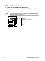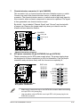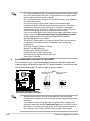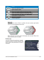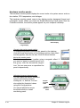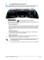
1
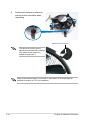
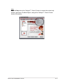
12. System panel connector (20-8 pin PANEL)
This connector supports several chassis-mounted functions.
PLED-
®
PLED+
PLED
SPEAKER
+5V
Ground
Ground
Speaker
P5E3 DELUXE
IDE_LED
Reset
Ground
PWR
Ground
IDE_LED+
IDE_LED-
PANEL
RESET
PWRSW
P5E3 DELUXE/WiFi-AP@n
System panel connector
2-34
* Requires an ATX power supply.
•
System power LED (2-pin PLED)
•
Hard disk drive activity LED (2-pin IDE_LED)
•
System warning speaker (4-pin SPEAKER)
•
ATX power button/soft-off button (2-pin PWRSW)
•
Reset button (2-pin RESET)
This 2-pin connector is for the system power LED. Connect the chassis
power LED cable to this connector. The system power LED lights up when
you turn on the system power, and blinks when the system is in sleep mode.
This 2-pin connector is for the HDD Activity LED. Connect the HDD Activity
LED cable to this connector. The IDE LED lights up or flashes when data is
read from or written to the HDD.
This 4-pin connector is for the chassis-mounted system warning speaker. The
speaker allows you to hear system beeps and warnings.
This connector is for the system power button. Pressing the power button
turns the system on or puts the system in sleep or soft-off mode depending
on the BIOS settings. Pressing the power switch for more than four seconds
while the system is ON turns the system OFF.
This 2-pin connector is for the chassis-mounted reset button for system
reboot without turning off the system power.
Chapter 2: Hardware information