1
A P P E N D I X
A
Regulatory Agency Statements
• • • • • • • • • • • • • • • • • • • • • • • • • • • • • • • • • • • • • • • • • • • • • • • •
UL Installation Requirements
The following requirements apply to both UL Residential and UL Commercial Burglary
installations:
• All partitions must be owned and managed by the same person(s).
• All partitions must be part of one building at one street address.
• The audible alarm device(s) must be placed where it/they can be heard by all partitions.
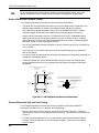
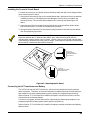
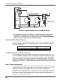
• The control cabinet must be protected from unauthorized access. This can be done by
installing a tamper switch on the cabinet door (supplied with the VISTA-100) or by
installing a UL Listed passive infrared detector positioned to detect cabinet access. Wire
the selected device to any EOLR supervised zone (zone 1-8). Program this zone for day
trouble/night alarm (type 05) or 24-hour audible alarm (type 07) response. You must use
the 24-hour alarm response for multi-partitioned systems.
• Remote downloading and auto-disarming are not UL Listed features.
UL864/NFPA Local Fire
Configure at least one bell output for supervision, and wire polarized fire alarm
indicators to the bell. Program this bell for temporal sounding.
UL864/NFPA Central Station and Remote Station Fire
• Size the backup battery for 24-hour standby (for central station) or 60-hour standby (for
remote station) time.
•
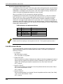
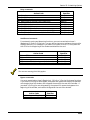
For central station service, you can use the 7720ULF or 7920SE LORRAs alone, the main dialer with a
LORRA, or the main dialer with the 5140DLM backup dialer module. For remote station service, you
must use the main dialer with the 5140DLM backup dialer module.
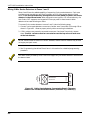
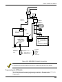
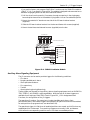
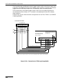
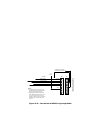
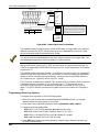
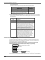
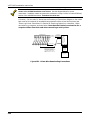
• When using the LORRA, connect its channel inputs to the VISTA-100's fire alarm, fire
supervisory (if one is used), and trouble triggers. Also connect its XMIT OKAY output
to Input 1 on the VISTA-100's J2 header. Program J2 Input 1 system zone 973 for 24hour trouble response (type 19) to send radio faults.
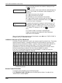
• When the main dialer is used, enable it (using field 3*30) and connect it to a telephone
line. Assign a 24-hour trouble response (type 19) to system zone 974 to enable main
dialer supervision. The VISTA-100 will activate the trouble trigger when it detects a
main dialer supervision fault.
•
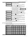
When the backup dialer is used, install it on the VISTA-100's PCB shield. Enable it (using field 3*30)
and connect it to a separate telephone line. Assign a 24-hour trouble response (type 19) to system zone
975 to enable backup dialer supervision.
• When the dialer is used, program it to send fire alarm, fire supervisory (if used), trouble,
AC loss, low battery, normal dialer test, and off-normal dialer test reports. Field *27
must be set to 024 maximum so that test reports are sent at least once every 24 hours.
Appendix A-1