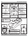
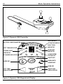
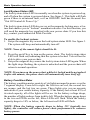
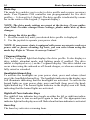
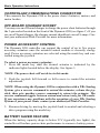
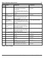
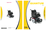
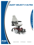
1
BASIC OPERATION INSTRUCTIONS Synergy TRU-Balance TM Dynamic G90 Controller ACN# 088 609 661 SAFETY GUIDELINES WARNING! An authorized Pride Provider or a qualified technician must perform the initial setup of this product and must perform all of the instructions in this manual. The symbols below are used throughout this owner's manual and on the controller to identify warnings and important information. It is very important for you to read them and understand them completely. WARNING! Indicates a potentially hazardous condition/ situation. Failure to follow designated procedures can cause either personal injury, component damage, or malfunction. On the product, this icon is represented as a black symbol on a yellow triangle with a black border. MANDATORY! These actions should be performed as specified. Failure to perform mandatory actions can cause personal injury and/or equipment damage. On the product, this icon is represented as a white symbol on a blue dot with a white border. PROHIBITED! These actions are prohibited. These actions should not be performed at any time or in any circumstances. Performing a prohibited action can cause personal injury and/or equipment damage. On the product, this icon is represented as a black symbol with a red circle and a red slash. NOTE: These instructions are compiled from the latest specifications and product information available at the time of publication. We reserve the right to make changes as they become necessary. Any changes to our products may cause slight variations between the illustrations and explanations in this manual and the product you have purchased. The latest/ current version of this manual is available on our website. Copyright © 2009 Pride Mobility Products Corporation INFMANU3721/Rev B/April 2009 Dynamic G90 Controller www.pridemobility.com TABLE OF CONTENTS LABEL INFORMATION ................................................................... 4 INTRODUCTION ................................................................................ 5 DYNAMIC G90 CONTROLLER .................................................... 7 PRECAUTIONARY GUIDELINES ............................................... 7 OPERATING THE DYNAMIC G90 CONTROLLER ............ 11 CONTROLLER COMMUNICATIONS CONNECTOR ......... 15 OFF-BOARD CHARGER SOCKET ............................................ 15 POWER ACCESSORY CONTROL ............................................. 15 BATTERY SAVER FEATURE ...................................................... 15 SLEEP MODE ..................................................................................... 16 OUT OF NEUTRAL AT POWER UP (OONAPU) .................. 16 ERROR CODES ................................................................................. 16 CARE AND MAINTENANCE ........................................................ 18 WARRANTY ....................................................................................... 18 www.pridemobility.com Dynamic G90 Controller LABEL INFORMATION PRODUCT SAFETY SYMBOLS The symbols below are used on the controller to identify warnings, mandatory actions, and prohibited actions. It is very important for you to read and understand them completely. Read and follow the information in the owner’s manual. Avoid exposure to rain, snow, ice, salt, or standing water whenever possible. Maintain and store in a clean and dry condition. Disposal and recycling - Contact your authorized Pride Provider for information on proper disposal and recycling of your Pride product and its packaging. This product has been tested and passed at an immunity level of 20 V/m. Dynamic G90 Controller www.pridemobility.com Basic Operation Instructions 5 INTRODUCTION WELCOME to Pride Mobility Products Corporation (Pride). The product you have purchased combines state-of-the-art components with safety, comfort, and styling in mind. We are confident that the design features will provide you with the conveniences you expect during your daily activities. Understanding how to safely operate and care for this product should bring you years of trouble free operations and service. Read and follow all instructions, warnings, and notes in this manual before attempting to operate your product for the first time. You must also read all instructions, warnings, and notes contained in any supplemental instructional booklets for the controller, front riggings, and/or seating system that accompanied your power chair before initial operation. Your safety depends upon you, as well as your provider, caretaker, or healthcare professional in using good judgement. This manual is to be used in addition to the power base owner’s manual that came with your power chair. If there is any information in this manual which you do not understand, or if you require additional assistance for setup or operation, please contact your authorized Pride Provider. Failure to follow the instructions, warnings, and notes in this manual and those located on your Pride product can result in personal injury and/or product damage and will void Pride’s product warranty. PURCHASER’S AGREEMENT By accepting delivery of this product, you promise that you will not change, alter, or modify this product or remove or render inoperable or unsafe any guards, shields, or other safety features of this product; fail, refuse, or neglect to install any retrofit kits from time to time provided by Pride to enhance or preserve the safe use of this product. INFORMATION EXCHANGE We want to hear your questions, comments, and suggestions about this manual. We would also like to hear about the safety and reliability of your new Pride product, and about the service you received from your authorized Pride Provider. Please notify us of any change of address, so we can keep you apprised of important information about safety, new products, and new options that can increase your ability to use and enjoy your Pride product. www.pridemobility.com Dynamic G90 Controller 6 Basic Operation Instructions NOTE: If you ever lose or misplace your product registration card or your copy of this manual, contact us and we will be glad to send you a new one immediately. My authorized Pride Provider Is: Name: Address: Phone Number: Purchase Date: Dynamic G90 Controller www.pridemobility.com Basic Operation Instructions 7 DYNAMIC G90 CONTROLLER The Dynamic G90 controller is a fully-programmable, modular electronic controller system that allows you to operate your power chair. It is designed to allow the user to have complete control over chair movement and speed. The controller has been pre-programmed to meet a typical user’s needs. The program is set using either a personal computer with software provided by the controller manufacturer or with a hand-held programmer, also provided by the controller manufacturer. WARNING! The controller program can affect speed, acceleration, deceleration, dynamic stability, and braking. If it is programmed incorrectly or outside of the safe limits as determined by your healthcare professional, it can create a dangerous situation. Only the power chair manufacturer, an authorized representative of the manufacturer, or a trained service technician should program the controller. PRECAUTIONARY GUIDELINES Before operating the Dynamic G90 Controller, please read the following. These guidelines are provided for your benefit and will aid you in the safe operation of the control system. Turn off the power to the controller when transferring to or from your power chair. Follow all of the procedures and heed the warnings as explained in your power chair owner’s manual. www.pridemobility.com Dynamic G90 Controller 8 Basic Operation Instructions Electromagnetic and Radio Frequency Interference (EMI/RFI) WARNING! Laboratory tests have shown that electromagnetic and radio frequency waves can have an adverse affect on the performance of electrically-powered mobility vehicles. Electromagnetic and Radio Frequency Interference can come from sources such as cellular phones, mobile two-way radios (such as walkie-talkies), radio stations, TV stations, amateur radio (HAM) transmitters, wireless computer links, microwave signals, paging transmitters, and medium-range mobile transceivers used by emergency vehicles. In some cases, these waves can cause unintended movement or damage to the control system. Every electrically-powered mobility vehicle has an immunity (or resistance) to EMI. The higher the immunity level, the greater the protection against EMI. This product has been tested and has passed at an immunity level of 20 V/m. WARNING! Be aware that cell phones, two-way radios, laptops, and other types of radio transmitters may cause unintended movement of your electrically-powered mobility vehicle due to EMI. Exercise caution when using any of these items while operating your mobility vehicle and avoid coming into close proximity of radio and TV stations. WARNING! The addition of accessories or components to the electrically-powered mobility vehicle can increase the susceptibility of the vehicle to EMI. Do not modify your power chair in any way not authorized by Pride. WARNING! The electrically-powered mobility vehicle itself can disturb the performance of other electrical devices located nearby, such as alarm systems. NOTE: For further information on EMI/RFI, go to the Resource Center on www.pridemobility.com. If unintended motion or brake release occurs, turn your controller off as soon as it is safe to do so. Contact Pride or your authorized Pride Provider to report the incident. Dynamic G90 Controller www.pridemobility.com Basic Operation Instructions 9 Dynamic G90 Controller Features Figure 1 provides information on the Dynamic G90 components and connections. Use this diagram to familiarize yourself with the function and location of each component before using the Dynamic G90 controller. The following functions are available with the Dynamic G90 controller: Joystick Control The joystick is used to control the direction and speed of the power chair. Actuator Adjustment The user can control positioning of the power actuators with the Dynamic G90 controller. Drive Profile Selection The user can select one of five available drive profiles. Sleep Mode This feature is designed to preserve battery charge and can be disabled through programming. Out of Neutral at Power Up (OONAPU) A safety feature designed to prevent the power chair from overheating and causing damage to the motors or controller. www.pridemobility.com Dynamic G90 Controller 10 Basic Operation Instructions 7 Segment Display Display for showing the selected drive profile. Also displays Drive Inhibit, Attendant Mode, & Lighting Mode when applicable. Actuator Indicator Lights Battery Condition Meter A series of six LEDs which indicates charge level. Left Leg Rest Hazard Right Turn ECU Icon Lock/System Status Headlight Elevate Right Leg Rest On/Off Key Toggles system power on and off. Headlights/ Hazard Key Toggles Headlights (short press) on and off. Toggles Hazard Lights (long press) on and off. When illuminated, these lights indicate the appropriate mode is activated. Mode Key Cycles through and selects one of the five drive profiles or the Actuator Mode. Back Recline When illuminated, these lights indicate the appropriate actuator is activated. Mode Indicator Lights Left Turn Seat Tilt Horn Key Activates the warning horn if pressed while system is powered on. Left/Right Indicator Keys Toggles Left or Right Indicator Lights on or off. Joystick Controls speed and direction. Can also be used for actuator control and selection. REARVIEW FRONTVIEW Off-board Charger Socket Connects to Battery Charger Plug. DXBUS Sockets Connects the DXBUS cable to the remainder of the DX system. Figure 1. Dynamic G90 Components and Connections Dynamic G90 Controller www.pridemobility.com Basic Operation Instructions 11 OPERATING THE DYNAMIC G90 CONTROLLER The Dynamic G90 controller is used to operate your power chair and all of its components. The Dynamic G90 controller consists of (See figure 2): 1. Joystick 2. Keypad & display 3. Controller communications connector 4. 3-pin off-board charger socket NOTE: This section describes standard Dynamic G90 control functions. If your controller is programmed with optional settings, consult your authorized Pride Provider for specific operational information. Joystick Control The joystick controls the direction and speed of your power chair. When you move the joystick from the neutral (center) position, the electromagnetic brakes release and allow your power chair to move. The farther you push the joystick from its neutral position, the faster your power chair moves. When you release the joystick and allow it to return to the neutral position, you engage the electromagnetic brakes. This causes your power chair to decelerate and come to a complete stop. Keypad and Display The keypad and display is located directly in front of the joystick. It contains keys and icons that you will use to control your power chair. See figure 3. On/Off Key The on/off key turns the system on and off. WARNING! Unless faced with an emergency situation, do not use the on/off key to stop the chair. This will cause the power chair to stop abruptly. WARNING! Always turn the power off when you are stationary to prevent unexpected movement. NOTE: If the joystick is not in the neutral (center) position when you turn on the power, you may cause a fault in the system. See “Out Of Neutral At Power Up.” www.pridemobility.com Dynamic G90 Controller 12 Basic Operation Instructions Figure 2. Dynamic G90 Controller DRIVE MODE & ACTUATOR DISPLAY BATTERY CONDITION METER RIGHT TURN INDICATOR LEFT TURN INDICATOR HEADLIGHT INDICATOR HAZARD LIGHT INDICATOR LOCK/SYSTEM STATUS LED ECU MODE INDICATOR ON/OFF KEY HEADLIGHTS/ HAZARD KEY MODE KEY HORN KEY RIGHT TURN INDICATOR KEY LEFT TURN INDICATOR KEY Figure 3. Dynamic G90 Keypad and Display Dynamic G90 Controller www.pridemobility.com Basic Operation Instructions 13 Lock/System Status LED The lock/system status LED is normally on when the system is powered up, and off when the system is powered down. See figure 3. This light will flash green if there is an internal fault, or if an OONAPU fault has occurred. See “Out Of Neutral At Power Up.” The lock/system status LED also serves as the magnetic locking area, a feature that enables you to “lockout” unauthorized users. For this function, you will need the magnetic key supplied with your power chair. If you lose this key, contact your authorized Pride Provider. To enable the lockout system: 1. Swipe the magnetic key across the lock/system status LED. See figure 3. The system will beep and automatically turn off. NOTE: None of the remote lights should be lit. 2. Press the on/off key to turn on the power chair. The lock/system status LED will flash red, indicating that the system is locked. You will not be able to drive your power chair. 3. Swipe the magnetic key across the lock/system status LED again. When the light stops flashing, the system is unlocked and the power chair will return to normal operation. NOTE: If you turn on the power chair while it is locked and do not unlock it after one minute, the power chair will automatically turn itself off. Battery Condition Meter The battery condition meter consists of six lights arranged in an arc over the 7 segment display. From left to right, the first two are red, the second two are orange, and the last two are green. These lights give you an accurate indication of your usable battery capacity. If the battery has at least 85% of its rated capacity, all of the lights will be on. As the battery voltage drops, the number of lights reduces from right to left. When the battery gauge drops to the two red LEDs on the left, these LEDs will flash. When the battery capacity drops to 10% or below, the left most red LED will flash. NOTE: When the battery capacity drops to below 21V (typically two lights), the controller will reduce power chair performance to conserve battery power. www.pridemobility.com Dynamic G90 Controller 14 Basic Operation Instructions Mode Key The mode key enables you to select a drive profile and a power accessory mode. Your Dynamic G90 controller was preprogrammed for five drive profiles— 1 (slowest) to 5 (fastest). The drive profile is indicated by a number in the center of the keypad (7 segment display). NOTE: The drive mode settings are preset at the factory. If your authorized Pride Provider changes these settings, please make note of these changes. To change the drive profile: 1. Press the mode key until your desired drive profile is displayed. 2. Use the joystick to operate your power chair. NOTE: If your power chair is equipped with power accessories such as a power seat or power elevating leg rests, you can select them using the mode key. Refer to “Power Accessory Control.” 7 Segment Display This is a 7-segment light that displays the drive profile. It also displays a drive inhibit, attendant mode, and lighting mode if enabled. The drive inhibit is displayed as a (-) on the 7-segment display. This drive inhibit can occur when using the onboard or off-board charger, or when an actuator is fully raised or extended. Headlights/Hazard Key To activate the headlights on your power chair, press and release (short press) the headlights/hazard key. The headlight indicator in the display area will illuminate indicating that the headlights are activated. To activate the hazard lights on your power chair, press and hold (long press) the headlights/hazard key. The hazard lights indicator in the display area will flash, indicating that the hazard lights are activated. Right/Left Turn Indicator Keys The right/left turn indicator keys toggle on either the left or right turn indicators. Press once to turn on and press again to turn off. The appropriate turn indicator light in the display area will flash when that turn indicator is activated. Horn Key The horn key activates a warning horn. Dynamic G90 Controller www.pridemobility.com Basic Operation Instructions 15 CONTROLLER COMMUNICATIONS CONNECTOR This connects the Dynamic G90 to the power chair’s batteries, motors, and motor brakes. OFF-BOARD CHARGER SOCKET You may use an off-board charger to charge the power chair batteries through the 3-pin socket located on the front of the Dynamic G90 (see figure 1). If you use an off-board charger, the charger current should not exceed 8 amps. Contact your authorized Pride Provider for more information. POWER ACCESSORY CONTROL The Dynamic G90 controller can support the control of up to five power accessory actuators once the actuator control module is correctly configured. Power accessory actuators are selected using the mode key and controlled using the joystick. To select a power accessory actuator: 1. Press the mode key until the desired actuator is indicated by the indicator lights located below the display. See figure 1. NOTE: The power chair will not drive in this mode. 2. Push the joystick full forward or full reverse to control the actuator adjustment. NOTE: When using the Dynamic G90 in conjunction with a TRx Seating System, give a reverse command to extend the actuator, release the joystick, then give another reverse command to retract the actuator. The reverse command toggles between extend and retract only for TRx units. If you experience any problems with the operation of your TRx Seating System or your power chair, contact your authorized Pride Provider. 3. Resume driving by moving the joystick back to neutral and selecting a drive program using the mode key. BATTERY SAVER FEATURE When the battery capacity drops to below 21V (typically two lights), the controller will reduce power chair performance to conserve battery power. www.pridemobility.com Dynamic G90 Controller 16 Basic Operation Instructions SLEEP MODE The power chair controller features a sleep mode that must be enabled through programming. Sleep mode is a built-in circuit that will automatically shut off the main power if the joystick is not moved in any direction for a period of time. This time factor is programmed into the controller. To restore power and continue, turn your power chair on. OUT OF NEUTRAL AT POWER UP (OONAPU) Your power chair joystick is equipped with Out Of Neutral At Power Up (OONAPU). If you power up the system and the joystick is not in the neutral position, the system status light flashes rapidly for either as long as the joystick is out of the neutral position or five seconds. After five seconds the system status LED will flash slowly. See “Error Codes.” ERROR CODES The system status light is displayed within the lock/system status LED represented by a key symbol located to the right of the drive mode display. This light is lit if the system is turned on. It also flashes in groups called error codes to indicate system faults. If your keypad displays one of these codes (see Table 1), contact your authorized Pride Provider. NOTE: You must turn the controller off and then on again to reset the controller, even if the source of the error is removed/corrected. In the event of an error, the system status light displays diagnostic indications. Errors are encoded as follows: one (DX Module fault) to twelve (module mismatch) and are displayed by the light flashing the number of times prescribed by the error code. The flash sequence (one to twelve) is followed by a long off period (2 seconds). If more than one error exists, then the error having the highest priority is indicated. The controller must be turned off and then on again even if the source of the error is removed. If you cannot resolve the problem, contact your authorized Pride Provider. Dynamic G90 Controller www.pridemobility.com Basic Operation Instructions Error Fault Code 1 2 3 4 5 6 7 8 9 10 11 12 Diagnosis DX Module Fault An auto download has occurred. The controller is not correctly programmed. The connection between the power module and the joystick module may be faulty. DX Accessory The accessory module (CLAM) has Fault a fault. Left Motor The connection between the power (or connection) module and the left motor is either Fault open or is shorted or the motor itself is shorted. Right Motor The connection between the power (or connection) module and the right motor is either Fault open or is shorted or the motor itself is shorted. Left Park Brake The connection between the power (or connection) module and the left park brake is Fault either open or shorted or the motor brake itself is shorted. Right Park Brake The connection between the power (or connection) module and the right motor brake is Fault either open or shorted or the motor brake itself is shorted. Low Battery Fault Battery voltage has fallen below 17 VDC. Over-voltage Fault The battery voltage has exceeded 32VDC. CANL Fault The DX Bus cable has a short or an open. CANH Fault The DX Bus cable has a short or an open. Stall Timeout The motor has been close to or at the programmed current limit. Module Mismatch There is an incompatibility between the DX modules in the system. 17 Solution See your authorized Pride Provider. See your authorized Pride Provider. Check left motor writing. Check right motor writing. Check motor/brake wiring. Check motor/brake wiring. Check that the battery wiring is secure. Check that the battery wiring is secure. See your authorized Pride Provider. See your authorized Pride Provider. Turn unit off, then on. See your authorized Pride Provider. Table 1. Error Codes www.pridemobility.com Dynamic G90 Controller 18 Basic Operation Instructions CARE AND MAINTENANCE Refer to your power chair owner’s manual for proper cleaning and disposal instructions. WARRANTY For two (2) years from the date of purchase, Pride will repair or replace at our option to the original purchaser, free of charge, the controller or any of its components found upon examination by an authorized representative of Pride to be defective in material and/or workmanship. Dynamic G90 Controller www.pridemobility.com NOTES www.pridemobility.com Dynamic G90 Controller Pride Mobility Products Corporation 182 Susquehanna Avenue Exeter, PA 18643-2694 USA Pride Mobility Products Company 380 Vansickle Road Unit 350 St. Catharines, Ontario L2R 6P7 Canada Pride Mobility Products Ltd. 32 Wedgwood Road Bicester, Oxon OX26 4UL UK Pride Mobility Products Australia Pty. Ltd. 21 Healey Road Dandenong, 3175 Victoria, Australia Pride Mobility Products Italia S.r.l. Via del Progresso - ang. Via del Lavoro Loc. Prato della Corte 00065-Fiano Romano (RM) Pride Mobility Products Europe B.V. Castricummer Werf 26 1901 RW Castricum The Netherlands *INFMANU3721*