1
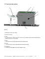
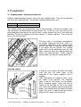
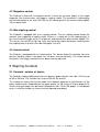
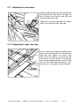
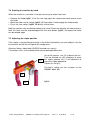
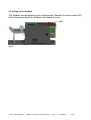
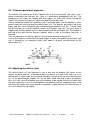
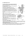
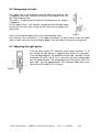
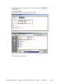
Foldnak Compact
User Manual
ENGLISH
Contents
Safety precautions .............................................................................................................. 4
1
Proper use .................................................................................................................. 5
1.1
Description and specifications ............................................................................ 5
1.2
Functional description......................................................................................... 6
2
Installation................................................................................................................... 7
2.1
Delivery conveyor ............................................................................................... 7
2.2
Dummy plug ....................................................................................................... 7
3
Preparation ................................................................................................................. 8
3.1
Stapling heads / Stapling head distance ............................................................ 8
Inserting staples.............................................................................................................. 8
3.2
Staples ............................................................................................................... 9
4
Operation .................................................................................................................. 10
4.1
Control Panel.................................................................................................... 10
4.2
Magazine control .............................................................................................. 12
4.3
Mis-stapling control........................................................................................... 12
4.4
Infeed control.................................................................................................... 12
5
Stapling booklets ...................................................................................................... 12
5.1
Formats / number of sheets ............................................................................. 12
5.1.1 Adjusting the side stops ............................................................................... 13
5.1.2 Adjusting the right side stop ......................................................................... 13
5.1.3 Adjusting the rear stop ................................................................................. 14
5.1.4 Adjusting the trigger mechanism .................................................................. 15
5.1.5 Adjusting the delivery conveyor.................................................................... 15
5.1.6 Stapling ........................................................................................................ 16
6
Accessories .............................................................................................................. 16
6.1
Stapling heads, staples .................................................................................... 16
6.2
Connection to collators ..................................................................................... 16
7
Service ...................................................................................................................... 17
7.1
Possible malfunctions....................................................................................... 17
Changing drivers ........................................................................................................... 17
7.2
Stapling head care and malfunctions ............................................................... 18
7.3
Cleaning rollers................................................................................................. 18
7.4
Rotating the machine by hand.......................................................................... 19
7.5
Adjusting the staple position............................................................................. 19
7.6
Pulling out the Foldnak ..................................................................................... 20
8
Trimmer .................................................................................................................... 21
8.1
Adjusting the back stop .................................................................................... 21
8.2
Trimmer operational sequence......................................................................... 22
8.3
Adjusting the delivery belt................................................................................. 22
8.4
Rotating the machine by hand.......................................................................... 23
8.5
Adjusting the knife ............................................................................................ 24
8.6
Sharpening the knife ........................................................................................ 25
8.7
Adjusting the light barrier.................................................................................. 25
9
Current overload protection switch ........................................................................... 26
10 Possible malfunctions, errors.................................................................................... 26
11 Softwareupdate via Laptop ....................................................................................... 28
Konformitätserklärung ....................................................................................................... 33
Änderungsindex ................................................................................................................ 34
© Ernst Nagel GmbH
9965201 User Manual Fk Compact
Rev 1.4
21.6.2010
S. 2
© Ernst Nagel GmbH
9965201 User Manual Fk Compact
Rev 1.4
21.6.2010
S. 3
Safety precautions
1. Please read this manual carefully and completely before operating the machine.
2. Please make sure the mains voltage is suitable and the outlet has a proper earth connection.
3. Repairs must be carried out by trained Nagel vendors and service technicians.
4. If the machine must be repaired, separate it from the mains by pulling the plug.
5. Caution! The Trimmer contains a very sharp knife. Be careful when removing paper jams!
6. Use original Nagel consumables and spare parts only.
7. Lay the cables in such a way that nobody can trip over them.
8. Install the machine in a dry room on level and solid ground, and make sure it is well accessible.
9. Block the breaks after putting the machine in place.
10. Safety devices must not be removed or bypassed.
11. Always replace fuses with new fuses of the same type and rating.
12. Users with long hair must keep a safe distance from rotating shafts and rollers.
13. When closing lids, take care that they do not fall down.
14. Do not open lids during operation - this could cause paper jams.
15. Connect the various devices with the screws provided so that they cannot be disconnected without tools.
16. Allow at least 20 seconds to pass between attempts to switch on the device; otherwise the software may
be damaged.
17. When changing plug connections, always switch off the machine!
18. Be careful with the leaf springs. They consist of thin sheet metal and may cause injury when handled
without proper caution.
© Ernst Nagel GmbH
9965201 User Manual Fk Compact
Rev 1.4
21.6.2010
S. 4
1 Proper use
Foldnak
Proper use of the Foldnak consists in the stapling and folding of paper within the limits
defined in the specifications.
Trimmer
Proper use of the Trimmer consists in the cutting of paper within the limits defined in the
specifications.
1.1 Description and specifications
Foldnak
The Foldnak is used to produce booklets. The paper to be processed is fed into the machine in sets, either manually or by a collator.
Please observe the physical limits when processing heavy paper. When paper of a higher
grammage is used, the maximum pile thickness (2.5 mm) of the booklets may have to be
reduced. A thickness of 2.5 mm corresponds to 25 sheets of 80 gsm paper.
Trimmer
The Trimmer is used to cut the faces of the booklets.
Power supply: see type plate on the machine
Serial number: see type plate on the machine
Year of construction: the first two digits of the serial number
Noise emission: < 70 dB(A)
© Ernst Nagel GmbH
9965201 User Manual Fk Compact
Rev 1.4
21.6.2010
S. 5
1.2 Functional description
4
2
1
6
3
5
fig 001
1. Switch panel with main switch
2. Delivery conveyor
3. Knob
• for adjusting the Foldnak and the Trimmer to the paper format and for operating the
motors by hand in service mode
4. Hood
• The machine can only be operated with the hood closed.
5. Drawer
• The machine can only be operated with the drawer closed.
6. Handwheel
• for adjusting and triggering the back jogging stroke
© Ernst Nagel GmbH
9965201 User Manual Fk Compact
Rev 1.4
21.6.2010
S. 6
2 Installation
• Remove the cardboard and packaging film
• Lift the machine from the pallet and set it down on a solid, level surface.
• Place the machine on adjusting feet, if necessary.
2.1 Delivery conveyor
See the enclosed installation instructions for information on how to mount the delivery
conveyor.
The shaft and the two wheels (10) are part of the accessories. They must be pre-mounted
with the enclosed set collars so that both wheels are positioned exactly above the green
transport belts when the shaft rests in the long vertical slots of the two shaft supports (11).
10
11
fig 002
Once the knurled screw has been loosened, the shaft supports on both sides of the delivery conveyor must be swung into a vertical position and secured.
2.2 Dummy plug
12
fig 002a
If no SP+ or Sp100 is connected, there must be 2710198 male dummy plug (12) inserted.
© Ernst Nagel GmbH
9965201 User Manual Fk Compact
Rev 1.4
21.6.2010
S. 7
3 Preparation
3.1 Stapling heads / Stapling head distance
Foldnak stapling-folding machines come with two stapling heads. They can be operated
with up to four stapling heads. The possible stapling head positions are:
Type
Foldnak C
Distances in mm
30 x 50 x 80 x 50 x 30
The stapling heads can be mounted in any of these positions. Pull back the feeder shoe
(26) and loosen the black plastic knurled screws (24). Lift off the staple saddle with the stapling head plate and loosen the two M4 Allen screws beneath with the 3 mm Allen key
provided. Pull off the stapling head and re-mount it in another position. Then install the
parts in the reverse order.
The driver (20) is re-mounted as described in
the chapter “Replacing the driver”. With a simultaneous adjustment of the stapling heads
and the side stops, the position of the staples
in the paper can be altered. The stapling
heads must not be positioned over the side
stops, especially when the stapling heads are
used in the outer positions. Finally, plug the
contact cable (19) onto the contact bank (18).
Inserting staples
In order to insert staples, pull back the feeder
shoe (26) with the index finger at the
underside of the staple magazine until it
engages.
Then swing back the magazine cover. Insert
the staples in this position. The magazine
holds a stick of 210 staples or ring staples.
When changing staples, make sure that no
staples of the old type are left in the magazine. Close the magazine cover and guide the
feeder shoe forward with the thumb and index
finger. Do not let it shoot forward too quickly,
otherwise the staple stick may break.
© Ernst Nagel GmbH
9965201 User Manual Fk Compact
Rev 1.4
21.6.2010
S. 8
3.2 Staples
Foldnak stapling-folding machines use the following Nagel staples:
• 26/6
26 = Wire gauge
6 = Shank length in mm
for 2 up to ca. 20 sheets
• 26/8 S
26 = Wire gauge
8 = Shank length in mm
S = Steel wire
for 15 up to ca. 40 sheets
• Ri 26/6
Ri = Ring staples
26 = Wire gauge
6 = Shank length in mm
for 2 up to ca. 20 sheets
Use only original Nagel staples. They are precision-made and therefore guarantee troublefree and accurate functioning.
We can only honour the stapling head guarantee if Nagel staples are used.
© Ernst Nagel GmbH
9965201 User Manual Fk Compact
Rev 1.4
21.6.2010
S. 9
4 Operation
4.1 Control Panel
38
37
36
35
34
33
32
31
30
1234
fig005
30. Start
• Press once to start the infeed belt.
• Press while the infeed belt is running to trigger a stapling stroke.
31. Counter
• Reset counter
• Displays error code in case of an error:
Paper jam in Online box
Paper jam in front of light barrier, infeed belt, Trimmer
Paper jam in front of light barrier, delivery belt, Trimmer
Paper jam at booklet stop, Trimmer
Staples empty
Error home position
Error under light barrier, infeed belt, Trimmer
Error under light barrier, delivery belt, Trimmer
Timeout knife stroke
Timeout stapling stroke
Door open
Error S8
Error SP +
2
3
4
5
6
7
8
9
10
11
12
13
14
32. Main switch
• An additional main switch is located above the mains plug. If the machine is not used
for a prolonged period, it should be switched off at this switch.
© Ernst Nagel GmbH
9965201 User Manual Fk Compact
Rev 1.4
21.6.2010
S. 10
33 Error LED
• Green if everything is OK.
• Red in case of error.
34 Reset button
• Acknowledgement of errors.
• Keep pressed for a few seconds to reset the reset counter to zero.
35 Service switch
• Position I is normal mode.
• Position II allows motors to be turned manually.
36 Bypass switch
• Switches off the trim function. The booklets run through the trimmer without being
trimmed.
37 Potentiometer for the trimmer delivery belt
• Adjustment see below.
38 Potentiometer for the conveyor
• Adjusts the shingles.
© Ernst Nagel GmbH
9965201 User Manual Fk Compact
Rev 1.4
21.6.2010
S. 11
4.2 Magazine control
The Foldnak is fitted with a magazine control. If there are no more staples in the staple
magazine, the machine does not trigger a stapling stroke. This condition is indicated by
the red illumination of the error LED (33) on the control panel if the contact cable (fig003,
19) has been fitted.
4.3 Mis-stapling control
The Foldnak is equipped with a mis-stapling control. The mis-stapling control keeps the
machine from triggering a stapling stroke if there is a staple jam in the stapling head. In
this case the driver jumps out of its suspension and touches the spiral contact (fig003, 15).
This causes the red LED to light up. Once any remaining staples have been removed from
the stapling head, the driver must be fitted again (see 8.3).
4.4 Infeed control
The Foldnak is equipped with an infeed control. This device keeps the machine from triggering a working stroke if the paper has not been inserted correctly. The infeed control
only works if the trigger mechanism has been correctly adjusted.
5 Stapling booklets
5.1 Formats / number of sheets
The Foldnak stapling-folding machines can process paper formats from 105 x 210 mm up
to 320 x 450 mm. This includes for instance DIN A3, A4 and A5.
The number of sheets that can be made into a booklet depends on the thickness of the
paper and the cover. Depending on the paper quality, ca. 30 sheets of 70 gsm paper or 25
sheets of 80 gsm paper can be made into booklets with 120 or 100 pages. If a cardboard
cover is used the number of sheets must be reduced accordingly.
© Ernst Nagel GmbH
9965201 User Manual Fk Compact
Rev 1.4
21.6.2010
S. 12
5.1.1 Adjusting the side stops
Begin by adjusting the left side stop with the
assistance of the scale (38) on the table. To
do so, loosen the knurled screw (39) and
move the stop to the side.
Tighten the knurled screw after the adjustment. Then adjust the right side stop.
5.1.2 Adjusting the right side stop
Insert a sheet of the paper to be processed,
loosen the knurled screw (41) and move the
right stop flush against the sheet. From
there, move the stop ca. 4 mm to the right
and secure it in this position. This guarantees that the jogging mechanism that is built
into the right side stop and covers a distance of ca. 4 mm adjusts the pile correctly.
© Ernst Nagel GmbH
9965201 User Manual Fk Compact
Rev 1.4
21.6.2010
S. 13
5.1.3 Adjusting the rear stop
The rear stop (fig008, 44) is adjusted using
the knob (fig001, 3) on the left side of the
machine. Insert a sheet of the paper to be
processed. Turn the knob until the upper
edge of the paper aligns with the format mark
(for DIN formats), which corresponds to the
paper format on the scale of the feed table.
The adjustment of the rear stop must be
checked in a stapling test.
© Ernst Nagel GmbH
9965201 User Manual Fk Compact
Rev 1.4
21.6.2010
S. 14
5.1.4 Adjusting the trigger mechanism
The adjustment is made while the machine is switched off. The Foldnak has an adjustable
photo cell with a connected baffle plate (48) below the feed table.
47
48
fig009
Adjustment:
Switch off the Foldnak.
Insert a sheet of the format to be used.
Switch on the Foldnak and press Start.
Turn the handwheel (fig001, 6) until the jogging plate (48) touches the upper edge of
the sheet.
• Position the pinch roll (47) slightly above the sheet edge.
• The stapling stroke of the Foldnak is triggered automatically as soon as the stack of
sheets is jogged.
•
•
•
•
5.1.5 Adjusting the delivery conveyor
In order to be able to optimally utilise the capacity of the delivery conveyor (fig001, 2), the
feed rate of the booklets onto the delivery conveyor can be adjusted. The feed rate, i.e.
overlapping of individual booklets on the delivery conveyor, is adjusted at the rotary switch
(fig005, 38).
The distance of the Foldnak retaining wheels must also be adjusted. To do this, you must
adjust the shaft supports (fig002, 11). A rule of thumb is that for small formats, the wheels
must be closer to the Foldnak, and further away for larger formats. The user must find the
best adjustment for a given booklet.
© Ernst Nagel GmbH
9965201 User Manual Fk Compact
Rev 1.4
21.6.2010
S. 15
5.1.6 Stapling
After the machine is switched on, the paper is laid onto the feed table. If it is inserted correctly, the machine is triggered automatically. The first stapling should be a test to check
the adjustments. The staples should be the same distance from the upper and the lower
edge of the booklet, they should be exactly in the fold, and the fold should be in the middle
of the format. Adjust the stops if necessary.
6 Accessories
6.1 Stapling heads, staples
•
•
•
•
No. 2932600: Additional stapling heads
No. 6272060: 5,000 staples 26/6
No. 6272081: 5,000 staples 26/8S
No. 6274062: 5,000 ring staples Ri 26/6
6.2 Connection to collators
Booklets can be produced more cost-effectively with an automatic paper feed. This is
possible if the Foldnak is connected to a collator.
© Ernst Nagel GmbH
9965201 User Manual Fk Compact
Rev 1.4
21.6.2010
S. 16
7 Service
7.1 Possible malfunctions
• Machine does not function: Mains plug connected? Main switch switched on? Safety
covers open?
• Power fails: Reset the circuit breaker (50) after a short time.
50
Changing drivers
Drivers are wear parts and must be replaced occasionally. The driver (fig003, 20) is
suspended from a spigot (fig003, 16) and secured with a knurled screw (fig003, 17).
In case of an overload, it jumps off the spigot and is pushed up until it touches the spiral
contact (fig003, 15) and thereby activates the mis-stapling control. A precondition for this
is that the contact cable (fig003, 19) is mounted, which connects the stapling head with
the contact bank. When the knurled screw (fig003, 17) is loosened the driver can be reconnected to the spigot.
Then the knurled screw must be tightened again.
To replace the driver, loosen the knurled screw, pull the driver off the spring-mounted
spigot, and pull it upwards out of the stapling head guide. To install the new driver, guide
the driver in from above and connect it to the spigot.
Tighten the knurled screw. When changing the driver, be sure that the engraving “26” at
the upper end of the driver points towards the operator. Foldnak stapling-folding machines
are delivered with ring drivers (item no. 2932619) that permit stapling with ring staples or
standard staples. Instead of the ring driver, a flat driver (item no. 2932616) can be used
for thick paper stacks.
© Ernst Nagel GmbH
9965201 User Manual Fk Compact
Rev 1.4
21.6.2010
S. 17
7.2 Stapling head care and malfunctions
Damaged staples must be removed from the staple channel of the stapling head. Pull
back the feeder shoe (fig004, 26) until it engages, then loosen both knurled screws
(fig004, 24) and swing the straps (fig004, 27) towards the bottom.
The stapling head can be pulled off after the contact wire has been removed. Clear the
remaining staples from the front plate of the stapling head with the magazine and from the
front plate still in the machine.
Then replace the stapling head and tighten the knurled screws (24). Staple remnants in
the guide channel can lead cause the driver to break. Therefore be sure to thoroughly
clean the guide channel after every time mis-stapling. Apply a very thin layer of grease to
the driver above the stapling head after every 5,000 staplings.
Clean the stapling head regularly, otherwise the accumulated dirt may cause malfunctions.
Should there not be any staples in the paper although the magazine is full: Check whether
the feeder shoe is bent open at the front due to accidentally being allowed to spring forward. If this is the case then carefully file off these burrs so that the feeder shoe can again
move all the way into the stapling head.
7.3 Cleaning rollers
With time, printing ink can collect on the rollers. This can reduce the rollers’ grip. For this
reason the rollers must be cleaned as needed using a cleaning agent suitable for folding
machines or printing rollers.
© Ernst Nagel GmbH
9965201 User Manual Fk Compact
Rev 1.4
21.6.2010
S. 18
7.4 Rotating the machine by hand
When the machine is serviced, it may be necessary to rotate it by hand.
• Remove the knob (fig001, 3) for the rear stop, open the sheet-metal cover and re-insert
the knob.
• Move the wide service switch (fig005, 35) to position I to disengage the motor brake.
• Press the start switch (fig005, 30) briefly several times.
Now the machine can be rotated clockwise by hand. Since the machine will now register a
fault, this fault must be acknowledged with the reset button (fig005, 34) before the motor
can be rotated again.
7.5 Adjusting the staple position
If the staple is not positioned centrally in the fold of the booklet, you can readjust it via the
knurled nuts on the left and right of the wedge arms.
Attention! Always adjust both 2955232 knurled nuts evenly!
2 revolutions max. as the folding knife may be damaged otherwise.
63
Use a flat spanner, size 13, to loosen the nut.
Turn the knurled nut (62) clockwise to move
the staple upward, turn it anti-clockwise to
move the staple downward.
Tighten the nut (61).
The basic setting can be restored via the
2955007 block (63).
61
62
© Ernst Nagel GmbH
fig010
9965201 User Manual Fk Compact
Rev 1.4
21.6.2010
S. 19
7.6 Pulling out the Foldnak
The Foldnak can be pulled out for maintenance. Remove the two screws (65)
of the housing and pull the Foldnak out toward the rear.
65
fig011
© Ernst Nagel GmbH
9965201 User Manual Fk Compact
Rev 1.4
21.6.2010
S. 20
8 Trimmer
8.1 Adjusting the back stop
The back stop is used to adjust the dimension T. The paper face to be trimmed must be
wider the thicker the booklet is. The dimension T is anywhere between 225 mm max. and
100 mm min.
fig012
Fold up the cover.
Loosen the locking screw (28).
Fit the handwheel (29).
Adjust the back stop with the handwheel (29).
Tighten the locking screw (28).
fig013
28
29
fig014
© Ernst Nagel GmbH
9965201 User Manual Fk Compact
Rev 1.4
21.6.2010
S. 21
8.2 Trimmer operational sequence
The booklet (46) coming out of the Foldnak falls onto the infeed belt (40) and is transported underneath the knife bar (44). Here it is detected by photoelectric cell (43). The
photoelectric cell stops the feeding belt and triggers the knife (45) stroke. During the
stroke, the knife bar (44) presses against the fold of the booklet (46).
After a completed stroke the infeed belt (40) is activated again and the booklet is transported under the knife and onto the delivery belt (41). The delivery belt takes it up to the
paper stop (48). Here the booklet (46) is detected by photoelectric cell (47). The cell stops
the delivery belt (41) and the booklet remains at the paper stop (48). The next stroke is
triggered by another booklet that has been placed onto the infeed belt (40). The booklet is
pressed at the fold and the previous booklet, which is now at the paper stop (48), is
trimmed.
Then the booklet on the delivery belt (41) falls onto the delivery conveyor (42).
If no further booklet is delivered that could trigger a stroke, the booklet at the paper stop
(48) is trimmed by an automatic stroke after about 5 seconds and delivered via the
delivery belt (41).
fig015
8.3 Adjusting the delivery belt
The delivery belts (41) are adjusted in such a way that the booklet (46) comes to rest
against the back stop (48). If the booklet does not always rest against the stop, e.g. if it is
positioned at a slight angle, this can be corrected by increasing the lag of the delivery belts
(41) at the potentiometer (fig005, 37). On the other hand, too long a lag of the delivery
belts (41) may cause the bottom layer of the booklet to be moved further by the belt than
the fold, especially in case of thick booklets and booklets without cardboard cover. After
trimming, the bottom layer then extends and projects slightly beyond the trimmed face. In
this case, reduce the lag slightly.
© Ernst Nagel GmbH
9965201 User Manual Fk Compact
Rev 1.4
21.6.2010
S. 22
8.4 Rotating the machine by hand
For service tasks or in the case of a malfunction it may be necessary to rotate the machine manually.
• Remove the knob (fig001, 3) from the back stop, open the sheet-metal cover and reinsert the knob.
• Move the service switch (fig005, 35) to position II to release the motor brake.
The machine can now be rotated manually.
After completing service tasks:
Turn the machine to the upper dead centre (the knife bar is right at the top).
Move the service switch to position I to apply the motor brake.
Remove the knob.
© Ernst Nagel GmbH
9965201 User Manual Fk Compact
Rev 1.4
21.6.2010
S. 23
8.5 Adjusting the knife
The pressing mechanism (61) must be removed for all
assembly or adjustment work carried out on the knife. To
do so, undo the screws (60) and remove the pressing
mechanism toward the side.
The upper knife (45) is screwed to the knife bar by 5
M6x16 DIN 933 hexagon screws.
The lower knife is adjusted to the upper knife.
The lower knife (63) is secured by five cylinder screws
(62) and supported by four clamping screws (65).
At the beginning the clamping screws (65) must be undone far enough so that the lower knife can be moved
away slightly from the upper knife when the screws (62)
are loosened. Now the upper knife is turned downwards
by hand.
To do so, place the handwheel (fig001, 3) on the gear
fig016
shaft.
Open the protective cover (fig001, 4).
Release the motor brake with switch (fig005, 35).
Carefully turn the handwheel anti-clockwise in the
direction of the arrow. The upper knife moves downwards and must not touch the lower knife (63).
Rather, there must be a small clearance between the
upper and lower knives.
Insert a 60 gsm sheet of paper into the gap between
the upper and lower knives; this sheet represents the
distance to be set.
Push the lower knife (63) against the upper knife (45)
fig017
until the paper is tightly clamped.
Tighten the screws (62) lightly with the box spanner – not too tightly; the lower knife must
still be able to move when the clamping screws (65) are shifted. The clamping screws (65)
are now brought into contact with the lower knife by hand.
Tighten the screws (62) firmly.
Turn the upper knife up and down again with the handwheel. This is done to ensure that
the adjustment is not too tight and that the paper used for adjustment can be removed.
Move switch (fig005, 35) to apply the brake, remove the handwheel (fig001, 3).
© Ernst Nagel GmbH
9965201 User Manual Fk Compact
Rev 1.4
21.6.2010
S. 24
8.6 Sharpening the knife
The upper knife is more delicate than the lower knife and must be
sharpened more often. Remove the knife as described in the section “Adjusting the knife”.
The knife is sharpened at the bevel of the blade with an angle of
24 degrees.
As the upper knife is not normally sharpened (and thereby made
thinner) on the front side, it may not be necessary to readjust the
lower knife.
fig018
After re-inserting the upper knife, turn it downward by hand
very carefully (see instructions). If the upper knife does not easily move under the lower
knife, or does not cut a sheet of 80 gsm paper, then the lower knife must be readjusted.
8.7 Adjusting the light barrier
Turn the rotary switch (71) clockwise to the stop in position “L“. At
this setting the light barrier is triggered only when it is free again.
Turn the potentiometer (70) clockwise to the stop. The red (72) and
the green (73) LEDs are lit. This is the most sensitive setting. Now
turn the potentiometer (70) anticlockwise until the green LED (73)
goes dark. Turn the potentiometer (70) clockwise about half a turn
so that the LED diode (73) is lit again.
fig019
© Ernst Nagel GmbH
9965201 User Manual Fk Compact
Rev 1.4
21.6.2010
S. 25
9 Current overload protection switch
50
The current overload protection switch prevents overloading of the
motor by switching it off.
When this happens, eliminate the cause of the malfunction and then
reset the current overload protection switch (50).
fig020
10 Possible malfunctions, errors
Error:
The booklet rests against the stop and does not move easily away from the stop.
The knife does not cut cleanly and produces a fibre ridge that hooks behind the knife and
stops the booklet.
Remedy:
Narrow the adjustment of the lower knife.
Make sure the strip of trimmed paper is not too narrow, so that the lower knife is behind
the lowest paper layer.
Error:
A stroke is triggered, knife remains down.
Brake release switch open.
Remedy:
Close the brake release switch (Fig005, 35), press the reset button (Fig005, 34).
Error:
The machine is switched on, the booklet runs through from rear to front without a stroke
being triggered.
Bypass run is activated at switch (Fig005, 36).
Toggle the switch (Fig005, 36), press the reset button (Fig005, 34).
Error:
If the path between the light barriers (43) and (47) is not cleared after a certain time in
normal operation, the machine assumes that there is a paper jam and switches off.
Remedy:
After the paper jam has been removed, the machine must be made ready again for operation with a reset stroke. To do this, press the reset button (Fig005, 34).
© Ernst Nagel GmbH
9965201 User Manual Fk Compact
Rev 1.4
21.6.2010
S. 26
Error:
In connection with a SP+ a paper jam occurs again and again.
Remedy:
Boost the delay time of the infeed belt a bit, so that the brochure has more time to get into
the SP+.
Error codes displayed in case of a fault:
Paper jam in Online box
Paper jam in front of the light barrier, infeed belt, Trimmer
Paper jam in front of the light barrier, delivery belt, Trimmer
Paper jam at booklet stop, Trimmer
Staples empty
Error home position
Error under the light barrier, infeed belt, Trimmer
Error under the light barrier, delivery belt, Trimmer
Timeout knife stroke
Timeout stapling stroke
Door open
Error S8
Error SP +
2
3
4
5
6
7
8
9
10
11
12
13
14
How to test sensors and actuators:
Sensor test:
Enter ”sen 1“ in the terminal programme or switch on DIP 8 and turn machine off/on
Output of the changes via error LED or in the terminal programme
Enter “sen 0” in the terminal programme or switch off DIP 8 and turn machine off/on
to deactivate the sensor test
Actuator test:
Enter ”akt 1“ in the terminal programme or switch on DIP 7 and turn machine off/on:
Bypass switch for all belts + conveyor, reset button for trim stroke; release button for stapling stroke
Enter “akt 0” in the terminal programme or switch off DIP 7 and turn machine off/on
to deactivate the actuator test
© Ernst Nagel GmbH
9965201 User Manual Fk Compact
Rev 1.4
21.6.2010
S. 27
11 Softwareupdate via Laptop
© Ernst Nagel GmbH
9965201 User Manual Fk Compact
Rev 1.4
21.6.2010
S. 28
© Ernst Nagel GmbH
9965201 User Manual Fk Compact
Rev 1.4
21.6.2010
S. 29
© Ernst Nagel GmbH
9965201 User Manual Fk Compact
Rev 1.4
21.6.2010
S. 30
© Ernst Nagel GmbH
9965201 User Manual Fk Compact
Rev 1.4
21.6.2010
S. 31
© Ernst Nagel GmbH
9965201 User Manual Fk Compact
Rev 1.4
21.6.2010
S. 32
Konformitätserklärung
DECLARATION OF CONFORMITY
DÉCLARATION DE CONFORMITÉ
Wir/ We/ Nous:
Breitwiesenstr. 21
70565 Stuttgart
Germany
Ernst Nagel GmbH
erklären in alleiniger Verantwortung, dass das Produkt/
declare under our sole responsibility that the product/
déclarons sous notre seule responsabilité que le produit
Foldnak Compact
auf das sich diese Erklärung bezieht, in Übereinstimmung ist mit den Bestimmungen
der EU Richtlinien/
to which this declaration relates is in conformity with the essential requirements of
EEC directives/
auquel se réfère cette déclaration est en conformité avec les exigences essentielles
des directives de la communauté européenne
89/336/EEC
89/392/EEC
73/23/EEC
und Änderungen/ and amendments/ et amendements
und Änderungen/ and amendments/ et amendements
und Änderungen/ and amendments/ et amendements
unter Anwendung der folgenden harmonisierten Normen/
by applying the following harmonized standards/
en appliquant les normes harmonisées suivantes
EN 60204-1
prEN 1010
EN 60950
EN 55022
EN 55024
EN 61000-3-2
EN 61000-3-3
06.93
10.99
08.92, + A1 + A2 + A3 + A4 + A11
09.98 Klasse B/ class B/ classe B
09.98
04.95 + A1 + A2 + A14
01.95
Jahr der Anbringung der CE-Kennzeichnung/
Year of affixing the CE marking/
L' an de l' application de la marque CE:
2009
Stuttgart, 16.2.2009
Ort und Datum/
Place and date/
Lieu et date
© Ernst Nagel GmbH
Geschäftsführer/
Managing Director/
Gérant
9965201 User Manual Fk Compact
Rev 1.4
21.6.2010
S. 33
Änderungsindex
Rev. 1.0
12.2.09
Rev. 1.2
30.09.09:
Softwareupdate via Laptop hinzu
Rev. 1.3
4.12.09:
Error in connection with SP+
Rev. 1.4
21.6.10
2.2 Dummy plug hinzu
© Ernst Nagel GmbH
9965201 User Manual Fk Compact
Rev 1.4
21.6.2010
S. 34
© Ernst Nagel GmbH
9965201 User Manual Fk Compact
Rev 1.4
21.6.2010
S. 35
Ernst Nagel GmbH
D – 70565 Stuttgart, Germany
Inland
0711 78078 11
Export +49711 78078 21
Telefax +49711 78078 10
www.ernstnagel.com