1
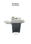
TRIMMER
User manual
English
Contents
Contents .........................................................................................................................2
Description of function..................................................................................................3
Safety rules ....................................................................................................................4
Installation .....................................................................................................................4
Coupling with Foldnak ..................................................................................................5
Mounting the fan-form transport device .......................................................................6
Adjustment of the depth stop.........................................................................................6
Switch-on .......................................................................................................................7
Trimmer function sequence ...........................................................................................7
Operator control panel ...................................................................................................8
Adjusting the run-in conveyor.......................................................................................8
Adjusting the run-out conveyor.....................................................................................8
Service switches.............................................................................................................9
Run-through program at the trimmer ............................................................................9
Turing the machine manually ......................................................................................10
Adjusting the knife ......................................................................................................11
Sharpening the knife....................................................................................................12
Adjusting the light barrier ...........................................................................................12
Current overload protection switch .............................................................................12
Possible malfunctions ..................................................................................................13
Technical data ..............................................................................................................14
Conformity statement ..................................................................................................14
2
Description of function
4
5
6
3
7
2
1
9
8
1 Master switch
• Emergency shut-off switch
2 Service switches
3 Operator control panel
4 Handwheel
5 Opening for mounting the handwheel on the gear shaft
6 Protecting lid
• The machine can be operated only when the protecting lid is closed.
7 Coupling strip
8 Drawer box
• The machine can be operated only when the drawer box is closed.
9 On button
Warning: Trimmer is only allowed to be operated
when connected to a Foldnak.
3
Safety rules
The machine may be operated only in the coupled state with Foldnak.
Only carry out repairs with original NAGEL spare parts.
Only carry out repairs after disconnecting from the mains electricity supply.
Repairs and work upon electric appliances may only be carried out by trained tradesmen.
Removal of safety equipment and casing and operation with damage that affects
safety is forbidden (e.g. damaged electricity cables, covering).
Use the machine exclusively to cut paper and cardboard.
Lay out the electricity cable in such a way that it does not form any kinks.
Work place of the operator: in front of the machine.
Only erect the machine in a dry room.
Installation
In order that the machine can be rolled off the palette, remove all retaining screws
which secure the lugs to the palette.
Pull out both girders (12) from under the
machine and use them as supports under
the ramp (11).
Screw out the transport securing screws
(10).
Set up the machine on a solid and level
surface.
4
Coupling with Foldnak
Unhook the fan-form transport device on the rear
panel of the Foldnak. Unscrew the rear protecting
plate (14) of the Foldnak. Thereby make sure that the
shaft (13) of the protecting plate is in the operating
setting, i.e. the Foldnak must be ready for operation
at switch-on time. If necessary, turn the shaft (13) by
the required amount to fulfil this condition.
Attach the guide bracket (15) on the coverplate of the
Foldnak with two FG screws (16).
Unscrew the two screws (20) on the left and right so
that the coupling strip (7) can be mounted.
Screw down the coupling strip (7) and the spacer
tube (19) with the cylinderhead screw (18) (from the
bag of accessories) on the Foldnak.
Push the Foldnak against the trimmer such that the
protruding table of the trimmer extends into the
Foldnak. Push the coupling strip (7) over the perforated plate (22) of the trimmer. Pin the screws left
and right (21) and fix them with self-locking nut
(bypack accessories).
5
Mounting the fan-form transport device
Hook the fan-form transport device (24) on the trimmer into the cylinderhead screws (27).
Slightly raise the fan-form transport device and introduce the rod (25) as support into the breakout on
the trimmer
Insert the plug (26) into the socket on the trimmer.
The fan-out size is set with the potentiometer (35).
Adjustment of the depth stop
The depth stop serves to adjust the T measurement. The brochure has to be thicker as
the end of paper to be cut of is wider. The
T measurement can be max. 225 mm and
min. 100 mm.
Open the protective cover (6).
Release the clamp screws (28) on the left
and right.
Adjust the depth stop on the handwheel
(29).
Tighten the clamp screws (28) again.
6
Switch-on
Switch-on the trimmer at the master switch.
Press the on button
The machine executes a reset stroke.
The machine is therewith ready for operation.
The green diode (30) on the operator control panel is lit and the run-in conveyor (40)
is running.
Trimmer function sequence
The brochure (46) coming out of the Foldnak falls onto the feeding belts (40) and is
transported up to underneath the cutter bar
(44). Here it is recognised by photoelectric
cell (43). The photoelectric cell stops the
feeding belts and triggers the knife (45)
stroke. The cutting bar (44) presses the
brochure in the fold during this.
After a completed stroke the feeding belts (40) again switches on and the brochure
runs through, under the knife onto the delivery belts (41). It is transported by the delivery belts up to the paper stop (48). Here the brochure (46) is recognised by photoelectric (47). This stops the delivery belts (41) and the brochure remains laying
against the paper stop (48). A next stroke is triggered by a further brochure, which
has been delivered onto the feeding belts (40). This presses the brochure in the fold
and the previous brochure, which is against the paper stop (48), is cut. Subsequently
the brochure delivered onto the delivery belts (41) falls onto the slat conveyor (42).
In the event of no further brochure being delivered and triggering a stroke, a brochure leaning against the paper stop (48) is trimmed by an automatic stroke trigger
after about 5 seconds and delivered via the delivery belts (41).
7
Operator control panel
(30) Green Diode
Trimmer ready for operation
(31) Red Diode
Reset stroke is executed
(32) Yellow Diode
Paper jam at run-out conveyor
(33) Yellow Diode
Paper jam at run-in conveyor
(34) Reset Button
To start a reset stroke
(35) Potentiometer
To set the fan-out size
(36) Potentiometer
For adjusting the run-out conveyor
(37) Potentiometer
For adjusting the run-in conveyor
Adjusting the run-in conveyor
The run-in conveyors (40) are adjusted such that the brochure (46) will come to lie
approximately in the centre of the press beam (44).
If the brochure comes to rest ahead of or beyond this position, the after-run of the
run-in conveyors (40) must be adjusted by changing the setting of the potentiometer
(37) accordingly.
Adjusting the run-out conveyor
The run-out conveyors (41) are adjusted such that the brochure (46) comes to lie
against the depth stop (48). If the brochure does not always lie against the stop, e.g.
if it rests slightly oblique, this can be corrected by setting longer after-run of the runout conveyors (41) by turning the potentiometer (36) correspondingly. On the other
hand, too long after-run of the run-out conveyors (41) can, especially for thick layers
and ones without cardboard cover, cause the bottom layer of the brochure to be
moved further by the conveyor run than the fold. After cutting, the bottom layer then
extends and projects slightly beyond the cut.
8
Service switches
(50) Current overload protection switch
The stroke motor switches off when overloaded see also the chapter headed „Current overload protection switch“
(51) Brake release switch
Switch pressed on the left Brake released
Switch pressed on the right Brake engaged see also chapter headed „Turning
the machine manually“
(52) Bypass mode switch
Switch pressed on the left Bypass mode
active Switch pressed on the right Bypass mode not active see also chapter headed
„Run-through program at the trimmer“
Run-through program at the trimmer
When the run-through program is activated, the brochures run through the machine
without being cut.
Switch-on the machine at the master switch.
Press the bypass mode switch (52) on the left to activate the bypass mode.
Press the reset button.
Both transport conveyors run.
Deselect the run-through program.
Press the bypass mode switch (52) on the right to deselect the bypass mode.
Press the reset button.
Only the run-in conveyor is running.
9
Turing the machine manually
For service tasks or in the case of disturbances it may be necessary to turn the machine manually.
Open the protecting lid.
For this purpose switch-on the machine at
the master switch.
Screw-off the cover of the switches.
Press the brake release switch (51) on the
left to release the stroke motor brake.
Mount the handwheel (4) on the gear
shaft (5).
The machine can now be turned in the
direction of the arrow (arrow on the handwheel).
After completing service tasks:
Turn the machine to the upper dead point (the knife beam is right at the top).
Take off the handwheel again.
Press the brake release switch on the right to engage the stroke motor brake.
Screw-down the cover of the switches.
Press the on button.
Close the protecting lid.
10
Adjusting the knife
The press (61) is to be unscrewed for all assembly or
adjustment work carried out on the knife. For this,
unscrew screws (60) and remove the press to the
side.
The upper knife (45) is screwed tightly to the cutter
bar by 5 M6x16 DIN 933 hexagonal screws.
The lower knife is adjusted to the upper knife.
The lower knife (63) is secured by five cylinder
screws (62) and supported by four pressure screws
(65).
At the beginning the pressure screws (65) are to be
screwed back far enough so that the lower knife can
be moved away a little from the upper knife when the
screws (62) are loosened. Now the upper knife is
turned downwards by hand.
For this, place the handwheel (4) on the transmission shaft.
Open the protective cover (6).
Loosen the motor brake with switch (51).
Carefully turn the handwheel anti-clockwise in the
direction of the arrow. The upper knife moves
downwards and must not hit against the lower
knife (63). Rather, there must be a little air between the upper and lower knives.
A 60g sheet of paper is inserted into the gap between the upper and lower knives as
an adjustment distance.
Push the lower knife (63) against the upper knife (45) so that the paper is tightly
clamped.
Tighten the screws (62) lightly with the socket spanner, however not too much, so
that when pushing the pressure screws (65), the lower knife can still move.
The pressure screws (65) are now put up against the lower knife by hand.
The screws (62) are now tightened firmly.
Again turn the upper knife up and down with the handwheel. This way you make
sure that the adjustment was not too narrow, and the paper used for adjustment can
be taken out.
Reverse switch (51) to close the brake, remove the handwheel (4).
11
Sharpening the knife
The upper knife is more sensitive than the lower knife and
must be sharpened more often. It is removed, for this, in accordance with the instructions for “adjusting the knife”.
It is sharpened at an angle to the blade of 24 degrees.
As the upper knife is not normally sharpened (and then made
thinner) on the front side, one can manage, if appropriate,
without re-adjusting the lower knife.
After re-inserting the upper knife, one turns downwards by
hand very carefully (see instructions). If the upper knife does not easily move under
the lower knife, or does not cut a sheet of 80g paper, then the lower knife must be readjusted.
Adjusting the light barrier
Turn the rotary switch (71) clockwise to the stop in position
„L“. In this setting the light barrier switches only when it is
free again. Turn the potentiometer (70) clockwise to the stop.
The red (72) and the green (73) light emitting diode are lit.
The sensitivity is now greatest. Then turn potentiometer (70)
anticlockwise until the green light emitting diode (73) extinguishes. Now turn potentiometer (70) about half a turn clockwise again so that the green light emitting diode (73) is lit
again.
Current overload protection switch
The current overload protection switch prevents overloading of the stroke motor by
switching it off.
When this has happened, clear the cause of the disturbance and then press-in the current overload
protection switch (50) again.
12
Possible malfunctions
Error:
Brochure lays against the stop and has problems when the stop starts to move away.
Knife does not cut cleanly, therefore a fibre ridge remains, which hooks behind the
knife and stops the brochure.
Remedy:
Adjust the lower kife narrower.
Care must be taken that the waste strip is not too narrow, so that the lower knife is
behind the lowest paper layer.
Error:
A stroke is triggered, knife remains down.
Brake lifting switch open.
Remedy:
Close the brake lifting switch (51), press the reset button (34).
Error:
Machine switched on, brochure runs through from rear to front without a stroke being triggered.
Program cycle is activated by switch 52).
Remedy:
Reverse the switch (52), press the reset button (34).
Fault:
If the light barriers (43) and (47) do not become free after a certain time in controlled operation, the machine assumes that there is a paper jam and switches off.
Remedy:
After clearing the paper jam, the machine must be made ready again for operation by
executing a reset stroke. To do this, press the reset button (34).
13
Technical data
Manufacturer:
ERNST NAGEL GmbH
Breitwiesenstr. 21
D-70565 Stuttgart
Electricity supply: See type plate on the machine
Series number: See type plate on the machine
Year of manufacture: First two digits of the series number
Noise emission: < 70 db(A)
Conformity statement
This machine complies with the
CE European Norm and the EC Directives 89/392 and 89/336.
Norms used:
EN 954-1, prEN 1010, EN 60204.
Michael Kipp
Manager
14
Trimmer
SN:> 980398
02. 1998
15
Ernst Nagel GmbH
D – 70565 Stuttgart, Germany
Inland
0711 78078 11
Export +49711 78078 21
Telefax +49711 78078 10
www.ernstnagel.com