1
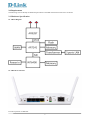
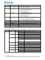
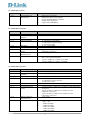
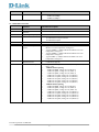
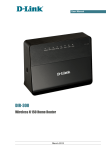
Product External Specification For Wireless N Power Line Router Model Name: DHP-1320 Rev. A1 Document Revision: 1.00 Revision History This document contains confidential proprietary information and is the property of D-Link Corporation. The contents of this document may not be disclosed to unauthorized persons without the written consent of D-Link Corporation. Rev. Date Author Reason for Changes 0.9 0.91 0.92 1.00 2010/2/8 2010/2/24 2010/4/8 2010/9/1 Webber Hsu Webber Hsu Webber Hsu Webber Hsu Initial draft Modify LED behavior Add USB First Release Contents D-Link Corporation confidential ii 1.0 SCOPE ............................................................................................................................................................................ 1 1.1 PRODUCT FEATURE....................................................................................................................................................... 1 2.0 REQUIREMENTS ........................................................................................................................................................ 3 2.1 HARDWARE SPECIFICATION .......................................................................................................................................... 3 2.1.1 Block Diagram ...................................................................................................................................................... 3 2.1.2 Hardware Interface............................................................................................................................................... 3 2.1.3 LED Indicators (LED color) ................................................................................................................................. 4 2.1.4 IEEE 802.3 Section ............................................................................................................................................... 5 2.1.5 IEEE 802.11b Section ........................................................................................................................................... 5 2.1.6 IEEE 802.11g Section ........................................................................................................................................... 5 2.1.7 IEEE 802.11n Section ........................................................................................................................................... 6 2.2 FIRMWARE SPECIFICATION ........................................................................................................................................... 7 2.2.1 Router Mod Function Table .................................................................................................................................. 7 2.2.2 Setup ..................................................................................................................................................................... 7 2.2.3 Advanced Function Configuration ........................................................................................................................ 9 2.2.4 Tools ................................................................................................................................................................... 12 2.2.5 Status .................................................................................................................................................................. 13 2.2.6 Support................................................................................................................................................................ 14 2.2.7 Background-Running Function ........................................................................................................................... 14 2.3.1 AP mode Function Table .................................................................................................................................... 14 2.3.2 Setup ................................................................................................................................................................... 15 2.3.3 Advanced Function Configuration ...................................................................................................................... 16 2.3.4 Tools ................................................................................................................................................................... 16 2.3.5 Status .................................................................................................................................................................. 17 2.3.6 Support................................................................................................................................................................ 17 2.4 SETUP UTILITY SPECIFICATION ................................................................................................................................... 17 2.5 ELECTRICAL CHARACTERISTIC ................................................................................................................................... 18 2.6 MECHANICAL REQUIREMENTS .................................................................................................................................... 18 2.7 COMPATIBILITY REQUIREMENTS ................................................................................................................................ 18 2.8 ENVIRONMENTAL REQUIREMENTS ............................................................................................................................. 18 D-Link Corporation confidential iii 1.0 Scope D-Link’s DHP-1320 is a new solution that offers 802.11n wireless speeds of up to 300 Mbps and HomePlug AV data transmission speeds of up to 200 Mbps. The combination of IEEE 802.11n and HomePlug AV standards enables connectivity of networked devices in virtually any room while also providing performance that allows for the streaming of High Definition content, fast Internet access, lag-free gaming, and VoIP. The DHP-1320 targets home users who want to wirelessly share high-quality video or quickly share large files and are restrained by conventional networking. The Wireless N PowerLine Router includes three Fast Ethernet ports and a Simple Connect button for establishing a secure PowerLine network connection in just a few seconds. It supports Shareport functionality, Router and AP mode for both HomePlug and Wireless N and is IPv6 certified. 1.1 Product Feature Power Line Interface One Powerline interface Compatible with HomePlug AV specification WAN Interface: One 10/100 Mbps Fast Ethernet port for xDSL/Cable connection LAN Interface: Three ports 10/100 Mbps Fast Ethernet switch Wireless Interface: Compatible with IEEE 802.11n specification Compatible with IEEE 802.11g specification Compatible with IEEE 802.11b specification Router Mode Functions support: WAN type support: Static IP Dynamic IP PPPoE PPTP L2TP Network Address Translation IGMP (Internet Group Management Protocol) support VPN pass through: PPTP L2TP IPSec WPS (Wi-Fi Protected Setup) Push Button PIN Wireless Security: 64/128 bits WEP WPA WPA2 Firewall: DoS prevention Stateful Packet Inspection IP/MAC Address Filtering One DMZ support. Port Forwarding Port Triggering / Special Applications support WLAN Partition D-Link Corporation confidential 1 DHCP Server. DNS Relay Web-based configuration and management Remote Management Extensive logging of gateway events Multiple SSID as well as Guest Zone support Wi-Fi WMM (Wi-Fi Multimedia) Quality of Service Multicast over Unicast Technology. UPnP support IPv6 support Shareport Support AP Mode Functions support: IGMP (Internet Group Management Protocol) support WPS (Wi-Fi Protected Setup) Push Button PIN Wireless Security: 64/128 bits WEP WPA WPA2 WLAN Partition Web-based configuration and management Extensive logging of gateway events Wi-Fi WMM (Wi-Fi Multimedia) Quality of Service Multicast over Unicast Technology. UPnP support IPv6 support D-Link Corporation confidential 2 2.0 Requirements The following sections identify the detailed requirements of the DHP-1320 Wireless N Power Line Router. 2.1 Hardware Specification 2.1.1 Block Diagram 2.1.2 Hardware Interface D-Link Corporation confidential 3 Feature Detailed Description 2.1.2.1 Power Line Interface One Powerline interface Compatible with HomePlug AV specification up to 200Mbps 2.1.2.2 WAN Interface (Internet) 2.1.2.3 LAN Interface One 10/100 Mbps Fast Ethernet port Complies IEEE 802.3u specification Support IEEE 802.3x Flow Control Support Auto Negotiation Support Auto MDI/MDIX three 10/100 Mbps Fast Ethernet port Complies IEEE 802.3u specification Support IEEE 802.3x Flow Control Support Auto Negotiation Support Auto MDI/MDIX 2.1.2.4 WLAN Interface 2.1.2.5 2.1.2.6 2.1.2.7 2.1.2.8 2.1.2.9 2.1.2.10 2.1.2.11 Reset Button Power Button WPS Button Eny Button Power Receptor USB Interface AP/Router switch Compatible with IEEE 802.11n specification Compatible with IEEE 802.11g specification Compatible with IEEE 802.11b specification Two external 2dBi Omni-direction Antennas 1 Push button for reset the device to default setting. 1 Push button for power on/off the device. 1 Push button for WPS connection 1 Push button for Power Line encryption connection 1 Receptor for the supplied power adapter. 1 USB 2.0 support shareport For AP/Router mode switch 2.1.3 LED Indicators (LED color) 2.1.3.1 LED Indicator Color Status Description Power Green/ Orange Internet Green/ Orange Power Line Green During power on process The device is power on The device is power off Internet connection is established Internet connection is not established Data transmission The link is not established The power line link is established Data transmission Wait for sync with other PLC device WLAN Green LAN Green USB Green WPS Blue Solid Orange Solid Green Light off Solid Green Solid Orange Blinking Green Light off Solid Green Blinking Green Blinking Green one time two second Light off Solid Green Blinking Green Light off Solid Green Blinking Green Light off Solid Green Light off Solid Blue Blinking Blue Light off The power line link is not established Wireless is up Data transmission Wireless is off The LAN link is established Data transmission The LAN link is down USB device is connected No USB device is connected The connection is established Waiting for other WPS device connection No WPS function is working D-Link Corporation confidential 4 2.1.4 IEEE 802.3 Section 2.1.4.1 Feature Detailed Description 10/100 BASE-TX Fast Ethernet IEEE 802.3u compliance IEEE 802.3x Flow Control support Support Full/Half Duplex operations Support Auto Negotiation Support Auto MDI/MDIX 2.1.5 IEEE 802.11b Section 2.1.5.1 2.1.5.2 2.1.5.3 2.1.5.4 2.1.5.5 2.5.5.6 2.1.5.7 2.1.5.8 2.1.5.9 Feature Detailed Description Standard Radio and Modulation Schemes Operating Frequency Channel Numbers IEEE 802.11b DQPSK, DBPSK, DSSS, and CCK Data Rate Media Access Protocol Transmitter Output Power Effective Isotropic Radiated Power Receiver Sensitivity 2400 ~ 2497MHz ISM band 11 channels for United States 13 channels for Europe Countries 14 channels for Japan 11, 5.5, 2, and 1 Mbps CSMA/CA with ACK Typical 19 dBm (+/-2dB) at 11, 5.5, 2, and 1Mbps at room temperature 25 degree C 18.0 dBm (typical) Typical Sensitivity at Which Frame (1000-byte PDUs) Error Rate = 8% at room temperature. Typical –83dBm for 11Mbps @ 8% PER Typical –89dBm for 2Mbps @ 8% PER 2.1.6 IEEE 802.11g Section 2.1.6.1 2.1.6.2 2.1.6.3 2.1.6.4 2.1.6.5 2.1.6.6 2.1.6.7 Feature Detailed Description Standard Radio and Modulation Schemes Operating Frequency Channel Numbers IEEE 802.11g BPSK, QPSK, 16QAM, 64QAM, and OFDM Data Rate Media Access Protocol Transmitter Output Power 2400 ~ 2497MHz ISM band 11 channels for United States 13 channels for Europe Countries 14 channels for Japan 54, 48, 36, 24, 18, 12, 9, and 6 Mbps CSMA/CA with ACK Typical 17 dBm (+/-2dB) at 6 to 18 Mbps at room temperature 25 degree C Typical 16 dBm (+/-2dB) at 24 to 36 Mbps at room temperature 25 degree C Typical 15 dBm (+/-2dB) at 48 to 54 Mbps at room temperature 25 degree C 16.0 (typical) 2.1.6.8 2.1.6.9 Effective Isotropic Radiated Power Receiver Sensitivity Typical Sensitivity at Which Frame (1000-byte PDUs) Error Rate = 10% –82dBm at 6Mbps –81dBm at 9Mbps –79dBm at 12Mbps –77dBm at 18Mbps –74dBm at 24Mbps D-Link Corporation confidential 5 Feature Detailed Description –70dBm at 36Mbps –66dBm at 48Mbps –65dBm at 54Mbps 2.1.7 IEEE 802.11n Section 2.1.7.1 2.1.7.2 2.1.7.3 2.1.7.4 2.1.7.5 2.1.7.6 2.1.7.7 Feature Detailed Description Standard Radio and Modulation Schemes Operating Frequency Channel Numbers IEEE 802.11n BPSK, QPSK, 16QAM, 64QAM with OFDM Data Rate Media Access Protocol Transmitter Output Power 2400 ~ 2483.5MHz ISM band 11 channels for United States 13 channels for Europe Countries 14 channels for Japan 6.5~300 Mbps CSMA/CA with ACK Typical 15dBm (+/-2dB) at MCS0 to MCS4 and MCS8 to MCS12 at room temperature 25 degree C Typical 13dBm (+/-2dB) at MCS5 and MCS13 at room temperature 25 degree C Typical 12dBm (+/-2dB) at MCS6 and MCS14 at room temperature 25 degree C Typical 8dBm (+/-2dB) at MCS7 and MCS15 at room temperature 25 degree C 8 (MCS7) (typical) 8 ( MCS15) (typical) Typical Sensitivity at Which Frame (1000-byte PDUs) Error Rate = 10% 20MHz channel spacing –82dBm at BPSK, coding rate 1/2 (MCS-0) –79dBm at QPSK, coding rate 1/2 (MCS-1) –77dBm at QPSK, coding rate 3/4 (MCS-2) –74dBm at 16-QAM, coding rate 1/2 (MCS-3) –70dBm at 16-QAM, coding rate 3/4 (MCS-4) –66dBm at 64-QAM, coding rate 2/3 (MCS-5) –65dBm at 64-QAM, coding rate 3/4 (MCS-6) –64dBm at 64-QAM, coding rate 5/6 (MCS-7) 40MHz channel spacing –79dBm at BPSK, coding rate 1/2 (MCS-8) –76dBm at QPSK, coding rate 1/2 (MCS-9) –74dBm at QPSK, coding rate 3/4 (MCS-10) –71dBm at 16-QAM, coding rate 1/2 (MCS-11) –67dBm at 16-QAM, coding rate 3/4 (MCS-12) –63dBm at 64-QAM, coding rate 2/3 (MCS-13) –62dBm at 64-QAM, coding rate 3/4 (MCS-14) –61dBm at 64-QAM, coding rate 5/6 (MCS-15) 2.1.7.8 2.1.7.9 Effective Isotropic Radiated Power Receiver Sensitivity D-Link Corporation confidential 6 2.2 Firmware Specification 2.2.1 Router Mod Function Table SETUP ADVANCED TOOLS STATUS SUPPORT Internet Virtual Server Admin Device Info Menu Wireless Settings Port Forwarding Time Logs Setup Network Settings Application Rules Syslog Statistics Advance PLC Settings Network Filter Email Settings Internet Sessions Tools USB Settings Access Control System Routing Status Website Filter Firmware Wireless Inbound Filter Dynamic DNS IPv6 Firewall Settings System Check Advanced Wireless Schedules WI-FI Protected Setup Advanced Network IPv6 Guest Zone The Web-based Configuration Interface supports browsers that certify the W3C standard. This web-based configuration interface includes the following functions: Setup Setup allows you to configure parameters for Internet connection, wire networking and wireless networking by Setup Wizard or manually configuration. Advanced (Advanced Function Configuration) Advanced Function Configuration allows you to configure advanced features such as port forwarding, virtual server, QoS Engine, firewall setting ….etc. Tools Tools provides administrators to manage the router. Status Status allows you to display the router information and status. Support To provide an online user manual that facilitates the setup. 2.2.2 Setup 2.2.2.1 Feature Detailed Description Internet Setup To set up Internet connection by using either Internet Connection Setup Wizard or Manual Internet Connection Setup. D-Link Corporation confidential 7 Feature 2.2.2.2 Wireless Settings Detailed Description Static IP Address Select this option if your ISP (Internet Service Provider) has provided you with an IP address, Subnet Mask, Default Gateway, and a DNS server address. Enter this information in the appropriate fields. Dynamic IP Address Select this option if your ISP (Internet Service Provider) provides you an IP address automatically. Cable modem providers typically use dynamic assignment of IP Address. PPPoE Select this option if your ISP requires you to use a PPPoE (Point to Point Protocol over Ethernet) connection. DSL providers typically use this option. Select Dynamic PPPoE to obtain an IP address automatically for your PPPoE connection (used by majority of PPPoE connections). Select Static PPPoE to use a static IP address for your PPPoE connection. PPTP Select this option if your ISP uses a PPTP (Point to Point Tunneling Protocol) connection and has assigned you a username and password in order to access the Internet. Select Dynamic PPTP to obtain an IP address automatically for your PPTP connection. Select Static PPTP to use a static IP address for your PPTP connection. L2TP Select this option if your ISP uses a L2TP (Layer 2 Tunneling Protocol) connection and has assigned you a username and password in order to access the Internet. Select Dynamic L2TP to obtain an IP address automatically for your L2TP connection. Select Static L2TP to use a static IP address for your L2TP connection. The wireless section is used to configure the wireless settings for the router. Wireless Network Settings This sections allows admins to setup the wireless network settings such as SSID, Wireless Channel, 802.11 Mode, Transmission Rate, Channel Width, and Visibility Status. 2.2.2.3 Network Settings Wireless Security Mode To protect your privacy you can configure wireless security features. This device supports three wireless security modes, including WEP, WPAPersonal, and WPA-Enterprise. WEP is the original wireless encryption standard. WPA provides a higher level of security. WPA-Personal does not require an authentication server. The WPA-Enterprise option requires an external RADIUS server. To configure the internal network settings of the router and also to configure the built-in DHCP Server to assign IP addresses to the computers on the local area network. Router Setting The IP address that is configured here is the IP address that you use to access the Web-based management interface. DHCP Server Setting Use this section to configure the built-in DHCP server to assign IP address to the computers on your network. Add DHCP Reservation (24 Rules) This section allows users to enter the “Computer Name”, “IP Address” and “MAC Address” manually for the PC that you desire to have the D-Link Corporation confidential 8 Feature Detailed Description router to statically assign the same IP to or choose the PC from the drop down menu which shows current DHCP clients. 2.2.2.4 2.2.2.5 PLC Settings USB Settings DHCP Client List Dynamic DHCP client computers connected to the unit will have their information displayed in the Dynamic DHCP Client Table. The table will show the Host Name, IP Address, MAC Address, and Expired Time of the DHCP lease for each client computer. Number of Dynamic DHCP Clients Show dynamic DHCP clients who are currently connecting the router. To configure PLC settings of this device and also to configure the Qos on the power line network. Network Name The Network Name allows the HomePlug devices that have the same network name in the HomePlug network to communicate with each other. Add Member Use this section to configure the HomePlug device on your network easily. Manual Add Member This section allows users to configure the HomePlug device manually. Member List HomePlug device connected to the unit will have their information displayed in the table. The table will show the Name, MAC Address, speed and Status for each device. QoS Settings This section prioritize HomePlug traffic passing through your device based on the device it is intended for by setting MAC address and the level of priority. Use this section to configure your USB port type. There are several types to choose from: Network USB, and WCN Configuration. 2.2.3 Advanced Function Configuration Feature Detailed Description 2.2.3.1 Virtual Server 2.2.3.2 Port Forwarding 2.2.3.3 Application Rules The Virtual Server option gives Internet users access to services on the LAN. This feature is useful for hosting online services such as FTP, Web, or game servers. For each Virtual Server, admins define a public port on the router for redirection to an internal LAN IP Address and LAN port. Support 24 Virtual Server List Multiple connections are required by some applications, such as internet games, video conferencing, Internet telephony, and others. These applications have difficulties working through NAT (Network Address Translation). This function is used to open multiple ports or a range of ports in the router and redirect data through those ports to a single PC on the internal network. Support 24 Port Forwarding Rules An application rule is used to open single or multiple ports on the router when the router senses data sent to the Internet on a “trigger” port or port range. An application rule applies to all computers on the internal D-Link Corporation confidential 9 Feature Detailed Description 2.2.3.4 Network Filter 2.2.3.5 Access Control 2.2.3.6 Website Filter 2.2.3.7 Inbound Filter 2.2.3.8 Firewall Settings 2.2.3.9 Advanced Wireless 2.2.3.10 Wi-Fi Protected Setup network. Support 24 Application Rules The MAC address filter section can be used to filter network access by machines based on the unique MAC addresses of their network adapter(s). It is most useful to prevent unauthorized wireless devices from connecting to your network. Support 24 MAC Filtering Rules The Access Control section allows you to control access in and out of devices on the network. Use this feature as Parental Controls to only grant access to approved sites, limit web access based on time or dates, and/or block access from applications such as peer-to-peer utilities or games. Support 24 Access Control List Website Filter is a function for admins to add the Web sites to be used for Access Control. Support 40 Website Filtering Rules Inbound Filters can be used for limiting access to a server on the network to a system or group of systems. Filter rules can be used with Virtual Server, Gaming, or Remote Administration features. Support 24 Inbound Filtering Rules The router provides a tight firewall by virtue of the way NAT works. Unless configuring the router to the contrary, the NAT does not respond to unsolicited incoming requests on any port, thereby making the LAN invisible to Internet cyberattackers. Firewall Setting This section allows admins to enable SPI (“stateful packet inspection” also known as “dynamic packet filtering”) which helps to prevent cyberattacks by tracking more state per session. It validates that the traffic passing through that session conforms to the protocol. When the protocol is TCP, SPI checks that packet sequence numbers are within the valid range for the session, discarding those packets that do not have valid sequence numbers. NAT Endpoint Filtering The NAT Endpoint Filtering options control how the router’s NAT manages incoming connection requests to ports that are already being used. Anti-Spoof Checking This mechanism protects against activity from spoofed or forged IP addresses, mainly by blocking packets appearing on interfaces and in directions which are logically not possible. DMZ Host DMZ means “Demilitarized Zone.” If an application has trouble working from behind the router, admins can expose one computer to the Internet and run the application on that computer. When a LAN host is configured as a DMZ host, it becomes the destination for all incoming packets that do not match some other incoming session or rule. If any other ingress rule is in place, that will be used instead of sending packets to the DMZ host; so, an active session, virtual server, active port trigger, or port forwarding rule will take priority over sending a packet to the DMZ host. Advanced Wireless Setup provides administrators to configure detail wireless perimeters. Wi-Fi Protected Setup is used to easily add devices to a network using a PIN or button press. Wi-Fi Protected Setup This section allows admins to enable and disable WPS. PIN Settings A PIN is a unique number that can be used to add the router to an existing D-Link Corporation confidential 10 Feature Detailed Description network or to create a new network. The default PIN may be printed on the bottom of the router. For extra security, a new PIN can be generated. 2.2.3.11 Advanced Network 2.2.3.12 IPv6 Add Wireless Station This Wizard helps you add wireless devices to the wireless network. It will either display the wireless network settings to guide you through manual configuration, prompt you to enter the PIN for the device, or ask you to press the configuration button on the device. If the device supports Wi-Fi Protected Setup and has a configuration button, you can add it to the network by pressing the configuration button on the device and then the on the router within 60 seconds. The status LED on the router will flash three times if the device has been successfully added to the network. Provide advanced network settings such as UPnP, WAN Ping, WAN Speed, and Multicast stream Enablers. UPnP This section allows admins to enable or disable UPnP which helps other UPnP LAN hosts interoperate with the router. Leave the UPnP option enabled as long as the LAN has other UPnP applications. WAN Ping If admins enable this feature, the WAN port of your router will respond to ping requests from the Internet that are sent to the WAN IP Address. WAN Port Speed The WAN speed is usually detected automatically. However, admins can select the speed manually. Multicast Stream The router uses the IGMP protocol to support efficient multicasting – transmission of identical content, such as multimedia, from a source to a number of recipients. This section allows admins to enable or disable multicast stream support. The IPv6 (Internet Protocol version 6) section is where you configure your IPv6 Connection type. Link-local Mode Link-local address is used by nodes and routers when communicating with neighboring nodes on the same link. This mode enables IPv6-capable devices to communicate with each other in the LAN side. Static IPv6 Mode Used when your ISP provides you a set IPv6 address that does not change. The IPv6 information is manually entered in your IPv6 configuration settings. You must enter the IPv6 address, Subnet Prefix Length, Default Gateway, Primary DNS Server, and Secondary DNS Server. Your ISP provides you with all of this information. DHCPv6 Mode A method of connection where the ISP assigns your IPv6 address when your router requests one from the ISP’s server. Some ISP’s require you to make some settings on your side before your router can connect to the IPv6 Internet. PPPoE Select this option if your ISP requires you to use a PPPoE (Point to Point Protocol over Ethernet) connection to IPv6 Internet. DSL providers typically use this option. This method of connection requires you to enter a Username and Password (provided by your Internet Service Provider) to gain access to the IPv6 Internet. The supported authentication protocols are PAP and CHAP. D-Link Corporation confidential 11 Feature 2.2.3.13 Detailed Description IPv6 in IPv4 Tunnel Mode IPv6 in IPv4 tunneling is the encapsulation of IPv6 packets in IPv4 packets so that IPv6 packets can be sent over an IPv4 infrastructure. 6to4 Mode 6to4 is an IPv6 address assignment and automatic tunneling technology that used to provide unicast IPv6 connectivity between IPv6 sites and hosts across the IPv4 Internet. Enable Autoconfiguration These two values (from and to) define a range of IPv6 addresses that the DHCPv6 Server uses when assigning addresses to computers and devices on your Local Area Network. Any addresses that are outside of this range are not managed by the DHCPv6 Server; these could, therefore, be used for manually configured devices or devices that cannot use DHCPv6 to obtain network address details automatically. When you selected Stateful (DHCPv6), the following options are displayed. The computers (and other devices) connected to your LAN also need to have their TCP/IP configuration set to “DHCPv6” or “Obtain an IPv6 address automatically”. Guest Zone provides a separate network zone for guest to access internet. Guest Zone Feature Detailed Description Admin 2.2.4 Tools 2.2.4.1 2.2.4.2 Time The Admin option is used to set a password for access to the Web-based management and enable Remote Management that allows admins to manage the router from anywhere on the Internet. Admin Password Enter a password for the user “admin”, who will have full access to the Web-based management interface. User Password Enter a password for the user “user”, who will have read-only access to the Web-based management interface. System Name The name of the router can be changed here. Administration Enabling Remote Management allows you to manage the router from anywhere on the Internet. Disabling Remote Management allows you to manage the router only from computers on your LAN. The Time Configuration option allows admins to configure, update, and maintain the correct time on the router’s internal system clock. Time Configuration From this section admins can set the time zone that users are in and daylight saving can also be configured to automatically adjust the time when needed. Automatic Time Configuration This section allows admins to setup the time configuration through NTP. Set The Date and Time Manually D-Link Corporation confidential 12 Feature Detailed Description This section allows admins to setup the time configuration manually or copy the setting from PC. 2.2.4.3 2.2.4.4 Syslog Email Settings Email Setting This section is used to setup the email SMTP server. Email log when FULL or on Schedule This section allows admins to setup a schedule for emailing the log. This section allows admins to manage the router’s configuration settings, reboot the router, and restore the router to the factory default settings. Restoring the unit to the factory default settings will erase all settings, including any rules that have created. The Firmware Upgrade section can be used to update to the latest firmware code to improve functionality and performance. Firmware Information Here are displayed the version numbers of the firmware currently installed in your router and the most recent upgrade that is available. 2.2.4.5 System 2.2.4.6 Firmware Firmware Upgrade This section allows admins to upgrade the firmware by uploading it from their local hard drive. Firmware Upgrade Notification Options This section enables the router to 13utomatically check whether an new firmware is released and send the information by email to admins. Clients can enter a host name to connect to the servers within the LAN, no matter what the IP address is. An Internet utility function called Ping that sends a series of short messages to a target computer and reports the results of quality of a connection. Ping Test This useful diagnostic utility can be used to check if a computer is on the Internet. It sends ping packets and listens for replies from the specific host. Enter in a host name or the IP address that you want to ping (Packet Internet Groper) and click “Ping.” 2.2.4.7 Dynamic DNS 2.2.4.8 System Check 2.2.4.9 This section allows admins to archive the log files to a Syslog Server. The Email feature can be used to send the system log files, router alert messages, and firmware update notification to a email address. Enable This section allows admins to enable or disable the email setting. Schedules Ping Result The status of your Ping attempt will be displayed in the Ping Result box. Schedules can be created for use with enforcing rules and applied to all access control rules. 2.2.5 Status Feature Detailed Description 2.2.5.1 Device Info 2.2.5.2 Logs All of your Internet and network connection details are displayed on the Device Info page. The firmware version is also displayed here. The router automatically logs (records) events of possible interest in its internal memory. If there is not enough internal memory for all events, logs of older events are deleted, but logs of the latest events are retained. The Logs option allows you to view the router logs. You can define what types of events you want to view and the level of events to view. This router also has external Syslog Server support so you can send the log D-Link Corporation confidential 13 Feature Detailed Description 2.2.5.3 Statistics 2.2.5.4 Internet Sessions 2.2.5.5 2.2.5.6 Routing Wireless 2.2.5.7 IPv6 Feature Detailed Description Menu Setup Advance Tools Status files to a computer on your network that is running a Syslog utility. The Statistics page displays all of the LAN, WAN, and Wireless packet transmit and receive statistics. The Internet Sessions page displays full details of active Internet sessions through your router. An Internet session is a conversation between a program or application on a LAN-side computer and a program or application on a WAN-side computer. This routing displays the routing details configured for your router. The wireless section allows you to view the wireless clients that are connected to your wireless router. All of your IPv6 Internet and network connection details are displayed on this page. 2.2.6 Support 2.2.6.1 2.2.6.2 2.2.6.3 2.2.6.4 2.2.6.5 Support menu tree Setup help Advance help Tools help Status help 2.2.7 Background-Running Function Feature Detailed Description 2.2.7.1 ALG 2.2.7.2 XML-Agent Application Level Gateway (ALG) Some protocols and applications require special handling of the IP payload to make them work with network address translation (NAT). ALGs for common applications are enabled by default. XML-Agent Support Yahoo Widget, Vista SideBar Gadget and Apple Dashboard Widget. 2.3.1 AP mode Function Table SETUP ADVANCED TOOLS STATUS SUPPORT Setup Wizard MAC Address Filter Admin Device Info Menu Wireless Settings Advanced Wireless Time Logs Setup PLC Settings User Limit Firmware Statistics Advance System Wireless Tools Schedule The Web-based Configuration Interface supports browsers that certify the W3C standard. This web-based configuration interface includes the following functions: D-Link Corporation confidential 14 Status Setup Setup allows you to configure parameters for Internet connection, wire networking and wireless networking by Setup Wizard or manually configuration. Advanced (Advanced Function Configuration) Advanced Function Configuration allows you to configure advanced features such as MAC Address Filter, Advanced Wireless and User Limit. Tools Tools provides administrators to manage the router. Status Status allows you to display the router information and status. Support To provide an online user manual that facilitates the setup. 2.3.2 Setup Feature Detailed Description 2.3.2.1 Setup Wizard The Setup Wizard section is used to configure the wireless settings for the device via easy wizard. 2.2.2.2 Network Settings Use this section to configure the internal network settings of your AP. Device Name(NetBIOS Name) allows you to configure this device more easily when your network using TCP/IP protocol. You can enter the device name of the AP into your web browser to access the instead of IP address for configuration. Recommend to change the device name if there're more than one D-Link devices within the subnet. 2.3.2.3 Wireless Settings The wireless section is used to configure the wireless settings for the router. Wireless Network Settings This sections allows admins to setup the wireless network settings such as SSID, Wireless Channel, 802.11 Mode, Transmission Rate, Channel Width, and Visibility Status. 2.3.2.4 PLC Settings Wireless Security Mode To protect your privacy you can configure wireless security features. This device supports three wireless security modes, including WEP, WPAPersonal, and WPA-Enterprise. WEP is the original wireless encryption standard. WPA provides a higher level of security. WPA-Personal does not require an authentication server. The WPA-Enterprise option requires an external RADIUS server. To configure the PLC settings of the device and also to configure the Qos on your HomePlug network. Network Name The Network Name allows the HomePlug devices that have the same network name in the HomePlug network to communicate with each other. Add Member Use this section to configure the HomePlug device on your network easily. Manual Add Member This section allows users to configure the HomePlug device manually. Member List HomePlug device connected to the unit will have their information displayed in the table. The table will show the Name, MAC Address, speed and Status for each device. D-Link Corporation confidential 15 Feature Detailed Description QoS Settings This section prioritize HomePlug traffic passing through your device based on the device it is intended for by setting MAC address and the level of priority. 2.3.3 Advanced Function Configuration Feature Detailed Description 2.3.3.1 MAC Address Filter 2.3.3.2 Advanced Wireless 2.3.3.3 User limit Feature Detailed Description Admin The MAC address filter section can be used to filter network access by machines based on the unique MAC addresses of their network adapter(s). It is most useful to prevent unauthorized wireless devices from connecting to your network. Advanced Wireless Setup provides administrators to configure detail wireless perimeters. Limit the connected client number. (1-32) 2.3.4 Tools 2.3.4.1 2.3.4.2 Time User Password Enter a password for the user “user”, who will have read-only access to the Web-based management interface. System Name The name of the router can be changed here. Administration Enabling Remote Management allows you to manage the router from anywhere on the Internet. Disabling Remote Management allows you to manage the router only from computers on your LAN. The Time Configuration option allows admins to configure, update, and maintain the correct time on the router’s internal system clock. Time Configuration From this section admins can set the time zone that users are in and daylight saving can also be configured to automatically adjust the time when needed. 2.3.4.3 System The Admin option is used to set a password for access to the Web-based management and enable Remote Management that allows admins to manage the router from anywhere on the Internet. Admin Password Enter a password for the user “admin”, who will have full access to the Web-based management interface. Automatic Time Configuration This section allows admins to setup the time configuration through NTP. Set The Date and Time Manually This section allows admins to setup the time configuration manually or copy the setting from PC. This section allows admins to manage the router’s configuration settings, reboot the router, and restore the router to the factory default settings. Restoring the unit to the factory default settings will erase all settings, including any rules that have created. D-Link Corporation confidential 16 2.3.4.4 Feature Detailed Description Firmware The Firmware Upgrade section can be used to update to the latest firmware code to improve functionality and performance. Firmware Information Here are displayed the version numbers of the firmware currently installed in your router and the most recent upgrade that is available. Firmware Upgrade This section allows admins to upgrade the firmware by uploading it from their local hard drive. Firmware Upgrade Notification Options This section enables the router to automatically check whether an new firmware is released and send the information by email to admins. Language Pack Information This section allows admins to change language pack by uploading it from their local hard drive. Schedules Feature Detailed Description 2.3.5.1 Device Info 2.3.5.2 Logs 2.3.5.3 Statistics 2.3.5.4 Wireless Feature Detailed Description Menu Setup Advance Tools Status 2.3.4.5 Schedules can be created for use with enforcing rules and applied to all access control rules. 2.3.5 Status All of your Internet and network connection details are displayed on the Device Info page. The firmware version is also displayed here. The router automatically logs (records) events of possible interest in its internal memory. If there is not enough internal memory for all events, logs of older events are deleted, but logs of the latest events are retained. The Logs option allows you to view the router logs. You can define what types of events you want to view and the level of events to view. This router also has external Syslog Server support so you can send the log files to a computer on your network that is running a Syslog utility. The Statistics page displays all of the LAN, WAN, and Wireless packet transmit and receive statistics. The wireless section allows you to view the wireless clients that are connected to your wireless router. 2.3.6 Support 2.3.6.1 2.3.6.2 2.3.6.3 2.3.6.4 2.3.6.5 Support menu tree Setup help Advance help Tools help Status help 2.4 Setup Utility Specification Feature Detailed Description 2.4.1 DCC 2.4.2 QRS D-Link Click’n Connect (DCC) utility for DEU 16 Languages Support Quick Router Setup (QRS) utility for DUS and DI 24 Languages Support D-Link Corporation confidential 17 2.5 Electrical Characteristic 2.5.1 2.5.2 Feature Detailed Description Power Input Power Consumption 100V ~ 240V Below 12W 2.6 Mechanical Requirements 2.6.1 2.6.2 2.6.3 2.6.4 Feature Detailed Description Length Width Height Weight 198mm 134mm 41.9mm 465.5g 2.7 Compatibility Requirements This device passes the following compatibility requirements. 2.7.1 2.7.2 2.7.3 2.7.4 Feature Detailed Description WHQL Wi-Fi IPv6 HomePlug AV Meet applicable WHQL certification requirements. Meet applicable Wi-Fi 802.11b/g/n certification requirements. Meet applicable IPv6 phaseII certification requirements. Meet applicable HomePlug AV certification requirements. 2.8 Environmental Requirements 2.8.1 2.8.2 2.8.3 2.8.4 Feature Detailed Description Operating Temperature Conditions Non-Operating Temperature Conditions Operating Humidity conditions Non-Operating Humidity Conditions The product is capable of continuous reliable operation when operating in ambient temperature of 0 ℃ to +40℃. Neither subassemblies is damaged nor the operational performance be degraded when restored to the operating temperature after exposing to storage temperature in the range of -20 ℃ to +65 ℃. The product is capable of continuous reliable operation when subjected to relative humidity in the range of 10% and 90% non-condensing. The product is not be damaged nor the performance be degraded after exposure to relative humidity ranging from 5% to 95% non-condensing D-Link Corporation confidential 18