1
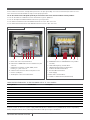
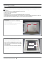
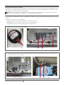
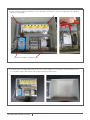
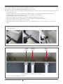
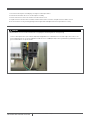
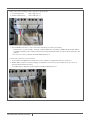
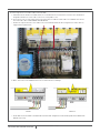
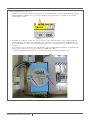
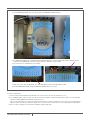
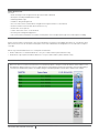
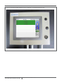
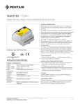
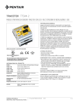
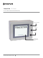
TraceTek TT-TS12
TT-TS12 Panel Installation Instructions
Front Panel USB port
Door Latch
Buzzer
12” Display and
Interactive Touch
Screen
THERMAL BUILDING &
INDUSTRIAL HEAT TRACING SOLUTIONS
EN-TraceTekTTTS12-IM-H80856 01/15
1 / 16
Description
Please read these instructions carefully and keep them in a safe place (preferably close to the TT-TS12-Panel) for future reference.
These instructions must be followed carefully to ensure proper operation.
The TT-TS12-Panel has been designed specifically for use with TraceTek sensor interface modules and relay modules.
See the TT-TS12 Data Sheet H80617 for further information on system capabilities.
See the TT-TS12 Operation Manual H80760 for details on system operation.
See the TTSIM-1 Installation Instructions H56830 for details on sensor cable connection.
See the TTSIM-1A Installation Instructions H57338 for details on sensor cable connection.
Figure 1: Interior of Door
a
b
Figure 2: Interior of Enclosure
c d e
f
a. Buzzer with connector/terminal block
b. RS232 Port to ADAM-4522 Converter and Host Port, with
connector
c. RS485 Port to Field Devices (SIMs, NRMs, Smart
Gateway, etc.), with connector
d. USB Ports with extension cable to front panel socket
e. Ethernet / LAN ports
f. 24 VDC power connection terminal block
g
h i jk
l
m
n
g. ADAM-4522 Converter and ADAM-4069 relay module
(stacked)
h. LEAK Summary Relay Terminal Block
i. TROUBLE Summary Relay Terminal Block
j. Field Port RS-485 Terminal Block
k. Host RS-485 Terminal Block
l. Power Supply
m.Mains Power Terminal Block
n. TTSIM-1 or TTSIM-1A units (maximum of 4)
These Instructions apply to the following set of TT-TS12-Panels:
Catalog NumberPart Number
Description
TT-TS12-Panel-0
P000001486
Enclosure mounted TT-TS12 with no SIMs
TT-TS12-Panel-S1-1
P000001487
Enclosure mounted TT-TS12 with 1 TTSIM-1
TT-TS12-Panel-S1-2
P000001488
Enclosure mounted TT-TS12 with 2 TTSIM-1
TT-TS12-Panel-S1-3
P000001489
Enclosure mounted TT-TS12 with 3 TTSIM-1
TT-TS12-Panel-S1-4
P000001490
Enclosure mounted TT-TS12 with 4 TTSIM-1
TT-TS12-Panel-S1A-1
P000001491
Enclosure mounted TT-TS12 with 1 TTSIM-1A
TT-TS12-Panel-S1A-1
P000001492
Enclosure mounted TT-TS12 with 2 TTSIM-1A
TT-TS12-Panel-S1A-1
P000001493
Enclosure mounted TT-TS12 with 3 TTSIM-1A
TT-TS12-Panel-S1A-1
P000001494
Enclosure mounted TT-TS12 with 4 TTSIM-1A
All panels include: TT-TS12 Screen, power supply, ADAM-4522 (RS232-to-RS485 Converter), ADAM-4069 (8 channel relay module),
buzzer, front panel USB extension, field wiring terminal blocks and space for up to 4 TTSIM units.
THERMAL BUILDING &
INDUSTRIAL HEAT TRACING SOLUTIONS
EN-TraceTekTTTS12-IM-H80856 01/15
2 / 16
Installation items (not supplied)
• Wall fasteners for surface mounting (four screws) appropriate to the wall surface material
• (Optional) TT-TS12 TRIM FLANGE Part Number P000000780 (available for semi-flush mounting of the TT-TS12-Panel)
Tools required:
• Drills and chassis punch for electrical conduit or cable gland entries into TT-TS12-Panel at desired locations
• Center punch
• Phillips (cross-head) screwdriver
• Small flat-head screwdrivers for terminal block connections
• Large flat head screwdriver (or coin) to operate door latch
• Wire cutter and stripper for field wiring connections
• Long handle 4mm T-Bar Allen wrench
Storage:
Keep the TT-TS12-Panel in a dry place prior to installation to avoid possible damage to internal components
TT-TS12-Panel General Information:
Power Requirement
100 to 240 Vac; 50/60 Hz (A separate 15 Amp Branch Circuit with dedicated Circuit Breaker is required)
Weight
11.8kg (26.0 lb) (typical with 4 SIM’s installed)
Dimensions (W x H x D)
431.8 mm x 330.2 mm x 152.4 mm (17.0 in x 13.0 in x 6.0 in)
Power consumption 40 W (typical with 4 SIM’s installed)
Built-in relays 3 SPDT Pre-assigned (Buzzer Control, LEAK, and TROUBLE); 1 SPST Pre-assigned (Watchdog)
1 SPDT; 3 SPST User Programmable Relays
Additional channel specific relays available if TTSIM-1A units are installed
Rating: 5 A at 250 Vac or 5 A at 24 Vdc
External Relays:
Expandable to 320 user programmed relays using TT-NRM-BASE and TT-NRM-2RO modules
Storage temperature –20°C to 60°C (-4°F to 140°F)
Operating temperature -20°C to 60°C (-4°F to 140°F)
Ingress Protection
NEMA 1; IP 10
Approvals and Certifications: All internal components are UL Listed or Recognized. Panel is built and approved to UL 508A Standard.
THERMAL BUILDING &
INDUSTRIAL HEAT TRACING SOLUTIONS
EN-TraceTekTTTS12-IM-H80856 01/15
3 / 16
Installing the TT-TS12-Panel
WARNING:
Ignition hazard. Do not mount the TT-TS12-Panel unit in a hazardous location. The TT-TS12-Panel must be in an ordinary area. Choose
an office or control room location indoors where the TT-TS12-Panel will be protected from the elements and temperature extremes
Note: The TT-TS12-Panel is an electronic unit. During installation, take the following precautions to avoid damage to its electronic
components:
• Store the TT-TS12-Panel in its cardboard shipping box until ready to install
• Handle with care, avoid mechanical damage.
• Keep the electronics dry
• Avoid exposure to static electricity. Use personal grounding strap in high static environments
• Avoid contamination with metal filings, liquids, or other foreign matter. Use caution when drilling or punching holes for conduit entry
• Do not remove the protective film from the computer screen on the front of the unit until ready for use
Mounting Options: The TT-TS12-Panel is designed to be
mounted on a vertical wall surface or recess mounted partially
into the interior of the wall.
There are four mounting holes on the back of the TT-TS12Panel enclosure located as indicated below:
11.4'
(290 mm)
15.46'
(393 mm)
0.31' dia.
(8 mm)
4 places
The TT-TS12 is also configured for partial recess mounting
using the TT-TS12 TRIM FLANGE (P/N P000000780).
The Trim Flange is usually framed in place with wood or
aluminum studs prior to completing the wall finished surface.
Nail or screw holes are provided in the side walls of the Trim
Flange. These holes utilize the four flat head screws included
with the Trim Flange.
The four holes in the back of the trim flange are aligned with
the holes in the back of the TT-TS12-Panel. These holes are
threaded and utilize the four pan head screws included with
the Trim Flange.
THERMAL BUILDING &
INDUSTRIAL HEAT TRACING SOLUTIONS
EN-TraceTekTTTS12-IM-H80856 01/15
17.36'
(441 mm)
0.27' dia. (6.9 mm)
4 places
5.75'
(146 mm)
4 / 16
Cable Gland and Conduit Entries
The primary cable entry surface is the bottom edge of the TT-TS12-Panel enclosure. Alternate entry points may be appropriate for some
installations. It is the responsibility of the installer to note internal clearance and choose standard entry points such that the wire and
cable routing do not interfere with the internal components.
Note: Remove the back plane assembly and wire harness prior to drilling or punching holes for cable glands or conduit entries
because of the risk of damage to the components or contamination due to metal filings.
Removing the back plane assembly and wire harness:
1. The back plane assembly and wire harness are designed to be removed as a single unit with a minimum of disruption to the internal
wiring.
2. At the rear of the TS12 touch screen, disconnect:
a. 24VDC Power Connection terminal block (may be secured by small screws)
b. RS485/RS422 Connector (may be secured by small screws or finger tighteners)
c. RS232 Connector (may be secured by small screws or finger tighteners)
3. Disconnect the connector on the back of the buzzer
3
2c2b
2a
4. Unsnap (open) two wire harness holders on the door and two wire harness holders on the left side of the enclosure tub. Gently
remove the wire harness from the holders.
Door wire harness holders
THERMAL BUILDING &
INDUSTRIAL HEAT TRACING SOLUTIONS
EN-TraceTekTTTS12-IM-H80856 01/15
Enclosure wire harness holders
5 / 16
5. Remove four bolts (4 mm Allen head) that secure the back plane assembly to the enclosure. A long handle 4 mm T-bar Allen
Wrench is recommended.
Back plane assembly securing bolt locations
6. Lift the back plane assembly and wire harness out of the enclosure and place on a clean surface. The TT-TS12 touch screen
itself, the buzzer and the USB extension cable remain mounted on the door interior.
THERMAL BUILDING &
INDUSTRIAL HEAT TRACING SOLUTIONS
EN-TraceTekTTTS12-IM-H80856 01/15
6 / 16
Cable Gland and Conduit Entries
There are three categories of cable connections. See Figure 2 for reference.
A.Mains power – generally positioned in the lower right corner of the enclosure
B.Network connections – (all of the following are optional and may not be relevant for a specific installation). Positioned on right half of
enclosure bottom surface
a. RS485 twisted pair cable to any external SIM units; TT-NRM relay units; Smart Gateways; RTU radios; Fiber Optic Modem
b. RS485 twisted pair cable to any host BMS, PLC, or DCS system using serial communications
c. Up to two Ethernet cable connections to local LAN
d. Dry contact relay pairs from summary relays for LEAK, TROUBLE and Watchdog alarm signals
e. Dry contact relay pairs from user programmable contacts 5 through 8 of built in ADAM 4069 module
f. Dry contact relay pairs from TTSIM-1A units. (if installed)
C.Leader Cables to TraceTek sensor cable or probe circuits - generally positioned to the center or left side of the enclosure bottom
surface.
1. Mark the desired conduit or gland entry locations. Use a center punch, pilot drill, step drill and chassis punch to create the
desired entry points:
2. Install cable gland and conduit after holes are created. See figure below.
LEADER
CABLES
NETWORKS
& RELAYS
MAINS
POWER
Figure 3. Example of completed conduit installation
3. Clean all metal chips and debris from enclosure.
THERMAL BUILDING &
INDUSTRIAL HEAT TRACING SOLUTIONS
EN-TraceTekTTTS12-IM-H80856 01/15
7 / 16
Re-install Back Plane Assembly and Wire Harness
1. Re-install the back plane assembly by reversing the removal procedures.
2. Reinstall the four bolts that secure the back plane assembly.
3. Restore wire harness connectors on back of TT-TS12 touchscreen.
4. Slip wire harness into wire harness holders on door and left side of enclosure. Snap wire harness holders closed.
5. Check for interference by carefully opening and closing the door and adjust wire harness position if necessary
Making Connections:
CAUTION:
1. Assure branch circuit to TT-TS12 has been de-energized prior to working with line voltage wiring.
Connect mains power wires (100- 240 Vac 50/60 Hz) and ground to the terminal blocks in the lower right corner. There is no
preferred position for line or neutral. Maximum conductor size is 10 AWG (4.5 mm). Connect ground wire (if provided) to yellow/
green terminal block. See picture below.
THERMAL BUILDING &
INDUSTRIAL HEAT TRACING SOLUTIONS
EN-TraceTekTTTS12-IM-H80856 01/15
8 / 16
2. Make connections to summary relays if required. See picture below.
a. Leak Summary Relay (NO: 1 COM: 2 NC: 3 )
b. Trouble Summary Relay (NO: 4 COM: 5 NC: 6 )
3. Connections to External SIM Network. See picture below.
a. External Modbus slave devices can be connected via twisted pair at terminals 7 (+) and 8 (-)
i. Permitted devices include: TTSIM-1; TTSIM-1A; TTSIM-2; ADAM-4069 relay modules; ADAM-4051 digital input modules;
TT-NRM Relay Modules; Emerson/Rosemount Smart Gateway; GE-MDS RTU radios (or equivalent); RS-485-to-fiber optic
modems
ii. All slave devices must respond to 9600 baud ModbusRTU protocol.
4. Connections to Host Port. See picture below.
a. 2-wire RS485 serial ModbusRTU communications to host computers is supported at terminal 9 (+) and 10 (-)
b. Modbus address, baud rate, stop bits and parity, are adjustable to match the host system requirements. (See TT-TS12
Operation Manual H80760 for details)
c. See Modbus Register Map for detailed listing of all available mapped parameters
THERMAL BUILDING &
INDUSTRIAL HEAT TRACING SOLUTIONS
EN-TraceTekTTTS12-IM-H80856 01/15
9 / 16
5. Connecting sensor circuit leader cables to internal SIMs
a. A maximum of four TTSIM-1 or TTSIM-1A units are installed within the TT-TS12-Panel enclosure. Each TTSIM unit is
designed to monitor one sensor cable circuit or one sensor probe circuit.
b. Each sensor circuit is connected to the TS12 enclosure with a 4-conductor leader cable. The standard color code for
TraceTek leader cables is RED-GREEN-YELLOW-BLACK
c. Remove the snap-on wire duct covers and use the vertical and horizontal wire duct to organize the leader cables as
suggested in the photo below.
d. Make connections to the individual SIM circuits as indicated in these drawings
TTSIM-1TTSIM-1A
e. Detailed discussion of TTSIM-1 and TTSIM-1A installation and configuration can be found in publications H56830 and
H57338 respectively.
THERMAL BUILDING &
INDUSTRIAL HEAT TRACING SOLUTIONS
EN-TraceTekTTTS12-IM-H80856 01/15
10 / 16
6. Optional Additional Relay Connections
a. TTSIM-1A units have a built in Form-C alarm relay that can be configured to indicate LEAK; LEAK or TROUBLE; or LEAK,
SERVICE NEEDED or TROUBLE. The access to these individual relays is via Terminals 10,11 and 12 on each installed
TTSIM-1A unit, see below.
b. The ADAM-4069 module has 8 relays. The first three of these are pre-assigned for buzzer control, summary LEAK and
summary TROUBLE. The fourth relay is a watchdog contact that switches to the alarm position if the ADAM-4069 fails to
detect communications activity on the RS-485 external device buss. (Lack of activity indicates loss of power or a frozen
computer).
The remaining 4 relays are available as user programmable relays (see H80760 Operation Manual for set-up options and
details). Physical connections to the relays are made at the ADAM-4069 module
i. Remove the ADAM-4522 by loosening two screws and temporarily disconnecting the RS232 connector.
THERMAL BUILDING &
INDUSTRIAL HEAT TRACING SOLUTIONS
EN-TraceTekTTTS12-IM-H80856 01/15
11 / 16
ii. Lift the ADAM-4522 module out of the way to expose the ADAM 4069 module beneath.
iii.The ADAM-4069 module has 4 available Form-A (SPST) Normally Open relays available and 1 Form-C (SPDT) terminal
strips on the top and bottom connector. Relays 4,5 and 6 are Form-A; relay 7 is Form-C
iv.The connectors are removable for easier wiring.
v. Make relay connections as appropriate. The watchdog signal is between RL3 NO and RL3 COM.
vi.Reinstall ADAM-4522 module on top of ADAM-4069 module and secure screws.
7. Ethernet Connections
a. The TT-TS12 has two RJ-45 Ethernet/LAN connector sockets on the rear of the TT-TS12 touch screen.
b. Use standard network cables to connect the TT-TS12 to the local LAN for: email alarm notification, remote screen viewing and
operation via VNC, Modbus/TCP and future network services.
c. There are no terminal blocks or LAN connections on the back plane, so make the Ethernet connections the last field wiring step
and leave sufficient slack to run from the conduit entries to the rear of the TT-TS12 touchscreen as mounted on the door panel.
d. Take care when closing the enclosure door to avoid pinching the LAN cable.
THERMAL BUILDING &
INDUSTRIAL HEAT TRACING SOLUTIONS
EN-TraceTekTTTS12-IM-H80856 01/15
12 / 16
8. Spare USB connection
a. One USB port is permanently routed to the USB socket on
the front of the TT-TS12-Panel enclosure. The front panel
USB port is used for software updates, data base back-up,
loading images or temporary connection of a mouse or
keyboard during set-up and commissioning. A second USB
socket is available on the rear of the TT-TS12 touchscreen
and is normally not used. However the second USB port is
fully functional and can be used if circumstances require a
second USB connection. For instance a wireless keyboard/
mouse dongle can be inserted in the spare USB socket
while a USB thumb drive is inserted in the front panel
socket.
USB Ports
THERMAL BUILDING &
INDUSTRIAL HEAT TRACING SOLUTIONS
EN-TraceTekTTTS12-IM-H80856 01/15
Ethernet Ports
13 / 16
Final Inspection:
Check for:
• No metal filings or other foreign materials present (vacuum or blow out)
• Back plane assembly hold down bolts are tight
• Mounting hardware tight
• Conduit or cable glands tightened
• All screw connections at terminal blocks snug (do not over tighten smaller screw terminals)
• All wires routed such that the door opens and closes freely
• All wire duct covers replaced
• Leader cables from sensor circuits identified
• Generally neat and organized appearance
• Fuses installed in terminal block fuse holders at mains power connection point (lower right corner of back plane assembly)
Apply power:
Ensure that fuse holders at mains power connection terminal block are properly seated. Apply mains power at circuit breaker panel.
(Note that the fuses in the TT-TS12-Panel mains power connection terminal block are designed to act as local disconnect for panel
servicing).
Observe any installed TTSIM units for successful power on indications:
• TTSIM-1 indication is a red LED that blinks once every 10 seconds to indicate power and CPU activity
• TTSIM-1A has a green power on LED that blinks once every 5 seconds to indicate power and CPU activity.
Close and secure the Door Latch:
Observe the front screen of the TT-TS12 touchscreen for boot-up sequence. This process will take about 1 minute and the screen
may go dark or appear to pause for several seconds from time to time during a normal start-up. Proper start up is indicated by a
screen like that shown below, however the number and type of TTSIM may be different than what is shown in this example.
THERMAL BUILDING &
INDUSTRIAL HEAT TRACING SOLUTIONS
EN-TraceTekTTTS12-IM-H80856 01/15
14 / 16
See the TT-TS12 Operation Manual H80760 for system configuration, set-up and operating instructions.
THERMAL BUILDING &
INDUSTRIAL HEAT TRACING SOLUTIONS
EN-TraceTekTTTS12-IM-H80856 01/15
15 / 16
WWW.PENTAIRTHERMAL.COM
NORTH AMERICA
Europe, Middle East, Africa
Asia Pacific
Latin America
Tel:+1.800.545.6258
Fax:+1.800.527.5703
Tel:+1.650.216.1526
Fax:+1.650.474.7215
[email protected]
Tel:+32.16.213.511
Fax:+32.16.213.603
[email protected]
Tel:+86.21.2412.1688
Fax:+86.21.5426.2937
[email protected]
Tel.:+1.713.868.4800
Fax:+1.713.868.2333
[email protected]
Pentair and TraceTek are owned by Pentair or its global affiliates. All other trademarks are the property of their respective owners. Pentair reserves the
right to change specifications without prior notice.
© 2015 Pentair.
THERMAL BUILDING &
INDUSTRIAL HEAT TRACING SOLUTIONS
EN-TraceTekTTTS12-IM-H80856 01/15
16 / 16