1
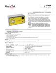
TraceTek TTSIM-1A
TraceTek Sensor Interface Module with Relay Installation/OPERATION Instructions
General Information
Please read these instructions and keep them in a safe place.
These instructions must be followed carefully to ensure proper
operation.
The TTSIM-1A has been designed for use with TraceTek sensing
cables, point sensors and normally open, dry contact devices
(float switch, pressure or vacuum switch, optical probe with
adapter, limit switch, etc.). Up to 150 m (500 ft) of sensor cable can
be monitored by the TTSIM-1A. Contact factory for information
regarding longer monitoring distance.
The TTSIM-1A is designed for installation in ordinary (nonhazardous) areas. The TTSIM-1A has five small LED’s to indicate
power, status and communications activity, as well as a relay with
SPDT contacts. The TTSIM-1A can be used as a stand-alone leak
detection alarm, or connected to a host system (TraceTek TTDM128, computer, or control automation system) via simple, twisted
pair RS-485 serial communication wiring.
Approvals and Certifications
Tools Required
TYPE NM
• Small flat blade screwdriver
• Small needle nose pliers
• Tools to mount DIN rail or enclosure
General Signaling Equipment
76LJ
Installation Items (not supplied)
• 35 mm DIN rail mounting strip (for wall mounts or interior of
large control cabinets) and attachment hardware.
Only AC versions are UL listed and VDE Certified.
For DC models use a Listed Class 2 Power Supply.
• TT-RS485 power and telemetry jumper cable.
Product Information
TTSIM-1A
22 to 26 Vac, 50/60 Hz, 3 W (SELV level for Europe)
TTSIM-1A-120
92 to 132 Vac, 50/60 Hz, 3 W
TTSIM-1A-230
216 to 253 Vac, 50/60 Hz, 3 W
TTSIM-1A-12VDC
12 Vdc +/- 10% 2W
TTSIM-1A-24VDC
24 Vdc +/- 10% 2W
Relay contacts
Form C (SPDT), 250 Vac/30 Vdc at 2 Amps maximum
(30 V SELV level for Europe)
Installation categories
Overvoltage Category II
Pollution Degree 2
Storage
Keep the TTSIM-1A modules in a dry place prior to installation.
Avoid damage to components.
Additional Items
An agency-approved zener barrier must be used where sensing
cable connected to the TTSIM-1A will be located in Class1 Div 1
(Zone 0 or 1 in Europe) Hazardous Locations.
Storage temperature
–18°C to 60°C (0°F to 140°F)
Operating temperature
0°C to 50°C (32°F to 122°F)
Enclosure
NEMA 1; IP20 (NEMA 4X / IP 56 with optional enclosure)
THERMAL BUILDING &
INDUSTRIAL HEAT TRACING SOLUTIONS
• Optional TTSIM-ENC-4X-OUTDOORS environmental enclosure
for outdoor or corrosive environments, or TTSIM-ENC-4XINDOORS enclosure with clear cover for indoor, non-corrosive
environments.
EN-TraceTekTTSIM1A-IM-H57338 01/15
1/6
Installing the TTSIM-1A
Note: To avoid damage to the TTSIM-1A, store the unit in it’s
packaging until ready to install.
Selecting the mounting position
Choose a location where the module will be protected from the
elements, temperature extremes or heavy vibration. The TTSIM-1A
is designed to be snapped onto standard 35 mm DIN rail. Existing
electrical or instrumentation cabinets with spare rail space make
good mounting locations. It is also possible to install a small section
of DIN rail directly on a wall or cabinet surface and mount the
TTSIM-1A in any location as long as it does not create a tripping
hazard or expose the TTSIM-1A to impact damage. The TTSIM1A should be mounted within 1200 m (4000 ft) wire run from the
controlling TTDM-128 or control system host. Contact the factory
for methods to increase the wire run distance beyond 1200 m.
Important: The TTSIM-1A is an electronic unit. Take
the following precautions to avoid damage to electronic
components:
• Handle with care and avoid mechanical shock and impact.
• Keep dry.
• Avoid exposure to static electricity by touching a nearby
piece of grounded equipment or water pipe prior to
handling the TTSIM-1A.
• Avoid contact with metal filings, grease, pipe dope and
other contaminants.
Mounting the TTSIM-1A module (without NEMA 4X Enclosure – Figure 1)
• Secure a sufficient length of DIN rail to the desired mounting
surface, or locate an existing DIN rail with sufficient space to
install the TTSIM-1A.
• Remove the TTSIM-1A from it’s packaging and snap onto the
DIN rail with the release tab towards the bottom.
TRACETEK
35 mm
DIN rail
Release tab
Figure 1. DIN rail mount
Mounting the TTSIM-1A module in the optional NEMA 4X Enclosure – Figure 2
• Plan conduit alignment and drill holes as necessary.
• A typical outdoor or harsh environment installation will require
three holes in the TTSIM-ENC: one for inbound power and
telemetry, one for outbound power and telemetry and one for
the sensor cable leader. See Figure 2.
• Secure the TTSIM-ENC to any convenient vertical surface using
the four corner mounting holes and hardware suitable for the
selected surface.
• Rough-in conduit as required and pull the cables for power and
telemetry. Leave approximately 20 cm (8 in) for connection to
TTSIM-1A terminals. Pull in the sensor circuit leader cable.
TRACETEK
• In order to provide maximum electrostatic discharge protection,
and to be CE compliant, the DIN rail must be grounded.
Note: Rough-in and final connections do not have to be completed
at the same time, however make sure to replace the cover and
tighten the cover screws if the enclosure will be left in a partially
installed condition overnight or longer.
Figure 2. NEMA 4X enclosure
THERMAL BUILDING &
INDUSTRIAL HEAT TRACING SOLUTIONS
EN-TraceTekTTSIM1A-IM-H57338 01/15
2/6
Power Supply Options
The TTSIM-1A has several power supply options available.
Depending on the version being installed and local regulations,
the wiring requirements may vary. In all cases, be sure that each
TTSIM-1A receives supply voltage from one and only one source.
Important: Observe polarity markings when using 12 Vdc or 24
Vdc versions.
Connections for Power and Telemetry
TTSIM-1A communicates all alarm and status messages via RS-485
twisted pair telemetry. Two of the four conductors in the power/
telemetry cable are used for telemetry and the other two wires may
be used to provide the supply voltage. Alternatively, separate wiring
may be used for the supply voltage, as shown in Figure 3.
Power Cable
Communication Cable
For all TTSIM-1A modules except the last one, there will be an incoming cable (from the TTDM-128 or other host system) and an
outgoing cable (to the next TTSIM-1A).
• Strip a sufficient amount of the jacket insulation and shielding
to expose about 2.5 cm (1 in) of the four wires.
• Strip the primary wires to expose approximately 6 mm (1/4 in) of
conductor and make the following connections: (see Figure 3)
Terminal
Color
Item
13
—
Shield Drain Wire
14
Black
RS-485 (–)
15
Red
RS-485 (+)
16
—
Shield Drain Wire
17
Black
RS-485 (–)
18
Red
RS-485 (+)
21
Green
AC/DC Supply
22
White
AC/DC Supply
23
[Green]
AC/DC Supply
24
[White]
AC/DC Supply
[Shielded twisted pair
from TTDM-128, Host,
or previous TTSIM]
Figure 3. Power and Telemetry Connections
[Shielded twisted pair
to next TTSIM]
From source or
previous TTSIM*
[To next TTSIM]
* Power supply voltage must be within range specified on TTSIM-1A label.
Items in square brackets [ ] are optional. When using TraceTek TTRS485 power and telemetry cable for power supply distribution,
follow the color codes indicated in brackets.
Connections for Alarm Relay
The software programmable TTSIM-1A relay contacts may be used
for local or remote annunciation, to control a valve or other device,
or for connection to a control automation system contact input.
The relay can be programmed to alarm on leak only; on either
leak or fault; or on leak, fault, or service required. The relay can
also be programmed to be ON (coil energized) or OFF (coil deenergized) to signal an alarm (see table below). The relay can be
programmed using either a TTDM-128 or a PC running TraceTek
TT-SUPERVISOR software.
Programmed
Alarm State
On (default)
Alarm Condition
No alarms
Alarm
open
closed
closed
open
open
closed
Alarm
closed
open
Loss of power
closed
open

Loss of power
Off
No alarms

Status at Terminals
10-11
11-12
closed
open
THERMAL BUILDING &
INDUSTRIAL HEAT TRACING SOLUTIONS
10
11
12
Figure 4. Alarm Relay Connections (shown in power off condition)
EN-TraceTekTTSIM1A-IM-H57338 01/15
3/6
Place the End of Line Jumper in the correct position
If the TTSIM-1A will be connected to a host for communication, it
is necessary to set the End of Line Jumper in the correct position
as follows:
• On the last TTSIM-1A in the circuit, place the jumper as shown
in Figure 5a.
• On all other TTSIM’s in the circuit, place the jumper as shown in
Figure 5b.
Figure 5a. End of Line Jumper for last TTSIM-1A
Figure 5b. End of Line Jumper for all other TTSIM’s
Leader Cable Connections for Sensor
The TTSIM-1A can be used with any of the TraceTek family of sensors
including: TT1000, TT3000, TT5000 and TT5001 cables. Connect the
TraceTek leader cable to the TTSIM-1A as shown in Figure 6.
Color
1
Red
2
Green
3
Yellow
4
Black
Item
Red / Green Sensor Cable Loop
Yellow / Black Sensor Cable Loop
Red
Green
Yellow
Black
Terminal
Figure 6. Sensing Cable Connections
THERMAL BUILDING &
INDUSTRIAL HEAT TRACING SOLUTIONS
EN-TraceTekTTSIM1A-IM-H57338 01/15
4/6
Operating Instructions
Network Address Assignment
If the TTSIM-1A will be used in a TraceTek network, each module
in a TraceTek network must have a unique address in the range
001 to 127. All TTSIM-1A units are shipped from the factory with
their network address pre-set to a value above the range of valid
addresses, in order to prevent communication conflicts during
system startup and configuration. Each TTSIM must therefore be
configured to a unique address before it can communicate with the
TTDM-128 or other host.
To set the TTSIM-1A network addresses, repeat the following
procedure for each TTSIM-1A. Perform the complete procedure
one module at a time:
• Place the TTSIM-1A configuration jumper in the CFG position, as
shown in Figure 7a.
• Using the TTDM-128 or host system, assign the new TTSIM-1A
address (refer to the TTDM-128 User Manual, H56853).
• Place the configuration jumper in the normal operating position,
as shown in Figure 7b, or remove it completely (the jumper is
not required in normal operation).
• Write the address in the space provided on the TTSIM-1A cover.
Figure 7a. Configuration Jumper in Configuration Position
Figure 7b. Configuration Jumper set for Normal Operation
Other configuration settings
The TTSIM-1A has a number of configurable settings, including
relay mode and operations and leak sensitivity. Refer to the TTDM128 User Manual (H56853) for details on how to change these
configurations.
THERMAL BUILDING &
INDUSTRIAL HEAT TRACING SOLUTIONS
EN-TraceTekTTSIM1A-IM-H57338 01/15
5/6
Maintenance and Troubleshooting
No user maintenance is required! There are no user adjustments or calibrations that can be performed in the field.
Each TTSIM-1A is tested and calibrated at the factory. An
operating TTSIM-1A runs a continuous self check routine and
reports any discrepancies to the TTDM-128 or host computer.
If the TTSIM-1A or the network wiring fails in such a way that
the TTSIM-1A cannot communicate with the host, then the host
reports the failure as a communications failure.
Status Indicators
There are 5 LED’s on the TTSIM-1A circuit board to indicate:
power, communications (RX = inbound and TX = outbound), sensor
status (leak detected and trouble). See Figure 8.
The green Power LED will be ON and will blink once every 5
seconds when the TTSIM-1A is powered and fuctioning correctly.
Table 1 lists various sensor status conditions and possible
corrective actions. Table 2 lists communication status conditions
(applicable when the TTSIM-1A is used in a network system).
RX (Yellow)
TX (Yellow)
Leak (Red)
Service (Yellow)
Power (Green)
TRACETEK
Figure 8 TTSIM-1A LED locations
Table 1. TTSIM-1A LED operational status indications
LEAK
SERVICE
FLASH
INDICATION
Leak detected. Check sensor for leak or spill.
ON
Leak alarm has been reset by operator but the leak condition still exists
FLASH
The sensor needs servicing. Check sensor and leadwires/jumpers for continuity or contamination.
Table 2. TTSIM-1A communication status indications (only active if connected to a network)
TX
RX
INDICATION
FLASH
FLASH
Unit is communicating normally with TTDM-128 or host.
OFF
FLASH
Unit is receiving communication from TTDM-128 or host, but is not responding.
OFF
ON
RS-485 communication wires are reversed
OFF
OFF
Unit is not communicating with TTDM-128 or host.
WWW.PENTAIRTHERMAL.COM
NORTH AMERICA
Europe, Middle East, Africa
Asia Pacific
Latin America
Tel:+1.800.545.6258
Fax:+1.800.527.5703
Tel:+1.650.216.1526
Fax:+1.650.474.7215
[email protected]
Tel:+32.16.213.511
Fax:+32.16.213.603
[email protected]
Tel:+86.21.2412.1688
Fax:+86.21.5426.2937
[email protected]
Tel:+1.713.868.4800
Fax:+1.713.868.2333
[email protected]
Pentair and TraceTek are owned by Pentair or its global affiliates. All other trademarks are the property of their respective owners. Pentair reserves the
right to change specifications without prior notice.
© 2003-2015 Pentair.
THERMAL BUILDING &
INDUSTRIAL HEAT TRACING SOLUTIONS
EN-TraceTekTTSIM1A-IM-H57338 01/15