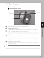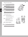
1
e-drive
User’s manual
Sweden
version 200701
Foreword
Thank you for purchasing the e-drive. Generally speaking, riding in a wheelchair incurs the possible risk
of personal injury or damage to the wheelchair from improper use or due to road surface and traffic
conditions. Depending on the type or extent of the disabilities of the user, it might be very dangerous to
travel unaccompanied. Before using the wheelchair, be sure that not only the user, but also the
assistant, has read this manual thoroughly to ensure safe and comfortable use.
Symbols Used in This Manual
Items concerning proper handling are indicated with the following symbols.
WARNING
Indicates that misuse may lead to fatal or severe injury.
CAUTION
Indicates that misuse may lead to injury or material damage.
NOTE
Indicates proper operation and key points for inspection and maintenance.
Indicates it is necessary to be accompanied by an assistant.
Indicates things you must not do.
Other Precautions
• This product is to be used as an electric propulsion unit for a wheelchair. Do not use it for any other application.
• As a wheelchair for physically handicapped people, the legal status of this product is that of a pedestrian.
Therefore, make sure to adhere to the traffic rules and manners of a pedestrian.
• To ensure safe use, safety labels are affixed to this product to indicate “Danger”, “Warning”, and “Caution”.
Make sure to follow those instructions.
Delivery check
Check that all parts are in agreement with the delivery note. You must immediately
notify the carrier of any damage during transportation. Remember to keep the
packaging until the carrier has checked the goods and a settlement has been reached.
EC Declaration of Conformity.
The undersigned, representing the following manufacturer
Decon Wheel AB Org. no 556618-9006
314 22 HYLTEBRUK
SWEDEN
Herewith declares that the product
e-drive part no series MED1000, MED1050 and MED1100
Is in conformity with the provision of the following EC directive, including all
applicable amendments:
93/42 EEC Medical Device Directive- Class I
Hyltebruk 2007-01-23
Contents
Page
Delivery check
Important safety instructions
Installing e-drive
Overturn protection
Transport and disassembly
Technical specification
Area of use
Guarantee and maintenance
For safe use
Names of parts
Nickel Metal Hydride Battery
Lithium lon Battery
Operating instructions (driving ) sid 46 ändras
Operating instructions (assistant instructions )
Setting parameters
Transport and storing instructions
Maintenance and adjustment
Troubleshooting
Specifications and other information
1
2
3-5
6
7-8
9
10
11-12
13-19
20-21
22-32
33-43
44-50
51-52
53
54-56
57-62
63
64-67
e-drive
Delivery check
Check all parts are in agreement with the delivery note. You must immediately notify
the carrier of any damage during transportation. Remember to keep the packaging
until the carrier has checked the goods and a settlement has been reached.
e-drive consists of the following parts:
A. Cable wire for joystick
B. Adapterplates
C. Battery holder right wheel
D. Overturn protection
E. Clutch lever
1
1.1 Important safety instructions before using e-drive
For safety reasons e-drive must only be operated by people who:
•
•
Have received instruction on using e-drive
Are in good physical and psychological health, so as to be able to control e-drive
safely in all operating situations.
Instruction on operating e-drive is included in the scope of the delivery and will be provided
at a time agreed through your specialist dealer or a Decon Wheel representative. This service
is completely free of charge.
If you still do not feel safe using e-drive, please contact your specialist dealer
e-drive has been programmed to suit you by your local dealer. The performance shall not be
changed because it will effect the road performance and be dangerous for you
Adhere to all the values the wheelchair manufacturer has specified in the directions for use,
particularly maximum clearance limits. Also carefully follow the operating and safety
instructions in the directions for use of the wheelchair.
Always switch e-drive off and activate the parking brake before moving to or from the
wheelchair.
e-drive is dimensioned for indoor and outdoor use, but a basic prerequisite is that you travel
on a stable surface.
Despite e-drive being dimensioned in accordance with all current EMC directives,
electromagnetic fields may affect driving characteristics. Mobile phones and other
devices that emit electromagnetic radiation can in certain cases cause incorrect
function. Likewise, e-drive may cause disturbances in electromagnetic fields. This is
rare, though it can lead to triggering of alarms in older alarm installations, e.g. in
department stores, or to opening of older automatic doors.
Make sure you are in a safe place and switch e-drive off, before using a mobile phone or a
similar device. Avoid driving in the proximity of strong electric fields as traffic lights,
electrical wires and transformers that can cause interference. E-drive can by itself create
electrical and radio waves. E-drive can disturb electrical equipment. It can cause interference
on equipment in a hospital or other places that have electrical instruments.
On no account start e-drive up before receiving instruction from your specialist dealer or a
Decon Wheel representative.
2
Installing the e-drive
Your local dealer shall have mounted all necessary components on your wheelchair. If you receive the
chair without the wheels mounted on the chair, follow the instructions as you see below. If the
wheels does not fit on the chair, contact your local dealer.
1. Start fitting e-drive to your wheelchair. The wheels have a quick release axle (QR axle).
Press the button and assembly the wheel on the chair. Picture 1
2. When installing the wheels you need to lift the wheelchair up a little with your hand. Then
insert the QR axle . It is very important that the axle be pressed in far enough; otherwise the
QR axle may come off. Picture 2 and 3
Picture 1
Picture 2
Picture 3
3
Cable
The cable (B) hanging loose in the right wheel then needs to be plugged into the contact (A).
Joystick cable
Push the two contacts for the joystick cable together.
4
Push the cable to the joystick
5
Battery
4. The battery will be charged upon delivery. Remove the protective cover and simply insert
the battery in the battery holder as shown in picture 2.
Overturn protection
Before you start using e-drive for the first time you must check that the overturn protection is
fitted to your wheelchair.
For safety reasons you should only remove the overturn protection in order to get
over an obstacle, e.g. a high kerb. The assistance of another person will then be
necessary.
The installation instructions supplied with your wheelchair must be observed when
fitting and removing the overturn protection.
GUIDE FOR SAFE DRIVING
When you get your chair with e-drive fitted to it, it is important that you check how it works
in a safe and calm place. As an e-drive user, you decide which routes you can manage as far
as your driving ability and physical ability are concerned. Before using e-drive, make sure
that the tyres are not worn or damaged and that the batteries are fully charged. These safety
checks and your driving abilities are important when assessing whether you can get around
using e-drive in the following places:
•
Quays, landing sites and moorings, roads and locations by watercourses, jetties and
dams without protective rails.
• Narrow roads, slopes (e.g. ramps and approaches), narrow roads close to precipices,
mountainous areas.
• Narrow and/or steep/sloping paths by busy roads or near to precipices.
• Leaf- and snow-covered or icy stretches.
• Ramps and lifting devices.
Warning
With e-drive you can manage uphill and downhill slopes in accordance with the wheelchair
manufacturer's specifications. The basic prerequisites are tyres that are not worn, the correct
tyre pressure, a risk-free surface and a maximum user weight of 120 kg.
You will need help when you have to negotiate:
•
•
•
Kerbs requiring the wheelchair to tilt by over 15%.
All kinds of obstacle more than 50mm, on slopes, as the risk of overturning then
increases.
When you exceed the turning radius of 1600 mm
Be extremely careful when crossing busy roads and at railway and other crossings. Never
drive parallel to tram and railway tracks when trying to cross them, as there is a risk of the
wheels getting stuck in the tracks. It's better to get someone to help you who can quickly push
the wheelchair over the street or railway crossing if the wheelchair suddenly stops (e.g. if the
batteries have no charge).
Be careful when driving up ramps onto vehicles. When lifting and lowering, e-move must be
disconnected and the parking brakes must be activated.
On wet surfaces the tyres have less grip on the road and there is an increased risk of skidding.
Always adjust your driving to the situation at hand.
6
TRANSPORT AND DISASSEMBLY
Your e-drive is easy to get ready for transport.
Battery
1. Remove the battery by pressing button (A) whilst carefully pulling the battery out of
its holder (Figure l).
Cable
2. Remove the cable from the socket by turning it whilst pulling it carefully upwards
(Figure 2).
7
Wheels
The wheels are removed by pressing the button. Picture1 and 2 pull straight
outward.
Take care when removing the right-hand wheel. The battery holder and switch can
easily start to rotate if you do not hold one of them whilst loosening the wheel. Be
carefully with the e-drive wheels when you transport them so they don’t become
exposed for any hits or knocks.
If you should transport the wheelchair with the e-drive installed, do not hold the
pushrim, battery or cable when lifting the wheelchair. This may cause damage to the
unit.
Picture 1
Picture 2
8
Technical specifications
Weight of the e-drive system:
16kg (including battery)
Classification B
Range: NIMH battery
Approximately 15km (depending on temperature and terrain)
Range: Lithium Battery
Approximately 33 km (depending on temperature and terrain)
Speed: 0-6kph
Motor:
24V 120Wx2
Tyre dimensions: 20,22 or24 x 13/8
Pressure: 6 Bar, 600 kPa
Battery type:
Nickel Meta! Hydride, 24V x 6.7 Ah
Lithium, 25 V x 12 Ah
Fuse:
30A (flat)
Battery charger:
Capacity: 100 to 240Y AC.50/60Hz
Calculated power: 29V, 2,6A (during charging) NIMH charger
Calculated power: 29,4V, 4,5A (during charging) Lithium charger
Charging time: normal charging approximately 2-3 hours
Reconditioning: approximately 3-13 hours
Storage temperature: 0-40°C
Increased chair width (cm): approx. 4 cm
Maximal users weight: 120 kg (see wheelchairs producers specification)
Maximal climbing ability: see wheelchairs producers specification
Decon Wheel AB
Landerydsvägen
314 22 Hyltebruk
Sweden
Tel + 46 (0) 345-408 80
Fax +46 (0) 345-408 95
www.decon.se
[email protected]
9
AREA OF USE
The e-drive system works both indoors and outdoors. The battery capacity depends on where
the chair is being used, the surface, the temperature and so on. Under normal circumstances
the battery will last for a whole day. The maximum user weight is 120 kg.
The e-drive may not be used unless the wheelchair's overturn protection is fitted. For the
CE-marking of e-move to be valid the following must be adhered to:
•
•
•
•
Overturn protection must be fitted.
Fitting, repair or other work may only be carried out by authorised staff or Decon
Wheel employees.
The pendulum supports must be set so that they can swing freely on a horizontal
plane.
Users must be instructed to:
- Make sure the pendulum supports can move freely.
- Be careful when driving over obstacles higher than 4 cm.
- Wheelchairs with e-drive must always be tested together with the user
regarding the wheelchair's maximum clearance capability.
- Each wheelchair equipped with e-drive must be tested together with the user
regarding the tilt function for the rear axle. When leaning back, the overturn
limit is the angle at which the wheelchair will fall backwards.
The user is not allowed to make any changes on the e-drive. Personnel at Decon Wheel or
other authorised personnel should only do these changes.
10
GUARANTEE AND MAINTENANCE
. Guarantee:
• The complete product has a 2-year guarantee
Maintenance:
• Do not spray water onto the machinery
• Wipe clean the wheel axles and lubricate them with a little oil.
• Tighten the spokes once a year.
• Check nuts and screws regularly and tighten them when necessary (this
applies to all lose parts).
• Wipe the frame with a soft cloth and detergent.
• Check the chair once a week for: cracks in the frame, loosening of
components, loosening/breakage of the spokes, effectiveness of the brakes,
deformation of casters and the wear of the tires. If any damage occurs, please
contact Decon Wheel immediately.
• An authorised person or Decon Wheel must carry out all technical servicing.
• Only original components or those, which meet Decon Wheels specifications,
are to be used.
• Store the wheelchair with the battery detached. The detached battery should
be stored with the protective cap on. There is a danger of a short-circuit when
the connecting portion is exposed. Do not store the wheelchair with the emove on, where it is subject to rain, direct sunlight or high humidity.
Reuse of the e -Drive
When the e-drive is being transferred to another user, the wheels, nuts and the battery pack
are to be removed from the wheelchair. The nuts should be cleaned with a non-abrasive
cleaner and sprayed with a little oil. Pack the parts and label them with the type of wheelchair
they have been installed on.
On the e-drive, remove the tyres, tubing and the drive ring. Clean the entire wheel with a nonabrasive cleaner. If the e-drive has not been serviced in the last year, send it for servicing to
Decon Wheel or other authorised service centre. If the e-drive has been serviced in the last
year, check all the screws and nuts and tighten as necessary. New drive rings, tyres and tubes
should be installed. The spokes should be checked and replaced or tightened as needed. The
QR axel should be inspected and tested. The battery should be checked for damage, tested in
its charger and charged fully. Check to make sure the wheel operates properly and the length
of the battery charge when fully charged.
Waste disposal of the e-drive
The e-drive comes in packaging, which should be recycled.
When the e-drive has reached the end of its life, remove the tyres and tubes, and drop off at a
recycling centre. The cables and other electrical equipment should be recycled as electronic
waste. The other parts of the e-drive are to be recycled with other metallic waste.
11
Battery
Before charging
When you want to charge the battery, select a location, which is:
• Indoors and well ventilated
• 0-40°C
• A level and stable surface
Warning!It is important that the temperature is 0-40°C. Do not place the charger
near a cooker or in direct sunlight.
The charger will not start if the temperature is too high or too low.
Do not charge the battery where there is a risk of the equipment getting wet or
humidity. Risk of short-circuiting and electric shocks.
Do not place anything onto or extremely close to the battery charger when it is
charging.
The charger may overheat and stop working.
Ensure that no children or pets touch the charger. Risk of electric shocks or damage
to the equipment.
Do not use any other type of charger. Only use the one enclosed in the delivery.
Warning!
Be careful when you handle the battery. Do not attempt to open, disassemble, modify or
solder the battery pack assembly. Do not directly connect the negative (-) and positive (+)
terminals, with wire or metal object. Do not drop, hit or subject to strong physical shock.
If fluid leaks from the battery, do not use. Wash the fluid from skin and clothes
immediately. If battery fluid gets in your eyes, flush with water and get immediate
medical attention.
Corrosion
All parts of e-move are made of aluminium and stainless steel. To reduce the corrosion of the
material the material surface has been treated. Despite of this you should always wipe the emove if it is exposed to water or damp.
Service and maintenance
At a normal usage of e-move the product demand minimal maintenance. For safety reasons
you should leave your e-move to service every other year, you can do this either to Decon
Wheel or to your dealer.
When the e-move is not in use, store the wheelchair with the e-move wheels in a safe place
with the power turned off.
12
1. For Safe Use
Start diagnosis
Can you operate the joystick
and the switches?
Yes
No
It is too dangerous
to operate the wheelchair
by yourself.
1
For Safe Use
WARNING
• Depending on the physical condition of the user, it may be necessary for an assistant to operate the wheelchair or
accompany the user. Refer to the flowchart below to ensure safety.
• Before operating the assistant controller, the assistant should read the “Guidelines for Safe Use” and follow its
operating instructions.
Have an assistant operate the
assistant controller.
Can you
evaluate the surrounding
situation accurately?
What’s this lever for?
Can you make
accurate judgments for
appropriate actions?
Can you operate
the clutch lever?
It is too dangerous
to travel by yourself.
Have an assistant with you
and beware of safety factors.
Can you get in and out
of the wheelchair?
Can you replace the battery?
You may operate the wheelchair by yourself, provided that you do so carefully for safety. In unfamiliar areas, be sure to have an assistant accompany
you and beware of safety factors.
13
13
1
1.1
Guidelines for Safe Use
To ensure safe use, practice using the e-drive by following the procedures outlined below, in order to
familiarize yourself with the handling and performance characteristics of the e-drive. At first, practice
riding in a safe and level area. Be sure to have an assistant accompany you and ensure your safety.
1.1.1
Level, Spacious, and Safe Areas
For Safe Use
n Forward and stop
• First, become familiar with joystick
operation.
• Set the speed selector to the low speed
range, and move the joystick slowly.
n Backwards
• Familiarize yourself with the handling
and performance characteristics of
backward travel.
• Check behind you for safety.
n Turns
• Make turns on a single spot.
• Practice turning right and left.
n S-shaped curves
• Practice until you can travel in the
desired direction.
• Learn the feel of speed and timing
when making turns.
n High-speed travel
• Learn the difference between the high-speed
and low-speed ranges.
• Practice the foregoing operations at high
speed.
n Avoid obstructions
• Practice avoiding obstructions.
• Stop before reaching the obstruction.
14
1.1.2
Everyday Situations
1
n Sidewalks
• Be careful not to bump into pedestrians
and obstructions.
For Safe Use
• Adjust your operation to suit the road
surface conditions.
n Crosswalks
• Allow sufficient time to cross the road
at a crosswalk.
• Be careful with the curb between the
road and the sidewalk.
n Curbs
• Learn how to safely maneuver up and down
a curb and know the limits.
• Stop your wheelchair before a curb, and then
proceed carefully.
2 cm
or less
n Slopes
• Get the feel of riding up and down a
slope.
• Restart carefully on an uphill.
n Automatic doors
• Practice at the proper stopping position.
15
1
1.2
Safety Information
WARNING
Use in the following areas or environments may involve
risk. Always be accompanied by an assistant to ensure
safety.
For Safe Use
• Railroad crossings
There is a risk of the casters catching in the tracks.
• Sidewalks without fences
There is a risk of falling into the road.
• Train platforms
There is a risk of falling onto the tracks.
• Meshed covers on ditches and storm drains
There is a risk of the casters catching in the cover.
• Gravel roads
There is a risk of the wheels getting stuck.
• Areas where the wheelchair leans sharply to the left or right
There is a risk of turning over sideways.
• Riding at night
There is a risk of a rollover due to inability to see
the road surface conditions. There is also a risk of
a crash due to poor visibility.
• Getting on and off a lift bus
There is a risk of falling off the lift.
• Snow, ice, or puddles
There is a risk of losing control and ineffective
braking due to slipping.
• Escalators
There is a risk of a rollover.
• Other areas where wheelchair travel is inappropriate
WARNING
Traveling with the anti-tip device detached, retracted, or
made shorter than the “standard length” may cause a
rollover. Never travel without adjusting them properly.
• “Standard length” means the adjusted length of
the anti-tip device so that they touch the ground
when the casters are lifted 5 to 10 cm.
• When going over a high curb with an assistant, it
is necessary to momentarily retract the anti-tip
device. Even in such cases, remember to return
the device to their original position as soon as
possible.
• Do not hang any objects on the controller or the
assistant controller. There is a risk of the
wheelchair moving unexpectedly.
16
WARNING
On an irregular surface with high curbs or dips, there is
a risk of a rollover or fall if the wheelchair tilts too far
backward.
1
• Always check the surrounding conditions
carefully for safety.
For Safe Use
• If necessary, make sure you are accompanied by
an assistant who can ensure safety.
WARNING
There is a danger of the wheelchair moving
unexpectedly, causing a rollover or a fall if you get in
and out of the wheelchair incorrectly. Be sure to get in
and out using the following procedure.
• Select an area that is level and not slippery.
• Turn OFF the power switch.
• Engage the parking brakes.
• Pull the clutch lever to the power drive position.
• Place your hands on the frame or the arm support
of the wheelchair, and not on the controller.
• If you are unable to get in and out of the
wheelchair by yourself, make sure you are
accompanied by an assistant.
WARNING
If you shift the clutch lever while riding, there is a risk of
losing control, rolling over, or falling down. Shift the
clutch lever only with the wheelchair stopped.
• If you shift to manual drive while traveling
downhill in power drive, there is a risk of losing
control of the wheelchair because there is no
braking effect of the motor.
• If you shift to power drive while traveling in the
manual drive mode, the shock that occurs during
shifting can cause your body to plunge forward
or cause damage to the equipment.
WARNING
Crossing a road or riding on the shoulder of a road may
involve danger. Always be accompanied by an assistant
when traveling in unfamiliar areas.
• When crossing a road at a crosswalk without a
signal, pay particular attention to traffic from the
left and right.
• Even at a crosswalk with a signal, the signal may
change while crossing a wide road. In such a
case, wait for the next green light to give yourself
sufficient time.
• It is very dangerous to ride at the side of a narrow road. Select a route that is as safe as possible.
• If the battery is low, there is a risk of the
wheelchair stalling while crossing a road.
WARNING
While traveling in power drive, do not remove the battery, as it will cause the wheelchair to come to a sudden stop. The
resulting shock can cause your body to plunge forward or cause damage to the equipment.
17
1
WARNING
Modifying the e-drive unit or its mounting portion may
adversely affect its performance or safety. Never make
any modifications.
18
For Safe Use
If you find that something is wrong, contact the
nearest dealer after checking the “Troubleshooting”
section.
WARNING
It is very dangerous to let children or people who do not
know how to operate this wheelchair ride in it. Make
sure to remove the battery when it is not in use.
If several riders are sharing one unit, make sure
that all of them read the “Guidelines for Safe Use”
and know how to operate it correctly.
WARNING
When having someone lift the wheelchair, make sure
they do not hold it by the battery, cable, or controller, as
this may damage the equipment. If this is done with the
rider in the wheelchair, there is a particular risk of a
rollover or a fall. Be sure to follow the precautions
below.
• Set the clutch lever to the power drive position
so that the wheels will not spin.
• Make sure to hold the wheelchair by its frame
when lifting. (Never hold it by the tilt-up arm
support or the removable foot-leg support.)
WARNING
• Be careful not to allow your clothes to get caught in the
wheels while riding.
• Never ride with two people or tow anything.
Despite e-drive being dimensioned in accordance with all current EMC directives,
electromagnetic fields may affect driving characteristics. Mobile phones and other devices that
emit electromagnetic radiation can in certain cases cause incorrect function. Likewise, e-drive
may cause disturbances in electromagnetic fields. This is rare, though it can lead to triggering
of alarms in older alarm installations, e.g. in department stores, or to opening of older
automatic doors.
WARNING
In spite of its compact size, the battery of the e-drive
has a high energy capacity. Incorrect use may damage
the equipment or cause burns or a fire in some cases.
1
• Use the specified charger for charging the
battery.
For Safe Use
• Always put on the protective cap when the
battery is not in use.
• Do not connect the terminals (+, -) of the battery
with wires or other metals.
• Avoid applying a sharp impact to the battery, and
do not disassemble or modify it.
• Do not use the battery with anything other than
the specified equipment.
• Do not heat the battery or throw it into fire or
water.
• Use the specified fuse for the battery.
• If the battery case is damaged, do not use the
battery.
• Keep the battery out of the reach of children and
others.
WARNING
If the battery warning lamp flashes and the buzzer beeps
“Pi Pi Pi Pi”, replace the battery as soon as possible. If
you continue to ride the wheelchair in power drive until
the battery is completely empty, the battery warning
lamp will light, the buzzer will beep, and the wheelchair
will come to a stop. It is very dangerous when you get
into a situation where you cannot move in the middle of
a road while crossing. Make sure to replace the battery
with a spare battery (optional) using the following
procedure.
• Move to a safe area, turn OFF the power switch,
and replace the battery with a spare battery
(optional).
• If you cannot replace the battery by yourself, be
sure to be accompanied by an assistant.
WARNING
While traveling in power drive, if the battery warning
lamp lights suddenly, the buzzer beeps “Pi —”, and the
wheelchair comes to a stop, there may be a malfunction
in the system. Discontinue traveling in power drive.
After referring to the battery troubleshooting
section, contact the nearest dealer. (If the battery
has run down, the battery warning lamp will flash,
and the buzzer will beep “Pi Pi Pi Pi” before the
wheelchair comes to a stop. In this case, the
system is operating normally and the battery
residual capacity lamp will be off. )
19
2. Names of Parts
The following are the names of the parts of the e-drive details on their functions and
handling, refer to the respective pages.
Names of Parts
2
Example shown is e-drive unit mounted on wheelchair
Controller
Handgrip
(push handle)
Seat
Names of Parts
Back support
(backrest)
Foot-leg support
Drive wheel
Clutch lever
(shifts between
power and manual
drives)
Lower holder
(to retract the controller
temporarily)
Drive unit
Foot support
Parking brakes
Caster
Assistant controller
Small storage pouch
Arm support
Battery
Hand rim
Anti-tip device
Controller (right-hand setting shown)
Joystick
(tilt to set the wheelchair
in motion)
Battery residual capacity
and speed indicator lamps
Horn switch
Hand rest plate
Warning lamp (red)
Speed selector switch
(move it up to increase speed,
and down to decrease speed)
20
Power lamp (green)
Power switch
2
Names of Parts
NOTE
The assistant controller is available as an option.
Assistant Controller
Warning lamp
(red)
Power switch
Battery residual
capacity lamp
Power lamp (green)
Forward switch
Speed adjustment
dial
(turn clockwise to
increase speed)
21
(press to go forward,
release to stop)
Reverse switch
(press to go backward,
release to stop)
3
Nickel Metal Hydride Battery
3. Nickel Metal Hydride Battery
WARNING
In spite of its compact size, the nickel metal hydride battery has a high energy capacity. Incorrect use may damage the
equipment or cause burns or a fire in some cases.
WARNING
• Use the specified charger e-drive for charging the battery.
• Do not use the specified charger for any other electrical equipment.
• Do not handle the power plug of the specified charger with wet hands.
• Avoid prolonged contact between any area of your skin and the specified charger during charging.
• Always put on the protective cap when the battery is not in use.
• Do not connect the terminals (+, -) of the battery with wires or other metals.
• Use the specified fuse for the battery.
• Do not drop or apply a sharp impact to the battery or charger.
• If the battery case is damaged, do not use the battery.
• Do not disassemble or modify the battery or charger.
• Do not use the battery with anything other than the specified equipment.
• Do not immerse or expose the battery or charger to water.
• Do not throw the battery or charger into fire.
• Keep the batteri and the specified charger out of the reach of children and pets
WARNING
• If a battery will be damaged use gloves to pick up the battery and put in in a plastic case. Return the damaged battery to
your local dealer for disposal. Carefully wash your hands afterwards
22
3.1 Characteristics
1. This is an earth-friendly battery, offering a very high energy density, that does not contain
lead, mercury, or cadmium.
2. It has a Battery Management Control (BMC) system that uses a computer to keep track of
charge/discharge status, operating conditions, and temperature.
3. Although it is susceptible to the memory effect that reduces its discharge capacity when it
is subjected to shallow charge and discharge cycles, it can be solved by refresh charging it
periodically.
4. It has LED lamps to indicate the battery’s residual capacity. It uses an absolute capacity indication system that indicates capacity in accordance with the extent of the battery’s deterioration.
3
5. Recommended ambient temperatures
Recommended operating temperature range: 0°C to 35°C ambient temperature
Recommended storage temperature range: 10°C to 25°C ambient temperature
Recommended charging temperature range: 10°C to 25°C ambient temperature
NickelMetalHydrideBattery
6. The capacity of the battery will deteriorate naturally regardless of whether it remains unused
or stored properly. Even if it is used correctly, its performance will deteriorate and its absolute capacity will decrease gradually with the extent of use and the passage of time.
Characteristicsduetotheuseenvironment
• Compared to traveling on a level surface, frequent travel uphill and over curbs will consume more power and
reduce the travel range.
• Due to the characteristics of the battery, the travel range may be reduced due to changes in ambient
temperature, which affect the temperature of the battery.
Battery’sdeteriorationcharacteristics
• Although the extent of reduced capacity varies by operating conditions, it will decrease to approximately 60%
of the capacity of a new battery after 300 charge/discharge cycles.
• Storing the battery at temperatures other than the recommended range will accelerate deterioration, particularly
at high temperatures.
Example: Avoid storing a battery inside an automobile or luggage compartment in the summer.
Recyclingthebattery
This is a recyclable battery that contains valuable resources. Contact the e-drive dealer to recycle your used
batteries.
Properuseofthebattery
NOTE
• Chargethebatteryinacoolareathatisnotexposedtodirectsunlight.Ifthetemperatureofthebatteryistoohigh,chargingmightnotstart
or might not finish.
• Evenifitissubjectedtoshallowchargeanddischargecycles,thememoryeffectcanbesolvedbyrefreshchargingthebatteryperiodically.
• Deepdischargesthatuseupthebattery’scapacitywilloverloadthebatteryandshortenitsuselife.
• Ifyouusemorethanonebattery,usethemalternatelybecausetheirperformancewilldeteriorateovertimeeveniftheyremainunused.
• Storebatteriesinacool,dryarea.Fullychargeabatterythatyoudonotplantouseforalongperiodoftime.
23
3.1.1 NamesofBatteryParts
Names of Battery Parts
Release button
Releases the battery
from the unit.
Indicator switch
Indicates the battery
residual capacity.
Battery fuse (20 A, yellow)
Protects the battery, and should not be
removed under normal conditions.
Spare battery fuse (20 A, yellow)
This is a replacement fuse in case
the fuse in the unit is blown.
NickelMetalHydrideBattery
Protective cap
Protects the contact
points from short circuits.
3
Contact points
Carry battery information
and electrical current.
Capacity indicator lamps
Indicates charge/
discharge status or problems.
24
3.1.2 BatteryIndicatorLamps
Press the indicator switch (green button) to indicate the battery’s residual capacity.
NOTE
Evenifthebatteryisusedcorrectly,itsperformancewilldeteriorategradually.Thisbatteryusesanabsolutecapacityindicationsystem,
which,afterthebatteryischarged,lightstheindicatorlampsinaccordancewiththeextentofthebattery’sdeterioration.
Residualcapacitylampindicationsystem
Characteristics of the absolute indication system
After the battery’s performance level deteriorates gradually to below 80%, the fifth lamp will not light
even after the charging is completed. After it deteriorates further to below 60%, the fourth lamp will also
not light. Because this system gives an absolute indication of the residual capacity in accordance with
the extent of deterioration of the battery, it can accurately indicate the residual capacity.
3
Capacity Indicator Lamps
NickelMetalHydrideBattery
25
Using
5
Full
1
Empty
Charging
Indicator switch
3.2 Charger
3.2.1 Characteristics
1. Charging takes place automatically from start to finish.
2. The charger has a charge lamp to indicate its operating condition.
3. A refresh lamp flashes to inform you that the battery needs refresh charging (once every 13
to 26 charges).
4. A cooling fan operates automatically to cool the charger if its temperature increases during
charging.
5. The charger is compatible with worldwide voltage sources from 100 to 240 V, 50/60 Hz. (An
adapter for the power supply plug may be necessary in some countries.)
Chargingtime
and ambient temperature. It takes 3 to 13 hours to refresh charge a battery.
CAUTION
•Ittakesalongertimetorefreshchargeabatterywithalargeresidualcapacity.
• If the refresh lamp flashes, press the refresh switch to refresh charge the battery. Without refresh charging, the
batterymayindicateitsresidualcapacityincorrectlyoritsperformancemaydeteriorate.
CAUTION
•Toensuresafety,disconnectthepowerplugandstorethechargerwhenitisnotinuse.
•Aftercharging,donotleavethechargeroutdoors.
3.2.2 NamesofChargerParts
NickelMetalHydrideBattery
nRefreshcharging
The charging time varies by factors preceding charging, such as travel conditions, residual capacity,
3
nRapidcharging
The charging time varies by factors preceding charging, such as travel conditions, residual capacity,
and ambient temperature. It takes approximately 2.5 to 3.0 hours to fully charge a battery with 0%
residual capacity.
Names of Charger Parts
Contact points (4 locations)
Carry battery information and electrical current.
Battery slot
Charge lamp (green)
Lights during charging
and flashes during standby.
Power cord
Supports AC 100–240 V,
50/60 Hz power input.
Refresh switch
Use when the refresh lamp flashes.
Refresh lamp (orange)
Flashes when the battery requires refresh charging,
and lights during refresh charging. In case of a problem,
both lamps flash to inform you of the type of problem.
26
3.2.3 ChargerIndicatorLamps
nGreenlamplighted
Indicates normal charging. The charging light will go out after charging is completed.
nGreenlampflashing
Indicates that the charger is in charge standby, which occurs when the temperature of the battery is not
within the chargeable range (0°C to 40°C) or the battery voltage is low. When the conditions become
appropriate, the green lamp will change from flashing to constant illumination, and charging will start
automatically.
nOrangelampflashing
This is an alert for refresh charging. It indicates that the battery needs refresh charging.
3
NickelMetalHydrideBattery
27
nOrangelamplighted
Indicates that the charger is refresh charging. When the refresh lamp is flashing, press the refresh
switch (red button). The refresh lamp will light and the charger will start refresh charging (discharging)
the battery.
CAUTION
•Thechargerwillproceedautomaticallytorapidchargingunlessyoupresstherefreshswitchwhiletherefreshlamp
is flashing (10 times).
•Toretryrefreshcharging,momentarilyremovethebatteryfromthecharger,andthenreinsertthebatterytoseethe
refreshalert.
3.3 Charging
Please read the following instructions thoroughly before charging a battery.
n Charginglocation
A battery can be charged as long as its temperature range is between 0°C and 40°C. However, to ensure the life
of the battery, the following conditions are recommended.
• Indoors,inacool,wellventilatedplace.
•
Where the temperature can be kept between 10°C to 25°C while charging.
• Alevelandstablelocation.
CAUTION
Avoidcharginginthefollowingplaces.
Example1:H igh-temperaturelocationsexposedtodirectsunlightornearastove.Incoldregions,
wherethetemperaturedropstobelowzero.
*Charging will not start when the battery temperature is too high or too low.
3
*This may cause equipment failure or electric shock due to a short circuit.
Example3:Withinreachofchildrenorpets.
*May cause injury or damage to the equipment.
CAUTION
Donotplaceanyobjectsonoraroundthechargerwhilecharging,asthismaycausethechargertooverheatand
adverselyaffectitsperformance.
n Useofspecifiedequipment
WARNING
Use only the specified charger to charge the battery. Failure to do so may cause a fire or damage to the battery.
n Operatingtemperature
NickelMetalHydrideBattery
Example2:Outdoorlocationsexposedtorainfallornearasinkwherethebatterymaygetwet.
• To protect the battery, the charger will not start charging if the battery temperature is not within the 0°C to 40°C
range. The charge lamp (green) will continue to flash until the battery reaches an appropriate temperature.
When the battery reaches an appropriate temperature, the charge lamp will light and charging will start
automatically. (The length of the standby time varies with the conditions.)
• After the refresh charging (discharging) of the battery is completed, the charger may go into the charge standby
mode, causing the green lamp to flash. Once the battery reaches an appropriate temperature, this lamp will
light and charging will start automatically.
• The battery temperature increases during charging. However, the charger will be forced to stop charging if the
battery temperature exceeds 50°C. Since charging has not ended normally, it is necessary to charge again after
the battery temperature has decreased.
• Charging a battery immediately after travel or charging a new battery is likely to cause its temperature to
increase, which forces the charger to stop charging. Since charging has not ended normally, it is necessary to
charge again after the battery temperature has decreased.
n Handling
WARNING
Donotdroporapplyasharpimpacttothebatteryorcharger,asitmaycauseamalfunction.
28
3.3.1 RapidCharging
Step
1
29
Insert the battery
Connectthepowercordtoapowersource.
Hold the power cord by its plugs and
connect it to the charger and to a power
source.
2
Installthebatteryinthecharger.
Insert the battery into the battery slot of
the charger until it is fully seated. If the
battery is at an appropriate temperature,
the charge lamp (green) will light and
charging will start.
3
Checkthecapacityindicatorlamps.
During charging, the capacity indicator
lamps on the battery light successively to
indicate the progress of charging. The
charging of a discharged battery is
completed in 2.5 to 3 hours. Then, the
charge lamp on the charger and the
capacity indicator lamps on the battery
will go out automatically.
3
Step
Checkthechargingcondition.
Lights in sequence
F
4
Lighted
E
After charging is completed, press the
indicator switch on the battery to check
the lighting condition of the lamps.
F
When new
F
E
CAUTION
Asthebattery’sperformanceleveldeteriorates,someof
theindicatorlampswillnolongerlighteventhough
charging has been completed. First, the fifth lamp fails
to light, then the fourth, and so on. If both the fifth and
fourthlampsnolongerlightaftercharginghasbeen
completed,thebatteryshouldbereplaced.
After all the lamps go out
When deteriorated
E
NickelMetalHydrideBattery
Step
Flashing
3.3.2 RefreshCharging
When the refresh lamp (orange) flashes and informs you of the need to refresh charge the battery:
Step
1
Presstherefreshswitch.
While the refresh lamp is flashing
(approximately 10 seconds), press the
refresh switch and confirm that the
refresh lamp has lighted. The charger will
start discharging the battery.
Insert the battery
NOTE
Even if you fail to press the refresh switch, you can retry by
momentarily removing the battery from the charger, and then
reinserting the battery to see the refresh alert.
Step
2
Press the switch
Checkthechargingcondition.
Lighted
F
After all the lamps go out
Lights in sequence
3
F
NickelMetalHydrideBattery
Goes out in sequence
E
E
CAUTION
• Aftertherefreshcharging(discharging)ofthebattery
iscompleted,thechargermaygointothecharge
standby mode, causing the green lamp to flash. Once
thebatteryreachesanappropriatetemperature,this
lampwilllightandchargingwillstartautomatically.
• Ifyoucontinuetodisregardtherefreshchargealerts
anddorapidchargesinstead,thecapacityindicator
lampsonthebatterymaygoinaccurately.Makesure
torefreshthebatterybeforethethirdrefreshcharge
alert.
• Ifyoudonotrefreshchargeevenifyouseethe
refreshchargingalert,thealertwillsubsequently
appeareachtimeyouattempttocharge.
Flashing
During discharging, the capacity
indicator lamps on the battery will go out
successively to inform you of the
progress of the discharge. When the
discharge is completed, charging will
start automatically. The process to the
completion of charging is the same as in
rapid charging.
NOTE
• Refresh charging normally takes 3 to 13 hours. (In case of a high
temperature, it may take longer.) It takes a shorter time to
refresh charge a battery that the battery is low level.
• It is a good idea to start a refresh charge before you go to sleep.
Then, the battery will be discharged by the morning and thus
can be charged efficiently.
• Even if the charger alerts you to do a refresh charge, you may
disregard it if you wish to charge immediately. After
approximately 10 seconds, the charger will automatically start a
rapid charge.
30
3.4 AfterCharging
Step
1
31
Removethebattery.
When charging has been completed, remove the battery.
Step
2
Installtheprotectivecap.
To store the battery, install a protective cap on the removed battery.
WARNING
Makesuretoinstallaprotectivecaponaremovedbatterybeforestoringit.Exposedcontactscancauseshortcircuits.
Step
3
3
Disconnecttheplug.
Hold the power cord by its plug and disconnect it from the outlet.
CAUTION
Donotpullonthepowercord,asthiscancausethewirestobreak.
NickelMetalHydrideBattery
3.5
Troubleshooting (Nickel Metal Hydride Battery)
Problem
Charger LED
Battery LED
Check point
What to do
Is the power cord connected?
Connect the cord.
Off
Off
Will another battery accept a
charge?
Replace the charger if it cannot
charge.
Green and red
LEDs flash
alternately
Off
Is the battery fuse blown?
Replace the fuse.
Green and red
LEDs flash
alternately
Off
Will another battery accept a
charge?
Replace the charger.
Off
Off
Will another battery accept a
charge?
The charger is normal if it can
charge. Replace the battery.
Green LED
flashes
Residual capacity
indicator lamps are
lighted
Is the battery temperature
appropriate?
Wait until it reaches an
appropriate temperature.
Green LED
flashes
Residual capacity
indicator lamps are
lighted
Is the ambient temperature
appropriate?
Charge in a location with an
appropriate temperature (cool in
the summer, warm in the winter).
Stops charging
halfway
Off
Residual capacity
indicator lamps are
lighted only halfway
Is the temperature of the
battery high?
After the battery temperature
has been cool, try charging
again.
Takes too long to
charge
Residual capacity
Orange LED is indicator lamps are
lighted
lighted, and then go
off successively
Are you refresh charging the
battery?
The battery is being discharged.
Refresh charging will take 3 to
13 hours.
Check the number of times or
days you have used the
battery.
The battery may have
deteriorated. A battery
deteriorates to approximately
60% of the capacity of a new
battery after 300 charge/
discharge cycles.
Prolonged charge
standby
Charging is
completed, but not
all lamps are lighted
Residual capacity
indicator lamps are
lighted only halfway
Charger emits a
sound
Lamps light
Residual capacity
according to
indicator lamps are
the conditions lighted
To cool the charger, the fan may
Is there a sound of the cooling
turn or stop depending on the
fan turning?
condition of the charger.
Charger gets very
hot
Lamps light
Residual capacity
according to
indicator lamps are
the conditions lighted
The charger temperature can
get as high as 50°C, but this is
Is there a sound of the cooling normal as long as the cooling
fan turning?
fan is operating. If the cooling
fan is not operating, contact the
nearest dealer.
Charger emits an
odor
Lamps light
Residual capacity
according to
indicator lamps are
the conditions lighted
Does this occur immediately
after you start using the
charger?
3
NickelMetalHydrideBattery
Off
Off
Will not charge
32
The charger may emit an odor
immediately after it is put to
use, but the odor will disappear
eventually.
nCharger
Model (specifiedchargerfornickelmetalhydridebatteries)
Item
Specifications
Power
AC 100–240 V·50/60 Hz
Rated output
29 V, 2.6 A (while charging)
Battery
Model JWC-2 nickel metal hydride battery, 24 V x 6.7 Ah, 20 A blade fuse
Charging
time
Rapid charging
Approximately 2.5 to 3 hours
Refresh charging
Approximately 3 to 13 hours
Chargeable temperature
0°C–40°C
32
4. LithiumIonBattery
WARNING
Inspiteofitscompactsize,thelithiumionbatteryhasahighenergycapacity.Incorrectusemaydamagetheequipment
or cause burns or a fire in some cases.
WARNING
• Usethespecifiedchargerforchargingthebattery.
• Donotusethespecifiedchargerforanyotherelectricalequipment.
• Donothandlethepowerplugofthespecifiedchargerwithwethands.
• Avoidprolongedcontactbetweenanyareaofyourskinandthespecifiedchargerduringcharging.
• Donotusethebatterywithanythingotherthanthespecifiedequipment.
• Alwaysputontheprotectivecapwhenthebatteryisnotinuse.
• Donotconnecttheterminals(+,-)ofthebatterywithwiresorothermetals.
4
• Usethespecifiedfuseforthebattery.
• Donotdroporapplyasharpimpacttothebatteryorcharger.
• Ifthebatterycaseisdamaged,donotusethebattery.
• Donotdisassembleormodifythebatteryorcharger.
LithiumIonBattery
• Donotimmerseorexposethebatteryorchargertowater.
• Donotthrowthebatteryorchargerintofire.
• Keepthebatteryandspecifiedchargeroutofthereachofchildrenandpets.
33
4.1 Characteristics
34
1: This is an earth-friendly battery, offering a very high energy density, that does not contain
lead, mercury, or cadmium.
2: It has a Battery Management Control (BMC) system that uses a computer to keep track of the
charge/discharge status, operating conditions, and temperature of the battery.
3: It is not susceptible to the memory effect even if it is subjected to shallow charge and
discharge cycles. It is unnecessary to refresh charge this battery, whose charge can be
replenished.
4: It has LED lamps to indicate the battery’s residual capacity. This battery has a large capacity,
and deteriorates only moderately. It uses a relative capacity indication system that lights all
the lamps each time a charge is completed.
5: Recommended ambient temperatures
Recommended operating temperature range: 0°C to 35°C ambient temperature
Recommended storage temperature range: 10°C to 25°C room temperature
Recommended charging temperature range: 10°C to 25°C room temperature
6: The capacity of the battery will deteriorate naturally regardless of whether it remains unused
or is stored properly. Even if it is used correctly, its performance will deteriorate and its
absolute capacity will decrease gradually with the extent of use and the passage of time.
Characteristicsduetotheuseenvironment
Battery’sdeteriorationcharacteristics
• Although the extent of reduced capacity varies by operating conditions, it will decrease to approximately 60%
of the capacity of a new battery after 700 charge/discharge cycles.
• Storing the battery at temperatures other than recommended will accelerate deterioration, particularly when a
fully charged battery is stored at high temperatures. Example: Avoid storing a battery inside an automobile or
luggage compartment in the summer.
Recyclingthebattery
This is a recyclable battery that contains valuable resources. Contact the JW dealer to recycle your used
batteries.
LithiumIonBattery
• Due to the characteristics of the battery, the travel range may be reduced due to changes in ambient
temperature, which affect the temperature of the battery.
4
• Compared to traveling on a level surface, frequent travel uphill and over curbs will consume more power and
reduce the travel range.
Properuseofthebattery
NOTE
• Chargethebatteryinacoolareathatisnotexposedtodirectsunlight.
• Aboutonceortwiceeachmonth,leavethebatteryconnectedtothechargerfor8to12hoursafteritischarged.Thechargerwillreplenishthe
chargeautomatically.(Thechargerwillautomaticallyturnoffitsinternalpowerapproximately12hoursafterthechargelampgoesout.)
• Storebatteriesinacool,dryarea.Beforestoringabatteryforalongperiodoftime,chargeituntil2to4ofitslampsarelighted.Donostore
itwithonly1lamplightedorfullycharged.
34
4.1.1 NamesofBatteryParts
Names of Parts
Release button
(releases the battery
from the unit)
Handle
Indicator switch
Capacity indicator
lamps
(press to indicate
the battery
residual capacity)
(indicate charge/
discharge status
or problems)
Contact points
4
(carry battery
information and
electrical current)
LithiumIonBattery
Onboard charging
connector
(open the cover and
insert the charging
plug)
Fuse
(30 A, green)
Protective cap
(protects the contact
points from short circuits)
Spare fuse
(30 A, green)
35
33
4.1.2 BatteryCapacityIndicatorLamps
Press the indicator switch (green button) to indicate the battery’s residual capacity.
Capacity Indicator Lamps
Using
5
Full
1
Empty
Charging
Indicator switch
timeachargeiscompleted.
4
NOTE
Thisbatteryhasalargecapacity,anddeterioratesonlymoderately.Itusesarelativecapacityindicationsystemthatlightsallthelampseach
Characteristicsoftherelativeindicationsystem
This battery uses a relative indication system. While the residual capacity lamps will indicate the battery capacity
upon completing a charge, this system will light all the lamps as long as the charging is completed even if the
battery has deteriorated. Therefore, the capacity lamps of a deteriorated battery go out more quickly than those
of a new battery.
LithiumIonBattery
Residualcapacitylampindicationsystem
36
4.2 Charger
37
4.2.1 Characteristics
1. Charging takes place automatically from start to finish.
2. The charger can charge a battery that is mounted on the unit or removed.
3. The charger has a charge lamp to indicate its operating condition.
4. The charger is compatible with worldwide voltage sources from 100 to 240 V, 50/60 Hz. (An
adapter for the power supply plug may be necessary in some countries.)
Chargingtime
The charging time varies by factors preceding charging, such as travel conditions, residual capacity, and ambient
temperature. It takes approximately 2.5 to 3.0 hours to fully charge a battery with 0% residual capacity.
CAUTION
•Toensuresafety,disconnectthepowerplugandstorethechargerwhenitisnotinuse.
•Itisnormalforacoolingfantooperateandemitasoundduringcharging.
•Aftercharging,donotleavethechargeroutdoors.
Charger
4
4.2.2 NamesofChargerParts
LithiumIonBattery
Handle
Charging plug
(insert here for
bench charging)
Adapter
(open to expose
the battery slot
for bench charging)
Power plug
Charge lamp
(informs you of
the state of charge)
4.2.3 ChargerIndicatorLamps
n Greenlamplighted
Indicates normal charging.
The charging light will go out after charging is completed.
n Greenlampflashing
Indicates that the charger is in charge standby, which occurs when the temperature of the battery is not
within the chargeable range (-5°C to +45°C) or the battery voltage is low. When the conditions become
appropriate, the green lamp will change from flashing to constant illumination, and charging will start
automatically. If the charge standby continues for a long period of time, the flashing of the lamp
changes to a faster pace, and the charger stops the charge standby mode. You may retry charging by
moving to another location with an appropriate temperature.
n Redlamplightedorflashing
The charger has detected a problem in the charger or the battery and is unable to charge. Stop charging
by disconnecting the charging plug and the power plug. Once the appropriate charging conditions are
met, try charging again. If the red lamp lights or flashes again, an equipment failure may have occurred.
Stop charging by disconnecting the charging plug and the power plug, and have the equipment
inspected at your dealeror contact Decon wheel.
4
LithiumIonBattery
38
4.3 Charging
Please read the following instructions thoroughly before charging a battery.
n Charginglocation
A battery can be charged as long as its temperature range is between -5°C and +45°C. However, to ensure the life
of the battery, the following conditions are recommended.
• Indoors,inacool,wellventilatedplace.
• Alevelandstablelocation.
CAUTION
Avoidcharginginthefollowingplaces.
Example1:H igh-temperaturelocationsexposedtodirectsunlightornearastove.Incoldregions,
wherethetemperaturedropstobelowzero.
Charging will not start when the battery temperature is too high or too low.
Example2:Outdoorlocationsexposedtorainfallornearasinkwherethebatterymaygetwet.
This may cause equipment failure or electric shock due to a short circuit.
Example3:Withinreachofchildrenorpets.
4
May cause injury or damage to the equipment.
CAUTION
Donotplaceanyobjectsonoraroundthechargerwhilecharging,asthismaycausethechargertooverheatand
adverselyaffectitsperformance.
LithiumIonBattery
n Useofspecifiedequipment
WARNING
Use only the specified charger to charge the battery. Failure to do so may cause a fire or damage to the battery.
n Operatingtemperature
• To protect the battery, the charger will not start charging if the battery temperature is not within the -5°C to +45
°C range. The charge lamp (green) will continue to flash until the battery reaches an appropriate temperature.
When the battery reaches an appropriate temperature, the charge lamp will light and charging will start
automatically. (The length of the standby time varies with the conditions.)
• Even when the charger is charging, it could go into the charge standby mode due to changes in the
environment, and cause the green lamp to flash.
• If the charge standby mode, wherein the green lamp flashes slowly, continues for a long period of time, the
flashing of the lamp changes to a faster pace, and the charger automatically stops the charge standby mode.
You may retry charging by moving to another location with an appropriate temperature.
n Handling
WARNING
Donotdroporapplyasharpimpacttothebatteryorcharger,asitmaycauseamalfunction.
39
4.3.1 BenchCharging
n ChargingtheBatteryoutoftheUnit
Charging the Battery out of the Unit
Power cord
Charging plug
Battery
Insertthechargingplugintothechargeradapter.
Step
2
Connectthepowercord.
Holding the power cord by its plugs and connect it to the charger and to a power source.
Step
3
Openthechargeradapterandinstallthebattery.
Insert the battery so that the terminals on the battery mate properly with the terminals on the
adapter. If the battery is at an appropriate temperature, the charge lamp (green) will light and
charging will start.
Step
4
Checkthecapacityindicatorlamps.
LithiumIonBattery
1
Step
4
During charging, the capacity indicator lamps on the battery light successively to indicate the
progress of charging. The charging of a discharged battery is completed in 2.5 to 3 hours. Then,
the charge lamp on the charger and the capacity indicator lamps on the battery will go out
automatically.
Step
5
Checkthechargingcondition.
After charging is completed, press the indicator switch on the battery to check the lighting
condition of the lamps.
NOTE
Aboutonceortwiceeachmonth,leavethebatteryconnectedtothechargerfor8to12hoursafteritischarged.Thechargerwillreplenishthe
chargeautomatically.(Thechargerwillautomaticallyturnoffitsinternalpowerapproximately12hoursafterthechargelampgoesout.)
40
4.3.2 OnboardCharging
41
n ChargingtheBatteryintheUnit
Charging the Battery in the Unit
Connector cover
Charging
plug
Power cord
4
LithiumIonBattery
Step
1
Turn OFF the power switch at the unit.
Step
2
Connectthepowercordtoapowersource.
Holding the power cord by its plug and connect it to a power source.
Step
3
Insertthechargingplugintothechargingconnectorofthebattery.
Open the charging connector cover of the battery, and insert the charging plug until it is fully
seated. If the battery is at an appropriate temperature, the charge lamp (green) will light and
charging will start.
Step
4
Checkthecapacityindicatorlamps.
During charging, the capacity indicator lamps on the battery light successively to indicate the
progress of charging. The charging of a discharged battery is completed in 2.5 to 3 hours. Then,
the charge lamp on the charger and the capacity indicator lamps on the battery will go out
automatically.
Step
5
Disconnectthechargingplug.
Disconnect the charging plug and close the charging connector cover.
Step
6
Checkthechargingcondition.
After charging is completed, press the indicator switch on the battery to check the lighting
condition of the lamps.
NOTE
Aboutonceortwiceeachmonth,leavethebatteryconnectedtothechargerfor8to12hoursafteritischarged.Thechargerwillreplenishthe
chargeautomatically.(Thechargerwillautomaticallyturnoffitsinternalpowerapproximately12hoursafterthechargelampgoesout.)
4.4 AfterCharging
Step
1
Removethebattery.
When charging has been completed, remove the battery.
Step
2
Installtheprotectivecap.
To store the battery, install a protective cap on the removed battery.
WARNING
Makesuretoinstallaprotectivecaponaremovedbatterybeforestoringit.Exposedcontactscancauseshortcircuits.
Step
3
Disconnecttheplug.
Hold the power cord by its plug and disconnect it from the outlet.
CAUTION
Donotpullonthepowercord,asthiscancausethewirestobreak.
4
LithiumIonBattery
42
4.5 Troubleshooting(LithiumIonBattery)
Problem
Will not charge
Prolonged charge
standby
Charger LED
Battery LED
4
Off
Is the power cord connected?
Connect the cord.
Red LED is
lighted
Off
Is the battery fuse blown?
Replace the fuse.
Red LED
flashes
Off
Is the battery connected securely? Replace the charger.
Green LED
flashes
Residual capacity
indicator lamps
are lighted
Is the battery temperature
appropriate?
Wait until it reaches an appropriate
temperature.
Green LED
flashes
Residual capacity
indicator lamps
are lighted
Is the ambient temperature
appropriate?
Move to a location with an
appropriate temperature (cool in
the summer, warm in the winter)
and charge.
Is there a sound of the cooling fan
turning?
To cool the charger, the fan may
turn or stop depending on the
condition of the charger.
Is there a sound of the cooling fan
turning?
The charger temperature can get
as high as 50°C, but this is normal
as long as the cooling fan is
operating. If the cooling fan is not
operating, contact the nearest
dealer.
Does this occur immediately after
you start using the charger?
The charger may emit an odor
immediately after it is put to use,
but the odor will disappear
eventually.
Lamps light
Residual capacity
according to
indicator lamps
the conditions are lighted
Lamps light
Residual capacity
Charger emits an odor according to
indicator lamps
the conditions are lighted
LithiumIonBattery
Battery gets very hot
What to do
Off
Lamps light
Residual capacity
Charger emits a sound according to
indicator lamps
the conditions are lighted
Charger gets very hot
Check point
43
Lamps light
Residual capacity
according to
indicator lamps
the conditions are lighted
Immediately stop charging and
contact the dealer.
n Charger
Model(specifiedchargerforlithiumionMnbatteries)
Item
Specifications
Power
AC 100–240 V·50/60 Hz 170 VA
Rated output
29.4 V, 4.5 A (while charging)
Battery
Model ESB1 lithium ion Mn battery, 25 V x 12 Ah, 30 A blade fuse
Charging time
Approximately 2.5 to 3 hours
Chargeable
temperature
-5°C to +45°C
5.OperatingInstructions(Driving)
WARNING
Incorrect use of the e-drive may cause injury or damage to the wheelchair, depending on the road or traffic conditions.
Beforeusingthee-drive,thoroughlyread“1.ForSafeUse”toassurefullunderstanding.
5.1 OperatingInstructionsfortheController
5.1.1 BeforeStarting
Step
1
Checktheresidualcapacityofthebattery.
Press the indicator switch to check the residual capacity of the battery by way of the capacity
indicator lamps. The lamps light for several seconds when you press the indicator switch.
Step
2
Installthebattery.
Check that the power switch is turned OFF. Then, insert the battery until it clicks into place.
WARNING
Donotdroporapplyasharpimpacttothebattery,asitmaycauseamalfunction.
CAUTION
•Donotputyourhandsorotherobjectsinthebatteryslot.
•Checkthattherearenoforeignobjectsinthebatteryslot.Removeanyobjectsbeforeinstallingthebattery.
•Donotdeformordamagethecontactpoints.
Step
3
Checktheanti-tipdevice.
Check that the anti-tip device are adjusted correctly. For adjustment details, refer to
OperatingInstructions(Driving)
WARNING
Travelingwiththeanti-tipdevicedetached,retracted,ormodeshorterthanthe“standardlength”maycausearollover.
Nevertravelwithoutadjustingtheanti-tipdeviceproperly.
“Adjusting the Parts”.
5
44
Step
4
Getinthewheelchair.
45
When you get in the wheelchair or position at a table, make sure the parking brakes of the
wheelchair are applied.
If the controller gets in your way, detach it and place it on the lower holder. To free the e-drive
controller, turn the controller mounting arm by tilting the knob under the arm forward.
Retracting the Controller
Example shown is JW Active
Tur n
Push this forward
WARNING
Thereisadangerofthewheelchairmovingunexpectedly,causingarolloverorafallifyougetinoroutofthe
wheelchairincorrectly.Besuretogetinandoutofthewheelchairusingtheproperprocedure.
5
WARNING
•MakesuretoturnthepowerswitchOFFbeforemovingthecontrollerintothelowerholder.
•Thecontrolleritselfcanbepullouteasily.Neverpulloutthecontrollerwhileriding.
Step
5
Makesureyouarefirmlyseatedsoyouwillnotfalloutofthewheelchair.
OperatingInstructions(Driving)
CAUTION
Donotforgettowearaseatbeltifyouneedtodoso.
5.1.2 FromStartingtoStopping
Step
1
Checkthattheparkingbrakesareappliedtobothwheels.
Step
2
Pulltheclutchleveruptothepowerdrive(clutchengagement)position.
Never try to shift the clutch lever while riding.
Clutch Lever
Clutch lever
Power (clutch engagement side)
Manual (clutch disengagement side)
WARNING
Ifyoushifttheclutchleverwhileriding,thereisariskoflosingcontrol,rollingover,orfallingdown.Shifttheclutch
leveronlywiththewheelchairstopped.
Step
3
TurnthepowerswitchON.
The power lamp (green) and the battery residual capacity indicator lamps will light, and the
buzzer will beep “Pi”. The warning lamp (red) will light momentarily and then go out.
Controller (right-hand setting shown)
Battery residual capacity
and speed indicator lamps
Horn switch
Hand rest plate
Warning lamp (red)
Speed selector switch
(move it up to increase speed,
and down to decrease speed)
Power lamp (green)
Power switch
NOTE
• IfthejoystickistiltedwhenyouturnthepowerswitchON,asafetydeviceisengagedtopreventthewheelchairfrommoving.Inthiscase,
the buzzer will beep “Pi —”, and the power lamp (green) will flash. Similarly, the wheelchair will not move if you tilt the joystick before
thepowerlamp(green)lights.
• Ifthepowerswitchoftheassistantcontroller(optional)isturnedON,thecontrollerwillnotturnon.Inthiscase,turnOFFthepower
switchesofbothcontrollers,andturnonthepowerofthecontroller.
• If the warning lamp is flashing or lighted, it means that the battery has run down. Replace the battery before you operate the wheelchair.
OperatingInstructions(Driving)
Joystick
(tilt to set the wheelchair
in motion)
5
WARNING
Ifthecontrollerismountedonthetilt-uparm,neverraisethearmsupportwiththepowerswitchturnedON.
Also,neverturnthepowerswitchONwiththearmsupportraised.Thereisariskofmovingthejoystick,whichmay
causethewheelchairtomoveinanunintendeddirection.
46
CAUTION
IfyouturnthepowerswitchONandtiltthejoystickwhentheclutchleversettomanualdrive,thebuzzerwillbeep“Pi
PiPiPi”towarnyouthattheclutchhasbeendisengaged.
CAUTION
Ifthewarninglamp(red)lightsimmediatelyafterthebatteryisreplacedwithonethathasbeencharged,theremaybea
failureinthesystem,renderingthewheelchairimmobile.Inthiscase,contactyournearestdealer.
Step
4
Adjustthespeed.
The speed can be adjusted by moving the speed selector switch up or down.
When you move the speed selector switch, the battery residual capacity indicator will change
to the speed level indicator. The lamps will flash to indicate the speed level. There is a rabbit
symbol on the high speed side of the speed level indicator and a turtle symbol on the low
speed side.
•
When you move the speed selector switch down, the lamp will flash and move to the low
speed side, thus decreasing the speed. When you move the switch up, the lamp will move to
the high speed side, thus increasing the speed.
•
If you do not move the switch, the system will set the speed level and the battery residual
capacity indicator will be displayed after a few seconds.
•
In the beginning, set the speed level to low speed. Use the high speed after you become
accustomed to the operation.
Step
5
Releasethebrakesofbothwheels.
Step
6
Tiltthejoysticktothedirectioninwhichyouwishtotravel.
NOTE
For detailed operating instructions, follow the “Guidelines for Safe Use”.
5
•
Step
OperatingInstructions(Driving)
7
Bewarethattravelinsomeareasmayinvolveriskandrequirecareful
operation.
警WARNING
Useinthefollowingareasorenvironmentsmayinvolverisk.Alwaysbeaccompaniedbyanassistanttoensuresafety.
• Railroad crossings
• Sidewalks without fences
• Train platforms
• Meshed covers on ditches and storm drains
• Gravel roads
• Areas where the wheelchair leans sharply to the left or right
• Riding at night
• Getting on and off a lift bus
• Escalators
• Snow, ice, or puddles
• Other areas where wheelchair travel is inappropriate
WARNING
Ifthemotoroverheatsorthetemperatureofthebatteryexceedsthenormalrange,thesystemwilllimittheelectrical
current to the motor. In this case, the warning lamp (red) and the power lamp (green) will flash and the buzzer will beep
“PiPi···”continuously.
47
警WARNING
Ifyouoverloadthemotorbytiltingthejoysticktogoupahillthatistoosteeporoveracurbthatistoohigh,thebuzzer
willbeep“Pi—Pi—”.Ifyoucontinuetooverloadthemotorinthisstate,thebuzzerwillbeep“Pi—”andthewheelchair
will come to a stop. At this time, the warning light (red) will flash continuously. Although you will be able to resume
travelingbyturningthepowerbackon,thereisariskofdamagingtheequipment.Unlessitisanemergency,itisbest
towaitawhilebeforeresumingyourtravel.
CAUTION
Thereisariskofraisingthecastersoffthegroundandrollingoverbackwardwhengoinguphill,overacurb,or
carryinggoodsonthebackrest.
WARNING
Travelingwiththeanti-tipdevicedetached,retracted,ormadeshorterthanthe“standardlength”maycausearollover.
Nevertravelwithoutadjustingtheanti-tipdeviceproperly.
WARNING
Onanirregularsurfacewithhighcurbsordips,thereisariskofarolloverorfallifthewheelchairtiltstoofarbackward.
CAUTION
Donotcontinuetooperatethemotorinanattempttogooverahighcurbortofreeyourselffromaditch.Thismay
overloadthemotorandcauseasystemfailure.Ifyougetstuck,askforassistancetobemovedtoasafeplace.
NOTE
•Whenyoushiftthecenterofbalancetowardsthefront,thereislesschanceofrollingoverbackward.
• If you have difficulty in shifting the center of balance, be sure to have an assistant accompany you.
Step
8
Checktheconditionofthebattery.
While traveling, check the condition of the battery by way of the battery residual capacity
indicator lamps on the controller.
5
CAUTION
If the system is unable to establish communication with the battery, it will flash the battery residual capacity lamps
withoutindicatingtheresidualcapacity.Inthiscase,removeandreinstallthebattery.Ifthisdoesnotcorrectthe
problem,haveyourwheelchairinspectedatdealer or contact Decon Wheel .
nToreplacethebattery
Turn the power switch OFF, and pull the battery straight up while pressing on the release button. Then, insert the
spare battery until it clicks into place.
WARNING
Makesuretoinstallaprotectivecaponaremovedbatterybeforestoringit.Exposedcontactscancauseshortcircuits.
OperatingInstructions(Driving)
WARNING
If the warning lamp flashes and the buzzer beeps “PiPiPiPi”,replacethebatteryassoonaspossible.Ifyoucontinue
toridethewheelchairinpowerdriveuntilthebatteryiscompletelyempty,thewarninglampwilllight,thebuzzerwill
beep,andthewheelchairwillcometoastop.Itisverydangerouswhenyougetintoasituationwhereyoucannotmove,
suchwhencrossingaroad.Makesuretocorrectlyreplacethebatterywithasparebattery.
48
Step
9
Bringthewheelchairtoastop.
49
To stop the wheelchair, move the joystick back to the neutral position. When you release the
joystick, it returns automatically by spring action. Then, the electrical magnetic brake engages
automatically.
CAUTION
Theelectricalmagneticbrakeengagesonlyiftheclutchleverisinthepowerdrive(clutchengagement)position.
nAuto-offfunction
If you do not operate the joystick for 10 minutes, the power turns off automatically to conserve the battery power.
To turn the power back on, turn the power switch OFF, then ON again.
WARNING
Whenhavingsomeoneliftthewheelchair,makesuretheydonotholditbythebattery,cable,orcontroller,asthismay
damagetheequipment.Ifthisisdonewiththeriderinthewheelchair,thereisaparticularriskofarolloverorafall.Be
suretousetheproperliftingprocedure.
nRadiowaves
Portable telephones and other wireless communication devices transmit radio waves when in use. When using
these devices, be careful of the following to prevent the wheelchair from being affected by the radio waves.
CAUTION
•Beforeusingportabletelephonesandotherelectronicdevices,stopthewheelchairinasafeplaceandturnOFFthe
power.
•Whiletravelinginpowerdrive,keepportabletelephonesandotherelectronicdevicesturnedOFF.
5
OperatingInstructions(Driving)
5.1.3 AfterRiding
Step
1
TurnthepowerswitchOFF.
When the wheelchair is not in use, store it in a safe place and turn the power OFF.
WARNING
Thereisadangerofthewheelchairmovingunexpectedly,causingarolloverorafallifyougetinandoutofit
incorrectly.Besuretogetinandoutusingtheproperprocedure.
WARNING
• Ifthecontrollerismountedonthetilt-uparmsupport,neverraisethearmsupportwiththepowerswitchturnedON.
Thereisariskofmovingthejoystick,whichmaycausethewheelchairtomoveinanunintendeddirection.
• MakesuretoturnthepowerswitchOFFbeforeretractingthecontrollerontothelowerholder.
Step
2
Tomovefromthewheelchairtoabed,followtheprocedureforgettingin
andoutofthewheelchair.
WARNING
Itisverydangeroustoletchildrenorpeoplewhodonotknowhowtooperatethiswheelchairrideinit.Makesureto
keepthewheelchairoutofthereachofothersorremovethebatterywhenitisnotinuse.
Step
3
Chargethebattery.
Charge the removed battery in preparation for the next use.
5
OperatingInstructions(Driving)
50
6. Operating Instructions for the Assistant Controller (Optional)
WARNING
Incorrect use of the e-drive may cause injury or damage to the wheelchair, depending on the road or traffic conditions.
Before using the e-drive, the assistant should thoroughly read “1. For Safe Use” to assure full understanding.
6.1
Names of Assistant Controller Parts
Assistant Controller
Warning lamp
(red)
Power switch
Battery residual
capacity lamp
Power lamp (green)
Forward switch
Speed adjustment
dial
(turn clockwise to
increase speed)
6.2
Step
1
(press to go forward,
release to stop)
Reverse switch
(press to go backward,
release to stop)
From Starting to Stopping
Perform pre-starting checks.
For operations at this stage, such as checking the battery residual capacity, the position of the
anti-tip device, and operating the clutch lever, the instructions are the same as those in
“Operating Instructions for the Controller”.
6
Step
2
Turn the power switch ON.
Both the power lamp (green) and the warning lamp (red) will come on, and the buzzer will beep
“Pi”. The red lamp will go out immediately. Check the residual capacity of the battery by way of
the indicator lamps.
Operating Instructions for the
Assistant Controller (Optional)
NOTE
• IfthepowerswitchofthecontrolleristurnedON,theassistantcontrollerwillnotturnon.Inthiscase,turnOFFthepowerswitchesonboth
controllers,andthenturnONthepowerswitchontheassistantcontroller.
• Ifthebatteryindicatorlampsareoffandthewarninglampisflashingorlighted,thebatteryhasrundown.
• Ifthewarninglamp(red)lightsandthewheelchairdoesnotmoveimmediatelyafterthebatteryisreplacedwithonethathasbeencharged,
theremaybeafailureinthesystem,renderingthewheelchairimmobile.Inthiscase,contactyournearestdealer.
Step
3
Adjust the speed.
Turn the speed adjustment dial clockwise to increase speed, and counterclockwise to decrease
speed. In the beginning, set it to low speed. Gradually increase the speed after you become
accustomed to the operation.
NOTE
•Thespeedcanbeadjustedsteplesslywithinarangeof1.4to5.0km/hforwardand0.5to2.0km/hbackward.
51
Step
4
Check the clutch.
Check that the clutch lever is in the power drive position.
CAUTION
If you turn the power switch ON and tilt the joystick when the clutch lever set to manual drive, the buzzer will beep “Pi
Pi Pi Pi” to warn you that the clutch has been disengaged.
Step
5
Release the brakes of both wheels.
Release the parking brakes.
Step
6
Start off.
While grasping the handgrips, press the respective switches on the assistant controller to shift
forward or reverse. To turn, grasp both push handles while pressing the operation switches.
CAUTION
If the wheelchair is going down a steep hill, the rider may be plunged forward. Be sure to go downhill backward.
Step
7
Stop.
To stop, let go of the operation switch. To apply the brakes while assisting in manual drive,
grasp the brake lever.
WARNING
To park the wheelchair on a slope, be sure to apply the parking brakes of both wheels.
n Going over a curb
When going over a curb, step gently on the anti-tip device with your foot. At the same time, press
downward on the handgrips to raise the casters. When going over a high curb, it is necessary to
momentarily retract the anti-tip device. Even in such cases, remember to return the anti-tip device to
their original position as soon as possible.
WARNING
Traveling with the anti-tip device detached, retracted, or made shorter than the “standard length” may cause a rollover.
Never travel without adjusting the anti-tip device properly.
Step
8
End riding.
Turn the power switch OFF. Get out of the wheelchair, and follow “Operating Instructions for the
Controller” for precautions for the wheelchair when it is not in use.
6
Operating Instructions for the
Assistant Controller (Optional)
NOTE
Fordetailsoncheckingforroadhazards,riskofrollingoverbackward,batteryconditions,replacingbatteries,andmaneuveringsteps,referto
“OperatingInstructionsfortheController”.
52
7
7. SettingParameters
7.1 FunctionParameters
n Autopoweroff
The time to auto power off the unit can be set.
ˆ
Standard: 10 minutes; Maximum: 60 minutes
Also, the auto power off function can be disabled.
SettingParameters
n Buzzersound
The buzzer that sounds when the unit is turned on and off can be disabled. However, this will also disable the
warning sounds. The horn is not possible to disable.
7.2 RunningParameters
7.2.1 SettingPresetModes
The following preset modes can be selected: soft mode, standard mode, and sport mode.
7.2.2 SettingFreeModes
Various parameters can be set to suit the user’s preferences.
After you have set the parameters, record them in the table below.
1
Date
2
3
1
Date
2
3
1
Date
2
3
Forwardspeed
Reversespeed
Corneringspeed
Straight-line
acceleration
Straight-line
deceleration
Cornering
deceleration
JSeffectiverange
JSinputfilter
Torquelimitsetting
WARNING
Theseshouldbesetupatthedealerundertheguidanceofdoctor,physicaltherapistoroccupationaltherapist.
Thee-driveisdesignedsothatitsmaximumspeedandaccelerationratecanbesettosuit
theuser.Consultyourdealerfordetails.
Pleasenotethattheparametersettingsaresubjecttochangewithoutnotice.
53
8. TransportingandStoringInstructions
8.1 TransportingInstructions
Follow the procedures below when transporting the wheelchair by car.
Step
1
Removethebattery.
Remove the battery so that the power
will not turn on unexpectedly during
transport.
8
2
Lockthewheels.
Set the clutch lever to the power drive
position so the wheels will not spin.
Step
3
Foldthewheelchair.
Follow the procedures below to fold the
wheelchair without getting the wires
caught.
1. Turn and fold the foot support in the
direction of the arrow.
2. Lift the center of the front and back ends
of the seat at the same time. Then, fold the
handgrips together.
3. Release the clamp levers at the handgrips,
and push the handgrips towards the rear
bottom. Then, clamp them in place for
safety.
Step
4
Loadthewheelchair.
Protective
cap
TransportingandStoringInstructions
Step
WARNING
Makesuretoinstallaprotectivecaponaremoved
batterybeforestoringit.Exposedcontactscancause
shortcircuits.
Gently load the wheelchair by holding the
frame portion with both hands.
CAUTION:
Neverholdbythetilt-uparmsupport.
WARNING
Neverliftthewheelchairbythebattery,cable,or
controller,asthismaydamagetheequipment.
54
55
nPrecautionsduringTransport
Be careful of the following items during transport.
CAUTION
Donotturnthewheelchairupsidedown.Thecontroller,
whichisdesignedforeasyinstallationandremoval,will
falloutandbecomedamaged.
Oof!
CAUTION
Thisunithasprecisionelectroniccomponents.Avoid
impact.
8
CAUTION
Placesomethingunderneaththewheelchairtoserveas
acushionsothatthewheelchairwillnotrattleduring
transport,andsecurethewheelchairsothatitwillnot
move.
TransportingandStoringInstructions
nPrecautionsduringTransport
To use the wheelchair after transport, set it up
using the following procedure.
Step
1
Unfoldthewheelchair.
1. Lift the handgrips in the direction of the
arrows and spread them side-to-side.
2. Hold onto one of the handgrips and push
the seat pipe portion downward.
Step
2
Returnthehandgripstotheir
originalposition.
Release the clamp lever from the
handgrips, pull the handgrips fully
upward, and clamp them in place.
Step
3
Setthefootsupport.
Spread the foot support inward.
CAUTION
Do not put your hands or fingers beside or under the
seatpipe.
Foot support
8.2 StoringInstructions
Be careful of the following items during storage.
1. Storethewheelchairwiththebatteryremoved.
• It is very dangerous to let children or people who
do not know how to operate this wheelchair ride
in it. Make sure to remove the battery when it is
not in use.
• Make sure to install a protective cap on the
removed battery before storing it. Exposed
contacts can cause short circuits.
2. Becarefulafterarainfallandofwaterdrops.
• Use a tightly wrung-out towel to wipe off dirt or
spots.
• Never use a water hose to spray water directly
onto the wheelchair, as this can cause the
electronic components to malfunction.
• Do not clean with solvents such as gasoline or
paint thinner.
4. Storethewheelchairindoorswherethereislesshumidity.
Do not store the wheelchair where it is exposed to
rain, direct sunlight, or high humidity, as this can
cause a malfunction.
5. Avoidstoringthebatteryinanareawithhightemperatures.
Do not leave the battery inside the car for a long
period of time in direct sunlight.
TransportingandStoringInstructions
3. Wipeoffdirtorspots.
8
After a rainfall or traveling on a wet road surface,
wipe off any water drops with a dry towel. Leaving
the wheelchair wet can cause it to rust.
Protective
cap
56
9
Maintenance and Adjustment
GUARANTEE AND MAINTENANCE
. Guarantee:
• The complete product has a 2 -year guarantee except for battery
Maintenance:
• Do not spray water onto the machinery
• Wipe clean the wheel axles and lubricate them with a little oil.
• Tighten the spokes once a year.
• Check nuts and screws regularly and tighten them when necessary (this applies
to all lose parts).
• Wipe the frame with a soft cloth and detergent.
• Check the chair once a week for: cracks in the frame, loosening of compone nts,
loosening/breakage of the spokes, effectiveness of the brakes, deformation of
casters and the wear of the tires. If any damage occurs, please contact Decon
Wheel immediately.
• An authorised person or Decon Wheel must carry out all technical servicing.
• Only original components or those, which meet Decon Wheels specifications, are
to be used.
• Store the wheelchair with the battery detached. The detached battery should be
stored with the protective cap on. There is a danger of a short-circuit when the
connecting portion is exposed. Do not store the wheelchair with the e-drive on,
where it is subject to rain, direct sunlight or high humidity.
Battery
Before charging
When you want to charge the battery, select a location, which is:
• Indoors and well ventilated
•
•
0-40°C
A level and stable surface
Warning!
It is important that the temperature is 0-40°C. Do not place the charger near a cooker or
in direct sunlight.
The charger will not start if the temperature is too high or too low.
57
Do not charge the battery where there is a risk of the equipment getting wet or humidity.
Risk of short-circuiting and electric shocks.
Do not place anything onto or extremely close to the battery charger when it is charging.
The charger may overheat and stop working.
Ensure that no children or pets touch the charger. Risk of electric shocks or damage to
the equipment.
Do not use any other type of charger. Only use the one enclosed in the delivery.
Warning!
Be careful when you handle the battery. Do not attempt to open, disassemble, modify or solder
the battery pack assembly. Do not directly connect the negative (-) and positive (+) terminals,
with wire or metal object. Do not drop, hit or subject to strong physical shock.
If fluid leaks from the battery, do not use. Wash the fluid from skin and clothes
immediately. If battery fluid gets in your eyes, flush with water and get immediate
medical attention.
Corrosion
All parts of e-drive are made of aluminium and stainless steel. To reduce the corrosion of the
material the material surface has been treated. Despite of this you should always wipe the e-drive
if it is exposed to water or damp.
Service and maintenance
At a normal usage of e-drive the product demand minimal maintenance. For safety reasons you
should leave your e-drive to service every other year, you can do this either to Decon Wheel or to
your dealer.
When the e-move is not in use, store the wheelchair with the e-drive wheels in a safe place with
the power turned off.
Adjustment
58
9. Maintenance and Adjustment
9.1
Maintenance the Wheelchair Body and Wheels
59
WARNING
Continuing to use the wheelchair with a problem in the wheelchair body or the wheels may cause sudden damage to the
wheelchair while traveling, and may result in a rollover or fall.
Always check the condition of the parts of the wheelchair. If you detect any problem, have the wheelchair
inspected and repaired by the dealer.
Inspection Areas
9
3
3
2
2
Maintenance and Adjustment
5
5
4
4
1
1
Maintenance Item
Inspection Area
Air pressure (if filled with air)
1
Caster
Wear, cracks
Looseness, wobbles, noise
Twisted valve, cap (if filled with air)
Damage, deformation, looseness
Main switch, speed switch operation
2
Controller
Rubber cap damage
Joystick operation
Wire lead routing, damage
Damage, looseness
Main switch, speed switch operation
3
Assistant controller
Rubber cap damage
Brake lever play, effectiveness, squeal
Brake cable, wire lead routing, damage
Noise, jammed object
Tire air pressure, wear, cracks, loose valve, cap (450 kPa, 4.5 kg/cm 2)
Hand rim looseness, damage
Spoke looseness, rim run-out, deformation
4
Unit
Axle tightening, torque stop tightening
Anti-tip device looseness, deformation, damage
Battery cover screw looseness
Clutch operation, clutch cable damage
Wire connection looseness, damage
Deformation, damage, bolt looseness
Folding function
5
Frame
Creaking sound
Footrest looseness
Hand brake effectiveness, wear
6
Battery and charger
Damage, use condition, charging frequency, refresh status
9.2
9.2.1
Adjusting the Parts
Anti-tip device
WARNING
Traveling with the anti-tip device detached, retracted, or
made shorter than the “standard length” may cause a
rollover. Never travel without adjusting the anti-tip
device properly.
Step
1
Remove the retaining bolt.
Use a hex wrench to remove the retaining
bolt from the anti-tip device.
Retaining
bolt
• Tool: 5 mm hex wrench
Step
2
Set the “ standard length ” .
Slide the bar and adjust it to the
“standard length”.
Step
3
Install the retaining bolt.
Use a hex wrench to tighten the retaining
bolt on the anti-tip device.
• Tightening torque: 6 to 8 N·m
Maintenance and Adjustment
NOTE
“Standard length” means the adjusted length of the anti-tip device
so that they touch the ground when the casters are lifted 5 to 10
cm.
9
60
9.2.2
Step
1
Controller
61
Adjust the longitudinal position.
Loosen the lower angle adjustment nut
and determine the longitudinal position
of the controller. Then, securely tighten
the angle adjustment nut.
• Tool: 5 mm hex wrench, 10 mm spanner
• Tightening torque: 8 to 11 N·m
Step
9
2
Make a fine adjustment in the
height direction and the
mounting.
Maintenance and Adjustment
Loosen the vertical adjustment bolt and
the angle adjustment bolt for the
controller rod, adjust the height, and
make a fine adjustment of the mounting
of the controller. After determining the
position of the controller, securely tighten
the bolts to the specified torque.
Angle adjustment bolt and nut
• Tool: 5 mm hex wrench
• Tightening torque: 6 to 8 N·m
NOTE
The controller can be mounted anywhere within a radius of 48 mm
from the center of the controller rod.
CAUTION
The controller cannot be secured properly if the upper
limit mark on the rod goes beyond the outer tube. Adjust
it so that the upper limit mark remains hidden in the tube.
Angle adjustment bolt
Vertical adjustment bolt
Control rod
9.2.3
Step
1
Controller
Adjust the longitudinal position.
62
Arm support
Loosen the retaining bolt below the arm
support and determine the longitudinal
position of the controller. Then, securely
tighten the bolt to the specified torque.
NOTE
Maintain clearance so that the arm support will not interfere with
the switches on the controller.
• Tool: 5 mm hex wrench
• Tightening torque: 6 to 8 N·m
Step
2
Adjust the horizontal position.
Loosen the angle adjustment bolt and
adjust the controller to an angle that is
easy to use. After determining the
position of the controller, securely tighten
the bolt to the specified torque.
Retaining bolt
9
Maintenance and Adjustment
• Tool: 5 mm hex wrench
• Tightening torque: 6 to 8 N·m
Adjustable length: 50 mm
Angle adjustment bolt
10.Troubleshooting
If there seems to be a problem with your wheelchair, check the items below before requesting a repair.
10.1 OperationandHandling
Travelinginpowerdrive,manualdrive,orbyassistant
Problem
Does not start
moving
LED indication
Green flashing
Red lighted
Beeps
(Pi —)
Has the battery run down?
Charge the battery. If there is no
problem with the battery, contact the
dealer.
Is the battery properly inserted?
Insert the battery properly.
Green flashing
When operated by the rider, is the
assistant controller turned on?
Turn OFF both power switches, and then
turn on the power of the controller.
Green flashing
When operated by the assistant, is the
controller turned on?
Turn OFF both power switches, and then
turn on the power of the assistant
controller.
Are you turning on the power while the
joystick is tilted?
Bring the joystick to the neutral position,
and then turn on the power. If it still
does not work, contact the dealer.
Has the power been turned off
automatically by the auto power off
mode?
Turn off the power, and then turn it back
on.
Has the motor overheated as a result
of abusive riding?
Turn off the power. Wait a while before
resuming the ride.
Are the parking brakes engaged on the
wheelchair?
Release the brakes.
Beeps
(Pi —)
Beeps
(Pi —)
Beeps (Pi —) Is the controller operating?
Contact the dealer.
Green flashing
Beeps (Pi —) Is there a large load being applied?
It will stop beeping once the load is
reduced.
Green flashing
Red flashing
Beeps (Pi)
Is there a large load being applied,
causing the motor to overheat?
Lighten the load so that the motor will
not overheat.
Is the ambient temperature low?
The power of the battery diminishes at
low temperatures.
Has the battery deteriorated?
Replace it with a new one or refresh the
battery.
Is the battery fully charged?
Replace it with a new one or refresh the
battery.
Is the ambient temperature low?
The power of the battery diminishes at
low temperatures.
Is the wheelchair carrying heavy loads
or driving uphill?
Heavy loads tend to shorten the travel
range.
Is the speed parameter set to the
standard?
Contact the dealer.
Troubleshooting
Red lighted
10
Short travel
range
Insufficient
speed
What to do
Shift the clutch lever to the power drive
position.
Red flashing
Shortage of
power
Check point
Is the clutch lever in the manual drive
position?
Green flashing
Unable to
operate
Buzzer
Beeps
(Pi Pi Pi Pi)
(4 times)
Is the speed set to the low speed side? Adjust it to the high speed side.
Sluggish
manual travel
Is the air pressure of the tires too low?
Inflate the tires.
Are the brakes engaged on the wheelchair? Release the brakes.
Assistant
brakes do not
work
Does the brake lever have too much
play?
Adjust the brakes.
Assistant
brakes pull to
one side
Are both brakes adjusted evenly?
Adjust the brakes.
Are the brake drums damaged or are
the brake shoes worn out?
Contact the dealer.
Brakes squeal
Abnormal
vibration or
noise
Are the brakes being applied for a long The brakes may squeal depending on how
period of time?
they are being applied, but this is normal.
Is the area where the axle is mounted
loose?
Tighten it or contact the dealer.
Is there noise coming from the drive unit? Contact the dealer.
Is the wheelchair frame or front casters
Contact the dealer.
wobbling?
63
11. Specifications and Other Information
11. Specifications and Other Information
51 1 64
Item
Specifications
Item
Specifications
Unit weight (22 2 inch)
14.5 kg (excluding battery)
Unit weight (22 2 inch)
14.5 kg (excluding battery)
Forward
Speed (5-speed adjustment)
Speed (5-speed adjustment)
Performance when
using
the controller
Performance
when
6 km/h type
6 km/h type
Hill climbing ability
Hill climbing ability
using the controller
Performance when
using
the assistant
Performance
when
controller
using the assistant
controller
6°
6 km/h specification
Travel range (per charge)
11
11
1.7 to 6.0 km/h
1.0 to 3.0 km/h
Backward
Forward
1.0 to 3.0 km/h
1.4 to 5.0 km/h
Forward
Backward
1.4 to 5.0 km/h
0.5 to 2.0 km/h
Backward
Lithium ion battery 33 km *Note
Lithium ion battery 33 km *Note
Lithium ion battery 29.4 km
Lithium ion battery 29.4 km
Measured per JIS T9203
Measured per JIS T9203
Nickel metal hydride battery 15 km
Nickel metal hydride battery 15 km
Motor (30-minute rating)
24 V 120 W × 2
Motor (30-minute rating)
Drive system
24 V 120 W × 2
Rear wheel direct drive
Drive system
Tire size
Rear wheel direct drive
20, 22 and 24 x1 3/8" inflate with 6 kpc
Tire size
0.5 to 2.0 km/h
6°
6 km/h specification
Travel range (per charge)
1.7 to 6.0 km/h
Forward
Backward
20, 22 and 24 x1 3/8" inflate with 6 kpc
Max load 125 kg
Specifications
and
Other
Information
Specifications
and
Other
Information
. Guarantee:
·The complete product has a 2-year guarantee
64
Warning
Label
Positions Warning Label Location Diagram
11.2
JW
Active
WARNING
CAUTION
NEVER OPERATE THE WHEELCHAIR ALONE
WHO CANNOT APPLY PARKING BRAKE.
FOR SAFETY, READ THE OWNER’S MANUAL WELL.
WARNING
N E V E R O P E R AT E T H E
WHEELCHAIR WITH
BEING FOLDED THE
ANTI-TIP DEVICE.
CAUTION
Diesen Handgriff nicht zum Anheben des
Rollstuhls benutzen
Do not use this handle to lift the wheelchair
Warning Label Positions
WARNING
CAUTION
NEVER OPERATE THE WHEELCHAIR ALONE
WHO CANNOT APPLY PARKING BRAKE.
FOR SAFETY, READ THE OWNER’S MANUAL WELL.
N E V E R O P E R AT E T H E
WHEELCHAIR WITH
WARNING B E I N G F O L D E D T H E
ANTI-TIP DEVICE.
CAUTION
Diesen Handgriff nicht zum Anheben des
Rollstuhls benutzen
Do not use this handle to lift the wheelchair
• Lithium ion battery
WARNING
INCORRECT HANDLING, THERE MIGHT OCCUR
EXPLOSION, FIRE, ELECTRICAL SHOCK.
CAUTION
• Lithium ion battery
11
THIS CHARGER ONLY FOR Li-ion BATTERY(ESBI).
FOR SAFETY, READ OWNER’S MANUAL WELL BEFORE USE.
· GREEN ON : CHARGING
· GREEN OFF : FINISH CHARGING
· GREEN FLASHING : WAITING FOR CHARGE
· RED ON OR FLASHING : NEED TO INSPECT
CAUTION
THIS CHARGER ONLY FOR Li-ion BATTERY(ESBI).
FOR SAFETY, READ OWNER’S MANUAL WELL BEFORE USE.
· GREEN ON : CHARGING
· GREEN OFF : FINISH CHARGING
· GREEN FLASHING : WAITING FOR CHARGE
· RED ON OR FLASHING : NEED TO INSPECT
INSPECT BATTERY FOR DAMAGE BEFORE USE.
USE ONLY THE SPECIFIED BATTERY AND BATTERY CHARGER.
STORE THE BATTERY IN THE PROTECTIVE COVER WHEN NOT IN USE.
DO NOT PLACE ANY OBJECT ACROSS BATTERY TERMINALS.
DO NOT ATTEMPT TO DISASSEMBLE OR MODIFY THE BATTERY.
DO NOT HEAT OR THROW THE BATTERY INTO FIRE OR WATER.
USE ONLY THE SPECIFIED FUSE.
KEEP BATTERY AND CHARGER OUT OF CHILDREN REACH.
WARNING
Li-ion Mn
INCORRECT HANDLING, THERE MIGHT OCCUR
FIRE, ELECTRICAL SHOCK.
2EXPLOSION,
5V
1 2INSPECT
A h r BATTERY FOR DAMAGE BEFORE USE.
THE SPECIFIED BATTERY AND BATTERY CHARGER.
( 5USE
h r ONLY
)
STORE THE BATTERY IN THE PROTECTIVE COVER WHEN NOT IN USE.
DO NOT PLACE ANY OBJECT ACROSS BATTERY TERMINALS.
DO NOT ATTEMPT TO DISASSEMBLE OR MODIFY THE BATTERY.
DO NOT HEAT OR THROW THE BATTERY INTO FIRE OR WATER.
USE ONLY THE SPECIFIED FUSE.
KEEP BATTERY AND CHARGER OUT OF CHILDREN REACH.
CAUTION
Li-ion
Mn
Specifications and Other Information
25V
1 2 A h rP L E A S E R E M OV E B AT T E RY P R I O R TO
( 5 h r ) T R A N S P O RT I N G T H E W H E E L C H A I R .
FA I L U R E TO D O S O W I L L R E S U LT I N
S E V E R E DA M A G E TO T H E M OTO R S .
ACHTUNG
CAUTION
B I T T E E N T F E R N E N S I E D I E B AT T E R I E
BEVOR SIE DEN ROLLSTUHL TRANSPORTIEREN.
P L E A S E R E M OVDER
E B BATTERIE
AT T E RY KANN
P R I OEINEN
R TO
NICHTENTFERNEN
T R A N S P OMOTORSCHADEN
RT I N G T H E WZUR
HEE
L C H AHABEN.
IR.
SCHWEREN
FOLGE
FA I L U R E TO D O S O W I L L R E S U LT I N
S E V E R E DA M A G E TO T H E M OTO R S .
ACHTUNG
• Nickel metal hydride battery
B I T T E E N T F E R N E N S I E D I E B AT T E R I E
BEVOR SIE DEN ROLLSTUHL TRANSPORTIEREN.
NICHTENTFERNEN DER BATTERIE KANN EINEN
SCHWEREN MOTORSCHADEN ZUR FOLGE HABEN.
WARNING
• Nickel metal hydride battery
WARNING
WARNING
WARNING
65
WARNING!
If the instructions are not followed, injury to the user and/or damage to the
wheelchair may result.
•
Always use the overturn protection.
•
Do not lift the chair by the battery, battery holder, cable or pushrims.
•
Do not let children or people not familiar with e-drive use the wheelchair.
This product has been supplied from an environmentally aware manufacturer that
complies with the Waste Electrical and Electronic Equipment (WEEE) Directive
2002/96/CE.
This product may contain substances that could be harmful to the environment
if disposed of in places (landfills) that are not appropriate according to
legislation.
Please return the whole product (wheels, battery and charger) to Decon Wheel
or your dealer for recycle the product properly.
For ordering the e-drive and spare parts, please contact Decon Wheel or your local
dealer/service centre.
Manufacturer:
Decon Wheel AB
Landerydsvägen
S-314 33 Hyltebruk
SWEDEN
Tfn. + 46 (0) 345 408 80
[email protected]
www.decon.se
66
n After-Sales Service
For your inspection, repair, and service needs, please contact the dealer where you purchased the e-drive.
Sales dealer:
Produced by
Decon Wheel
Landerydsvägen
314 33 HYLTEBRUK
Sweden
Phone +46 345 408 80
Fax +46 345 408 95
www.deconwheel.se
[email protected]
11
If there is a material or manufacturing defect in the genuine parts contained in the e-drive that
you have purchased, said parts, excluding consuming parts, will be replaced or repaired free of
charge as specified in the warranty card. For details, refer to the warranty card.
Specifications and Other Information
• Warranty
67