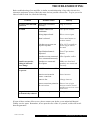
1
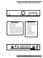
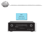
A3
DUAL MONO INTEGRATED AMPLIFIER
INSTRUCTIONS FOR USE
Thank you for purchasing the Musical Fidelity
A3 remote control integrated Amplifier.
Used properly and carefully, it should give you many
years of outstanding musical reproduction.
The A3 operates in Class A/B which in our experience
offers the ultimate in musical accuracy and pleasure.
The A3 is based on ideas and principles developed
in the legendary X-A1 Integrated amplifier
but with subtle changes and improvements.
Aesthetically, the A3 is a perfect match for the
A3 CD player and the A3 Tuner.
Together, they form one of the finest hi-fi systems
that you can own today.
Dust regularly with a soft duster or soft brush but be
careful when using cleaning or polishing agents - they may
harm the surface finish.
If you have any questions about anything in your
audio system, please consult your dealer who is there to
help and advise you.
issue 3/13.07.2000
A3
Instructions for Use. Page 1 of 9
SAFETY INFORMATION
IMPORTANT!
This unit is supplied in the UK with a mains lead fitted with a moulded 13 amp plug.
If, for any reason, you need to cut off this plug, please observe the following safety precautions.
Please dispose of the cut-off plug safely. It must not be plugged into a mains power supply.
The wires in the mains lead supplied with this appliance are coloured in accordance
with the following code:
Green and yellow..............Earth
Blue...............................Neutral
Brown................................Live
WARNING - This appliance must be earthed
As the colours of the wires of the mains lead of this appliance may not correspond with the
coloured markings identifying the terminals in your plug, proceed as follows:
The wire which is coloured green-and-yellow must be connected to the terminal in the plug
which is marked with the letter E or coloured green or green-and-yellow, or by the earth
symbol.
The wire which is coloured brown must be connected to the terminal which is marked with the
letter L or coloured red.
The wire which is coloured blue must be connected to the terminal which is marked with the
letter N or coloured black.
If connecting to a BS1363 plug, a 10 amp fuse must be used.
WARNING - Radio Frequency Interference (RFI)
This hi-fi product has been tested to ensure that its operation will not be adversely affected by
normal background levels of RFI. It is possible that if this product is subjected to abnormally
high levels of RFI the unit may be susceptible and not perform as expected. In the unlikely
event of this happening on a regular basis, please contact Musical Fidelity's service department.
The unit has also been tested to ensure that it does not radiate excessive levels of RFI that could
affect other pieces of electronic or electrical equipment.
The electronics in modern hi-fi equipment is complex and hence may be damaged by lightning.
It is possible that during electrical storms the operation of some equipment may be adversely
affected. For complete protection of your hi-fi system during such storms, mains plugs and aerial leads should be disconnected.
Always ensure that when disconnecting and reconnecting your hi-fi equipment the mains
supply is switched off.
issue 3/13.07.2000
A3
Instructions for Use. Page 2 of 9
GENERAL ADVICE
INSTALLATION PRECAUTIONS and USER INFORMATION
Your new A3 is designed and built to provide trouble-free performance but as with all electronic
devices it is necessary to observe a few precautions.
Heed all warnings on the back of the unit.
Only connect the A3 to a mains outlet of the voltage marked on the back of the unit.
A3 will operate in accordance with its specifications as long as the environmental conditions are kept in the following ranges:Temperature 5 to 45 degrees Celsius
Humidity
10 to 90% non condensing
Position the mains lead, speaker leads and signal interconnects where they are not likely
to walked on or trapped by items placed on them.
Do not use near water. The unit shall not be exposed to dripping or splashing and no
objects filled with liquids, such as vases, shall be placed on the unit.
Do not place the unit near direct heat sources such as radiators or other equipment that
produces heat.
Do not place the unit where it can be subjected to direct sun-light.
Do not remove any covers or try to gain access to the inside. The warranty is invalid if
the unit has been tampered with. There are no user adjustments within. Refer all service
work to an authorised Musical Fidelity agent.
Dust regularly with a soft duster or soft brush but be careful when using cleaning or
polishing agents - they may harm the surface finish.
There are fuses in the A3. In the unlikely event that one blows, take your unit to your
audio dealer. Do NOT try to replace the fuse yourself or you will invalidate the warranty.
No naked flame sources, such as lighted candles, should be placed on the unit.
ATTENTION:- This amplifier can run at high temperatures. Under no circumstances
place anything over the unit, such as newspapers or clothing. Under no circumstances
place anything under the unit between the feet. Position in a well ventilated area.
Keep out of reach of children.
For battery disposal, refer to the manufacturers instructions.
Important! Unauthorised opening of the equipment will invalidate any warranty claims.
Note: To help your dealer identify your amplifier if after-sales service is required, please quote
the serial number located on the rear panel of the unit.
issue 3/13.07.2000
A3
Instructions for Use. Page 3 of 9
CONNECTIONS AND FACILITIES
MUSICAL FIDELITY A3 DUAL MONO INTEGRATED AMPLIFIER
PHONO
CD
TUNER
AUX
SACD
TAPE
MONITOR
POWER
IRR
1
2
3
5
12
13
14
15
16
17
18
19
20
21
22
23
24
Power on indicator LED
Power on/off switch
Volume control
Infra red receiver
Phono input select button and LED
CD input select button and LED
Tuner input select button and LED
AUX input select button and LED
SACD input select button and LED
TAPE input select button and LED
Tape monitor button and LED
12
13
14
RIGHT SPEAKER OUTPUT
-
MM
CAUTION
MOUNT UNIT ON SOLID SURFACE. DO NOT REMOVE SCREWS OR
COVERS UNDER ANY CIRCUMSTANCES. NO USER SERVICEABLE
COMPONENTS INSIDE. REFER SERVICING TO QUALIFIED ENGINEER.
SEE OWNERS MANUAL FOR FURTHER INFORMATION.
issue 3/13.07.2000
15
P
H
O
N
O
+
6
7
8
9
11
10
A3 back panel layout
A3 front panel layout
1
2
3
4
5
6
7
8
9
10
11
4
16
C
D
T
U
N
E
R
RIGHT speaker output
Phono earth connection
MM/MC selection switch
Phono input
CD input
Tuner input
AUX input
SACD input
TAPE input
TAPE RECORD output
PREAMP output
LEFT speaker output
IEC mains inlet
17 18 19 20 21 22
A
U
X
S
A
C
D
T
A
P
E
T
A
P
E
R
E
C
P
R
E
O
U
T
23
24
LEFT SPEAKER OUTPUT
-
+
MC
MUSICAL FIDELITY
A3 DUAL MONO INTEGRATED AMPLIFIER
MANUFACTURED IN ENGLAND BY MUSICAL FIDELITY
A3
THIS APPLIANCE
MUST BE
EARTHED
50/60Hz
P
O
W
E
R
C
O
N
S
U
M
P
T
O
IN
4
0
0
W
IMPORTANT
Instructions for Use. Page 4 of 9
CONNECTIONS
CONNECTIONS
Before switching on the stereo system
please read carefully the instructions on
the following pages. The functional
arrangement of the controls makes the
stereo system fairly easy to operate. You
should nevertheless study these instructions to get the best from your equipment.
All connections should be made with the
power OFF.
The A3 has 1 phono input which can be
used for either moving magnet (MM) or
moving coil (MC) cartridges.
The A3 also has 5 line level inputs - CD,
Tuner, Aux, SACD, and Tape.
LOUDSPEAKERS
To get a realistic soundstage and full
dynamic range from your A3, use it with
loudspeakers of a reasonable efficiency
and high power handling. We recommend
power handling of at least 150W. An average rating for a loudspeaker these days is
about 88dB. This should mean that for an
input of 1 watt, measured at 1 metre distance, the sound pressure output will be
88dB. This is the minimum efficiency that
we recommend you should use.
All line level inputs are electrically identical and are suitable for use with any source
component with an output voltage in the
hundreds of millivolts (mV). This includes
CD players, Super Audio CD players
(SACD), tuners, tape machines and the
audio outputs of video recorders, televisions, DVD and LaserDisc players etc.
BEFORE YOU SWITCH ON
You should make all connections to the A3
before switching on.
Follow this routine before you listen for
the first time, and each time you change
any connections.
1
Check all the inputs and outputs to
the A3.
2
Then check again.
3
Turn the volume control to
minimum.
4
Now you can switch on the power
and carefully advance the volume to
the level you want and enjoy the
music.
issue 3/13.07.2000
A3
Instructions for Use. Page 5 of 9
OPERATION
PREAMP OUTPUT
REMOTE CONTROL
The A3 has a permanently active preamp
output situated on the back panel. This
provides extra flexibility for use in multiroom or surround-sound systems etc. This
signal comes from the A3's internal preamp and its output level is thus controlled
by the front panel volume control.
The remote control enables you to activate
the main functions of the amplifier from
the comfort of your armchair. Pressing the
volume up or down buttons on the remote
handset will advance the motorised volume
control in the desired direction.
Input selection can also be controlled with
the remote handset.
This output allows easy upgrading by passive bi-amping with a pair of X-A50s or
X-A200s.
The mute button on the remote handset
mutes the output. To show the amplifier is
muted the red LED in the volume control
goes out. Press the mute button again to
switch the mute off, the red led will light
again.
To bi-amp (which requires bi-wireable
speakers) an extra pair of X-ponent amplifiers is attached to this permanent preamp
output.
The A3's built in power amps can then for
instance drive the left and right channel
tweeters whilst the X-A50s or X-A200s
drive the left and right channel bass units.
The following should be noted when operating the amplifier using the remote control. The Infra Red receiver is the small
red lens marked I.R.R. situated on the front
panel. It is important to ensure that when
operating the remote control, the line-ofsight from the remote to the infra red
receiver is not obstructed.
Passive bi-amping in this way can give
noticeable gains in clarity, imaging and
bass weight.
- Point the remote control (transmitter) towards the I.R. lens (infra red)
on the amplifier.
If you would like further details please
contact your dealer or Musical Fidelity
directly.
- Visual contact must exist between
the transmitter and receiver.
- If the range of the remote control
decreases dramatically, replace the
batteries with new ones. (dispose of
old batteries as per the manufacturers
instructions)
issue 3/13.07.2000
A3
Instructions for Use. Page 6 of 9
OPERATION
PHONO
OFF TAPE MONITORING
The A3 has a phono input for turntables
fitted with either a moving magnet cartridge (MM) or a moving coil cartridge
(MC). Use the MM/MC push button
switch to select the type of cartridge that is
fitted to you turntable.
In conjunction with a 3-head cassette deck,
off-tape monitoring allows the user to
compare the recorded to original sound
whilst a recording is made. To do this,
first select the required source in the normal way and start recording. The Tape
Monitor button on the front panel can now
be used to switch between the source signal and the recorded signal allowing direct
comparison.
IMPORTANT NOTE Do not operate
the MM/MC switch with the volume
turned up.
Some turntable/pick-up arm combinations
are fitted with an extra wire called a chassis earth, which should be connected to the
green earth terminal on the back of the
amplifier.
The red LED just above the tape monitor
button indicates that tape monitor is selected.
Note that tape (the recorded signal) is
selected when the LED is lit. On some 3head cassette decks there is an additional
'tape/source' switch which will need to be
in the 'tape' position for the above to work
TAPE RECORDING
The A3 has a single tape circuit with facilities for off-tape monitoring with 3-head
cassette decks.
If you are in any doubt consult your tape
machine's manual.
Connection of your tape machine to the A3
should be as follows. The tape machine's
Tape/Line outputs go to the A3's 'Tape'
input sockets.
The tape machine's Tape/Line inputs go to
the A3's 'Tape Record' output.
To record, simply select the required
source with the source selector button on
the front panel. The selected source will
now be sent to the 'Tape Record' output for
recording by the attached tape machine.
You will also be able to hear the selected
source through the loudspeakers.
Note - you can adjust the listening level
with the volume control without affecting
the recording level.
issue 3/13.07.2000
A3
Instructions for Use. Page 7 of 9
TROUBLESHOOTING
Basic troubleshooting of an amplifier is similar to troubleshooting of any other electrical or
electronic equipment. Always check the most obvious possible causes first. To give you a few
ideas of what to look for, check the following:
Problem
Probable Cause
Remedy
No power when POWER
is pressed
Mains plug not inserted
correctly
Plug in securely
No sound
Volume control is set
to minimum
Turn up the volume
Wrong input selected
Select correct input
Mute is selected
Press mute button on
remote control
Unit has not yet come out
of power-up mute
Wait 10-15 seconds on
power-up for unit to
un-mute
Tape Monitor button is
depressed
Press Tape monitor
button
Speakers are not connected, Check speaker cables
or are connected incorrectly
Sound is not precise,
lacking in bass and
stereo image
Speakers are connected
out of phase
Make sure that both
speakers are connected
correctly
Remote control unit will
not operate
POWER switch set to OFF
Set switch to ON
Batteries not inserted in
remote control unit
Insert batteries
Batteries flat
Change batteries
Remote control not pointed at Ensure line of sight
IR receiver lens
between remote control
and IR receiver lens is not
obstructed
Range of remote control
has dramatically reduced
Batteries running out
Change batteries
If none of these actions effect a cure, please contact your dealer, or an authorised Musical
Fidelity service agent. Remember, never open the case of the A3 yourself, as this will invalidate the guarantee.
issue 3/13.07.2000
A3
Instructions for Use. Page 8 of 9
SPECIFICATIONS
A3
INTEGRATED AMPLIFIER
Power output
85 watts per channel into 8 Ohms
170 watts per channel into 4 Ohms
THD
< 0.008% at 1KHz
Frequency response
20Hz - 20KHz +0.5dB
Inputs
1 phono 5 line level
Outputs
Speaker outputs, Tape out, Preamp out.
Input sensitivity (line inputs)
Input sensitivity (MM input)
Input sensitivity (MC inputs)
300mV
3.5mV
350uV
Input impedance
100KOhm
S/N ratio (line inputs)
> 83dB ‘A’ weighted
> 96dB ‘A’ weighted
> 78dB ‘A’ weighted
> 80dB ‘A’ weighted
> 70dB ‘A’ weighted
> 72dB ‘A’ weighted
S/N ratio (MM)
S/N ratio (MC)
(Ref 1W)
(Ref 85W)
(Ref 1W)
(Ref 85W)
(Ref 1W)
(Ref 85W)
Power consumption
400W Max
Dimensions
Amplifier 440 x 95 x 400mm (W x H x D)
Height includes feet, depth includes terminals
Power requirements
100/115/230V AC 50/60Hz
(Factory preset)
Weight
13 kg (un-boxed)
Musical Fidelity reserves the right to make improvements which may result in specification or feature changes without notice.
issue 3/13.07.2000
A3
Instructions for Use. Page 9 of 9