1
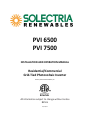
PVI 6500 PVI 7500 INSTALLATION AND OPERATION MANUAL Residential/Commercial Grid‐Tied Photovoltaic Inverter © 2012, Solectria Renewables, LLC All information subject to change without notice REV H 05/07/2012 Installation and Operation Manual (REV H) PVI 6500 / PVI 7500 IMPORTANT REGISTRATION AND WARRANTY INFORMATION For warranty to become active, this inverter must be registered. To activate warranty and register inverter, please visit the link below. www.solren.com/registration IMPORTANT SAFETY INSTRUCTIONS
Before installing or using the PVI 6500‐7500, please read all instructions and caution markings in this manual and on the PVI 6500‐7500 unit as well as the PV modules. All electrical installations shall be performed in accordance with all local and national electrical codes. The PVI 6500‐7500 inverters are listed to UL1741/IEEE1547/CSA 22.2#107.1 (and comply with IEEE 62.41).
The PVI 6500‐7500 inverters contain no user serviceable parts. Do not open the inverter. Please contact Solectria Renewables or a Solectria Renewables authorized system installer for maintenance.
Connection of the PVI 6500‐7500 to the electric utility grid must be done after receiving prior approval from the utility company and performed only by qualified personnel.
Completely cover the surface of all PV‐arrays with opaque material before wiring them or use other methods to prevent shock hazard. PV arrays produce electrical energy when exposed to sunlight and could create a hazardous condition. SAVE THESE INSTRUCTIONS 2 Instaallation and Operation M
Manual (REV H) PVI 6500
0 / PVI 7500
This manual contaains important instructions that shall be followed duriing installation and maintenance of the P
PVI 6500 and PVI 0 Inverter. 7500
To re
educe the riskk of electrical shock, and to
o ensure safe installation and operation of the inverteer, the follow
wing safety sym
mbols are u
used to indicate dangerous conditions an
nd important safety instrucctions. WARNING: This symbol ind
dicates a fact or feature very important ffor the safety of the user to
o prevent inju
ury or death and/orr which can caause serious hardware damage if not followed approp
priately. Use extreme
e caution whe
en performingg this task. mation to prevvent damage tto this producct CAUTION: Prresents inform
OUND SYMBO
OL EARTH GRO
ol indicates a ffeature that iss important eiither for optim
mal or efficien
nt use and opttimal NOTE: This arrow symbo
system opeeration. EXAMPLE: This sun symb
bol indicates aan example. 3 Installation and Operation Manual (REV H) PVI 6500 / PVI 7500 General Safety Precautions
Trained, qualified personnel are required to mount, reconfigure or repair this device. Do not work on the inverter when it is energized. Personnel must remove all conductive jewelry prior to installation or service of the device, parts, connectors, and/or wiring. Use proper lifting techniques whenever handling enclosure, equipment or parts. An equipment‐grounding conductor must be provided for the inverter in accordance with local codes and regulations. A DC grounding connection must be provided for the inverter in accordance with local electrical code. The normally grounded conductor may be ungrounded and energized when a ground fault is indicated. The AC Neutral connection is only for voltage sensing and shall be neither used to carry currents nor bonded to ground inside the inverter except in the case of 277VAC use, where the neutral is current‐
carrying. This list does not contain all measures pertinent to the safe operation of the device. If special problems arise which are not described in sufficient detail for the purposes of the user, contact your distributor, dealer or call the Solectria Renewables customer service hotline. SAVE THESE INSTRUCTIONS Safe Installation and Operation
Installation of the device must be in accordance with the safety regulations and all other relevant national or local regulations. Correct grounding and over current protection must be provided to ensure operational safety. Switch off and lock out the circuit breakers before installation and wiring. Avoid standing in water when working on the inverter. Confirm absence of voltage with an AC voltmeter. PV arrays will be energized when exposed to light. Cover the arrays with opaque material during installation and wiring. Confirm absence of voltage with a DC voltmeter. Attach the circuit panel cover correctly before switching on the circuit breakers. Do not install the inverter in direct sunlight. When no external voltage is present, the inverter can still hold high DC voltages and an electrical shock hazard may still be present. Allow at least 5 minutes for the inverter to discharge completely after disconnecting the AC and DC sources from the inverter. Verify absence of voltage with a DC voltmeter. External heat sinks can reach high enough temperatures in normal operation to cause skin burn injury when these parts are touched. To prevent the risk of fire hazard, do not cover or obstruct the heat sink. Allow changes in your electrical system to be carried out only by qualified electricians. 4 Installation and Operation Manual (REV H) PVI 6500 / PVI 7500 Repair and Maintenance The inverter contains no user serviceable parts. Only Solectria Renewables personnel are authorized to carry out internal repair and maintenance of the unit. Please return the device for repair and maintenance. For maintenance and replacement of the fuses by qualified personnel, please refer to section 5.3. WARNING! Do not make alterations or tamper with components in the inverter without the manufacturer’s authorization unless specified elsewhere in this manual. They may result in injury, electric shock, or fire and void the warranty. Wiring the inverter
Input/Output Terminals: Use 90°C (194°F), #10 AWG to #6 AWG copper wire for DC connections and #10 AWG to #6 AWG copper wire for AC connections. Use only solid or stranded wire but not fine‐stranded wire. Reconfirm that all connections have been performed properly and all screws are properly tightened and torqued. WARNING! All electrical installations and the associated wiring shall be done in accordance with the local and national electrical codes and should follow the important safety instructions in this manual. WARNING! Make sure that you use suitable connecting conductors for both the AC and DC wiring. The conductors must be adequately sized and suitably specified for temperature extremes, UV radiation and other possible hazards. Connection of the AC conductors WARNING! Reconfirm that the circuit breaker to the utility / breaker panel is switched OFF and locked out before connecting the conductors from the breaker to the AC terminal blocks. Connection of the DC conductors !
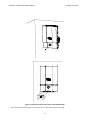
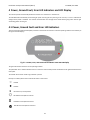
CAUTION! Identify the polarity of DC voltage on each PV string and connect respectively to the input terminals marked “UNGROUNDED CONDUCTOR” and “GROUNDED CONDUCTOR”. Make sure the DC voltage generated by the PV array is equal or less than 600 VDC factoring in open circuit extreme cold temperature. WARNING! Protect the DC conductors to the inverter from all possible hazards that could damage the wires. WARNING! Hazardous voltage is still present on the device after disconnection of all PV DC inputs. Allow 5 minutes for the inverter to discharge the stored energy completely. Verify absence of voltage with a DC voltmeter. WARNING! PV arrays will be energized when exposed to light. Cover the arrays with opaque materials during installation and wiring. 5 Installation and Operation Manual (REV H) PVI 6500 / PVI 7500 Table of Contents 1 Introduction ......................................................................................................................................... 2 Installation ........................................................................................................................................... 2.1 Checking for Shipping Damage ..................................................................................................... 2.2 Inverter Mounting and Placement ................................................................................................ 2.3 Electrical Connection and Connection to Electrical Utility Grid, Surge/Lightning Arrestors and Grounding Electrode Conductors .................................................... 2.4 Connection of AC Wiring .............................................................................................................. 2.5 Connection of DC Wiring .............................................................................................................. 2.6 Connection of Communication Wiring .......................................................................................... 2.4 Communication ID adjustment ..................................................................................................... 3 Commissioning the Inverter and PV System ......................................................................................... 4 Power, Ground Fault, Error LED Indicators and LCD Display ................................................................. 4.1 Power, Ground Fault and Error LED Indicators ............................................................................. 4.2 The LCD Display ............................................................................................................................ 5 Trouble Shooting .................................................................................................................................. 5.1 Diagnosis and analyzing data ........................................................................................................ 5.2 Explanations of Error Messages .................................................................................................... 5.3 Maintenance ................................................................................................................................ 5.4 Factory Service ............................................................................................................................. 5.5 Inverter Replacement ................................................................................................................... 6 Product Warranty & RMA Policy .......................................................................................................... 6.1 Warranty Policy ............................................................................................................................ 6.2 Return Material Authorization Policy............................................................................................ 7 Technical Data...................................................................................................................................... 7.1 Technical Information and specifications...................................................................................... Appendices .......................................................................................................................................... Appendix A: Brochure / Datasheet ...................................................................................................... Appendix B: Example PV String Sizing Tables ....................................................................................... Appendix C: Contact Information & Authorized Dealers and Installers ................................................ Appendix D: Positive Grounding Option .............................................................................................. Appendix E: Fault Repot Form ............................................................................................................. Appendix F: UL1741/IEEE1547 Listing Letter…………………………………………………………………………………….. 6 7 10 10 10 18 24 27 31 33 35 37 37 39 48 48 48 51 53 53 62 62 65 66 66 71 71 71 71 71 74 75 Installation and Operation Manual (REV H) PVI 6500 / PVI 7500 1 Introduction The PVI 6500 and PVI 7500 are single phase, grid‐tied PV inverters designed to be interconnected to the electric utility grid. By following the instructions in this manual, the PVI 6500 ‐ PVI 7500 can be installed and operated safely. This installation guide is to be used as reference for commissioning and as a guideline on how to use the inverter most effectively. Feeding power onto the grid involves conversion of the DC‐voltage from the PV‐array to grid compatible AC‐voltage by “inverting” DC to AC. This unit feeds power into a standard 240 VAC split phase electrical system or two phases of a 208 VAC, 3‐
phase commercial, industrial or institutional facility’s electrical system that is connected to the electric utility grid. The inverter can also be connected to one phase and neutral of a 277 VAC electrical service. If the PV system and inverter are providing the same amount of electrical power that the facility is using, no power is taken from or fed onto the utility grid. If the facility is using more power than the PV system is providing, then the utility grid provides the balance of power. If the facility is using less power than the PV system is generating, the excess is fed into the utility grid. Be sure to look into local regulations regarding net metering and interconnection in your local area. Note that some utilities need to change their revenue kWh meter to a bi‐directional type for proper net metering measurement or incentives/billing. Photovoltaic Array PVI 6500‐7500
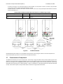
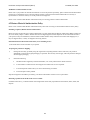
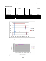
Inverter Fig. 1.1 Grid‐tied inverter application 7 Electric Utility Grid Installation and Operation Manual (REV H) PVI 6500 / PVI 7500 The concept of stringing PV modules The use of a PV string significantly reduces the cabling costs on a photovoltaic system. The use of strings of several PV modules in series and multiple parallel strings of PV modules is delivering a high operating voltage to the solar inverter. This advantage is primarily reflected in a higher efficiency of the inverter and lower wiring cost. Data acquisition, display and communication The integrated data acquisition and communication capability of the PVI 6500‐7500 allows comprehensive tracking of system performance data. All error messages and operating conditions of the PVI 6500‐7500, as well as those on the PV system are shown on the display. An optional full‐featured, inverter direct data acquisition and logging gateway and web‐based service is available from Solectria Renewables, called SolrenView (http://www.solrenview.com). The gateway allows the inverter to deliver information to the Solrenview server through the facility’s internet service. Technical structure of the PVI 6500 and PVI 7500 A high frequency switching bridge circuit operating in conjunction with a high frequency transformer provides galvanic isolation of the photovoltaic system from the building’s AC power and electrical utility grid. The Maximum Power Point tracking algorithm continuously controls the PV voltage and current to produce the maximum possible power output during varying sunlight strengths and PV module. The inverter’s DC input voltage window is designed to cover a PV array voltage range of 230 to 550 VDC. (600VDC maximum open circuit voltage). This allows many modules from different manufacturers to be used. The inverter consumes nearly zero standby power at night. The daytime control circuit power use of the inverter is minimal, resulting in a very high inverter efficiency. The housing and heat sink for the PVI 6500‐7500 is manufactured using a heavy aluminium extrusion with an anti‐corrosion finish. The housing is designed to meet the NEMA3 standard and is resistant to rain and snowfall. The heat sink and fan performance allow operation of the inverter at ambient temperatures of ‐13° F (–25° C) to +131° F (+55° C) for PVI 6500 and ‐13° F (–25° C) to +122° F (+50° C) for PVI 7500 at full rated power. The heat sink conducts away heat generated from energy losses in the power electronics. Internal temperature regulation provides protection against excessively high temperatures inside the PVI 6500‐7500. Should the inverter reach its maximum rated temperature, the power produced is automatically reduced to prevent excessive inverter temperature. The PVI 6500‐7500 will only operate in parallel with the utility grid. AC grid monitoring is performed by microcontrollers configured to meet the requirements of UL1741/IEEE1547/CSA 22.2#107.1, which include disconnection from the grid during abnormal frequency or voltage events. If this happens, the inverter will monitor the grid and reconnect to it 5 minutes after the grid has come back to normal. Disconnection from the grid is important to protect the electrical and utility line workers who may be working to restore the grid and not be aware of the presence a PV generator on that line. Power grid faults that will cause the PVI 6500‐7500 to isolate itself from the power grid:
AC grid voltage The grid voltage must not go outside the range of +10/‐12% of the nominal 240, 208V or 277V AC grid voltage, per IEEE Std 1547, § 4.2.3 (US). The inverter will isolate itself from the grid if these limits are exceeded. The inverter will automatically detect and synchronize to 240, 208 or 277VAC when the neutral is connected to the inverter. If it is desired to connect to 208, 240VAC without a neutral connection, then the selection must be set either at the factory or can be adjusted in the field by a qualified installer. It is not possible to operate at 277VAC without a neutral connection because the neutral is part of the current‐carrying circuit.
AC grid frequency The power grid frequency must not go outside of the range of +0.5Hz and ‐0.7Hz of the nominal 60Hz grid frequency, per IEEE Std 1547, § 4.2.4 (US). The inverter will isolate itself from the power grid if these permitted limits are exceeded. 8 Installation and Operation Manual (REV H) PVI 6500 / PVI 7500 Another important safety feature that has the ability to isolate the inverter from the grid is the DC ground fault detection and interrupt (GFDI) circuit. The PV array’s grounded conductor is bonded to ground inside the inverter through the GFDI fuse (and must not be bonded to ground at any other point outside of the inverter). PVI 6500‐7500 Description 7
11
5
9
8
10
3
2(inside)
1
4
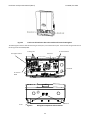
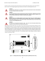
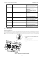
6
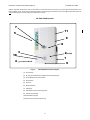
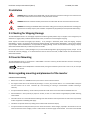
Fig. 1.2 PVI 6500/7500 Features Diagram (1) AC knockouts (2) PV array ground fault interrupt (GFDI) fuse (inside wiring box) (3) Combined DC/AC disconnect switch (4) DC knockouts (5) Heat sink (6) RS‐485 interfaces (7) LCD display (8) LED indicators of basic operating status (9) Inverter Serial Number (10) Detachable wiring box (11) Quick‐mount wall plate (behind unit) 9 Installation and Operation Manual (REV H) PVI 6500 / PVI 7500 2 Installation WARNING: Before installing the PVI 6500‐7500, read all instructions and caution markings in this manual and on the PVI 6500‐7500 as well as those written on the photovoltaic modules. WARNING: Electrical installation shall be performed in accordance with all local and national electrical codes. WARNING: Connecting the PVI 6500‐7500 to the electric utility grid must only be performed after receiving prior approval from the utility company and installation completed only by qualified personnel/licensed electrician(s). 2.1 Checking for Shipping Damage The PVI 6500/7500 inverters are thoroughly inspected and tested rigorously before they are shipped. Even though they are delivered in a rugged, heavy cardboard box with foam inserts, the inverters can be damaged in shipping. Please inspect the inverter thoroughly upon delivery. If any damage is discovered please notify the shipping company immediately. If there is any question about potential shipping damage, contact Solectria Renewables. A photo of the damage may be helpful. Solectria Renewables is not responsible for shipping damage. A claim must be filed with the shipping company. Solectria Renewables will assist you with this process as needed. Do not accept the unit if it is visibly damaged or if you note visible damage when signing shipping company receipt. Do not remove the unit from packaging. If it is determined that the unit must be returned, an RMA number must be obtained from Solectria Renewables. 2.2 Inverter Mounting The PVI 6500/7500 inverter is comprised of a sealed NEMA 3 corrosion resistant, painted aluminum enclosure containing all electrical and electronic components. NOTE: If the PVI 6500/7500 is mounted outside, during the installation process and in case of rain, do not open the inverter. Notes regarding mounting and placement of the inverter Criteria for inverter mounting:
Because the inverter is in a NEMA3 enclosure, the inverter can be mounted outdoors.
The longest inverter life can be achieved by mounting it in a clean, dry and cool location. It is recommended to keep the unit out of direct rain or snow. Protection by a roof overhang or covering is recommended if outdoor mounting is necessary.
For optimal electrical efficiency, use the shortest possible AC and DC wires and use the maximum allowable wire size.
Avoid installation in close proximity to people or animals, as there is a small amount of high‐frequency audible switching noise emitted.
Install the inverter in an accessible location following local codes. Note that code requirements for clearances and proximity to other equipment and building walls apply.
Installation at eye level allows easy reading of the indicator LEDs and the LCD display.
For optimal inverter life and performance, do not mount the inverter in direct sunlight, especially in hot climates. If the unit must be mounted in direct sunlight, a silver or white metal sun‐shield is highly recommended. It is further recommended 10 Installation and Operation Manual (REV H) PVI 6500 / PVI 7500 that the inverter be mounted on the north or east side of buildings or on the northern side of a ground mounted PV array. Following these guidelines help prevent the unit from limiting the power produced due to an excessively high inverter temperature.
In hot climates, the housing and heat sink can reach 160o F (70o C) and must be mounted on an appropriate material for this temperature as well as one that meets local codes. The inverter should not be mounted where people are likely to touch the case or heat sink due to the high potential temperature. CAUTION: Please follow these guidelines:
The inverter weighs approximately 89 lbs (40.8kg) (shipping weight in the box with mounting plate is approximately 104 lb). Be sure to use a mounting method that will safely hold this weight.
The ambient temperature for the PVI 6500 must be between –13o F (–25o C) and +131o F (+55o C) for continuous, full power operation. For the PVI 7500 the maximum allowable ambient temperature is +122o F (+50o C). The inverter will automatically reduce power or shut down to protect itself if the ambient air temperature rises above 131o F (55o C)/ 122o F (50o C). Relative humidity shall be within 0% and 95%.
Local and national electrical codes require that the inverter be connected to a dedicated AC circuit. The code also imposes limitations on the size of the inverter and the manner in with it is connected to the utility grid. See local codes for more information.
The cooling air enters at the bottom of the heat sink and exhausts at the top of the unit. See Figure 2.1.1 for recommended clearances for cooling air and space around the inverter.
If you are installing the inverter in a utility vault or electrical closet, the air circulation must be sufficient for heat dissipation o
o
o
o – provide external ventilation, to maintain an ambient condition of less than 131 F (55 C)/ 122 F (50 C) for the PVI 6500 and PVI 7500. The ambient temperature should be kept as low as possible.
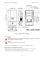
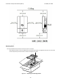
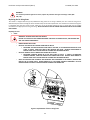
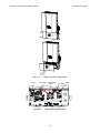
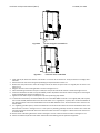
Use the dimensional diagrams in Fig. 2.2.1 and 2.2.2, for correct mounting of the inverter. 11 Installation and Operation Manual (REV H) PVI 6500 / PVI 7500 Fig. 2.2.1 PVI 6500/7500 Dimensional Diagram Placement and location WARNING! Some parts of the heat sink can reach temperatures over 160F (70℃). Keep flammable, explosive materials or trash at an appropriate distance from the inverter! WARNING! Do not expose the inverter to corrosive liquids and/or gasses. ∙ The mounting bracket should be fastened to a concrete or a masonry wall using appropriate anchors. Conduit Locations, Pre‐punched Holes and Knock‐outs ∙ Multiple concentric Knock‐outs (KOs) are on the bottom, back and side of the AC and DC ends of the wiring box. ∙ Large Knock Outs are for 1”‐ ½” conduit. Small Knockouts are for ¾”‐½” conduit. ∙ Concentric KOs are on the back of the AC and DC sides of the wiring box for a “hidden wiring” installation. 12 Installation and Operation Manual (REV H) Fig 2.2.2 PVI 6500 / PVI 7500 Clearances recommended for PVI 6500/7500 inverter installation Mounting details The steps listed below describe how to mount the inverter on the wall: ‐ After taking the inverter out of the cardboard box, you will find the bracket in the bag behind the heat sink. The bracket needs to be picked up from the inverter as shown in the figure 2.2.3 below. Fig 2.2.3 Unpacking the mounting bracket 13 Installation and Operation Manual (REV H) Fig 2.2.4 PVI 6500 / PVI 7500 Remove the bracket from the inverter Use the bracket (Fig 2.2.5) as a template to mark the hole locations on the wall. After drilling the holes, the mounting bracket should be fastened to the wall with screws or screw‐anchors as shown in Figure 2.2.6. m
2.91”
4m
190mm
120mm
70mm
4
525mm
1.
4.75”
20.67” 7.5”
405m
16.94” m
14 70mm
2.75”
2.75
9.88”
98.43
250mm
7.12”
180mm
125mm
4.94”
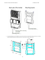
Installation and Operation Manual (REV H) Fig 2.2.5 Mounting bracket and its dimensions PVI 6500 / PVI 7500 30cm
11.8”
60cm
23.6”
3 0 cm
11.8”
58”‐
67”
100~170cm
¼” diameter mounting screw recommended or 3/16‐1/4” anchor bolt
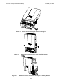
Fig 2.2.6. Fastening the mounting bracket 2. Once the mounting bracket is fastened to the wall, the inverter and the wiring box can be hooked onto the bracket and slipped down into place. Make sure the lower lip on the bracket hooks into the window on the back of the inverter as shown in Fig. 2.2.7. 15 Instaallation and Operation M
Manual (REV H) PVI 6500
0 / PVI 7500
Flange with
F
m
mounting
holees
F
Fig 2.2.7 M
Mounting Inv
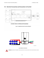
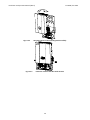
verter on brracket 16 Installation and Operation Manual (REV H) PVI 6500 / PVI 7500 Fig 2.2.8 Fasten the inverter with screws at the bottom flange After the inverter is hooked properly on the bracket, secure it with screws at the bottom flange. 17 Installation and Operation Manual (REV H) PVI 6500 / PVI 7500 2.3 Electrical Connection and Connection to the Grid * Equipment grounds, grounding electrode conductor
and ground fault detector/interrupter not shown
PVI 6500‐7500 PV SYSTEM BLOCK DIAGRAM
Fig. 2.3.1 Simplified electrical connection diagram * Colors used in wiring diagram are to differentiate conductors and are not representative of wire colors used pre code.
Fig 2.3.2 Basic Connections
WARNING: All electrical installations shall be performed in accordance with local and national electrical codes. 18 Installation and Operation Manual (REV H) PVI 6500 / PVI 7500 The grounded DC photovoltaic connection is bonded to ground within the inverter through the ground fault detection and interrupt circuit (GFDI) and should not be bonded at any other point in the system. The ungrounded DC connection must never be grounded at any time. AC and DC (PV) Connections: The PVI 6500‐7500 inverters are equipped with covered holes and KOs for conduit fittings that are code‐compliant for use with several sizes of rigid and flexible metallic or non‐metallic conduit. All conduit and wiring installation is done in the wiring box. This design allows installation and wiring of the inverter to be done without opening the main inverter enclosure which must never be opened. AC & DC terminals allow for #10 to #6 AWG copper conductors. Lightning and Surge Protection: The inverter is designed with certain protections against voltage surges with certification to UL1741/IEEE1547 and CSA22.2#107.1 (including ANSI/IEEE 62.41/62.42). In areas of frequent lightning storms or when no primary lightning protection system is used (air terminals), additional surge protection on DC and AC side and solid grounding provisions are important for best protection against utility voltage transients and surges created by indirect lightning strikes. The installation of a lightning arrester or other UL listed surge arrester of the correct specification is recommended on both the DC and AC sides of inverter. They can be installed on the outside of the wiring box or other locations in the system and wired using the manufacturer's directions. When coordinated with the Surge Protection Device, lightning arrestors give important added protection from direct lightning strikes and resulting surges. Make sure to check the lightning protection system of the building and perform any necessary upgrade before the PV system is installed. A solid lightning protection scheme is especially important for areas prone to thunderstorms and possible nearby lightning strikes. Although these added precautions will not guarantee that there will be no damage from lightning, they can help prevent or limit potential damage. Grounding Electrode Conductor: As with all PV systems, a Grounding Electrode Conductor must be installed per code. This conductor should be sized according to these code requirements. This conductor should be terminated on the labeled ground point located at the bottom of the wiring box where the DC and AC equipment ground conductors also are terminated. AC Voltage: The PVI 6500‐7500 inverters are 240V AC grid connected devices. They are also suitable for 208V and 277V AC grid‐connected use. For example, connection between two phases of a 208V AC, 3‐phase service or connection between one phase and neutral of a 277V AC service (where acceptable by code). No unit (PVI 6500 or 7500) can be used with a 120V AC service. The units are factory pre‐set to auto‐detect 277VAC, 240VAC or 208VAC when connected with a neutral. They can also be configured for either 240 or 208 VAC without a neutral at the factory or by a qualified installer. Use with 277VAC must always use a neutral as the neutral is used as a current carrying conductor. WARNING: The inverter should not be opened at any time unless authorized by Solectria. The unit is sealed at the factory and its UL listing will no longer be valid and the warranty will be void if opened or tampered with in any way. Multiple Units: Multiple PVI 6500‐7500 units can be used at the same location as long as all electrical codes, local building codes and area utility guidelines are followed. If multiple units are used, each inverter must have its own dedicated AC over current protection device, and PV strings cannot be wired to multiple inverters. 19 Installation and Operation Manual (REV H) PVI 6500 / PVI 7500 AC Over Current Protection Device: A dedicated AC over current protection device is required for each PV inverter. Every PVI requires a 208V, 240V or 277V AC rated 2–pole over current protection device. The following is a table showing the appropriate over current protection device rating for the PVI 6500 and 7500 at different service voltages. AC Voltage
PVI 6500
PVI 7500
208VAC
40A
50A
240VAC
35A
40A
277VAC
30A
35A
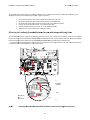
AC and DC Disconnects: The integral AC & DC disconnects are standard features of the PVI 6500‐7500 inverters. The PV system may need additional AC or DC disconnect if required by the utility or local code. Connecting the AC Inverter Wiring: WARNING: The wiring of the PV inverter’s AC and DC connections must only be done with the building AC circuit breaker off and locked out and the PV array disconnected or covered with an opaque material (or other method that establishes electrically safe working conditions). Both AC and DC should be disconnected or turned off. The PVI 6500‐7500 inverters are not capable of feeding currents back into the PV array from the AC source including into short circuit(s) or fault(s) in the PV array or string(s). Connecting the Inverter Wiring: WARNING: Follow PV module manufacturer’s installation directions. PV arrays produce electrical energy when exposed to light and could create a hazardous condition. Disconnect array conductors when wiring the inverter or cover the array with an opaque material prior to wiring. WARNING: Before connecting the connectors of the PV module to the DC inverter terminals, check the correct polarity and admissible PV module voltage between the (+) and the (‐) wire connectors of the PV module. The PV module open circuit voltage must be below 600V DC (Vpv < 600V DC) under all temperature conditions per code. WARNING: Even when in the off position, the fused PV combiner and the DC disconnect terminals will remain live on the PV side when the PV modules are in daylight. Wiring the inverter The cover of the wiring box needs to be removed before wiring the inverter. First the DC/AC disconnect switch shall be turned to the OFF position as shown in the Figure 2.3.3. Remove the 4 screws, and then the cover of the wiring box shown in the figure 2.3.3 and 2.3.4. 20 Installation and Operation Manual (REV H) Fig 2.3.3 PVI 6500 / PVI 7500 Turn the DC/AC disconnect switch OFF Fig 2.3.4 Remove the 4 screws on the wiring box and remove the cover `
After the wiring box cover is removed, the conduit hole covers can be removed (or KOs in other locations punched out) as shown in the figure 2.3.5 for the DC and AC conduits which will enter and exit these locations. 21 Installation and Operation Manual (REV H) Fig 2.3.5 PVI 6500 / PVI 7500 Punch out the knockouts where the conduits will enter the wiring box. The following three sections describe the wiring for the AC, DC, and communication ports. The AC and DC wiring shall be done in the wiring box of the PVI 6500/7500. AC Terminal Blocks
PV String Fuse
GFDI Fuse
Fuse Bypass terminal
Ground Bar
DC Terminal
Blocks
RJ45-L
RJ45-R
Fig 2.3.6 Wiring box components and connections 22 Installation and Operation Manual (REV H) PVI 6500 / PVI 7500 Two RJ‐45 connectors are used for external communication to a Solectria communication gateway. The AC terminal block is used to connect to the building/utility grid through a dedicated circuit breaker in the building distribution panel. WARNING! All electrical work shall be done in accordance with the local and national electrical codes and should follow the important safety instructions in this manual. WARNING! Local and national electrical codes state that the inverter must be connected to a dedicated circuit, and that no other outlets or devices can be connected to the same circuit. The code also imposes limitations on the size of the inverter and the manner in which it is connected to the utility gird. WARNING! Make sure that you use suitable conductors for both the AC and DC wiring. The conductors must be adequately sized and of correct temperature rating and sunlight resistant if needed. Use only #10 AWG to #6 AWG, 90C (194F) stranded or solid copper wire (but not fine‐stranded wire) for all AC and DC wiring connections to the PVI 6500/7500 inverter. WARNING! PV arrays will be energized when exposed to light. Cover the arrays with opaque materials during installation and wiring, and/or keep module leads disconnected. Before wiring the PVI 6500‐7500 inverter, the installer needs to determine the grid connection/utility configuration that the inverter will be connected to. The inverter is default set for utility interconnection with a neutral connection. However, it may be reconfigured for a connection without a neutral. The utility voltage configuration jumpers, J210, are located on the control board as shown in figure 2.3.7 are used to set the inverter to be connected to the commonly used utility configuration types shown in the figure 2.3.8. As shown in the figure 2.3.7, the P1 and P2 pins are used to configure the inverter for the connection types of 208V, 240V and 277VAC outputs with or without neutral (with neutral only for 277V). When the inverter is set for the connection configurations with neutral, it can automatically detect the utility voltage and adjust the output AC voltage according the grid voltage. J210 P1
P2
P3
P1
P2
P3
P1
P2
277V / 240V / 208V
With Neutral (Default)
240 V Without Neutral
P3
FAN Auto (Default)
FAN On
208V Without Neutral
Fig 2.3.7 Building/Utility voltage configuration jumpers (qualified personnel only) 23 Installation and Operation Manual (REV H) 12
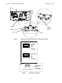
0
12
PVI 6500 / PVI 7500 With Neutral
With Neutral
120 WYE
240/120 Split Phase
120
0
120
Neutral
Neutral
208
P1
P2
240
277V / 240V / 208V
With Neutral
240
120 Stinger
0
24
24
0
27
480
With Neutral
240 Delta
0
120
48
120
277
Neutral
27
7
With Neutral
277 WYE
7
480
240
208
P1
P1
P2
8
20
24
8
0
Without Neutral
20
24
0
P2
240 Delta
Without Neutral
208 Delta
Fig 2.3.8 Utility configurations 2.4 Connection of the AC wiring Use one of the following procedures below to wire the AC conductors. Open the circuit breaker box, switch off and lock out the circuit breaker box that will be used to connect the inverter to the building. WARNING! Reconfirm that the circuit breaker to the grid/utility is switched OFF and locked out before connecting the power wires from the breaker to the inverter AC terminal block. Measure the absence of voltage with an AC voltmeter. !
WARNING! Long wires cause voltage drop. The acceptable range for AC voltage drop is 1.5% of nominal. The voltage drop in excess of 1.5% of nominal AC voltage is an indication that larger size wire should be used. 24 Instaallation and Operation M
Manual (REV H) PVI 6500
0 / PVI 7500
RNING! WAR
Each
h connection to a PVI 650
00‐7500 inve
erter must be
e installed with w
a dedicatted circuit brreaker with 30‐50 3
amp
peres (depend
ding on inverrter model, se
ee “AC Circuiit Breaker” taable) maximu
um branch circuit over cu
urrent prottection. Use #10 AW
WG to #6 AWG
G, 90C (194
4F) copper w
wire for all AC
C wiring connections to tthe PVI 6500
0/7500 inverters. 2.4.1 Conn
nection fo
or AC 208//240V Service/Utilitty Voltage
e (Defaultt) ACIN_N1
DCIN-
DCIN+
J113
J119
Connect the AC
A black wire to th
he
terminal labele
ed "BLACK FOR
208V 240V" off the disconnect
switch.
N wire connected
c
to N te
erminal
L2 wire connected to LIN
NE 2 terminal
L1 wire connected to LIN
NE 1 terminal
Equ
uipment ground wire
w connected
to ground bar
Fig 2.4.1.1
AC Termin
nal Block for AC wire co
onnections with 208/2
240VAC Connect the AC equipm
ment GND wire to the screw on the grou
und bar labele
ed with stamp
p. Connect the white N w
wire to the terrminal labeled
d N on the AC terminal blocck. Connect the L1 wire to
o the terminall labeled Line1
1 on the AC teerminal block.. Connect the L2 wire to
o the terminall labeled Line2
2 on the AC teerminal block.. Tighten tthe screws witth a torque off 15.6 in‐lb (1..7Nm) Reconfirm
m that all connections are ccorrect as desscribed above and all screw
ws are properlyy tightened.
25 Instaallation and Operation M
Manual (REV H) PVI 6500
0 / PVI 7500
2.4.2 Conne
ection for AC 277V SService/U
Utility Volttage ACIN_N1
DCIN-
DCIIN+
J113
J119
J506
Connect the AC
A black wire to the
terminal labeled "BLACK FOR
R
6.
277V" of J506
c
to N
N wire connected
L1 wire
e connected to LINE 1 terminal
Equipm
ment ground wire connected to
ground bar
Fig 2
2.4.2.1
AC Term
minal Block for AC wire
e connectio
ons with 277
7VAC Connect the AC equipm
ment GND wire to the screw on the grou
und bar labele
ed with stamp
p Connect the black AC iinverter wire to the terminal labeled “BLLACK FOR 277
7V” on J506 teerminal block Connect the L1 wire to
o the terminall labeled Line1
1 on the AC teerminal block.. Connect the neutral w
wire to the term
minal labeled N on the AC tterminal blockk. Tighten tthe screws witth a torque off 15.6 in‐lb (1..7Nm) Reconfirm
m that all connections are ccorrect as desscribed above and all screw
ws are properlyy tightened.
26 Instaallation and Operation M
Manual (REV H) PVI 6500
0 / PVI 7500
2.5
5 Conneection o
of the D
DC wiringg !
CAUTION! ergized when exposed to ligght. Use safe working pracctices when w
working on PV
V arrays. PV aarrays are ene
!
WAR
RNING! EXTR
REME SHOCK A
AND FIRE HAZZARD! REM
MOVE ALL PV STRING FUSEES BEFORE WIRING DC CONNECTIONS! DO NOT REIINSTALL FUSEES UNTIL YOU
U ARE READY TO CO
OMMISSION TTHE INVERTER
R (SEE COMM
MISSIONING SEECTION AND PROCDURE). WAR
RNING! DO N
NOT USE PV SSTRING FUSESS LARGER THA
AN 20A! The P
PV strings must have a nam
me plate shorrt circuit curre
ent of less than 9.6A. CAUTION! e no DC backffeed current. However, all other extern
nal source cirrcuits PVI 6500‐7500 inverters are liisted to have
ould be taken into account by system installers when
n determiningg the proper rrating and array wiring aampacity sho
of PV
V string fusess, or a fire hazzard may be p
present if therre is short circcuit in a PV string. RNING! WAR
Veriffy the polaritty and the open circuit voltage from the t PV stringgs before you
u connect thee DC wires to
o the inverter. Applyingg an open circcuit DC input voltage that exceeds the maximum DC
C input voltagge range will ccause irrevversible damaage to the in
nverters and void the warranty! Alw
ways configure
e the DC inp
put voltage range r
correectly before cconnecting the DC input wiires from the PV array to the inverter.
Before any DC w
wiring is attem
mpted within tthe wiring boxx, REMOVE ALLL PV STRING FUSES. 500/7500 inveerter is design
ned with a paair of the DC terminal bloccks which support up to fivve (5) The wiring box of the PVI 65
ind
dependent PV
V strings to be
e fused and co
onnected in parallel and th
hen fed into th
he inverter. TThe PVI 6500‐‐7500 inverterrs are shiipped with fivve 15A, 600V
Vdc rated PV string fuses in the wiring box. Howevver, the size of the PV strring fuses shaall be determined by tthe electrical ratings of thee PV module aand by code reequirements. IN NO CASE SHALL FUSES OF LARGER TTHAN 20A BE USED IN
N THE PV STR
RING FUSE HO
OLDERS. Pleasse refer to Seection 5.3 for the replacem
ment of the PV
V string fuses.. The inttegrated fused
d combiner is able to be bypassed using the provided bypass termin
nals. There are two (2) terminals, labeled “Ungrounded Conductor” and ““Grounded Co
onductor”, loccated in the w
wiring box useed for e DC connections as shown
n in Figure 2.5.1.1. The DC
C equipment gground wire sshall be conneected to a scrrew on the grround the
bar labeled (1.7Nm). PVI 6500/7500 inverter. All the screws sshall be tighteened with a to
orque of 15.6
6 in‐lb in the wiringg box of the P
2.5.1 Conne
ection of the DC wirres for Ne
egatively G
Grounded Arrays Th
he inverter is sshipped a witth negatively ggrounded settting (factory d
default). The p
positive polarity of the DC input voltage from the P
PV string shall be connecte
ed to the term
minal labeled UNGROUNDEED CONDUCTO
OR and the neegative polariity of the DC input voltaage from the PV string shaall be connectted to the terrminal labeled
d GROUNDED CONDUCTOR
R as shown in
n the figure 2..5.1.1 below. Th
he negatively grounded setting is when tthe black DC w
wire is conneccted to the terrminal labeled
d “C” of J505. The red DC w
wire is conn
nected to the terminal labeled “D” of dissconnect switcch. 27 Instaallation and Operation M
Manual (REV H) PVI 6500
0 / PVI 7500
ACIN_N1
DCIN-
D
DCIN+
J113
J119
Red DC wire
Terminal labelled “D”
T
o disconnect switch
of
Black DC wire
Connect to PV+
Connect to PV-
J5
505
Termiinal labeled “C
C”
of J50
05
Fig 2..5.1.1 DC Te
erminal blockks and connecctions using sstring fuses fo
or negatively grounded syystems
The posittive (+) wire o
of the DC inpu
ut shall be con
nnected to thee terminal blo
ock labeled “U
Ungrounded Conductor” and the negative (‐) wire of the DC input sh
hall be conneccted to the terminal labeled
d “Grounded Conductor”, eexcept when using modules. In that case, see A
Appendix D at the end of this manual for further instru
uction. positivelyy grounded m
Wire nutts shall not bee used to join any wires together or to make any con
nnections anyywhere in the PV system exxcept where accceptable by ccode. Wire nu
uts are a frequ
uent cause of f unreliable co
onnections, re
esistive connecctions, and grround faults and
d are not allow
wed in certain
n applicationss by code. Connect the equipmen
nt ground wire to the screw
w of the groun
nd bar labeled
d. Tighten tthe screws to a torque of 15
5.6 in‐lb (1.7N
Nm). 2.5.2 Connection of the DC wires for Negattively Gro
ounded Arrrays with
hout Intern
nal DC Fusess W
When external DC string fusees are used, tthe PVI 6500/7500 inverterr provides a byypass of the internal stringg fuses. In thiss case the positive polarrity of the DC
C input voltagge from the PV string shaall be connectted to the terminal labeleed “UNGROUN
NDED 28 Instaallation and Operation M
Manual (REV H) PVI 6500
0 / PVI 7500
CONDUCTOR (WITTHOUT STRIN
NG FUSES)” off J504 and the
e negative po
olarity of the DC input voltage from thee PV string shaall be nected to the terminal labeled “GROUND
DED CONDUCTTOR” as show
wn in the figuree 2.5.2.1. conn
Th
he negatively grounded settting is that tthe black DC w
wire is conneected to the terminal labeled “C” of J50
05, and the reed DC wire is connected to the termin
nal labeled “D
D” of disconnect switch. ACIN_N1
DCIN-
DCIN+
J113
J119
Red
d DC wire
Terminal
T
labele
ed “D”
of
o disconnect switch
s
J504
Black DC wire
w
Connect tto PV+ J505
Co
onnect to PV‐ Figg 2.5.2.1 Terminal labe
eled “C”
of J505
DC Termin
nal blocks and
d connectionss without striing fuses (usin
ng “J504” byp
pass terminal) for negativvely gro
ounded systeems !
CAUTION! n though the internal DC ffuses are not used, hazard
dous voltage iis still presentt on the fuse holders. The
e fuse Even
pulleer must be ke
ept in the fuse
e holder with the (unused) fuse to reducce the risk of electrical sho
ock. WAR
RNING! Prottect the DC wires w
to the PVI P 6500‐750
00 inverters from any possible hazardss that could damage d
the wires w
h as sharp corrners, edges, or near coverrs where wire
es could be pinched or crusshed). (such
WAR
RNING! Hazardous voltage
e is still prese
ent on the inve
erter after dissconnection o
of all PV DC in
nputs. Allow 5
5 minutes he inverter to
o discharge the DC voltage completely.
for th
29 Installation and Operation Manual (REV H) PVI 6500 / PVI 7500 Fig 2.5.2.2 PV‐ String connections and AC connections 2.5.3 Wiring inverters in parallel PVI 6500‐7500 inverters can be connected in parallel when more power is needed. In the parallel configuration, each inverter shall connect to its own PV array. Do not connect one PV array to more than one inverter. This may cause the inverter to work abnormally. The Figure 2.5.3.1 on the following page shows the connections between inverters and PV arrays in parallel configuration. It is recommended balancing practice to alternate phase connections when connecting more than two inverters to the same three phase service. 30 Installation and Operation Manual (REV H) PVI 6500 / PVI 7500 Correct Configuration from DC Side Incorrect Configuration from DC Side Fig 2.5.3.1 Parallel configuration of inverters is done on the AC side not the DC side. 2.6 Connection of Communication wiring The PVI 6500‐7500 inverter supports two common data interface standards, RS‐232 and RS‐485 that will be used to communicate to a Solectria communication gateway. Only one of the communication interfaces can work at a time. As shown in the Figure 2.6.1, there are two RJ‐45 connectors, RJ45‐R and RJ45‐L that are located on the bottom of the wiring box. The pin numbers of the RJ‐45 connectors and the corresponding signals are described in the Figure 2.6.2 below. If the RS485 is used as the external communication interface and the inverter is the last device in the RS485 loop, then the termination switch shall be put to the ON position (shown in the figure 2.6.1). The installer needs to open the front cover of the wiring box to switch the termination switch into the ON position. The termination switch is set to the OFF position per default. 31 Installation and Operation Manual (REV H) PVI 6500 / PVI 7500 Spring
terminal
(J605)
RS232
Termination
ON/OFF
Termination
RJ45-L
Fig 2.6.1 RJ45-R
Positions of the communication ports and termination switches RJ45-L
8
Pin
1 TXD (RS232)
2 RXD (RS232)
3 Not used
4 GND
5 GND
6 Not used
7 TX A (RS485)
8 RX B (RS485)
1
Top view
RJ45-R
8
Pin
1 Factory reserved
2 Factory reserved
3 5V
4 GND
5 GND
6 5V
7 TX A (RS485)
8 RX B (RS485)
1
Top view
Terminal
Block
1
Fig 2.6.2 Pin
1 RXD (RS232)
2 TXD (RS232)
3 GND
4 TX A (RS485)
5 TX B (RS485)
5
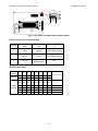
RJ‐45 Pinouts and Signals 32 Installation and Operation Manual (REV H) PVI 6500 / PVI 7500 As shown in the Figure 2.6.2, the RS‐232 signal pins, TXD and RXD, are in the RJ45‐L connector. Therefore, only the RJ45‐L can be used to connect to when the RS‐232 interface is selected If RS‐485 interface is selected, both RJ‐45 connectors will be used for the daisy‐chained/cascaded RS‐485 connections shown in the Figure 2.6.3. Standard Cables available for RS232 & 485 communication for PVI 3000 through PVI 7500 Description Part Number
Typical Use
Cable, RS485 comm. PVI 3000‐7500 WIH‐020082
RS485 cable for communication gateways Cable, RS485 daisy chain PVI 3000‐
WIH‐020081
RS485 jumper cable, for 3000‐7500 inverter‐to‐
7500 inverter Length
7 ft
30 in.
WIH‐020081 RS485 Daisy chain To gateway or computer WIH‐020082 Fig 2.6.3 RS‐485 connection Standard Ethernet patch cables are not compatible with the inverters, even though the inverters use RJ‐45 receptacles and require CAT5e cable, the pinouts are not the same as the Ethernet standard. 2.7 Communication ID adjustment The RS485 communication ID can be set by two ways. The first way is assign the address value (1‐254) by switching each of the switches on. The second way is setting by software, where all of the switches must be set to OFF (0) or ON (255) in which case the ID value will depend on an EEPROM parameter which can be changed by software tools via communication port. When using SolrenView data monitoring use an address between 1 and 16. SolrenView can automatically detect the ID# (see SolrenView manual). Each inverter requires a unique number when connected to a single communication DAS. 33 Installation and Operation Manual (REV H) PVI 6500 / PVI 7500 ON
OFF
1
8
Fig 2.7.1 DIP Switch for RS485 Communication Address Different ways to set communication ID ID Switch EEPROM setting
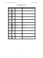
Condition (S201) (19) Communication ID 1 1~254 (ignore) Use ID Switch setting
2 0 or 255 1~255 Use EEPROM setting
3 0 or 255 0 or >255 or EEPROM error 255 ID Switch value (S201) NO. of
ID Switch
Weighting
1
2
3
4
5
6
7
8
bit 0 bit 1 bit 2 bit 3 bit 4 bit 5 bit 6 bit 7
1
2
4
8
16
32
64 128
OFF OFF OFF OFF OFF OFF OFF OFF
Example ON OFF OFF OFF OFF OFF OFF OFF
of Setup OFF ON OFF OFF OFF OFF OFF OFF
ON ON OFF OFF OFF OFF OFF OFF
ON ON ON ON ON ON ON ON
34 ID Switch value
0
1
2
3
255
Installation and Operation Manual (REV H) PVI 6500 / PVI 7500 3 Commissioning the Inverter and PV System Ensure that the inverter is mounted, all connections are made and you are ready to power it up before continuing with this section. NOTE: Make sure all tools, parts, etc. are removed from the vicinity of the inverter before turning it on. WARNING: Make a final check for correctness of all AC and DC wiring to the inverter and in the system. NOTE: With the PV modules connected and the inverter disconnect still in the off position, it is good practice to check PV polarity once more simply by carefully using a 600V, DC rated CAT III digital volt meter and probing the positive (+) and negative (‐) PV connections on the terminal blocks in the wiring box. Turning on the inverter for the first time: STOP! CHECK YOUR WIRING: WARNING! EXTREME SHOCK AND FIRE HAZARD! FAILURE TO FOLLOW THE FOLLOWING PROCEDURE CAN RESULT IN SERIOUS SHOCK, FIRE DAMAGE AND WILL VOID INVERTER WARRANTY! WARNING! ARC FLASH HAZARD! ALWAYS WEAR APPROPRIATE PERSONAL PROTECTIVE GEAR WHEN WORKING ON ENERGIZED CIRCUITS! o
o
o
o
o
REMOVE WIRING BOX COVER, Watch for live terminals and fuse holders. PV STRING FUSES SHOULD NOT BE INSTALLED AT THIS POINT (If they are installed, STOP! and see the section “Replacing PV Fuses” in the Maintenance section at the end of this manual) CHECK DC VOLTAGES OF ALL STRINGS USING 600V DC METER MEASURED VOLTAGES SHOULD BE OPEN CIRCUIT VOLTAGE; IF THE MEASURED VOLTAGE IS AT OR CLOSE TO 0.0V, THEN STOP! AND RECHECK YOUR WIRING TO ENSURE THERE IS NOT A DEAD SHORT. CHECK DC POLARITY OF ALL STRINGS USING 600V DC METER MEASURED VOLTAGES SHOULD INDICATE POSITIVE READINGS WHEN THE “RED” PROBE OF YOUR METER IS ON THE UNGROUNDED TERMINAL AND THE “BLACK” PROBE OF YOUR METER IS ON THE GROUNDED TERMINAL (except for positively grounded systems, in which case see Appendix D at the end of this manual). IF THE MEASURED VOLTAGES INDICATE A NEGATIVE POLARITY, THEN STOP! AND RECHECK YOUR WIRING TO ENSURE THE POLARITY OF THE STRINGS IS CORRECT. ONCE THE VOLTAGES AND POLARITIES ARE MEASURED AND CONFIRMED TO BE CORRECT, INSTALL THE PV STRING FUSES.
Unlock and turn on the dedicated 2‐pole circuit 240/208VAC circuit breaker on the home/building electrical panel (or 1‐
pole breaker for 277VAC)
Unlock and turn on the system AC disconnect (if the system is equipped with additional AC disconnect)
Turn on the DC/AC disconnect on the inverter.
Watch the LED indicators for initialization (all three LEDs on) and LCD messages. 35 Installation and Operation Manual (REV H) PVI 6500 / PVI 7500
Watch for blinking green LED and LCD messages indicating a 5‐minute connect to grid countdown. Following this time, the inverter will come on‐line and begin to feed power into the AC circuit.
Lastly, look for a steady green LED, indicating the inverter is now operating at the Maximum Power Point of the array. See LCD section (4) of manual for detailed description of messages and indications. Operation: The control electronics will be active as soon as DC (PV) voltage reaches 200VDC. The inverter will connect to the utility/building grid when the DC voltage first exceeds 260VDC (strike voltage). Next, the inverter will load the array, bringing the DC voltage down from 260VDC to no less than 230VDC. Once there is enough PV power at 230VDC to feed back AC power, the inverter will automatically start to do so. Operating states, GFDI status and error indications shown by the LED indicators, as well as LCD data, mode and error codes are described in chapter 4, “Power, GFDI, Error LED Indicators and LCD Display”. 36 Installation and Operation Manual (REV H) PVI 6500 / PVI 7500 4 Power, Ground Fault, Error LED Indicators and LCD Display The inverter operates automatically without the need for user interaction or maintenance. The PVI 6500‐7500 automatically starts feeding AC power into the grid every morning as the sun rises, as soon as sufficient DC voltage and PV power is available. The inverter microcontroller runs through various checks before going online with the grid and feeding power into the grid. 4.1 Power, Ground Fault and Error LED Indicators There are three light‐emitting diodes (LEDs) mounted on the front of the inverter to show the operating condition of the inverter (to the right of the LCD display). Fig. 4.1.1 Power, Error, and Ground Fault Indicator LEDs and LCD Display The green LED "Power" shows the current operating condition. The yellow LED "Error" indicates whether there is an internal or external fault present and whether the AC grid back‐feed has been interrupted. The red LED "Ground Fault" shows if a ground fault is present. Description of LED symbols used to indicate LED status in this manual ○
●
x ☼
LED ON LED OFF Not relevant / Inconsequential LED ON 0.9 second/OFF 0.1 Second ¤
LED ON 0.1 second/OFF 0.9 Second LED ON 0.25 second/OFF 0.25 Second 37 Installation and Operation Manual (REV H) PVI 6500 / PVI 7500 LED Indication Table LED indicators Green Yellow Red Green Yellow Red Green Yellow Red Green Yellow Red Green Yellow Red Green Yellow Red Green Yellow Red Green Yellow Red Green Yellow Red Green Yellow Red Green Yellow Red Operating status Initialization Description The PVI 6500‐7500 is initializing. System Check mode The inverter is in System Check mode. Monitor mode The inverter is in Monitoring mode. Grid/MPP mode
The inverter is feeding power back to the grid. Power Limit mode. Power Limit Warning Warning is detected. Low Insolation (solar irradiation) The inverter is in low insolation (solar irradiation). Fault mode
The inverter is in Fault mode. Ground Fault
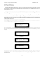
A DC ground fault was detected. Idle mode The inverter is in idle mode. Night Time There is no DC power coming from PV array. System is powered off. 38 Installation and Operation Manual (REV H) PVI 6500 / PVI 7500 4.2 The LCD Display The PVI 6500‐7500 is supplied ready to operate. There are no user settings, which need to be made before power can be fed back into the grid. The device comes with a standard LCD display on which various data can be read. All LCD display values have accuracy tolerances of up to 5%. The PVI 6500‐7500 has a 16 x 2 LCD to show the operating status, input/output data, and system messages. As long as the DC input voltage is above the preset threshold value, the LCD continues to display the information following the process flow illustrated in the Figure 4.2.1. The process flow may follow the operating mode, fault mode, or idle mode. The operating mode is when the system goes from power‐on to system check, monitoring, and then grid feeding mode without any fault condition detected. If a fault condition that cannot be automatically be cleared is being detected during system check and monitoring mode, the system will wait in the fault mode until the fault condition goes away. If a fault does not get cleared on its own, then the system will enter the idle mode and will need a service person to clear the fault and manually reset the system. These three modes are illustrated in Figure 4.2.1 later in this section. The following figures explain how the display works in the operating mode. When the DC input voltage goes above the pre‐set threshold value, the inverter is powered up and will show the manufacturer’s name and model (PVI 7500 in this example) on the LCD as shown below. S O L E C T R I A
P V I
7 5 0 0
After 3 seconds, software versions of two embedded CPU’s, Sequential and Current controllers, will be displayed on the LCD. Next in the boot‐up sequence, the serial number (S/N), the baud rate (BR) / address (ID) for the communication port will be displayed. S E Q
V e r s i o n
X . XX
C UR
V e r s i o n
X . XX
3 seconds ↓ C h e c k s u m
XXXXXXX
3 seconds ↓ S / N
B R
XXXXXXXXXXXX
XXXXX
I D
XXX
3 seconds ↓ Three (3) seconds later, the inverter displays the setting of the nominal grid voltage configuration. The grid type setting of 208/240/277 with neutral is used as the display example shown below. For the grid type setting, please refer to section 2.3 “Wiring the Inverter”. 39 Installation and Operation Manual (REV H) PVI 6500 / PVI 7500 G r i d
L 1
Ty pe
12 0V
L 2
1 20 V
3 seconds ↓ If the grid type is set to 240 VAC without neutral, then the display will be looked as the figure shown below. G r i d
T y pe
L 1 - L 2
2 4 0 V
3 seconds ↓ Three (3) seconds later, the LCD will show the voltage setting for the inverter to drop the grid connection. The settings of the Vl‐
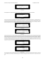
nH and its clearing time will be displayed. The Vl‐nH setting is the phase‐to‐neutral (rms) high threshold voltage setting at which point the inverter disconnects its output from the AC power grid when abnormally high phase‐to‐neutral AC voltage is detected. After the setting of the Vl‐nH is displayed, the setting of the Vl‐nL will be displayed for 3 seconds. V l - n H
C l r
t
XXX . XV
<
XXX
C y c s
3 seconds ↓ V l - n L
C l r
t
XXX . XV
<
XXX
C y c s
3 seconds ↓ Three (3) seconds later, the inverter displays the setting of the VacH which is the phase‐to‐phase (rms) high threshold voltage setting at which point the inverter disconnects itself from the grid when abnormally high phase‐to‐phase AC voltage is detected. Also, the setting of the clearing time which is the total duration of time to disconnect the output from the AC grid is displayed. This delay is necessary to avoid nuisance trips. After the settings of the VacH and its clearing time, the settings of the VacL and its clearing time will be displayed for three (3) seconds. The display Vl‐nH/Vl‐nL is only for 208/240/277VAC with neutral setting, VacH/VasL is only for 240 or 208 without neutral, they would not display at the same time. V a c H
C l r
XXX . XV
t
<
XXX
C y c s
3 seconds ↓ V a c L
C l r
XXX . XV
t
<
XXX
C y c s
3 seconds ↓ Then the high and low threshold settings of the AC frequency and the associated clearing time will be shown for three (3) seconds. When the AC frequency exceeds the high or low threshold setting, the inverter will disconnect its output from the AC grid. 40 Installation and Operation Manual (REV H) PVI 6500 / PVI 7500 F a c H
C l r
XX . XXH z
t
<
XXX
C y c s
3 seconds ↓ F a c L
C l r
XX . XXH z
t
<
XXX
C y c s
3 seconds ↓ Then the LCD will display the setting of the AC high voltage limit above which value, the inverter will reduce the output power until the AC voltage drops within this setting. If the grid type is set to 208/240/277VAC with neutral, the display will appear as shown below. V
c H
L i m i t
L - N
XXX . XV
3 seconds ↓ Then, the setting of the reconnection time will be displayed. The reconnection time is the duration of delay time for the inverter to reconnect to the grid after the fault(s) is(are) cleared. V p v S t a r t
XXX . XV
R e c o n n e c t
XXX s
3 seconds ↓ System Check mode After the basic information of the inverter is displayed, the system enters the System Check mode which is indicated on the LCD. M o d e
S y s t e m
C h e c k i n g
During the system checking, if the DC input voltage does not reach the point of the PV start voltage setting, then the following message will be shown on the LCD. The system will stay in this state until the PV start voltage is reached. L o w
I n s o l a t i o n
If the grid is not connected during the system check, the inverter enters the fault mode and the following message will be shown on the LCD. M o d e
G r i d
F a u l t
NA
41 Installation and Operation Manual (REV H) PVI 6500 / PVI 7500 Monitoring Mode Once system check is completed, the inverter goes into the monitoring mode. Even if all measurements needed for grid feeding are in the acceptable range, the system will keep monitoring these measurements for a period of time. The following information tells users that the system will go into the grid feeding mode in XXX seconds and then show the measured data of the DC input voltages and the existing voltage and frequency on the grid side. M o d e
Mo n i t o r i ng
N e x t C o n n e c t
XXX s
3 seconds ↓ Vp v
XXX
V
3 seconds ↓ V a c
XXX . XV
F a c
XX . XH z
3 seconds ↓ If the DC voltage falls under the PV start voltage, during the monitoring mode, the system stays in this mode and shows the information as follows. The system will still keep measuring the parameters of both DC and AC and displaying them on the LCD. M o d e
Mo n i t o r i n g
L o w
I n s o l a t i o n
3 seconds ↓ V p v
XXXV
3 seconds ↓ V a c
XXX . XV
F a c
XX . XH z
3 seconds ↓ If measurements stay within acceptable range the system enters the grid feeding mode; the LCD will show the following information in the given order and repeat this until the system goes to another operating mode. The first screen shows the current operation mode. 42 Installation and Operation Manual (REV H) PVI 6500 / PVI 7500 M o d e
G r i d / MP P
3 seconds ↓ The first two messages are about the PV array and output voltages and power. Vpv is the incoming DC voltage from the PV array. Wpv is the incoming power of the PV array in Watts. Vac, Pac, Iac, and Fac are the voltage, power, current, and frequency at the inverter output. V p v
XXXV
Wp v
X X X XW
3 seconds ↓ V a c
XXX . XV
P a c
X X X XW
3 seconds ↓ F a c
XX . XH z
I a c
XX . XA
3 seconds ↓ The next message shows the accumulated energy in kWh and number of running hours since the inverter has been powered on for the day. E t o d a y
XXX . X
H t o d a y
XX . X
kWh
H r
3 seconds ↓ The next message shows the total accumulated energy in kWh and period of time in hours since the inverter has been installed and operated for the first time. E a c
H
XX XXXX . X
XXXXX
kWh
H r
3 seconds ↓ Power Derating Message There are five possible derating messages which will be shown if the power is derated during grid feeding mode. Only one de‐
rating cause is displayed at a time. When “Temp” message is present, the power derating is caused by an over temperature of the heat sink. The “Ipv” message shows that the power derating is caused by restricting the DC input current to the maximum limit. The “Iac” and “Pac” messages illustrate the power derating is caused due to a restriction of the maximum output AC current and power. The “VacH” message shows that the power derating is caused by high AC voltage. 43 Installation and Operation Manual (REV H) PVI 6500 / PVI 7500 M o d e
D e r a t i n g
T e m p
M o d e
D e r a t i n g
I p v
M o d e
D e r a t i n g
I a c
M o d e
D e r a t i n g
P a c
M o d e
D e r a t i n g
V a c H
Warning Messages
There are three possible warning messages that may be displayed to indicate failures. These messages can only occur in grid feeding mode. When EEPROM message is displayed, the system is unable to access the EEPROM. The COMM message means a failure of the communication function. The FAN BLOCK message shows that the fan has stopped running. These warnings could appear one after the other. Call the Solectria Renewables customer service hotline for resolution. W a r n i n g
E E P R OM
W a r n i n g
C O MM
W a r n i n g
FA N
B L OC K
44 Installation and Operation Manual (REV H) PVI 6500 / PVI 7500 Fault Mode The fault mode messages are as follows. Fault mode, serial number of the inverter, software versions of the sequential and current controllers are shown and then the error messages which are listed in the Error Message Table in the Troubleshooting section 5, Mo d e
S / N
F a u l t
XXXXXXXXXXXX
3 seconds ↓ S E Q
V e r s i o n
X . XX
C UR
V e r s i o n
X . XX
3 seconds ↓ M o d e
e r r o r
F a u l t
m e s s a g e
3 seconds ↓ There are several error messages that show the detailed conditions that can cause the system to go into the fault mode, such as the messages shown below that show that the frequency of the AC grid is too high (H) or too low (L). After three (3) seconds, the message shows the present frequency and the frequency that caused the system to go into the fault mode. M o d e
F a u l t
F a cX
X: H or L 3 seconds ↓ T r i p
a t
XX . XH z
P r e s e n t
XX . XH z
3 seconds ↓ The message below shows that the AC voltage is too high (H) or too low (L) and next the inverter displays the AC voltage limit as well as the present AC grid voltage measurement. M o d e
F a u l t
V a cX
X: H or L 3 seconds ↓ 45 Installation and Operation Manual (REV H) PVI 6500 / PVI 7500 T r i p
a t
XXX . XV
P r e s e n t
XXX . XV
3 seconds ↓ The message below shows the PV DC voltage is too high. M o d e
F a u l t
V p v H
3 seconds ↓ T r i p
a t
XXX . XV
P r e s e n t
XXX . XV
3 seconds ↓ The following message presents that the AC line1 and/or line2 voltage (referenced to the neutral) is/are too high (H) or too low (L). M o d e
F a u l t
V a c L 1
X
V a c L 2
X
X: H or L 3 seconds ↓ Idle Mode The idle mode messages are as follows. Operating mode, serial number of the inverter, software versions of the sequential and current controllers are shown and then the error messages which are listed in the Error Message Table in section 5. M o d e
S / N
I d l e
XXXXXXXXXXXX
3 seconds ↓ S E Q
V e r s i o n
X . XX
C UR
V e r s i o n
X . XX
3 seconds ↓ M o d e
e r r o r
I d l e
m e s s a g e
46 Installation and Operation Manual (REV H) PVI 6500 / PVI 7500 SOLECTRIA
PVI7500
Fig 4.2.1 PVI 6500‐7500 inverter LCD display flow‐chart 47 Installation and Operation Manual (REV H) PVI 6500 / PVI 7500 5 Troubleshooting 5.1 Diagnosis and analysing data Identifying and resolving faults The PVI 6500‐7500 is fitted with a self‐diagnostic system, which can recognize the majority of possible faults and show these on the display. This allows the operator to rapidly identify possible problems in the solar inverter or PV system. Please refer to the LCD section (4) for a thorough explanation of fault codes, modes, etc. Ground Fault: If a significant ground fault occurs in the PV array or wiring, the GFDI fuse (located in the wiring box) may be blown. If it is, locate and repair the ground fault and only then replace the fuse with Bussmann KLKD1 (1 Amp, 600VDC). Call the Solectria Renewables customer service hotline for assistance with locating a DC ground fault in the array or conduits. If the GFDI detects a ground fault, the Ground Fault LED will light and the “fault” will be displayed. Weak Sunlight Condition: Operation in weak sunlight, (for example early in the morning, when overcast or when snow is covering most or all of the PV array) can cause the inverter to go through a cycle of trying to start and restart several times. This can occur if the array reaches 260V (strike voltage) but there is nearly no power available. 5.2 Explanations of Error Messages In the event of a fault, the inverter will stop feeding the AC voltage to the building/utility and display the error message on the LCD. Qualified service personnel shall do the analysis, measurement, and debug the system. It is recommended to analyze the fault condition(s) by referring to the table below and then remove the fault condition(s) in order to return the inverter to a normal state and continue to feed AC power to the utility. Please contact Solectria Renewables customer service hotline if the error message does not clear. WARNING: Certain trouble shooting steps may require work on energized and exposed circuits, only qualified personnel should perform these tasks. Please use Personal Protective Gear when measuring voltage in the inverter. Error Message Table Error Message GridNA Description
No AC voltage is detected.
Drift Fac Islanding is detected. VacH The AC voltage of utility is above the upper limit. 48 Possible Solutions ‐ Verify AC voltage disconnect is on ‐ Verify AC circuit breaker is on/operational ‐ Verify and measure AC voltage present in Inverter disconnect ‐ Contact installing company or Solectria Renewables ‐ Verify AC voltage present and correct in Inverter disconnect ‐ Contact installing company or Solectria Renewables ‐ Verify setting for S201 is correct for the grid voltage applied ‐ Measure the AC voltage and compare to the voltage on the inverter display ‐ Contact Solectria Renewables for Installation and Operation Manual (REV H) PVI 6500 / PVI 7500 VacL The AC voltage of main utility is below the lower limit. FacH The frequency of AC voltage of the utility is above the upper limit. FacL The frequency of AC voltage of the utility is below the lower limit. VpvH The DC voltage of PV array is above the upper limit. Imax_AC Over current on the AC side.
InvTempMax The internal temperature of the inverter exceeded the safe operating limit. Relay Open Relay Close VacL1 H Relay test failed. The voltage between L1 and neutral is over the upper limit. VacL1 L The voltage between L1 and neutral is under the lower limit. VacL2 H The voltage between L2 and neutral is over the upper limit. 49 assistance if the range needs to be adjusted ‐ Verify setting for S201 is correct for the grid voltage applied ‐ Measure the AC voltage and compare to the voltage on the inverter display ‐ Contact Solectria Renewables for assistance if the range needs to be adjusted ‐ Measure the frequency and compare to the frequency on the display ‐ Contact Solectria Renewables for assistance if the range needs to be adjusted ‐ Measure the frequency and compare to the frequency on the display ‐ Contact Solectria Renewables for assistance if the range needs to be adjusted ‐ Turn off the inverter disconnect ‐ Measure the VDC at the Inverter disconnect if over 599VDC the solar array needs to be inspected ‐ Contact installing company ‐ Do not turn on the inverter until the condition is repaired ‐ The inverter will continue to operate at a lower current ‐ If message occurs frequently contact the installing company ‐ If the inverter is located in direct sunlight it may need to be shaded ‐ The VDC input may be too high causing increased temperature, reduce VDC input. ‐ Contact installing company or Solectria Renewables ‐ Contact installing company or Solectria Renewables ‐ Verify setting for S201 is correct for the grid voltage applied ‐ Measure the AC voltage and compare to the voltage on the inverter display ‐ Contact Solectria Renewables for assistance if the range needs to be adjusted ‐ Verify setting for S201 is correct for the grid voltage applied ‐ Measure the AC voltage and compare to the voltage on the inverter display ‐ Contact Solectria Renewables for assistance if the range needs to be adjusted ‐ Verify setting for S201 is correct for the grid voltage applied ‐ Measure the AC voltage and compare to the voltage on the inverter display ‐ Contact Solectria Renewables for Installation and Operation Manual (REV H) PVI 6500 / PVI 7500 VacL2 L The voltage between L2 and neutral is under the lower limit. MOV Fault, AC High voltage protection function failed on the AC side. High voltage protection function failed on the DC side. The GFDI Fuse is open or blown.
MOV Fault, DC GFDI DCInjectCurH Internal COMM Watchdog Too much DC current injected into the AC grid is detected. Internal DC bus voltage is above the upper limit. Internal communication failed.
Internal watchdog function triggered.
Idc Test Offset check for grid monitoring failed
Offset Temp. Sensor The DC injection current monitoring function failed. Offset check for grid monitoring failed.
RAM Test The internal temperature sensor failed. EEPROM Test Memory failed System Error EEPROM test failed.
Version Error The system failed. CPU Delta Fac CPU Delta Vac CPU Delta GFDI CPU Delta Idc The firmware version is not correct.
Internal measurement comparison error or defective hardware VdcbusH 50 assistance if the range needs to be adjusted ‐ Verify setting for S201 is correct for the grid voltage applied ‐ Measure the AC voltage and compare to the voltage on the inverter display ‐ Contact Solectria Renewables for assistance if the range needs to be adjusted ‐ Verify MOV appearance is OK ‐ Contact Solectria Renewables ‐ Verify MOV appearance is OK ‐ Contact Solectria Renewables ‐ Use DMM to verify GFDI is open
contact installing company to inspect and repair the array ‐ Replace fuse with same type and rating ‐ Turn off the inverter and restart. ‐ If the error re‐occurs Contact installing company or Solectria Renewables ‐ Turn off the inverter and restart. ‐ If the error re‐occurs Contact installing company or Solectria Renewables ‐ Turn off the inverter and restart. ‐ If the error re‐occurs Contact installing company or Solectria Renewables ‐ Turn off the inverter and restart. ‐ If the error re‐occurs Contact installing company or Solectria Renewables ‐ Turn off the inverter and restart. ‐ If the error re‐occurs Contact installing company or Solectria Renewables ‐ Turn off the inverter and restart. ‐ If the error re‐occurs Contact installing company or Solectria Renewables ‐ Turn off the inverter and restart. ‐ If the error re‐occurs Contact installing company or Solectria Renewables ‐ Turn off the inverter and restart. ‐ If the error re‐occurs Contact installing company or Solectria Renewables ‐ Turn off the inverter and restart. ‐ If the error re‐occurs Contact installing company or Solectria Renewables ‐ Turn off the inverter and restart. ‐ If the error re‐occurs Contact installing company or Solectria Renewables ‐ Turn off the inverter and restart. ‐ If the error re‐occurs Contact installing company or Solectria Renewables ‐ Turn off the inverter and restart. ‐ If the error re‐occurs Contact installing company or Solectria Renewables Installation and Operation Manual (REV H) PVI 6500 / PVI 7500 GFDI HW Error GFDI detect hardware failure
IpvH Over current on the DC side Driver Fault Driver circuit or power device failed
CalDataError Calibration data is out of range
CalDataLoss Calibration data is lost.
Ibuck Over Internal converter over current
Converter Error DC/DC hardware failed.
‐ Turn off the inverter and restart. ‐ If the error re‐occurs Contact installing company or Solectria Renewables ‐ Use a suitable meter for measuring the current from the array. ‐ Verify the current is within the limits for the inverter. ‐ Contact the installing company to check the array ‐ Turn off the inverter and restart. ‐ If the error re‐occurs Contact installing company or Solectria Renewables ‐ Turn off the inverter and restart. ‐ If the error re‐occurs Contact installing company or Solectria Renewables ‐ Turn off the inverter and restart. ‐ If the error re‐occurs Contact installing company or Solectria Renewables ‐ Turn off the inverter and restart. ‐ If the error re‐occurs Contact installing company or Solectria Renewables ‐ Turn off the inverter and restart. ‐ If the error re‐occurs Contact installing company or Solectria Renewables ‐ String sizing design provides too low DC voltage at high module temperature ModuleTempMax Module temperature high
5.3 Maintenance: Replacing the GFDI Fuse Before replacing the fuse, you must switch off the DC/AC disconnect switch and AC breaker and wait for at least 5 minutes for system to discharge. Verify the absence of voltage with a voltmeter. Remove the cover of the inverter wiring box and remove the GFDI fuse holder by pulling the holder towards you and then replace the GFDI fuse with the same type and rating (600VDC, 1A). 1.
2.
3.
4.
Turn OFF all DC/AC disconnect switches and AC breaker Wait for at least 5 minutes Exchange the GFDI fuse Turn ON all DC/AC disconnect switches and AC breaker Fig 5.3.1 Replacement of the GFDI fuse holder 51 Installation and Operation Manual (REV H) PVI 6500 / PVI 7500 WARNING! For continued protection against risk of fire, replace only with the same type and ratings of fuse (600 VDC, 1A)! Replacing the PV String Fuses The inverter is shipped with five (5) 15A, 600Vdc PV string fuses for PV strings. However, the size of the PV string fuse is determined by the electrical ratings of the PV module and by UL and code requirements. The minimum size of the PV string fuse is calculated using the short circuit current rating (Isc) of the PV module. Please be sure to consult with the PV module manufacturer for appropriate PV string fuse rating. IN NO CASE SHALL FUSES OF LARGER THAN 20A BE USED IN THE PV STRING FUSE HOLDER. Replacing PV Fuses STOP! WARNING! EXTREME SHOCK AND FIRE HAZARD! FAILURE TO FOLLOW THE FOLLOWING PROCEDURE CAN RESULT IN SERIOUS SHOCK, FIRE DAMAGE AND WILL VOID INVERTER WARRANTY! o REMOVE WIRING BOX COVER o CHECK DC VOLTAGES OF ALL STRINGS USING 600V DC METER MEASURED VOLTAGES SHOULD BE OPEN CIRCUIT VOLTAGE; IF THE MEASURED VOLTAGE IS AT OR CLOSE TO 0.0Vdc, THEN STOP! AND DO NOT REMOVE ANY FUSES. RECHECK YOUR WIRING TO ENSURE THERE IS NOT A DEAD SHORT OR A STRING WITH REVERSED POLARITY. o CHECK DC CURRENT OF ALL STRINGS USING CLAMP‐ON DC METER MEASURED CURRENTS SHOULD BE AT OR VERY CLOSE TO 0.0Adc. IF THERE IS A MEASURED CURRENT READING, THEN STOP! AND DO NOT REMOVE ANY FUSES. RECHECK YOUR WIRING TO ENSURE THERE IS NOT A DEAD SHORT OR A STRING WITH REVERSED POLARITY. o ONCE THE VOLTAGES AND CURRENTS ARE MEASURED AND CONFIRMED TO BE CORRECT, REMOVE AND REPLACE THE PV STRING FUSES. NEVER REMOVE A DC FUSE UNDER CURRENT! REMOVING A DC FUSE UNDER CURRENT CAN RESULT IN INJURY AND WILL DAMAGE THE WIRING BOX. Fig 5.3.2 Replacement of the PV string fuses 52 Installation and Operation Manual (REV H) PVI 6500 / PVI 7500 WARNING! PV arrays are always energized when exposed to light therefore hazardous voltage is still present on the terminal blocks and the PV string fuse holders even when the DC/AC disconnect switch is switched OFF. Please cover the PV arrays with opaque materials during PV string fuse replacement. !
5.4 CAUTION! The string fuse size must not be greater than the maximum fuse size rating of the PV module provided on the PV module manufacturer data sheet. If no maximum fuse size is indicated, please contact the PV module manufacturer. Factory Service Please contact Solectria Renewables customer service hotline for our documentation on removing and replacing the top inverter section (while leaving wiring box in place). 5.5 Inverter Replacement Once the product is diagnosed and Solectria determines that it requires Factory Service, the product can be removed and sent back using the original shipping box and packing materials. A copy of the RMA number must be included in the package. Documentation: There is some documentation that must be provided with the returned product. Please include as much detail as possible. 1. Serial number and part number of the inverter 2. Brief description of system it has been used in and failure circumstances (string sizing, events prior to failure) 3. Fault message on LCD display or fault condition that occurred 4. Can the failure be reproduced? How? The following sections will describe the steps to remove and subsequent reinstall the inverter with the wiring box remaining on the wall. 5.5.1 Remove the Inverter The PVI 6500/7500 inverter is designed to be easily separated from the wiring box and removed from the mounting bracket. You must wait for at least five (5) minutes for system to discharge after DC/AC disconnect switch and breakers are switched OFF and locked out before opening the front cover of the inverter to disconnect the wires. Verify the absence of voltage with a voltmeter. Both DC and AC wires that are disconnected from the inverter must be properly terminated with insulating means. After the inverter is removed from the mounting bracket, the holes that the wires on top of the wiring box go through must be covered with the cover plate that is attached at the back of the wiring box to prevent the box from water intrusion, as shown in the figure 5.5.1.7. WARNING! PV arrays will be energized when exposed to light. Cover the arrays with opaque material during installation and wiring. Verify the absence of voltage with a DC voltmeter. WARNING! Reconfirm that the circuit breaker to the main utility is switched OFF and locked out before disconnecting the power cable from the breaker to the AC terminal block. Verify the absence of voltage with an AC voltmeter. 53 Installation and Operation Manual (REV H) PVI 6500 / PVI 7500 Fig 5.5.1.1 Remove the cover of the Inverter J504
DC wires
Disconnect
switch
AC wires
J506
Fig 5.5.1.2 Remove the DC and AC wires 54 Installation and Operation Manual (REV H) PVI 6500 / PVI 7500 Fig 5.5.1.3 Remove the nuts attaching the inverter and wiring box Fig 5.5.1.4 Remove the attachment screws on the sides of the inverter Fig 5.5.1.5 Remove the inverter carefully from the hangers on mounting bracket 55 Installation and Operation Manual (REV H) PVI 6500 / PVI 7500 Back View
Fig 5.5.1.6 Position the cover plate and fasten the screws 56 Installation and Operation Manual (REV H) PVI 6500 / PVI 7500 Fig 5.5.1.7 Position the cover plate and fasten the screws 1. 2. 3. 4. Turn the DC/AC disconnect switch to OFF position and turn off and lock out all breakers. Wait for at least 5 minutes. Remove the cover of the wiring box by following the steps described in section 2.3, as shown in the figure 5.5.1.1. Disconnect the red and black DC wires from the disconnect switch and J505 terminal. Disconnect the red, black and white AC wires from the disconnect switch and J506 terminal as shown in figure 5.5.1.2. 5. All disconnected wires must be wrapped with insulating materials to prevent electric shock. Place the disconnected wires inside the wiring box. 6. Loosen the 4 nuts with a 13‐mm wrench as shown in the figure 5.5.1.3. 7. Remove the screws bonding the sides of the inverter so that the inverter can be taken apart from the wiring box as shown in the figure 5.5.1.4. 8. Remove the inverter from the mounting bracket as shown in the figure 5.5.1.5. 9. Use the cover plate that is on top of the wiring box to cover the through holes of the wires with the 4 nuts as show in the figure 5.5.1.6. 10. Put the front cover of the wiring box back and fasten the screws as shown in the figure 5.5.1.7. 11. Collect the removed screws in a plastic bag and place aside for reinstalling the inverter in the future. 12. Keep the DC/AC disconnect switch and circuit breakers locked in the OFF position until the inverter is reinstalled, all wires are connected correctly, front covers are replaced and screws are fastened. 5.5.2 Reinstall the Inverter After reinstallation of the inverter, all wires must be reconnected correctly before the inverter can be returned to service. WARNING! PV arrays will be energized when exposed to light. Cover the arrays with opaque material during installation and wiring. Verify the absence of voltage with a DC voltmeter. WARNING! Reconfirm that the circuit breaker to the main utility is switched OFF before connecting the power cable from the breaker to the AC terminal block. Verify the absence of voltage with an AC voltmeter. 57 Installation and Operation Manual (REV H) PVI 6500 / PVI 7500 Back View
Fig 5.5.2.1 Re‐install the cover plate and attach it at the back of the wiring box 58 Installation and Operation Manual (REV H) PVI 6500 / PVI 7500 Fig 5.5.2.2 Hang the inverter on the mounting bracket carefully Fig 5.5.2.3 Fasten the screws at the sides of the inverter 59 Installation and Operation Manual (REV H) PVI 6500 / PVI 7500 Fig 5.5.2.4 Fasten the nuts that attach the inverter and wiring box Fig 5.5.2.5 Connect the AC and DC wiring to their correct terminals 60 Installation and Operation Manual (REV H) PVI 6500 / PVI 7500 Fig 5.5.2.6 Put the wiring box cover back on Fig 5.5.2.7 Fasten the cover screws then 1. Verify that DC/AC disconnect switches and breakers are turned off and locked out. Verify the absence of voltage with a voltmeter. 2. Remove the front cover of the wiring box by following the steps described in section 2.3. 3. Remove the cover plate used to cover the through holes of the wires and put it back to its original place as shown in the figure 5.5.2.1. 4. Hang the inverter on the mounting bracket as shown in the figure 5.5.2.2. 5. Fasten the bonding screws with a torque of 1.7Nm (15.6 in‐lb) to the sides of the inverter as shown in the figure 5.5.2.3. 6. Fasten the attachment nuts with a torque of 5.88 Nm (51.96 in‐lb) between the inverter and the wiring box for solid support and ground bonding as shown in the figure 5.5.2.4. 7. Tighten the nuts with a torque of 1.7Nm (15.6 in‐lb) when performing steps 8 and 9. 8. For the AC wire connections, connect the WHITE AC wire to the J506 “WHITE” terminal. If it is originally 208 / 240 V system, then connect the RED, BLACK AC wire to the disconnect switch. If it is originally 277 V system, then connect the RED wire to the disconnect switch and connect the BLACK AC wire to the J506 “BLACK for 277V” terminal. Please refer to section 2.3 for further details. 9. In a negatively grounded system, connect the RED DC wire to the disconnect switch and connect the BLACK DC wire to the J505 terminal as shown in the figure 2.5.1.1. If the system is positively grounded, connect the red DC wire to the J505 terminal and connect the black DC wire to the disconnect switch as shown in the figure D.1. Please refer to the section 2.3.2 for further details. 10. Put the covers of the wiring box back as shown in the figure 5.4.3.2.6. Fasten the screws as shown in the figure 5.5.2.7. 11. Unlock Turn ON the DC/AC disconnect switch and breakers while wearing personal protective equipment. 61 Installation and Operation Manual (REV H) PVI 6500 / PVI 7500 6 Product Warranty & RMA Policy
6.1 Warranty Policy
The Solectria Renewables Warranty Policy is stated below.
Solectria Renewables Warranty Coverage:
Solectria Renewables Limited Warranties are provided by Solectria Renewables, LLC. ("Solectria Renewables") and cover
defects in workmanship and materials. Solectria Renewables’ price for the products is based on inclusion of these limited
warranty provisions and disclaimers. In the event of a conflict between the terms of this Limited Warranty and any terms and
conditions proposed by purchasers of Solectria Renewables’ products, these Limited Warranty provisions shall govern the parties’
obligations with respect to warranty coverage for defective products.
Duration of a Solectria Renewables Warranty Period:
The warranty period is 60 months from the date of purchase of the PVI 6500-7500 Inverter by the end user or 64 months after the
delivery date from Solectria Renewables to distributor or dealer/installer, whichever is shorter. If a warranty extension has been
purchased, the term is defined as extension beyond 60 months. For example, if a 5-year extension (to 10 years total) is purchased,
the term becomes 120 months from date of purchase.
If Solectria Renewables repairs or replaces a product, its warranty continues for the remaining portion of the original Warranty
Period or 90 days from the date of the return shipment to the customer, whichever is greater.
Solectria Renewables obligation to repair or replace a defective product under this warranty is contingent upon Solectria
Renewables receiving full and timely payment for the warranted products and associated shipping. Solectria Renewables
Warranty Coverage is voidable, at Solectria Renewables’ sole option, if full payment for products and associated shipping is not
received in full and in a timely manner by Solectria Renewables. Please contact Solectria Renewables Customer Service for
further details on other products.
What will Solectria Renewables do?
Solectria Renewables will, at its sole option, repair or replace the defective product free of charge, provided that you notify
Solectria Renewables of the product defect within the Warranty Period for your product, and provided that Solectria Renewables,
through inspection, establishes the existence of such a defect and that it is covered by the Limited Warranty.
Solectria Renewables will, at its sole option, use new and/or reconditioned parts in performing warranty repair and building
replacement products. Solectria Renewables reserves the right to use parts or products of original or improved design in the repair
or replacement. All replaced products and all parts removed from repaired products become the property of Solectria Renewables.
Solectria Renewables will attempt to repair the unit within a reasonable time period (there is no reimbursement for lost energy
production.)
For three-phase inverters 10kW and higher:
Solectria Renewables covers parts, travel and labor necessary to repair the product and shipment of parts to and from the customer
via a Solectria Renewables-selected non-expedited surface freight within the contiguous United States, Canada and Mexico. For
Alaska, Hawaii and all other installation locations Solectria Renewables will supply necessary parts as needed for warranty
repairs; however labor and travel are not included. Contact Solectria Renewables customer service for details on freight policy for
return shipments outside of the contiguous United States and Canada.
For single-phase inverters 7.5kW and lower:
Solectria Renewables covers replacement inverters or parts necessary to repair the product and shipments of parts to and from the
customer via a Solectria Renewables-selected non-expedited surface freight within the contiguous United States, Canada and
Mexico. For Alaska, Hawaii and all other installation locations Solectria Renewables will cover the cost of return shipment of
product one way from the customer.
62 Installation and Operation Manual (REV H) PVI 6500 / PVI 7500 The warranty does not include customs fees, broker fees or other taxes that may be imposed by the government agency. Contact
Solectria Renewables customer service for details on freight policy for return shipments outside of the contiguous United States
and Canada.
In the event an extended warranty option has been purchased, this extended warranty only applies to exposed outdoor locations
(defined as rooftop or open/unprotected locations) if the product has been purchased to include the gasket-sealed AC and DC
disconnect option or has a protective cover around 3 sides of inverter unit (back and sides) and over the top, 4"-60" away from
back and top and 30"-96" from sides.
Obtaining Service:
If your product requires troubleshooting or warranty service, contact your distributor or dealer/installer. If you are unable to
contact your distributor or dealer/installer, or the distributor or dealer/installer is unable to provide service, contact Solectria
Renewables directly at the number listed on the website in the customer service section for your product.
Solectria Renewables may send personnel to a jobsite or contract with an area technician, installer or other authorized, trained
service personnel to service/replace components.
Reimbursement for contracted services: Solectria Renewables will submit a purchase order to the designated service personnel
before work is performed. This purchase order will cover time expected for the required service and most likely an allocation for
travel time.
Direct returns may be performed according to the Solectria Renewables Return Material Authorization Policy.
In any warranty claim, dated proof of purchase must accompany the product and the product must not have been disassembled or
modified without prior written authorization by Solectria Renewables.
Proof of purchase may be in any one of the following forms:
- The dated purchase receipt from the original purchase of the product at point of sale to the end user, or
- The dated distributor or dealer/installer invoice or purchase receipt showing original equipment manufacturer (OEM) status, or
- The dated invoice or purchase receipt showing the product exchanged under warranty.
Solectria Renewables provides technical assistance Monday-Friday, 8:30am-7pm EST and on call technical support is provided
before and after business hours.
What does the Solectria Renewables warranty not cover?
Solectria Renewables Limited Warranties do not cover normal wear and tear of the product or costs related to the removal,
installation, or troubleshooting of the customer's electrical systems. These warranties do not apply to and Solectria Renewables
will not be responsible for any defect in or damage to:
a)
The product, if it has been misused, neglected, improperly installed, physically damaged or altered, either internally or
externally, or damaged from improper use or use in an unsuitable environment;
b)
The product, if it has been subjected to fire, water, generalized corrosion, biological infestations, acts of God or input
voltage that creates operating conditions beyond the maximum or minimum limits listed in the Solectria Renewables
product specifications including high input voltage from generators and lightning strikes;
c)
The product, if repairs have been done to it other than by Solectria Renewables or authorized, trained service personnel;
d)
The product, if it is used as a component part of a product expressly warranted by another manufacturer;
e)
The product, if its original identification (trademark, serial number) markings have been defaced, altered, or removed;
f)
The product, if it has been damaged in shipping (unless approved in writing by Solectria Renewables);
g)
Any installation and operation beyond the scope covered by relevant safety regulations (UL1741, NEC (Canadian
Electrical Code), etc.);
63 Installation and Operation Manual (REV H) h)
PVI 6500 / PVI 7500 Third party monitoring equipment, including Fat Spaniel hardware, , is not covered under the Solectria Renewables’
warranty.
DISCLAIMER
SOLECTRIA RENEWABLES LIMITED WARRANTIES ARE THE SOLE AND EXCLUSIVE WARRANTY
PROVIDED BY SOLECTRIA RENEWABLES IN CONNECTION WITH YOUR SOLECTRIA RENEWABLES
PRODUCT AND ARE, WHERE PERMITTED BY LAW, IN LIEU OF ALL OTHER WARRANTIES, CONDITIONS,
GUARANTEES, REPRESENTATIONS, OBLIGATIONS AND LIABILITIES, EXPRESS OR IMPLIED, STATUTORY
OR OTHERWISE IN CONNECTION WITH THE PRODUCT, HOWEVER ARISING (WHETHER BY CONTRACT,
TORT, NEGLIGENCE, PRINCIPLES OF MANUFACTURER'S LIABILITY, OPERATION OF LAW, CONDUCT,
STATEMENT OR OTHERWISE), INCLUDING WITHOUT RESTRICTION ANY IMPLIED WARRANTY OF
MERCHANTABILITY OR CONDITION OR QUALITY OF THE PRODUCT, ANY IMPLIED WARRRANTY OF
FITNESS FOR A PARTICULAR PURPOSE, OR ANY IMPLIED WARRANTY OF DISTRIBUTOR OR
DEALER/INSTALLER ABILITY,ALL OF WHICH ARE EXPRESSLY DISCLAIMED TO THE FULLEST EXTENT
PERMITED BY LAW
ANY IMPLIED WARRANTIES OF MERCHANTABILITY OR FITNESS FOR A PARTICULAR PURPOSE, OR ANY
IMPLIED WARRANTY OF DISTRIBUTOR OR DEALER/INSTALLER ABILITY, TO THE EXTENT REQUIRED
UNDER APPLICABLE LAW TO APPLY TO THE PRODUCT, SHALL BE LIMITED IN DURATION TO THE
PERIOD STIPULATED UNDER THIS LIMITED WARRANTY, TO THE FULLEST EXTENT PERMITTED BY LAW
IN NO EVENT WILL SOLECTRIA RENEWABLES, LLC, INCLUDING ITS SUPPLIERS, MANUFACTURERS,
VENDORS, SUBCONTRACTORS, DISTRIBUTORS, DEALERS AND ANY OTHER AFFILIATES BE LIABLE FOR
ANY SPECIAL, DIRECT, INDIRECT, INCIDENTAL OR CONSEQUENTIAL DAMAGES, LOSSES, COSTS OR
EXPENSES HOWEVER ARISING WHETHER IN CONTRACT OR TORT INCLUDING WITHOUT RESTRICTION
ANY ECONOMIC LOSSES OF ANY KIND, ANY LOSS OR DAMAGE TO PROPERTY, INCLUDING LOSS OF USE
AND INTANGIBLE HARM OF ANY KIND, AND ANY PHYSICAL DAMAGE OR OTHER DAMAGE ARISING
FROM OR AS A RESULT OF ANY USE. MISUSE OR ABUSE OF THE PRODUCT, OR THE INSTALLATION,
INTEGRATION OR OPERATION OF THE PRODUCT, REGARDLESS OF WHETHER SUCH INSTALLATION,
INTEGRATION OR OPERATION WAS PERFORMED PROPERLY OR IMPROPERLY.
Solectria Renewables neither assumes nor authorizes any other person to assume for it any other liability in connection with the
repair or replacement of the Product.
Exclusions of the Policy:
PVI 6500-7500 Inverter Installation and Operation Manual
If your product is a consumer product, the applicable law may not permit exclusion of implied warranties. To the extent permitted
by the applicable law such warranties are limited to the duration of this Limited Warranty. Some jurisdictions do not allow any
limitations on the duration of an implied warranty, or exclusions on implied warranties, or on the limitation or exclusion of
incidental or consequential damages, so the above limitation(s) or exclusion(s) may not apply to you. This Limited Warranty gives
you specific legal rights. You may have other rights, which may vary from state to state or province to province.
WITHOUT LIMITING THE GENERALITY OF THE FOREGOING, UNLESS SPECIFICALLY AGREED TO BY IT
IN WRITING, SOLECTRIA RENEWABLES
(a)
MAKES NO WARRANTY AS TO THE ACCURACY, SUFFICIENCY OR SUITABILITY OF ANY
TECHNICAL OR OTHER INFORMATION PROVIDED IN MANUALS OR OTHER DOCUMENTATION
PROVIDED BY IT IN CONNECTION WITH THE PRODUCT; AND
(b)
ASSUMES NO RESPONSIBILITY OR LIABILITY FOR LOSSES, DAMAGES, COSTS OR EXPENSES,
WHETHER SPECIAL, DIRECT, INDIRECT, CONSEQUENTIAL OR INCIDENTAL, WHICH MIGHT ARISE
OUT OF THE USE OF SUCH INFORMATION. THE USE OF ANY SUCH INFORMATION WILL BE
ENTIRELY AT THE USERS’ RISK.
64 Installation and Operation Manual (REV H) PVI 6500 / PVI 7500 WARNING: LIMITATIONS ON USE
Please refer to your product user manual for limitations on uses of the product. Specifically, please note that Solectria Renewables
products are not intended for use in connection with life support systems and Solectria Renewables makes no warranty or
representation in connection with any use of the product for such purposes.
Please review our Return Merchandise Authorization Policy for returning product to Solectria Renewables.
6.2 Return Material Authorization Policy
Please review our Return Merchandise Authorization Policy below after reviewing our Solectria Renewables Warranty Policy.
Obtaining a required, Return Material Authorization:
Before returning a product directly to Solectria Renewables you must obtain a Return Material Authorization (RMA) number and
the correct factory "Ship To" address. Products must also be shipped prepaid. Product shipments will be refused and returned at
your expense if they are unauthorized, returned without an RMA number clearly marked on the outside of the shipping box, if
they are shipped collect, or if they are shipped to the wrong location.
Information Solectria Renewables needs when you are obtaining service:
1) The model names and serial number of your product
Preparing the product for shipping:
1)
Package the unit safely, preferably using the original box and packing materials. Please ensure that your product is
shipped fully insured in the original packaging or equivalent. This warranty will not apply where the product is damaged
due to improper packaging.
2)
Include the following:
a.
The RMA number supplied by Solectria Renewables, LLC clearly marked on the outside of the box
b.
A return address to which the unit can be shipped. Post office boxes are not acceptable.
c.
A contact telephone number where you can be reached during work hours.
d.
A brief description of the problem.
Ship the unit prepaid to the address provided by your Solectria Renewables customer service representative.
Returning a product from outside of the USA or Canada:
In addition to the above, you MUST include return freight funds and are fully responsible for all documents, duties, tariffs, and
deposits.
65 Installation and Operation Manual (REV H) PVI 6500 / PVI 7500 7 Technical Data 7.1 Technical Information and specifications DC Current (A)
Input (DC) from PV array: Maximum open circuit voltage of PV array: 600V DC WARNING: Local codes must be followed to calculate the maximum number of PV modules allowed for a maximum inverter open circuit voltage (OCV) of 600V DC in extreme cold temperatures for the installation location. The open circuit voltage of PV modules depends on the cell temperature and the solar irradiation. The highest open circuit voltage occurs when the PV modules are at the coldest temperature and in bright sun. (See the following figure – Fig. 7.5) 8
6
at 50 deg C
4
at 20 deg C
at -20 deg C
2
0
0
10
20
30
Voltage (VDC)
Fig. 7.1.1 Example representative ~100W PV module voltage – current characteristic at various cell temperatures Because PV modules also have a reduction in voltage at high cell temperatures, you must make sure the MPP voltage of the strings will not drop below the minimum inverter DC input voltage of 230V DC in very hot temperature conditions, including wire losses and voltage drop in order to avoid reduced system performance. Both the maximum open circuit voltage (OCV) when at cold extreme and minimum MPP voltage when at hot extreme can be calculated for a PV module using its specification sheet. Solectria Renewables’ online PV module string sizing tool can then be used to determine how many modules can be used in a string. 66 Installation and Operation Manual (REV H) PVI 6500 / PVI 7500 Inverter Specifications Name‐Part number PVI 6500
PVI 7500
Grid output (AC)
Grid voltage, nominal (VAC)
208 240 277 VAC 244~304@277 VAC 212~264@240 VAC 184~228@208 VAC Grid voltage, operating range (VAC) Grid frequency, nominal 60 Hz Grid frequency, operating range Maximum output power 59.3~60.5 Hz Maximum output current Output over current protection 6500W 7500W 23.5A@277 VAC 27.1A@240 VAC 31.3A@208 VAC 27.1A@277 VAC 31.3A@240 VAC 36.1A@208 VAC 30A@277 VAC 35A@240 VAC 40A@208 VAC 35A@277 VAC 40A@240 VAC 50A@208 VAC Maximum output fault current 55 A Grid output (AC)
Startup current <2A Maximum grid backfeed current 0 A Waveform True sine Power factor >0.99 @ nominal power Total Harmonic Distortion <3% DC Component <0.5% Phase Split Phase or Single phase Solar input (DC)
Input voltage range 220~600 VDC Input voltage range, MPPT 230 V ~ 500 VDC Maximum input voltage 600 VDC PV start voltage (strike voltage) 260 VDC Maximum input current 35 A Maximum input short circuit current 44 A Number of fused string inputs 5 x 15A Efficiency
Maximum efficiency CEC efficiency 96.7 % @ 277VAC 96.7 % @ 277VAC 96.3 % @ 240VAC 96.0 % @ 208VAC 96.5 % @ 240VAC 96.2 % @ 208VAC 96.0 % @ 277VAC 96.0 % @ 277VAC 96.0 % @ 240VAC 95.5 % @ 208VAC 96.0 % @ 240VAC 95.5 % @ 208VAC Night‐time tare loss 0.5W Environmental
Operating temperature range ‐25 °C ~ +50 °C (‐13° ~ +122°F) Storage temperature range Maximum full power operating ambient ‐25 °C ~ +65 °C (‐13° ~ +149°F) 55 °C (131°F) Relative humidity 50 °C (122°F) Max. 95% 67 Installation and Operation Manual (REV H) PVI 6500 / PVI 7500 Noise level at full load < 47db(A) at 1m Mechanical
Outdoor enclosure NEMA 3R, Rainproof Cooling Cooling fan DC Input terminals Accepts wire size of #10 to #6 AWG AC Output terminals Accepts wire size of #10 to #6 AWG DC conduit connection access 1” knockout (1.38") / ¾” knockout (1.06") AC conduit connection access 1” knockout (1.38") / ¾” knockout (1.06") Communication connection ¾” knockout (1.06") / ½” knockout (0.79") Mechanical
Weight / Shipping weight 41 kg / 47 kg (90 lb / 104 lb) Dimensions (HxWxD) 28.8 x 17.2 x 8.2" (732 x 438 x 208 mm) Shipping dimensions (HxWxD) 33.1 x 21.65 x 13.98" (840 x 550 x 355 mm) Communication Interface
Communication RS232 and RS485 Communication protocol MODBUS LCD display Yes LED indicators Red / Green / Yellow Positive ground inverters
PVI 6500
PVI 6500‐PG
Certifications
Name‐Part number Model name PVI 7500
PVI 7500‐PG
UL 1741, FCC Part 15 B, IEEE 1547, IEEE C62.41.2, IEEE C37.90.1, CSA22.2#107.1 * Factory settings can be adjusted with the approval of the utility. This unit is provided with adjustable trip limits and may be aggregated above 30kW on a single Point of Common Coupling. Adjustable voltage, Frequency and Reconnection Settings Setting Range Default Accuracy Over‐voltage (%) 108.75~110 110 ±1 Under‐voltage (%) 85~90 88 ±1 Over‐voltage Reconnect voltage* (%) Under‐voltage Reconnect voltage* (%) 105.83~110 85~91.67 105.83 91.67 ±1 ±1 Over‐frequency (Hz) 60.4~61 60.49 ±0.02 Under‐frequency (Hz) Over‐voltage clearing time (cycle) 57~59.8 59.31 ±0.02 59~120 59 ±1 Under‐voltage clearing time (cycle) 119~300 119 ±1 Over‐frequency clearing time (cycle) 9~12 9 ±1 Under‐frequency clearing time (cycle) 9~18000 Range
100~110 9 ±1 Default 109 ±1 Setting AC high‐voltage limit (%) Reconnect delay** (s) 10~600 20 * The default values are within the Range B of ANSI C84.1 ** Once a grid failure, the inverter waits 300 seconds before the next connection to the grid. 68 Accuracy
±0.01 Installation and Operation Manual (REV H) PVI 6500 / PVI 7500 Measurement precision Range Input voltage (VDC) Display
0~640V Resolution
Measurement 0.1V 0.6V Accuracy ±2V Input Current (IDC) 0~31000mA 100mA 31mA ±300mA Grid voltage (VAC) 0~300V 0.1V 0.6V ±1V Grid current (IAC) 0~26000mA 100mA 52mA ±250mA Grid frequency (Hz) 45~65Hz 0.1Hz 0.004Hz ±0.02Hz Output power (W) 0~7800W 1W 1W ±40W 6
‐6
Energy yield (kWh) 0~9.99×10 kWh 0.1kWh 2.2×10 kWh 1% Operating hours (h) 0~65535H 1H 1s 0.03% 8000
7000
6000
5000
PVI 6500
4000
PVI 7500
3000
Strike Voltage 260V
2000
1000
0
200
250
300
350
400
450
500
550
600
650
Fig. 7.1.2 AC Output power curve of a PVI 6500 and 7500 Fig 7.1.3 Example CEC Efficiency of the PVI 6500 = 96.0% (240V) at 3 DC voltages 69 Installation and Operation Manual (REV H) Fig 7.1.4 PVI 6500 / PVI 7500 Temperature de‐rating curve of the PVI 7500 (240VAC) at 3 DC voltages Fig. 7.1.5 Serial Number Key (description) PVI 3000 ‐ 7500 70 Installation and Operation Manual (REV H) PVI 6500 / PVI 7500 Appendices Appendix A: PVI 6500/7500 brochure The brochure can also be viewed on the website: http://www.solren.com/pvi3000‐7500.html The PDF version datasheet link is: http://www.solren.com/downloads/PVI6500‐7500Manual.pdf Appendix B: Example string sizing PVI 6500/7500 String sizing tool, “PV System Builder” specific link at: http://www.solren.com/stringSizing.html Appendix C: Contact Information Authorized Distributors Specific link: http://www.solren.com/distributors.html Solectria Renewables LLC 360 Merrimack Street Building 9 Lawrence, Massachusetts, 01843 USA Tel: 978.683‐9700 Fax: 978.683‐9702 Email: [email protected] Website: www.solren.com Appendix D – Positively Grounded Option Ref: Connection of the DC wiring See section 2.5 Connection of the DC wiring in the Wiring section for standard wiring for negatively grounded systems and refer to it while connecting for positively grounded systems using this appendix including use of all the warnings and cautions. CAUTION! !
For positively grounded systems, polarities of each DC input from a PV string shall be correctly connected to the “Grounded Conductor” (positive) and “Ungrounded Conductor” (negative) terminals respectively. The DC voltage must be less than 600V in any condition. 71 Instaallation and Operation M
Manual (REV H) PVI 6500
0 / PVI 7500
The PVI 6500‐7500 inverter sup
pports positiveely grounded arrays. To con
nfigure the inverter for possitive groundeed arrays, the integgrated disconnect must breeak the ungrounded, negative conductorr. Ensure that the inverter is off and de‐en
nergized from both AC and DC sides. he black DC w
wire connected
d to terminal ““C” on termin
nal block. Disconnect th
he red DC wiree connected tto terminal “D
D” on the disco
onnect switch
h. Disconnect th
o terminal “C”” on terminal block J505. Connect the rred DC wire to
black DC wire to terminal ““D” on the discconnect switcch. Connect the b
7Nm (15.6 in‐‐lb.)) Tighten the set screws to aa torque of 1.7
DC wiring for Positively Ground
ded System
ms for usee with Inte
egrated SString Fuse
es The PVI 6500/750
00 inverter su
upports PV po
ositively grounded arrays. In this case the t positive polarity p
of thee DC input vo
oltage m the PV stringg shall be connected to thee GROUNDED CONDUCTOR terminal and the negative polarity of th
he DC input vo
oltage from
from
m the PV stringg shall be conn
nected to the UNGROUNDEED CONDUCTO
he figure D.1. OR terminal aas shown in th
Th
he positively ggrounded settting is that thee red DC wire is connected to the termin
nal labeled “C” of J505, and
d the black DC
C wire is connected to th
he terminal lab
beled “D” of d
disconnect sw
witch. ACIN_N1
D
DCIN-
DCIN+
J1 13
J119
Black DC
C
C
Connect to
P
PVC
Connect to
Fig D
D.1 Termina
al labeled
“D” of dis
sconnect
Red DC wire
J50
Te
erminal labeled
d
“C”” of J505
Positively G
Grounded SSetting and DC conducctor connections (usingg PV string fuses) 72 Instaallation and Operation M
Manual (REV H)
PVI 6500
0 / PVI 7500
The “+” ccable of the D
DC input voltagge shall be connected to th
he terminal lab
beled “GROUN
NDED CONDU
UCTOR” and th
he “‐” wire of th
he DC input vo
oltage shall bee connected tto the terminaal labeled “UN
NGROUNDED CONDUCTOR””. Avoid usiing wire nuts to join any w
wires together or to make any connection
ns anywhere in the PV systtem. Wire nutts are a frequen
nt cause of un
nreliable and rresistive connections. Connect the equipmen
nt ground con
nductor to thee screw of the ground bar laabeled Tighten tthe screws to a torque of 1..7Nm (15.6 in‐lb). Con
nnection o
of the DC wires for Positivelyy Grounde
ed Arrays bypassingg the inte
ernal DC Fusses ACIN_N1
DCIN-
DCIN+
J113
J11
19
Black DC
D wire
Terminal labeled “D”
of disconnect switch
J504
Red DC wire
Con
nnect to PVCon
nnect to PV+
J505
Te
erminal labeled “C”
of J505
Fig D.2 P
Positively G
Grounded Se
etting and D
DC conducttor connecttions (bypasssing PV strring fuses)
Avoiid using wire nuts to join an
ny wires together or to makke any connecctions anywheere in the PV system.
s
Wire nuts are a freq
quent
cause of unreliablee and resistivee connections.
See section 2.3.2,, Connection of the DC wiiring in the wiring
w
section for standard wiring for neegatively grouunded systems and
p
groounded system
ms using this appendix
a
inclu
uding use of alll the warninggs and cautions.
referr to it while coonnecting for positively
73 Installation and Operation Manual (REV H) PVI 6500 / PVI 7500 Appendix E. PVI 6500‐7500 PV Inverter Fault Report Form Basic information Model (i.e. “PVI 7500”) Serial number Purchased from Purchased date Y/ M/ Installation information Type of installation Residential Commercial Installation date Y/ M/ First operation date Y/ M/ AC wire size and length ____ AWG wire size feet length of wire DC wire size and length ____ AWG wire size feet length of wire PV panel mount Roof Pole Ground Solar tracker Yes No PV strings Output power Normal voltage range Vdc Peak open circuit voltage Vdc Normal current rating Adc maximum current rating Adc Number of panels Number of series/parallel S/ P PV panel brand & model Fault/error information (please write down exact words that appear on the LCD) Fault message 1 on LCD D D D Fault message 2 on LCD Fault message 3 on LCD Fault message 4 on LCD Fault message 5 on LCD Fault message 6 on LCD Description of problem ‐Does this failure happen regularly or intermittently? ‐Can you reproduce the failure? ‐How much energy has been produced thus far? (kWh) Form filled out by (name & signature) ___________ Date
74 Installation and Operation Manual (REV H) PVI 6500 / PVI 7500 Appendix F – UL1741/IEEE1547 and CSA22.2#107.1 Listing Letter 75